1
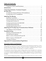
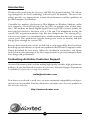
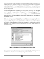
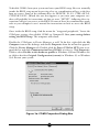
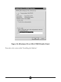
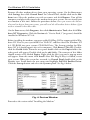
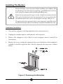
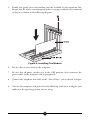
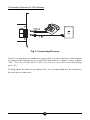
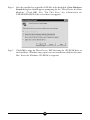
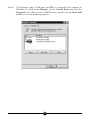
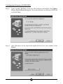
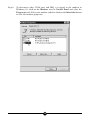
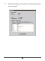
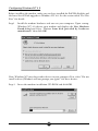
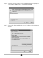
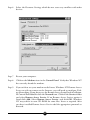
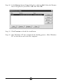
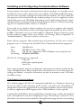
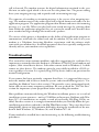
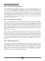
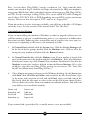
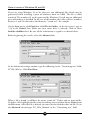
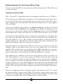
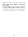
Table of Contents
Proprietary Notice and Disclaimer ..................................................... 1
Introduction ........................................................................................... 2
Contacting Actiontec Customer Support ............................................ 2
Do This First ........................................................................................... 3
For Windows 95 and Windows 98 Installations .................................. 3
For Windows NT 4.0 Installation ........................................................ 7
Installing The Modem ............................................................................ 8
Hardware Installation ......................................................................... 8
Connecting Devices To The Modem ................................................ 10
Configuring Windows 95 .................................................................. 11
Configuring Windows 95 OEM SR2 ................................................. 14
Configuring Windows 98 .................................................................. 18
Configuring Windows NT 4.0 ........................................................... 25
Installing and Configuring Communications Software .................... 29
The Modem’s Voice Features .......................................................... 29
Troubleshooting .................................................................................. 30
Windows 95 and Windows 98 .......................................................... 31
Uninstalling the Modem ................................................................... 33
Note to users of Windows 95 and 98 ............................................... 34
Note to users of Windows NT ......................................................... 35
Common Problems ......................................................................... 35
Appendix B: Communications Regulations ...................................... 38
Proprietary Notice and Disclaimer
Unless otherwise noted, this document and the information herein disclosed are proprietary to Actiontec Electronics, Inc. Any person or entity to whom this document is furnished or who otherwise has
possession thereof, by acceptance agrees that it will not be copied or reproduced in whole or in part,
nor used in any manner except to meet the purposes for which it was delivered.
The information in this document is subject to change without notice and should not be construed as
a commitment by Actiontec. Although Actiontec will make every effort to inform users of substantive
errors, Actiontec disclaims all liability for any loss or damage resulting from the use of this document or
any hardware or software described herein, including without limitation contingent, special or incidental liability.
Note: PC is a trademark of IBM Corporation. Windows 95 and Windows NT are trademarks of Microsoft, Inc. K56flex is a trademark
of Lucent Technologies, Inc. and Rockwell International.
1
Introduction
Thank you for purchasing the Actiontec 56K ISA Lite internal modem. The Advantage incorporates the latest technology in host-based V.90 modems. This new technology provides vast improvements in both the performance and the capabilities of
personal computer fax/modems.
Controller-less modems, also known as Win Modems or Windows Modems, utilize
your computer’s Central Processing Unit (or CPU) to perform some of their functions. The modems on-board Digital Signal Processing (DSP) circuitry handles the
most processor-intensive functions such as V.90 and V.34 modulation leaving the
system CPU to perform mundane tasks like data compression. This sharing of system resources results in a streamlined, more reliable modem that does not tax overall
system speed. This modem also benefits from greater access to memory and disk
storage space through the system CPU.
Because their control code resides on disk and is easily upgradable, host-based modems keep up with advances in speed and capabilities that Personal Computers make.
Simply download the new driver, follow the installation instructions, and reboot
your system to take advantage of the latest improvements in personal computer hardware design and performance.
Contacting Actiontec Customer Support
Actiontec Electronics prides itself on making high-quality, durable, high-performance
products. If you should need assistance, the Actiontec Technical Support Department
is available for registered users only via e-mail at:
[email protected]
New drivers are released as need arises to insure maximum compatibility and operation of your new modem. Find out about these and other new Actiontec products at
the Actiontec web site:
http://www.actiontec.com
2
Do This First
Please read the following tips before attempting to install your new modem.
For Windows 95 and Windows 98 Installations
Be sure to remove all other modem drivers from your operating system. To do this,
right-click My Computer, choose Properties from the menu that appears, then click
on the Device Manager tab. Double-click the Modems icon in the list of devices to
show the modems installed. Click once on the icon next to any modems in this list to
select them. When all of the modems are selected, click Remove.
Turn off the computer and physically remove your old modem from the system. Once
you remove the old modem and its drivers from your system, you will need the old modem
driver diskette if you wish to reinstall it at a later date.
Restart the computer. On the taskbar, click Start. On the Start menu, click Settings,
then click Control Panel. Double-click on the Modems icon. Select all of the listed
modems and click Remove. Shut down (rather than restart) the computer. Wait 5
seconds before turning it back on.
Figure 1: The Modems Properties Panel
3
If you are going to use the Telephone Answering Machine (TAM) functions of the
modem and you are running Windows 95, you need to install a software component
called Unimodem V. If you have Windows 95 OEM Service Release 2 (Version
4.00.950 B) or a later version of Windows, this component comes standard as part of
the operating system.
To find out which version of Windows 95 you are using, right click the My Computer icon on the desktop, and choose Properties from the menu that appears. If the
version of Windows 95 is 4.00.950 or 4.00.950A, go to the UNIMODEM directory
of the CD-ROM that came with your modem and right-click on the UNIMODV.INF
icon, (this may be named UNIMODV) then click on Install.. Restart your computer
to enable the drivers.
Make sure you have an available COM port and IRQ on your computer. The modem needs one IRQ and one COM Port in order to function. To check which interrupts are available on your system, double-click on the System icon in Control Panel
and click the Device Manager tab. Highlight Computer in the dialog box and click
Properties. There are only 16 (0 to 15) interrupts in a PC system. Make a note of any
interrupt not listed.
Figure 2: Windows 95 IRQ Resources Dialog Box
If you do not have any free interrupts you may need to disable a COM port for an
installed device that you are not currently using, such as COM2.
4
To disable COM2, boot your system and enter your BIOS setup. You can normally
invoke the BIOS setup menu by pressing a key or a combination of keys at the first
boot up screen. Some of the common keys are DELETE, F1, F2, CTRL+ALT+S,
CTRL+ALT+ESC. (Watch the text that appears as you turn your computer on-there will probably be instructions on how to enter “SETUP”--following these instructions will give you access to the BIOS. If none of these key combinations work,
refer to your computer’s user’s manual for instructions on how to access the BIOS
setup.
Once inside the BIOS setup, find the menu for “integrated peripherals,” locate the
COM port settings, then disable COM2 or Comport B. Save your settings before
exiting the BIOS Setup. The computer will reboot.
Disable the COM port in Device Manager as well. To do this, right-click the My
Computer icon on the desktop, and choose Properties from the menu that appears.
Click the Device Manager tab. Double-click the Ports (COM & LPT) icon to expand the list and click Communication Port (COM2) to select it. Click Properties.
Click to select Disable in this hardware profile in Windows 95B and Windows 98,
or click to deselect Original Configuration (current) in Windows 95 or Windows
95A. Restart your system.
Figure 3a: COM2 Properties Dialog Box
5
Figure 3b: Windows 95 (or 95A) COM2 Disable Panel
Proceed to the section titled “Installing the Modem.”
6
For Windows NT 4.0 Installation
Remove all other modem drivers from your operating system. On the Start menu,
click Settings then click Control Panel. In Control Panel, double-click on the Modems icon. Select the modem you wish to remove and click Remove. Turn off the
computer and physically remove the modem from your system. Do not install your
new modem at this time. Follow the procedures below. Once you remove the old modem and its drivers from your system, you will need the old modem driver diskette if you
wish to reinstall it at a later date.
On the Start menu, click Programs, then click Administrative Tools, then click Windows NT Diagnostics. Click the Version tab. “Service Pack 3” (or greater) should be
installed in Windows NT 4.0.
Before installing the modem, you must enable ISA Plug-N-Play support within Windows NT. First set your system BIOS to “PnP OS” and then insert the Windows NT
4.0 CD-ROM into your systems CD-ROM Drive. The Startup window for Windows NT 4.0 should appear after a few moments. Click Browse This CD. Doubleclick the Drvlib folder. From the new panel double-click on the Pnpisa folder. Another panel will appear. Double-click on the x86 folder. The contents of this folder
should contain a file labeled Pnpisa. Right-click the file’s icon and a pop-up menu
will appear. From this menu click Install. After ISA Plug-N-Play is enabled, restart
your system. When the system has restarted, in Control Panel double-click on the
Devices icon. Scroll down the new menu and highlight PnP ISA Enabler Driver.
Click the Startup button and select the System option. See Fig.4 below.
Fig. 4: Devices Window
Proceed to the section titled “Installing the Modem.”
7
Installing The Modem
Always discharge static electricity before handling your modem. You
may discharge static electricity by touching a grounded metal structure
or by using any commercially available grounding strap.
Make sure the expansion slot type is 16-bit, which has two slots to fit the
ISA card. 8-bit slots have only one connector. If you use an 8-bit slot,
the modem will not have access to the higher interrupts (IRQ 9-12).
The position of the expansion slots in your computer may differ from
the illustration shown but the installation procedure should be the same.
Hardware Installation
1.
Turn off the computer and all peripheral devices connected to it.
2.
Unplug the computer power cord from the wall receptacle.
3.
Remove the computer’s cover. Refer to your computer owner’s manual for
instructions.
4.
Remove the screw securing the expansion slot cover behind one of the computer’s
available 16-bit ISA expansion slots. Lift the expansion slot cover out as shown
below.
Figure 5: Removing the Backplate
8
5.
Firmly, but gently, insert the modem into the available 16-bit expansion slot.
Ensure that the card is seated properly before securing it with the screw removed
in Step 4, as shown in the following diagram:
Figure 6: Installing The Modem
6.
Put the chassis cover back on the computer.
7.
Be sure that all power switches are in the OFF position, then reconnect the
power cables to the computer and its peripherals.
8.
Connect the telephone line cable to the “Line (Telco)” jack as shown in Figure
7.
9.
Turn on the computer and proceed to the following sections to configure your
modem to the operating system you are using.
9
Connecting Devices To The Modem
Fig.7: Connecting Devices
On the rear panel of your modem are input jacks to connect devices to the modem.
As shown in the diagram, there are jacks for connection to a “phone” and to a phone
“line.” The connector labeled Line (Telco) is meant to be connected to a standard analog
phone line.
To help reduce the load on your phone line, it is recommended that the modem be
the only device connected.
10
Configuring Windows 95
Step 1
Upon startup, Windows 95 detects the modem and displays the New
Hardware Found dialog box. Select “Driver from disk provided by hardware
manufacturer” then click OK.
Step 2
Type your CD-ROM drive’s drive letter into the Copy manufacturer’s files
from box. Insert the Installation CD-ROM and click OK.
Step 3
If Windows asks for an installation disc, click OK and type the drive letter
for you CD-ROM drive in the dialog box that appears and click OK.
11
Step 4
After the installer has copied the .INF files to the hard disk, a New Hardware
Found dialog box should appear prompting for the “Wave Device for Voice
Modem”. Click OK. (See “Do This First” for information on
UNIMODEM.INF if this screen does not appear).
Step 5
Click OK to copy the Wave Device .INF file from the CD-ROM drive to
the hard drive. Windows may request its own installation diskettes for some
files. Insert the Windows CD-ROM as required.
12
Step 6
To determine what COM port and IRQ is assigned to the modem in
Windows 95, click on the Modems icon in Control Panel and select the
Diagnostic tab. Click on the COM Port icon and then on the More Info
button to view the modem properties.
13
Configuring Windows 95 OEM SR2
Step 1
Upon startup, Windows 95 detects the modem and launches the Update
Device Driver Wizard dialog box. Insert the modem’s installation CD-ROM
and click Next.
Step 2
After Windows 95 has found the updated drivers for your modem, click
Finish.
14
Step 3
If Windows asks for its own installation disc, click OK. Insert the requested
CD-ROM, type the drive letter of your CD-ROM in the dialog box that
appears next, and click OK.
Step 4
After the Wizard has copied the .INF files to the hard disk, it should detect
“Wave Device for Voice Modem” and prompt for its driver. Click Next.
.
Step 5
Click Finish to copy the Wave Device .INF file from the CD-ROM drive to
the hard drive. Windows may request its own installation diskettes for some
files. Insert the Windows CD-ROM as required.
15
Step 6
To determine what COM port and IRQ is assigned to the modem in
Windows 95, click on the Modems icon in Control Panel and select the
Diagnostics tab. Select your modem and then click on the More Info button
to view the modem properties.
16
Step 7
Remember this COM port number. When you install your Data/Fax software
or internet browser program, you may need to set your modem port location
to this same number.
17
Configuring Windows 98
Step 1
After installing the modem hardware, turn on your computer. Windows
will detect the modem and start the Add New Hardware Wizard. Click
Next.
Step 2
The Add New Hardware Wizard will ask if you would like it to “search for
the best driver for your device (Recommended).” If this option is not already
selected, click it, then click Next.
18
Step 3
The Wizard will ask where it should search for the drivers. Click “CDROM drive” to select it. Make sure the installation CD-ROM is in the CDROM drive. Click Next.
Step 4
Next the Wizard will identify the driver file and report its location on the
CD-ROM drive. Click the Next button to copy and install the driver.
19
Step 5
After copying the files to your hard drive, the wizard will report that it is
finished installing the drivers for the modem. Click Finish.
Step 6
Windows will now detect a “Wave Device for Voice Modem” and start the
Add New Hardware Wizard again to find the drivers for the voice capabilities
of your modem. Click Next.
20
Step 7
The Add New Hardware Wizard will ask if you would like it to “search for
the best driver for your device (Recommended).” If this option is not already
selected, click it, then click Next.
Step 8
The Wizard will ask where it should search for the drivers. Click “CDROM drive” to select it. Make sure the installation CD-ROM is in the CDROM drive. Click Next.
21
Step 9
Next the Wizard will identify the driver file and report its location on the
CD-ROM drive. Click the Next button to copy and instal the driver.
Step 10 Windows will copy and install the files, and then display the dialog box
below, reporting that the process has finished. Click Finish.
22
Step 11 Windows will finish loading. To make sure your modem has been installed
correctly, click Start on the taskbar. On the Start menu, click Settings, then
click Control Panel. In Control Panel, double-click the Modems icon, then
click the Properties tab to bring it to the front. On the Modems Properties
tab, click the COM port number (COM 3 in the illustration below) to
select the modem, then click More Info.
23
Step 12 Check that the More Info dialog box that appears on your screen matches
the illustration below. Make a note of the interrupt (also known as an IRQ)
and the port number. These will be needed to configure your
communications software.
Your modem is now installed and configured for use with Windows 98.
24
Configuring Windows NT 4.0
Before installing the modem, make sure you have installed the PnP ISA Enabler and
the latest Service Pack upgrade to Windows NT 4.0. See the section titled “Do This
First” for details.
Step1
Install the modem hardware and turn on your computer. Upon startup,
Windows NT 4.0 detects your modem and displays the New Hardware
Found dialog box.Select “Driver from disk provided by hardware
manufacturer” then click OK.
Note: Windows NT may detect other devices in your computer. If so, select “Do not
install a driver (Windows will not prompt you again)” for these devices.
Step 2
Insert the modems installation CD-ROM and click OK.
25
Step 4
A panel for selecting the device to be installed should appear. Highlight the
“V.90 Windows Modem (LHT)” selection and click OK.
Step 5
If you see the following dialog box, you will need to set the configuration
manually.
26
Step 6
Select the Resource Settings which do not cause any conflicts with other
devices.
Step 7
Restart your computer.
Step 8
Click on the Modems icon in the Control Panel. Verify that Windows NT
has correctly found the modem.
Step 9
If you wish to use your modem to dial into a Windows NT Remote Access
Server or wish to connect to the Internet, you will need to configure Dialup Networking. If you do not see the Remote Access Setup Panel installation,
In Control Panel double-click the Network icon. Click on the Services folder
and select Remote Access Service. If no Remote Access Service option is
listed click Add. Select Remote Access Service. and click OK. Windows
NT may ask for its own CD-ROM for some files. Insert as required. After
you have installed Remote Access Service add the appropriate protocols as
directed.
27
Step 10 At the Remote Access Setup dialog box, click on Add. Select the Remote
Access Setup device you wish to add and Click OK.
Step 11 Click Continue to finish the installation.
Step 12 After Windows NT has completed the binding process, allow Windows
NT to shut down and restart the computer.
28
Installing and Configuring Communications Software
If your modem came with a communications software package, it is strongly recommended that you use this software for your modem. It’s default installation parameters have been specially configured to work with this modem. The Users Guide for
this program can be found inside the modem package. It can be supplied in either
soft-bound copy or on CD-ROM (depending on the model you purchased). Some
configurations are packaged without communications software. Check your packaging to see if communications software is included.
If you wish to use another software package, be sure that it supports this modem.
Most Software Manufacturers have a listing of supported modems on their websites
or BBSs. Check these sites to see if this model is supported. If you are unsure or your
brand of software supports only a few modems, try selecting “Hayes Compatible” or
“Standard Modem.” This may work in certain cases.
Some software programs allow manual input of parameters. For the users of these
programs, here is a listing of the Data/Fax/Voice Command Standards supported.
Data:
Fax:
Voice:
Init String:
TIA/EIA-602
TIA/EIA-578 for Class 1 Fax
TIA IS-101 support for TAD (Telephone Answering Device)
AT&F&C1&D2W2
TIA IS-101 Commands not supported:
Caller ID
Full Duplex Speakerphone
VoiceView
Note: some programs must be configured to communicate with the modem on the
same COM port and or IRQ setting used by the modem. See the section titled “Installing the Modem” section for instructions on how to determine your COM Port
and IRQ settings.
The Modem’s Voice Features
This modem supports TIA IS-101 commands applicable to a Telephone Answering
Device. In order to take advantage of this feature, you will need a Sound Blaster®
compatible sound card equipped with an external microphone and external speakers.
A software application which supports these TAM functions is also required.
A modem based Telephone Answering Machine works by using a sound card equipped
with a microphone to record an outgoing message. This message is stored as a .wav
file which is transferred to the modem by the application program when an incoming
29
call is detected. The modem converts the digital information contained in the .wav
file into an audio signal which is then sent over the phone line. The person calling
hears your outgoing message and responds with an incoming message.
The sequence of recording an incoming message is the reverse of an outgoing message. The modem converts the audio signal into a digital format and sends it to the
application program. The application program then formats and stores the incoming
message as a .wav file. When you play back your stored messages by selecting them
from within the application program, they are sent to the sound card. You then hear
your recorded messages through the sound card’s speakers.
The success of this process is dependent on the ability of the application program to
communicate with both the sound card and the modem. If you wish to use your
modem as a Telephone Answering Machine, experiment with the software witch
came with your modem first. Its default parameters have been specially configured to
identify and use your modems voice capabilities.
Troubleshooting
This section lists some common problems and offers suggestions for a solution. It is
important to remember that this modem is a Windows 95/98/NT based modem and
requires 32bit virtual device drivers. It therefore cannot work in Windows 3.1 which
cannot use these drivers. The modem cannot be successfully installed in a DOS system, regardless of version. It is a purely Plug-N-Play device and has no provisions for
manual configuration.
If you cannot find your particular symptom listed here, it is suggested that you remove the modem and its drivers from the system and reinstall them again (see “Uninstalling the Modem” later in this section). This provides a new, uncorrupted installation and can cure many temporary problems. Be sure to check the “Do This First”
section for important system preparation before reinstalling the modem.
Most problems encountered during the Windows installation process are a result of
insufficient system resources—no free COM Ports or Interrupts. Problems with Windows NT 4.0 installations are usually a result of not having ISA Plug-N-Play enabled. For these reasons it is strongly recommended that you carefully follow the preinstallation procedures outlined in the Do This First section. These steps have been
thoughtfully chosen to help minimize difficulties during the installation of the modem in both Windows 95, Windows 98, and Windows NT 4.0.
If your modem has installed but is not functioning, try the following troubleshooting
procedures.
30
Windows 95 and Windows 98
Step 1: Check System Resources.
In Control Panel double-click the System icon. Click the Device Manager tab. In
the list of devices, double-click the Modems icon to show what modems are installed. If there is no Modems icon, your modem did not install. If your modem is
listed, check that there is no yellow exclamation mark or red “X” over the modem’s
icon (If there is some alteration to this icon, go to Step 2.) If any other modems are
listed, highlight the modem by clicking once on the icon next to the listed modem
and then click Remove. Turn off your computer. Wait 5 seconds and turn your computer back on. Repeat Step 1.
Step 2: Check Modem Properties.
From the Device Manager tab within System Properties, double-click the Modems
icon in the list of devices to show what modems are installed. Highlight your modem
by clicking once on the icon and then click the Properties button. Read the “Device
Status” under the General tab to see if the device is working properly. Check the
Device Usage box and make sure “Disable in this hardware profile” is not selected.
(Windows 95 OEM SR2 and Windows 98 only). Make a note of the COM port and
IRQ the modem is using.
Errors reported in the Device Status box generally refer to conflicts. Click the Resources tab and read the “Conflicting Device List.” If a conflict is present, click to
deselect “Use automatic Setting” and select a configuration that does not cause conflicts. Manually change the address and IRQ settings if needed. (Refer to Windows
95 on-line help for detailed about how to change these settings.) Click OK. If there
is no setting free of conflicts, turn to the section of this manual titled “Does Not
Install.”
Step 3: Modem Diagnostics.
In Control Panel double-click the Modems icon. Your modem should be listed. If
any other modem is also listed, click to select each of these other modems and then
click the Remove button. Turn off your computer, wait 5 seconds and turn the power
back on. Return to Control Panel and double click the Modems icon. Click the
Diagnostics tab. Click the COM port designation next to your modem. Click More
Info. You should see a dialog box like the following.
31
Figure 8: More Info Panel
If you receive an error message or the panel is blank, go to the section of this manual
“Does Not Install.”
Step 4: Does Not Install
The most likely reason for a non-installation in Windows 95 or 98 is a lack of IRQ
resources. The modem needs one IRQ and one COM Port in order to function.
Computers are usually equipped with a sound card, CD-ROM drive, Hard-drive,
floppy drive, video card, two COM ports, one LPT port, keyboard, and a mouse.
Each of these devices require at least one IRQ (interrupt) in order to function.
This section deals with the process of freeing IRQs and configuring P-N-P (Plug-NPlay) This requires that you know how to enter your computer system’s BIOS Setup
Routine—read your computer user’s manual for information on how to enter into
and use the BIOS setup.
Once inside the BIOS Setup, find the Plug-N-Play configuration and check the selection for “Operating System.” This can be found within the “Advanced”, “PNP/
PCI Configuration”, or “Plug and Play Configuration” section depending on the
BIOS Manufacturer. If you have an Operating System selection, set it to “Plug-N-
32
Play”, or if you have “Plug N Play” settings, set them to “on.” Next, from the information you noted in Step 2, find the interrupt selection for the IRQ your modem is
using (some BIOS don’t allow individual selection of interrupts to ISA, Plug-N-Play,
or PCI). Set this interrupt to Plug-N-Play. This can be called ICU (ISA Configuration Utility), ICU/PCI, ISA, or PNP depending on your BIOS version and manufacturer. Do not set this interrupt to “PCI” only or to “Legacy ISA”.
If you do not have any free interrupts available, you will have to disable a COM port
currently in use. See the section of this manual titled “Do This First”.
Uninstalling the Modem
If you are uninstalling the modem in Windows in order to upgrade software or reinstall the modem as part of a troubleshooting process, it is important to follow these
directions carefully. Following these instructions out of sequence can cause your system to cease responding to the mouse, the keyboard, or both.
1.
In Control Panel, double-click the System icon. Click the Device Manager tab.
In the list of device groups, double-click the Modems icon. Click to select the
listing for your modem and then click the Remove button.
2.
In Control Panel double-click the Modems icon. If your modem is listed, click
once on the icon next to the modem and then click Remove.. If the New Hardware
Found panel comes up, click Cancel. (Your modem should not be listed in the
Modems section after you have deleted it from the Device Manager. If it is, this
could be a sign that your Plug-N-Play settings are not correct. See “Does Not
Install” for information about Plug-N-Play.)
3.
Close all open programs and return to the Windows desktop. On the Start menu,
click Find, then click Files or Folders and search for the files listed below. Type
in the name and extension of each and click Find. Once you find each of the
files listed, click the file name to select it then on the File menu choose Delete.
(Do not delete these files from your modem installation diskette. You will need
your diskette to reinstall the modem).
ltcom.vxd
ltmodem.vxd
ltvcd.vxd
ltmodem.sys
ltwave.inf
ltdft.inf
ltdsvd.dll
ltports.inf
If you cannot find a particular file, it usually means it was not installed.
33
Note to users of Windows 95 and 98
If you are using Windows 95 or 98, there are two additional files which may be
generateed when installing a piece of hardware from an OEM. The file is called
oem#.inf. The number (#) used is generated by Windows 95 each time an additional
piece of hardware is installed. In the case of the modem, these files wil have numbers
between 1 and 99 reflected in the filename--”oem8.inf ”, for example
On the Start menu, click Find then click Files or Folders. At the first screen, type in
*.inf in the Named: box. Make sure your entire drive is selected. Click to select
Include subfolders box. Be sure all the information is typed in as shown below.
Before beginning the search, select the Advanced tab.
At the Advanced settings window, type the following in the “Containing text” field:
LT Win Modem. Click Find Now.
When a file is found, it will have the name “oem#.inf.” Delete only an oem inf file.
To delete a file, highlight the file name by clicking once and then choose Delete from
the File menu. After the file is deleted, you now need to find the other inf file. Go to
the Advanced tab and type “LT_Win_Modem” in the “Containing text” field:
34
After Windows finds the other file, delete it as before. Restart your system and follow
the installation procedures in the section of this manual titled “Installing the Modem.”
Note to users of Windows NT
Windows NT 4.0 installation problems are often due to inadequate preparation.
The following conditions must be meet before attempting to install the modem or it
will not be seen or correctly installed by the system. (See the “Do This First” at the
beginning of this manual).
•
•
•
•
ISA Plug-N-Play support must be installed within Windows NT.
Plug-N-Play OS must be enabled in your system BIOS.
You must have the latest Service Pack upgrade installed.
There must be a free IRQ and COM Port available for the modem.
If you need help on freeing an interrupt, see “Windows 95 Does Not Install” for a
discussion of this topic. The “Special Situations” and “Plug-N-Play BIOS” sections
also apply to Windows NT 4.0. Do not use the procedure in Windows 95 for uninstalling the modem.
Common Problems
No Dialtone Error
Make sure you have connected the phone cable into the right connector on the back
of the modem. See “Figure 7: Connecting Devices.”
You may have too many devices connected to the phone line. Remove all other equipment.
Your modem may not recognize overseas dialtone. Use the AT command string “ATX0”
to have the modem ignore the dialtone before dialing.
Communications Software Does Not Work
The communications software must be configured to the same COM Port and IRQ
as the modem.
Does the communications software support this modem? See “Installing and Configuring Communications Software.”
If you are using different communications software from that supplied with the modem, try installing the supplied software first to verify its functionality.
35
Nothing Appears On The Screen When I Type
Issue the command ATE1 to the modem to enable command echo. This will let you
see what you type.
Cannot Connect at 56K
Note: Current FCC regulations limit your maximum connection rate to 53Kbits/s.
The number you are calling may not support V.90 or K56flex protocols. Some Internet Service Providers have special numbers that you must call to make 56K connections. Contact your service provider and ask if the number you are using supports
V.90 or K56flex.
Check the maximum speed setting in the Modem Properties window. In Control
Panel, double-click the Modems icon. Highlight your modem by clicking once on
the icon next to the modem and then click the Properties button. Select the General
tab and look at the setting in the Maximum speed box. Make sure this is set to 115200.
You may have other telephone devices connected to the phone line. To achieve the
best connection possible, remove all extra devices connected to the telephone line
when the modem is in use. This includes extension phones, answering machines,
cordless phone bases, caller ID boxes and their cables. This reduces the load on your
phone line and keeps signal attenuation to a minimum.
Keep the length of your phone line cable to 10 feet or less. If necessary, move the
computer closer to the phone socket. Don’t lay your cabling close to an electrical
appliance like a refrigerator or air conditioner unit. High current devices can transmit 60 cycle “hum” to your modem through the phone cord. This may cause frequent renegotiations or line disconnects while the appliance is running.
The telephone line conditions at the time of your call may not let you connect at
56K. The modem has a connection sequence of K56flex, then V.90, then V.34, and
so on. The modem attempts to make the highest connect rate that your telephone
line can support at the time of negotiation. If the line conditions (noise, telephone
company routing, etc.) won’t allow a high data rate connection, then the modem will
automatically connect at the most reliable rate. Try making the call again after a few
minutes. The routing of the call may improve your chances of making a 56K connection.
If you are attempting to make a call from an office and you have to dial “9” to reach
an outside number, you are using a PBX. The modem cannot connect faster then
V.34 if you are using a PBX. Try using the line that is connected to a fax machine. Fax
machines are usually connected to a dedicated line and not a PBX.
36
Your phone line may not support or may only intermittently support a 56K connection. There are many conditions that must be met before a 56K connection can be
established. The telephone company must have you connected to the (Public Switched
Telephone Network) in a particular way. The modem you are calling must also support the same protocol.
The drivers for your modem are constantly being refined to address problems with
compatibility, interoperability, and performance. Conditions that were thought insurmountable only months ago are now things of the past. As the industry converts
to the new V.90 standard, current problems of connectivity and interoperability could
also be things of the past. Check for driver upgrades on a regular basis. A problem
connecting to a particular provider might be fixed by a simple software upgrade.
37
Appendix B: Communications Regulations
FCC Regulations
The following statements are provided in accordance with the Federal Communications Commission (FCC) regulations. Please read these statements carefully before
installing your modem.
FCC Part 68 Requirements
This equipment complies with Part 68 of the FCC Rules. On the bottom of this
equipment is a label that contains, among other information, the FCC Registration
Number and Ringer Equivalence Number (REN) for this equipment. If requested,
this information must be given to the telephone company.
The REN is used to determine the maximum number of devices connected to your
telephone line that will ring in response to an incoming call. In most, but not all,
areas, the total REN of devices connected to a line should not exceed five (5.0). To
find out the total permitted in your area, contact your local telephone company.
If your telephone equipment causes harm to the telephone network, the telephone
company can discontinue your service temporarily. If possible, the company will
notify you in advance. But if advance notice isn’t practical, you will be notified as
soon as possible. You will be informed of your right to file a complaint with the FCC.
Your telephone company can make changes in its facilities, equipment, operations,
or procedures that could affect the operation of your equipment. If so, you will be
notified in advance so you can make the changes needed to maintain uninterrupted
service.
If you experience trouble with this equipment, please contact the manufacturer at the
address given in this manual. The telephone company may ask that you disconnect
this equipment from the network until the problem has been corrected or until you
are sure that the equipment in is not malfunctioning.
This equipment may not be used on public coin service provided by the telephone
company. Connection to party lines is subject to state tariffs.
38
Declaration of Conformity
This equipment has been tested and found to comply with the limits for a Class B
digital device, pursuant to Part 15 of the FCC Rules. These limits are designed to
provide reasonable protection against harmful interference in a residential installation. This equipment generates, uses and can radiate radio frequency energy and, if
not installed and used in accordance with the instructions, may cause harmful interference to radio communications. However, there is no guarantee that interference
will not occur in a particular installation. If this equipment does cause harmful interference to radio and television reception, the user is encouraged to try to correct the
interference by one or more of the following measures:
• Reorient the receiving antenna.
• Increase the separation between the equipment and receiver.
• Connect the equipment into an outlet on a circuit different from that
to which the receiver is connected.
• Consult the dealer or an experienced radio/TV technician for help.
CAUTION: CHANGES OR MODIFICATIONS NOT EXPRESSLY
APPROVED BY THE PARTY RESPONSIBLE FOR COMPLIANCE
COULD VOID THE USER’S AUTHORITY TO OPERATE THE
EQUIPMENT.
39
Canadian Department Of Communications (CDOC)
Requirements for End Users:
Notice: The Canadian Department of Communications label identifies certified equipment. This certification means the equipment meets certain telecommunications
network requirements. The Department does not guarantee the equipment will operate to the user’s satisfaction.
Before installing this equipment users should ensure that connection to the line is
allowed by the local telecommunications company. The equipment must also be installed using an acceptable method of connection. In some cases, the company’s inside wiring associated with a single line individual service may be extended by means
of a telephone extension cord. Compliance with the above conditions may not prevent degradation of service in certain situations.
Repairs to certified equipment should be made by an authorized Canadian maintenance facility designated by the supplier. Any repairs or alterations made by the user
to this equipment, or equipment malfunctions, may give the telecommunications
company cause to request the user to disconnect the equipment.
Users should ensure for their own protection that the electrical ground connections
of the power utility, telephone lines, and internal metallic water pipe system, if present,
are connected together. This precaution may be particularly important in rural areas.
Caution: Users should not attempt to make such connections themselves, but should
contact the appropriate electric inspection authority, or electrician, as appropriate.
40