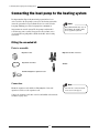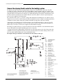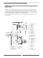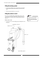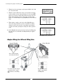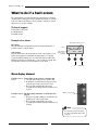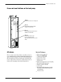
1
WORCESTER GREENSTORE
6kW, 7kW, 9kW & 11kW Combi
HEAT PUMP
GB/IE
INSTRUCTION MANUAL
INSTALLATION, COMMISSIONING
& SERVICING
Table of contents
BUILDING REGULATIONS ..................................................................................................................................3
For the Installer ................................................................................................ 5
Important information to the installer ................................................................. 6
Technical support ...................................................................................................................................................6
Checklist .......................................................................................................... 6
What the deliver y includes ................................................................................ 7
Dimensions and plumbing connections ............................................................... 8
The heat pump and collector hose in general....................................................... 9
Transporting the heat pump ....................................................................................................................................9
Positioning the heat pump .......................................................................................................................................9
Maximum working temperatures ............................................................................................................................9
Minimum working temperatures .............................................................................................................................9
Fit the filters ............................................................................................................................................................9
Collector hose ........................................................................................................................................................10
Installing the expansion vessel ...............................................................................................................................12
Compact collector ..................................................................................................................................................13
Connecting the heat pump to the heating system ............................................... 14
Fitting the unvented kit .........................................................................................................................................14
Use in hard water areas ........................................................................................................................................17
Connecting to the heating system without a bypass: ................................................................................................17
Connect heat pump Combi model to the heating system .........................................................................................18
Individual temperature control in each room and increasing volume of internal water .........................................19
Filling the heating system ......................................................................................................................................20
Filling the collector circuit ....................................................................................................................................20
Connecting the heat pump to the power supply ................................................. 23
Installation of sensors ............................................................................................................................................23
External connections to the heat pump ..................................................................................................................24
Connecting the general alarm, external input and softstart ...................................................................................25
Installer and ser vice menu (I/S) ...................................................................... 26
How to use the control panel .................................................................................................................................26
Commissioning the heat pump ......................................................................... 27
Manual test run of the heat pump .........................................................................................................................27
Start the heat pump ..............................................................................................................................................27
Menu displays which may need adjustment or checking .........................................................................................28
Drying program for floor screed .............................................................................................................................31
Start the heat pump with only additional heat.......................................................................................................32
Important points to check after start up.................................................................................................................32
Maintenance ................................................................................................... 33
Unscrew the front cover ........................................................................................................................................33
Sight glass .............................................................................................................................................................33
Filters ...................................................................................................................................................................34
Protective anode ...................................................................................................................................................34
Expansion vessel....................................................................................................................................................35
What to do if a fault occurs .............................................................................. 36
Menu display dimmed ...........................................................................................................................................36
Fuses and reset buttons on the heat pump .............................................................................................................37
All alarms ............................................................................................................................................................37
Technical information ...................................................................................... 46
2
BUILDING REGULATIONS
This appliance must be installed and serviced only by a competent person in accordance with the current: IEE Regulations,
Building Regulation, Building Standards (Scotland) (Consolidation), Building Regulations (Northern Ireland), local water
by-laws, Health & Safety Document 63S (The Electricity at Work Regulations 1989), IS 813 (Eire) and other local requirements.
The relevant Standards should be followed, including:
BS7074:1 : Code of practice for domestic and hot water supply
EN:12828 : Central heating for domestic premises
BS7593 : Treatment of water in domestic hot water central heating systems
BS EN 14511
BS EN 814
BS EN 378
The Health and Safety at Work Act 1974
The Management of Health and Safety at Work Regulations 1999
The Construction (Health, Safety and Welfare) Regulations 1996
The Construction (Design and Management) Regulations 1994
The Lifting Operations and Lifting Equipment Regulations 1998
Where no specific instruction is given, reference should be made to the relevant codes of Practice.
Potable water:
All seals, joints, compounds (including flux and solder) and components used as part of the secondary domestic water
system must be approved for use with potable water supplies.
This is to certify that the above ranges of products manufactured by BBT Thermotechnology have been tested and found
to comply with –
1.
2.
the requirements of the (Water Fittings) Regulations 1999 for England and Wales, the Water Byelaws 2000, Scotland
and the Water Regulations Northern Ireland.
the requirements of the UK Building Regulations:
The Building Regulations 1991 (England & Wales) Requirements G3, L1 and Regulation 7. The Building Standards
(Scotland) Regulations 1990. Regulation 10 (B2), 22 (J3.3a and J3.4), 27 and 28 (P2.6 and P3). The Building Regulations
(Northern Ireland) 2000.
Installation manual for the Worcester Greenstore Combi heat pumps
Worcester, 05.02.07
Part number: 8-716-113-342
Issue: b
Copyright © 2007.
3
600mm
PRODUCT CONTENTS LIST
600mm
Greenstore Combi Heat Pump.
Components included in deliver y:
Rubber feet
Outdoor sensor T2 (GT2) with cable
Room sensor T5(GT5)
Return sensor T1 (GT1)
4 bar Pressure Relief Valve
Valve with filter
Circlip pliers
Drain plug
Ball valve
Expansion vessel
Filling link with insulation and filter
Literature pack:
User manual
Installation manual
Guarantee card
1800mm
Unvented cylinder kit:
DHW expansion vessel
Expansion Vessel Hose
Wall mounting kit for expansion vessel
High flow rate inlet control set
Acetal tundish
4
For the Installer
Installation of the heat pump should be performed by a qualified installer.
This chapter includes a section recommending how the heat pump installer
should install, commission and service the heat pump. The installation
manual consists of a plumbing section and an electrical section. These provide
technical data such as measurements, wiring diagrams and installer menus.
Contents:
Important information to the installer
Checklist
What the delivery includes
Dimensions and plumbing connections
The heat pump and collector hose in general
Connecting the heat pump to the heating system
Connecting the heat pump to the power supply
External connections to the heat pump
Commissioning the heat pump
Maintenance
Technical information
Note
It is important that the installer also reads through the User manual. It contains
the information necessary to get a comprehensive understanding of the heat
pump.
5
Important information to the installer / Checklist
Important information to the installer
This manual provides all the information necessary to install the heat pump.
The manual is divided into several sections. The order of these is based on the
recommended installation sequence. Use the supplied checklist during installation.
Before installation remember:
Warning
The main power supply must be
disconnected before working on the
heat pump.
Installation of the heat pump should be performed by a qualified installer.
If the heat pump needs to be tilted during transit it may be temporarily tilted with the compressor downwards.
However, never lay the heat pump down or transport it horizontally.
Before the heat pump is commissioned, the heat transfer systems, the hot water cylinder and the heat pump must be
filled and vented.
Check that pipe connections on the collector and primary circuits are intact and have not shaken loose during
transport.
Heat pump installation and collector installation must be carried out in accordance with applicable regulations.
Technical support
For technical support please contact:
Technical Pre & Post sales
Tel: 08705-266241
Fax: 01905-752741
Checklist
Each heat pump installation is unique. However, the following checklist gives a general description of how the installation
should be carried out.
1.
2.
Stand the heat pump on a flat surface. Adjust the height using the rubber feet.
Ensure that the bore hole (if used) for the collector hose is bored according to applicable regulations (responsibility of
the drilling company). Check that the horizontal collector (if fitted) has been installed correctly.
3. Fit the incoming and outgoing pipes for the heating and heat transfer fluid circuits as well as the expansion tank.
4. Fit the particle filters and valves.
5. Connect any additional circulation pump, if required, to the heating system. Follow the instructions for the pump in
question.
6. Install the outdoor sensor and a room sensor if used.
7. Fill and vent the primary and collector systems before commissioning.
8. Connect the heat pump to the electrical system via an external isolation switch. Use the appropriate wiring diagram.
9. Connect a general alarm and external control if used.
10. Commission the heat pump by making all the necessary settings on the control panel.
11. Check the heat pump after commissioning. Top up the collector system if required.
6
What the shipment includes
What the delivery includes
The following components are included in the delivery of the heat pump:
Rubber feet
Quantity: 4
Filling link with insulation and filter
Quantity: 1
Return sensor T1 (GT1)
Quantity: 1
Cable: 4 m
Valve with filter
Quantity: 1
Outdoor sensor T2 (GT2) with cable
Quantity: 1
Literature pack
User manual
Installation manual
Guarantee card
Room sensor T5 (GT5) with cable:
Quantity: 1
Expansion vessel
Quantity: 1
Circlip pliers
Quantity: 1
Drain plug
Quantity: 1
4 bar pressure relief valve
Quantity: 1
Ball valve
Quantity: 1
DHW expansion vessel
Quantity: 1
High flow rate inlet control set
Quantity: 1
Expansion vessel hose
Quantity: 1
Acetal tundish
Quantity: 1
Wall mounting kit for expansion vessel
Quantity: 1
7
Dimensions and connections
Dimensions and plumbing connections
Required installation space
≥ 100
≥ 300
The following illustrations show the dimensions of the heat pump and plumbing connections. All measurements are stated
in millimetres.
In front of the heat pump a free area of 800 mm is
required for installation and servicing.
1800
Allow a side clearance of at least 100 mm on the sides
and behind the heat pump.
596
79
198
298
471
538
568,5
517
506
5
1
6
470
4
Electrical
connections
Elanslutningar
280,5
69
3
2
398
494
554
8
1
CH return
2
CH flow
3
Mains cold water in
4
Domestic hot water out
5
Heat transfer fluid (HTF) in
6
Heat transfer fluid (HTF) out
≥ 100
The heat pump and collector hose in general
The heat pump and collector hose in general
Transporting the heat pump
The heat pump should always be transported and stored in an upright position, never horizontally. Otherwise the suspension fittings inside the compressor can be damaged. If the heat pump must be tilted during entry to the installation site,
this should be done for as short a time as possible. The outer cover panels should be removed to avoid damage, if the heat
pump is moved without using the supplied pallet.
The heat pump must not be stored at temperatures below -10ºC.
Positioning the heat pump
It is important that the heat pump stands on a flat surface as it contains sensitive parts. The floor must be stable and have a
strength to carry at least 500 kg. Adjust the rubber feet so the heat pump does not lean.
The temperature surrounding the heat pump should be between 0ºC and 35ºC.
The installer should take sound insulation into consideration when positioning the heat pump.
Maximum working temperatures
The heat pump can work at a maximum return water temperature of approximately 57ºC. If the temperature rises above
this value the heat pump will stop for safety reasons.
The electric heater will stop if the temperature rises above 55ºC. The maximum outgoing temperature to the heating
system is around 65°C.
Minimum working temperatures
The heat pump supplied is preset to a minimum temperature of collector fluid -10°C inlet and -10°C outlet. The heat pump
can operate at inlet temperatures down to -5°C, lower inlet temperatures are not recommended.
The preset values can be changed during commissioning.
Fit the filters
The task of the filters is to filter out dirt before it can enter the heat pump.
Fit the filter for the collector circuit on the incoming pipe from the collector.
Fit the filter for the primary circuit on the incoming pipe from the heating system.
Both filters should be fitted as close to the heat pump as possible and placed horizontally. Make sure that the direction of
flow is correct.
9
The heat pump and collector hose in general
Collector hose
The task of the collector hose is to convey the heat transfer fluid through the
ground to gain a few degrees of heat. The hose is a thin-walled plastic hose of
type PEM 40 x 2.4 PN 6.3. SDR11.
Installation and backfilling around the collector hose
Installation of the collector and backfilling the soil around the collector hose
should follow applicable material and working descriptions and regulations.
It is important that the filling material does not contain stones or other sharp
objects that can damage the collector hose.
Use hose pliers, not a saw, when cutting the collector hose. Deburr the end of
the pipe internally and externally. It is important that no dirt or debris enters the
system. Dirt and debris can cause a blockage in the heat pump.
Hose pliers
Minimum permitted bending radius
Minimum permitted bend radius is 1 metre. If sharper bends are required an
elbow connector must be used. If the collector hose is damaged by too sharp a
bend, it can be repaired by using a straight coupling.
Maximum length of the collector hose
The maximum length of the collector hose is based on the heat transfer fluid
pressure drop. A heat transfer fluid consisting of bioethanol or glycol and water
is recommended.
Note
Heat pump model
Maximum length of
collector hose with a
single circuit (m)
PEM 40x2.4 PN 6.3.
Collector hose with 2 circuits
in parallel: Maximum length
per circuit (m)
PEM 40x2.4 PN 6.3.
Greenstore 6
600
-
Greenstore 7
500
1000
Greenstore 9
400
800
Greenstore 11
400
800
10
The maximum collector hose lengths
for heat pump models are provided in
the table.
In situations where the length of the
collector hose needs to exceed the
permitted value, you can connect the
hoses in parallel.
The heat pump and collector hose in general
Outline drawings for the collector hose in the ground and through a wall
The drawings below show how to run the collector hose in the ground and
through a wall. The soil filling around the hose must not contain stones.
Collector in the ground
200 mm
800-1000 mm
Filling of sand or stone free soil
approximately 100 mm around the
collector hose.
800-1000 mm
Collector, PEM 40 x 2.4 PN 6.3.
Example of the collector through the wall
(from the side)
Example of the collector through the wall
(cross section)
House wall
Collector hose
Insulation
Insulation of pipework
All collector pipework should be insulated a minimum of 2 metres from the
property. Pipework should also be insulated where the flow and return are
closer than 800 mm to each other.
Connecting the collector hose to the heat pump
It is important that the collector hose has been leak tested before it is
connected to the heat pump. The hose should be tested to 3-4 bar for a
minimum of 1 hour to ensure there are no leaks. The leak test can be
performed using an air compressor. The collector is usually pressurised
during the laying process.
11
Note
Non-combustable pipe material must
be used when routing the pipes
indoors.
The heat pump and collector hose in general
The collector hose can be connected to the heat pump with one or more circuits. In a multi-circuit system, the collector
pipes are connected in parallel as illustrated below. The parallel pipes are connected to two manifolds. Each coil should
have a shut off valve and a flow control valve. The flow control valve is adjusted so that the flow rate is the same in each
coil. The coils should have the same length.
After the manifolds and the flow control valves, the coils are connected to a collecting pipe. A filling link, filter and the
plastic expansion vessel supplied with the heat pump are connected to the collecting pipe. A pressure relief valve is
connected to the outgoing pipe.
One circuit at a time is filled with heat transfer fluid. Keep the valves closed in the other loops during the process. Read
more about filling under the heading Connecting the heat pump to the heating system.
Single circuit system
Multi-circuit system
Control valves
Expansion vessel
Collector
Expansion vessel
Filling link
Collector
Filling link
Manifolds
Heat pump
Heat pump
Installing the expansion vessel
The plastic expansion vessel for the collector circuit is supplied with the heat pump. It is important to position it at
the highest point in the circuit, preferably above the heat pump. If there is a low ceiling making it impossible to fit the
expansion vessel above the pump, it can be positioned as illustrated in the diagram to the left. It is important to install the
expansion vessel so that any air disperses upwards. Air will remain in the circuit if the expansion vessel is fitted incorrectly
(see the figure to the right).
Correct
Wrong
12
The heat pump and collector hose in general
Compact collector
The following equipment is used for the collector installation:
Compression connector
Pipe coupling
1 inch BSP
Hose pliers
Hose welding
equipment
Fusion weld sleeve
Ø40 mm
Install the collector as follows:
1. The compact collectors are installed horizontally. The collector should
lean with the connection side at least 30 cm above the bottom to aid the
venting process. Trench measurements: depth: 1 - 1.3 m, width: 2.5 m.
Minimum distance between two rows of compact collectors is 1 m.
Minimum distance between collectors and the house is 3 m. Trench
digging must adhere to applicable regulations.
2. Installation of the collectors can be simplified by joining up to five
collectors on the ground before they are positioned in the trench.
3. Place the collector modules in the trench, joined together using fusion
welded or compression fittings.
4. Pressure test the system with air for 3-4 hours up to 4 bar prior to
filling with heat transfer fluid. Reduce to 2 bar when backfilling.
Horizontal installation
5. Refill using sand or soil without stones.
6. Route the return line, 40 mm PEM, at a depth of 1 m.
Note
7. Route the collector hoses up to the house wall. Hoses must be
insulated over the final 2 metres towards the house. Non-combustable
pipe material must be used when routing the pipes indoors.
A maximum of 11 compact collectors
can be installed in each row.
Insulation of pipework
All collector pipework should be insulated a minimum of 2 metres from the
property. Pipework should also be insulated where the flow and return are
closer than 800 mm to each other.
13
Note
Health and safety requirements to
ensure that the sides of the trench
are not liable to collapse must be
observed.
Connecting the heat pump to the heating system
Connecting the heat pump to the heating system
It is important that all previously mentioned preparations have been
carried out before the heat pump is connected to the heating system. Also
ensure the system has been power flushed before it is connected to the
heat pump. Flushing protects the heat pump from contamination.
Oxygen must not enter the system. The heat pump is only intended
to work in oxygen free systems. If oxygen enters the system it causes
corrosion in the heat pump which could block the filter on the heating
system side.
Note
Only qualified installers may carry out
the installation. The installer should
observe applicable regulations.
Fitting the unvented kit
Parts to assemble:
High flow rate inlet control set
Expansion vessel
Expansion vessel hose
Tundish
Wall mounting kit for expansion vessel
Connection:
Note
Mount the expansion vessel with the wall mounting kit. Connect the
expansion vessel hose to the expansion vessel.
Connect the expansion vessel, inlet control set and tundish as shown in the
schematics on page 16-17.
14
The relief valve connections should
not be used for other purpose.
Connecting the heat pump to the heating system
Detailed discharge pipe installation requirements
The discharge pipework must be routed in accordance with part G3 of schedule 1 of the building Regulations.
The tundish should be vertical, located in the same space as the unvented hot water cylinder and be as close as possible
and within 500mm of the safety device e.g. the temperature relief valve. The discharge pipe from the tundish should be:
made of metal
at least one pipe size larger than the nominal outlet size of the safety device (larger sizes may be required if the
equivalent hydraulic resistance exceeds that of a straight pipe 9m long - refer to BS6700)
terminate in a safe place where there is no risk to persons in the vicinity of the discharge, and position safely from
electrical devices.
have a vertical section of pipe at least 300mm long below the tundish before any elbows or bends in the pipework
installed with a continuous fall
visible at both the tundish and the final point of discharge or where this is not possible or practically difficult there
should be clear visibility at one or the other of these locations
15
Connecting the heat pump to the heating system
Valve outlet size
Size of discharge
pipework D1
Size of discharge
pipework D2
Maximum length of
straight pipe
(no bends or elbows)
Deduct the figure below from the
maximum length for each bend or
elbow in the discharge pipe
Up to 9 m
0.8 m
22 mm
G1/2
<G3>/4
G1
15 mm
22 mm
28 mm
28 mm
Up to 18 m
1.0 m
35 mm
Up to 27 m
1.4 m
28 mm
Up to 9 m
1.0 m
35 mm
Up to 18 m
1.4 m
42 mm
Up to 27 m
1.7 m
35 mm
Up to 9 m
1.4 m
42 mm
Up to 18 m
1.7 m
54 mm
Up to 27 m
2.3 m
How to drain the hot water cylinder
596
79
1.
Turn off the main water supply to the cylinder.
3.
298
471
538
517
506
2.
198
568,5
5
1
6
Open a hot water tap with a position as low as possible in the building,
in order to reduce the pressure.
Remove the pipe connection 3 - Mains cold water in and connect
one end of the hose pipe to the connection. Terminate the other end of
the hose to a drain or to outside. Ensure that the drain end of the hose
is at a lower level than the bottom of the cylinder. The greater the fall
on the hose, the higher the flow rate.
470
4
69
2
398
4.
Disconnect connection 4 - Domestic hot water out.
5.
Start the siphon effect by pumping or sucking at the drain end of the
hose.
6.
Let the whole volume drain out.
>0cm
How to flush the system & tank
To flush the tank use the above proposed setup, add a hose onto the hot
water outlet position number 4 (in the above diagram) and then flush the
hot water tank.
16
3
Elanslutningar
280,5
494
554
Connecting the heat pump to the heating system
Use in hard water areas
Normally there is no need for water treatment to prevent scale formation.
In areas where temporary water hardness exceeds 200ppm, consideration may need to be given to the fitting of a scale
prevention device. In such circumstances the advice of the local water authority should be sought.
Connecting to the heating system without a bypass:
The heat pump can be connected to the heating system without a bypass, as the circulation in the heat pump and the
heating system is managed by the integrated pump G2 (P2). However minimum flow of at least 70% of the nominal flow
(see the table below) must be maintained throughout the year. Thermostatic radiator valves should be fully open and
underfloor heating systems should have at least half of the coils fully open at all times. The control unit gives an alarm
when the return differential temperature exceeds 13ºC.
If the heating system is designed so that at least 70% of the nominal flow cannot be guaranteed, the heat
pump should be connected using a bypass and an external main pump G1 (P1).
Hot water function:
Hot water production is started by the hot water sensor T3 (GT3), and is stopped by the return sensor T9 (GT9).
Heating system pump
Maximum system pressure drop in the
heating system
The maximum system pressure drop and the minimum flow that
the integrated circulation pump can operate with is presented
in the table. If the minimum flow cannot be guaranteed a
bypass and an external main pump G1 (P1) should be
installed. Ensure that TRV’s cannot close down and restrict the
required flow.
Pressure height (H)
The circulation pump G2 (P2) is a Wilo Star 25/6-130.
Flow (Q)
Heat pump model
Nominal flow [*]
Minimum flow [*]
Max system pressure drop [**]
Greenstore 6
0.20 l/s
0.14 l/s
36.0 kPa
Greenstore 7
0.25 l/s
0.18 l/s
36.0 kPa
Greenstore 9
0.31 l/s
0.22 l/s
34.0 kPa
Greenstore 11
0.38 l/s
0.26 l/s
32.0 kPa
[*] litres/second
[**] kiloPascal
17
Connecting the heat pump to the heating system
Connect heat pump Combi model to the heating system
The built-in control unit controls the heat pump using the outdoor sensor T2 (GT2) and the return sensor T1 (GT1)
according to the outdoor compensated control curve. In the unlikely event the heat pump compressor is unable to meet
the heating requirements, the electric heater starts automatically and together with the heat pump provides the required
temperature. Hot water production is given priority over central heating. Hot water production is controlled by the sensor
T3 (GT3), which is located in the hot water cylinder. When the water in the cylinder reaches the required temperature,
heat is once more supplied to the heating system.
The control unit can also operate a second curve together with a mixing valve. The mixing valve curve must be set lower
than the heat curve for the rest of the heating system. This extra function is used, for example, in a heating system that is a
combination of radiators (higher temperature demand) and underfloor heating (lower temperature demand).
Connecting the sensors: Return sensor T1 (GT1) and Outdoor sensor T2 (GT2) must always be connected. Sensor T4
(GT4) is only connected if a mixing valve curve is used. The sensor T5 (GT5) is connected when the heat pump is to be
influenced by a room sensor. A room sensor is supplied as standard with the heat pump.
An absolute prerequisite for this type of connection is that at least 70% of the nominal flow can be maintained throughout
the year. Thermostatic valves must remain fully open in order to ensure this.
* If a bypass and external circulation pump is added, the flow over the heating system can be reduced down to 40% of the
nominal flow for the heat pump. This means that at least 30% of the thermostatic valves must be fully open. If none of the
above is possible, a 100 litre primary water storage tank should be fitted.
The length of the bypass should be at least 10 times the inner diameter of the pipe.
E10
C11:
G1 (P1):
Q12:
Central heating system
Expansion vessel
Radiator pump
Isolating valve
E20
E21:
E22:
F21:
G2 (P2):
Q21:
V21:
Heating system
Heat pump
Electric water heater
Safety valve
Heating system pump
Diverter valve
Filter heating system
E30
F31:
G3 (P3):
Q32:
Q35:
V31:
Heat transfer fluid
Safety valve
Heat transfer fluid pump
Isolating valve
Air vent (manual)
Filter heat transfer fluid in
E40
Mixed heating system
G4 (P4): Pump for mixed heating system
Q41:
Mixing valve
Q42:
Isolating valve
E60
V60:
W60:
C61:
F61:
F62:
Q62:
Q63:
Q64:
Q65:
Symbols according to ISO/FDIS 14617.
Letter codes according to IEC 61346-2.
This is a principal drawing.
* Mixed heating system
There is a possibility to control a
second heating system with a mixing
valve. This is recommended when a
combination of radiators and a floor
heating system is used.
* Expansion vessel
No valve should be fitted between
the expansion valve and the storage
cylinder.
18
T1
T2
T3
T4
T5
T6
T8
T9
T10
T11
Domestic hot water system
Hot water draw-off
Cold water cylinder inlet
Expansion vessel *
Pressure relief valve
Temperature and pressure relief valve
Isolating valve
Pressure reducing valve
Non return valve
Tundish
Central heating water
Outdoor
Domestic hot water
Mixed heating system
Room
Compressor
Primary flow
Primary return
Heat transfer fluid (coll) in
Heat transfer fluid (coll) out
Connecting the heat pump to the heating system
Individual temperature control in each room and increasing volume of
internal water
This solution is used to control the temperature of each room, for example, where thermostatic valves are used on the
radiators in each room. The function of the heat pump is to maintain a temperature in accordance with the heat curve
(depending on outdoor temperature) in the 100 litre primary water storage tank. The water is then distributed from the
store to the heating system. This solution also allows the overall volume of the installation to be increased if the volume of
the heating system is inadequate, for example with one or two fan-assisted radiators.
This system design is intended to ensure that the heat pump is able to continue operating if the flow falls below 70% of the
nominal system flow.
* Mixed heating system
There is a possibility to control a
second heating system with a mixing
valve. This is recommended when a
combination of radiators and a floor
heating system is used.
* Expansion vessel
No valve should be fitted between
the expansion valve and the
storage cylinder.
19
E10
C11:
G1 (P1):
Q12:
Central heating system
Expansion vessel
Radiator pump
Isolating valve
E20
E21:
E22:
F21:
G2 (P2):
Q21:
V21:
Heating system
Heat pump
Electric water heater
Safety valve
Heating system pump
Diverter valve
Filter heating system
E30
F31:
G3 (P3):
Q32:
Q35:
V31:
Heat transfer fluid
Safety valve
Heat transfer fluid pump
Isolating valve
Air vent (manual)
Filter heat transfer fluid in
E40
G4 (P4):
Q41:
Q42:
Mixed heating system
Pump for mixed heating system
Mixing valve
Isolating valve
E60
V60:
W60:
C61:
F61:
F62:
Q62:
Q63:
Q64:
Q65:
Domestic hot water system
Hot water draw-off
Cold water cylinder inlet
Expansion vessel *
Pressure relief valve
Temperature and pressure relief valve
Isolating valve
Pressure reducing valve
Non return valve
Tundish
T1
T2
T3
T4
T5
T6
T8
T9
T10
T11
Central heating water
Outdoor
Domestic hot water
Mixed heating system
Room
Compressor
Primary flow
Primary return
Heat transfer fluid (coll) in
Heat transfer fluid (coll) out
Connecting the heat pump to the heating system
Filling the heating system
1. Open and close the filling loop between the cold water system and the
heating system in short time intervals whilst observing the pressure
guage.
2. Vent the system and refill to the correct pressure.
Filling the collector circuit
The collector circuit is filled with heat transfer fluid to be able to collect
energy from the ground. A heat transfer fluid consisting of bioethanol or
glycol and water is recommended. The freezing point should be approximately -15°C.
Fill the collector circuit
Note
Care should be taken when filling the
system, not to get any water on the
electrical components. Keep the side
panels on the heat pump when filling
the system.
1. Connect the two hoses from the filling pump to the filling link as shown
in Diagram 1.
Refilling / de-airing valve
Expansion vessel
Filling link
Heat pump
Collector circuit
Filling
pump
Diagram 1: Filling equipment
20
Connecting the heat pump to the heating system
2. Fill the filling pump with heat transfer fluid. If mixing the solution on
site, pour water first into the filling pump, then anti-freeze liquid. See
table 1 and 2 for correct mixture.
Hose type: 40/35
Water (l)
Anti-freeze (l)
Bioethanol
0,71
0,29
Propylene/ethylene glycol
0,65
0,35
Water
Anti-freeze
Bioethanol
75%
25%
Propylene/ethylene glycol
65%
35%
Anti-freeze type
Example:
200 metres of hose with anti-freeze gives 200 x 0.29
litres anti-freeze/ metre = 58 litres of anti-freeze and
200 x 0.71 litres of water/ metre = 142 litres of water.
40/35 indicates 40mm outside diameter PEM pipe
with 35mm inside diameter.
Table 1: Mixing ratio in litres/metre
Note
Anti-freeze type
If using a premixed solution of glycol
and water (e.g. Tyfocor L) the solution
must be diluted to suit the requirements above
Table 2: Mixing ratio in percentage by weight
3. Set the valves on the filling link in filling mode.
Filling link in filling mode
4. Set the valves on the filling pump in mixing mode.
Filling pump in mixing mode
5. Start the filling pump to start mixing heat transfer fluid in the barrel.
Mix for two minutes.
Repeat points 6 to 9 for each circuit where applicable. The other circuits
must be closed.
6. Set the valves on the filling pump in filling mode to start filling the
collector system.
Filling pump in filling mode
Note
The first litres of fluid from the
return pipe are often contaminated.
Therefore collect these litres in a
separate tank.
21
Connecting the heat pump to the heating system
7. When the barrel is nearly empty, stop the pump and fill the barrel with
more heat transfer fluid.
8. When the system is full and air no longer comes from the return pipe,
run the system for at least a further 60 minutes. Use the internal HTF
pump to speed up the air venting. Enter manual operation on the heat
pump control panel under menu 5.3 and start the circulation pump
G3(P3). See Commissioning the heat pump\Manual test run of the heat
pump.
9. When venting is complete, set the valves on the filling link in pressurize mode and pressurize the system to 2 bar. Make sure that the
expansion vessel has an air pocket corresponding to approximately
1/3 of the total volume, by using the de-airing valve on the expansion
vessel.
Commiss./Service
Manual operation of
all functions
5.3
Return
Select
Filling link in pressurize mode
10. Set the filling link in normal operation mode and stop the filling pump.
Disconnect the hoses and insulate the filling link using the supplied
insulation.
Filling link in normal operation mode
Adaptor fittings for different filling links
New type filling link
Old type filling link
Hose connection points,
two female G25" threads.
Hose connection points,
two female G20" threads.
Two male to male G25" adaptor
connections used to connect
filling bin hoses to new filling
link.
Two male G20" to G25"
adaptor connections for
old filling links.
22
Connecting the heat pump to the power supply
Connecting the heat pump to
the power supply
Ensure the electricity has been switched off before connecting the heat
pump to the mains. Check that cables and printed circuit boards are intact
and connected.
Warning
High and low current cables should be routed separately in order
to avoid interference on the sensors.
The electrical installation may only be
performed by a qualified electrician.
A wiring diagram is supplied with the heat pump.
The main power supply must be
disconnected before working on the
heat pump.
A description of external connections is given in this section.
Examples of external connections include room and outdoor sensors and
mixing valves.
The mains connection as well as the material used to make this connection
must comply with current electrical regulations.
Note
The heat pump electrical supply must be protected with an MCB or fuse
as specified in the table on page 41. Wiring must be H07RNF type. Supply
must be L+N+E 230V single-phase. Also a residual current device (RCD)
with a rating of ΔI=300 mA should be installed in the supply to the heat
pump.
A combined overcurrent and residual
current device (RCBO) can be used in
place of the two separate devices.
Installation of sensors
Install the Return sensor T1 (GT1) in direct contact with the return pipe,
approximately 1-2 m from the heat pump and, if possible, after a 90° bend.
Install the Outdoor sensor T2 (GT2) on the North side of the house at
least 50 cm from ground level.
Hot water sensor T3 (GT3) is factory fitted in the integrated hot water
cylinder.
Install the Room sensor T5 (GT5) in a room in the center of the house.
The room sensor should not be influenced by other heat sources or direct
sun light.
23
Note
Only the room where the room sensor
is located can influence regulation of
the temperature.
Connecting the heat pump to the power supply
External connections to the heat pump
The external connections must be made for the heat pump:
Power supply 1-phase:
The power supply is connected to terminals L, N, and Earth.
Mixing valve on the heating circuit:
If a second heat curve with a mixing valve is to be used, the mixing valve is connected to
terminal block SV1.
External main pump in the heating system G1 (P1):
The external main pump must be connected to the terminal block if a bypass is required. The
pump is connected to terminal P1.
Return sensor T1 (GT1):
Must always be connected. Connect to terminal GT1.
Outdoor sensor T2 (GT2):
Must always be connected. Connect to terminal GT2.
Hot water sensor T3 (GT3):
Is connected to terminal GT3 X on the terminal block.
Mixing valve sensor T4 (GT4):
Is connected when a mixing valve for a second heat curve is to be used. Connect to terminal
GT4.
Terminal board
for external
connections
Terminal board
230 V
24
G1 (P1)
Mixing
valve
Room sensor
Mixing valve
Hot water
Outdoor sensor
Return sensor
Room sensor T5 (GT5):
Is connected if room sensor influence is required.
Connecting the heat pump to the power supply
Connecting the general alarm, external
input and softstart
General alarm
The general alarm is activated irrespective of which alarm has occurred.
When a general alarm is required on the heat pump, it is connected
according to the diagram opposite. The contact for the general alarm
output carries no current and it closes at a general alarm.
Connect max 24 V and 100 mA on the contact.
Terminal
board for
external
connections
External input
The heat pump includes prepared functions to permit the heating to be
controlled externally. The input to the heat pump can be programmed
for different functions on the control unit. These Terminal functions are
available from menu 5.7 (Select external controls).
The input must be short circuited to activate the function. Note that the
contact must carry no current.
Softstart
The softstart reduces the compressors starting current.
The softstart wiring can be found on the electrical connection diagram
supplied in the heatpump
25
Terminal
board for
external
connections
Connecting the heat pump to the power supply
Installer and service menu (I/S)
The controls contain an installer section of menus for settings, e.g. for commissioning. These are accessed from the control panel by holding down
the menu button for approximately ten seconds.
The menu displays are divided into lines and each display has a number to
make it easy to find. If there is no activity for 30 minutes the menu display
automatically returns to Customer level 1.
Warning
The Installer and service menu (I/S)
is intended for use only by installers.
Under no circumstances should the
user access this level.
The Installer level also includes Customer levels 1 and 2.
How to use the control panel
The following example shows how to use the control panel. The example shows
how you move to menu display 5.13 and confirm the external sensors. More
information about the control panel is found under the heading Control Panel in the
User section.
Rego 637W
I/S
060822 16:08:15 Tu
Heat
Info
Menu
1. Press and hold the menu button for approximately ten seconds until Access =
SERVICE is shown on the menu display. Press the Menu button again.
(10 sec)
2. The menu display Indoor temperature settings (menu 1) is shown.
3. Turn the menu dial clockwise (to the right) until the menu Commiss./Service
for installer (menu 5) is reached. Now press the Select button.
4. Turn the menu dial clockwise until the menu Extra sensor/Anode in operation
(menu 5.13) is reached. Now press the Select button again.
5. The menu display Extra sensor(s) is shown. Confirm the extra sensors that
have been connected by pressing the Confirm button.
Main menu
Indoor temperature
settings
1
Return
Select
Main menu
Commiss./Service
for installer
5
Return
Select
Commiss./Service
Extra sensor/Anode
in operation.
5.13
Return
Select
Extra sensor(s)
GT4
GT5
Return
Confirm
6. The text Confirming… is briefly shown in the menu display. This means the
setting is being registered in the heat pump.
Extra sensor(s)
Confirming…
7. When the setting has been registered the previous menu display is shown.
Press the Return button twice to return to the main menu again.
Extra sensor(s)
GT4
Return
26
GT5
Confirm
Commissioning the heat pump
Commissioning the heat pump
The heat distribution and heat transfer fluid circuits should be filled and
fully vented before commissioning. Always check that there are no leaks
before back filling with earth.
If radiators are used, they should be fully open when connecting to an
existing heating system. When connecting to an underfloor heating system
at least half of all the floor coils should be open. When connecting a fanassisted radiator system the fans are started first and then the valves on
the fan-assisted radiators are opened fully.
Note
Further important information on the
control unit can be found in the user
guide.
Therefore read the entire documentation before commissioning is started.
Manual test run of the heat pump
Instead of starting the heat pump directly in normal mode, manually test
run the circulation pumps and valves. This is recommended as in this mode
possible faults can be found. In the menu display Manual operation of all
functions (menu 5.3) all functions can be run manually. Press the Select
button to start test operations. When exiting from the menu display the heat
pump returns to normal mode.
Commiss./Service
Manual operation of
all functions
5.3
Return
Select
Seized circulation pumps
Check that the circulation pumps have not seized before starting the heat
pump for the first time.
Fully remove vent plug, check and if necessary free the pump rotor by
turning the slotted end of the shaft with a screwdriver
Start the heat pump
1. Connect mains to the heat pump and press the ON/OFF switch on the
control panel.
Press the power switch ON/OFF
2. Activate the Installer/Service menu by pressing the Menu button until
the text Access = SERVICE is shown on the menu display.
3. Temporarily adjust Temp. incr. / decr. to maximum value. To avoid
having to wait for the heat pump restart timer go to the menu Fast
restart of heat pump (menu 5.6) and quickly restart the heat pump. If
the heat pump does not start, press the Info button to see if a heating
demand exists.
4. Check the sight glass inside the heat pump during start up. Bubbles
may appear in the sight glass for up to five minutes during start up
after which time they should disappear. Bubbles present when the
heat pump is running after this period are an indication of a fault. They
are probably due to insufficient refrigerant. Read more about the fault
symptom under the heading What to do if a fault occurs.
27
Rego 637W
I/S
060822 16:08:15 Tu
Heat
Info
Menu
Commiss./Service
Fast restart
of heat pump
5.6
Return
Select
Check the sight glass
Commissioning the heat pump
5. Make the necessary settings on the control panel.
a. Confirm that external sensors are connected. If T3 (GT3), T4 (GT4) or T5
(GT5) have been connected, confirm these in the control panel so the control
unit knows they are installed. The displays presented by the sensors are only
shown if the sensors have been confirmed.
Commiss./Service
Extra sensor/Anode
in operation.
5.13
Return
Select
b. Set the maximum output to be used by the electric heater. Choose between
1/3, 2/3 and 3/3. It is important that the electrical installation is adapted to
handle the maximum electrical output. On delivery the control unit is set to 2/3.
For more information about this see section Technical information. Setting 1/3
provides an additional 3kW, 2/3 provides 6kW and 3/3 provides 9kW.
Commiss./Service
Select conn capacity
electrical cass. 5.2
Return
Select
Menu displays which may need adjustment or
checking
Temperature settings
Set the hysteresis for heat pump on/off switching on the return sensor T1 (GT1).
A lower value gives a shorter range between start and stop. Less than 5ºC should
be avoided when using regular radiators. For underfloor heating 3-4°C is recommended.
Temperature settings
Heat curve
hysteresis
1.4
Return
Select
Set the neutral zone for the mixing valve in a heating system with two heat curves.
In the neutral zone the mixing valve receives no signal to open or close. Only
applies when the sensor T4 (GT4) is connected.
Temperature settings
Mixing valve curve
neutral zone
1.8
Return
Select
Set the maximum temperature in the mixing valve circuit. Set a maximum temperature for the underfloor heating system if applicable. On delivery of the heat pump
the value is 60ºC. Only applies when the sensor T4 (GT4) is connected.
Temperature settings
Mixing valve curve
max at GT4
1.9
Return
Select
Hot water settings
Set the temperature in the hot water cylinder.
Hot water setting
Setting of hot water
temperature
Return
Select
Clock setting of electric heater
The control unit can be set so that the electric heater is fully blocked during certain
periods of the day. Read more under the heading Extra functions (Customer level
2)/Timer control about how to set the control unit.
28
Clock setting
Clock sett. add heat
accord. to clock 4.2
Return
Select
Commissioning the heat pump
Commissioning/Ser vice
Set when the electric heater should be activated, if necessary. On delivery the heat
pump is set to activate the heater when necessary. Choose between yes or no. If no
is chosen, the electric heater only engages during alarms, extra hot water and hot
water peaks.
The Fast restart function avoids having to wait for the normal restart time to start
the heat pump. If there is a need for heating or hot water the heat pump starts
within 20 seconds. The setting must be repeated each time a fast restart is made.
Commiss./Service
Select function
add.heat yes/no 5.5
Return
Select
Commiss./Service
Fast restart
of heat pump
5.6
Return
Select
Wait approximately 5 minutes after switching off the compressor before activating
Fast restart of the heat pump, to allow the cooling circuit time to equalise pressure.
In the menu 5.7 set whether the heat pump, additional electric heater and hot water
charging should be controlled externally. When the external input on the control
unit is short circuited one of the following choices can be made:
Commiss./Service
Select external
controls
5.7
Return
Select
0 : No effect (factory setting).
1 : HP, electric heater and hot water stop.
2 : HP no effect, electric heater and hot water stop.
3 : HP and hot water no effect, electric heater stops.
4 : HP and electric heater no effect, hot water stops.
Select the language required for the menu texts. The default is English.
The heat pump is set for continuous operation of the heating system pump on
delivery. In systems with a bypass, you can choose whether the heating system
pump starts and stops with the compressor.
Choose whether the heat transfer fluid pump shall run continuously or start and
stop with the compressor. The heat transfer fluid pump should in normal mode
always start and stop with the compressor.
Select this menu to see the version number of the control unit.
Confirm the extra sensors T3 (GT3), T4 (GT4) and T5 (GT5) that are connected
externally. On confirmation, the control unit stores information about the sensors to
be used.
29
Commiss./Service
Selection of
language menu
5.8
Return
Select
Commiss./Service
Select operation
alt. for P2
5.10
Return
Select
Commiss./Service
Select operation
alt. for P3
5.11
Return
Select
Commiss./Service
Display software
version number 5.12
Return
Select
Commiss./Service
Extra sensor/Anode
in operation.
5.13
Return
Select
Commissioning the heat pump
Timer readings
There are a number of different menu displays to help check the status of
the heat pump. The heat pump status is shown by the timer readings in
menu 6.
Read the electric heater timer
The function shows the amount of time remaining before the electric
heater is activated. If there is no countdown then there is no need of
additional heat.
Read the start delay
The function shows the time remaining until the heat pump starts again
after a previous stoppage. The heat pump will not start if there is no
heating or hot water demand.
Setting the electric heater
Additional heat timer
The function gives the possibility to set the time that should elapse before
the electric heater starts if the heat pump cannot produce sufficient heat on
its own. On delivery the timer is set to one hour.
Ramp time open
Here you set the time that is required for the electric heater to go from 0 to
100%.
Ramp time close
Here you set the time that is required for the electric heater to go from 100
to 0%.
Show connected electric capacity
Check how much the electric heater (in percent) has been enabled. See
more information under the heading Technical information.
Return to factor y settings
Return to the factory settings in menu 12. If on Customer level 2 when
selecting Return to factory settings, only the settings in the displays accessible from Customer level 1 and 2 will be reset. If on the Installer/Service
level when selecting Return to factory settings only the displays accessible
from Installer / Service level are reset.
30
Timer readings
Read
add. heat timer 6.2
Return
Select
Timer readings
Read
start delay
6.4
Return
Select
Additional heat
Setting additional
heat timer
8.1
Return
Select
Mixed add. heat
Setting of
ramp time open 8.3.4
Return
Select
Mixed add. heat
Setting of ramp
time close
8.3.5
Return
Select
Additional heat
Show connected elec.
capac. in op.
8.5
Return
Select
Main menu
Return to
factory settings 12
Return
Select
Commissioning the heat pump
Drying program for floor screed
Note
When the heat pump has been installed in a newly built house with underfloor heating, the Drying for floor screed function can be used.
The function is designed to slowly heat up the floor for a set number of
days. The temperature is then maintained for a set number of days, finally
allowing the floor to cool slowly for a set number of days. The heat pump
works during drying operations with the hysteresis set in the display 1.4.
Due to the continuous operation which
this function requires the electrical
energy usage will be more than in normal operation. This will be reflected in
the heat pump running costs during
the drying process.
During drying operations the heat
pump does not produce any hot water
and is not affected by timer controls.
Once the drying program has finished
the heat pump returns to normal
mode.
Set how many days you want the heating phase to last.
Drying program
No. of days for
heating
5.14.1
Return
Select
Set how many days you want the floor heating system to maintain the
maximum drying temperature.
Drying program
No. of days for
max temp
5.14.2
Return
Select
Set how many days you want the cooling phase to last.
Drying program
No. of days for
cooling
5.14.3
Return
Select
Set the start and stop temperatures for the drying program.
Drying program
Start/stop
temperature
5.14.4
Return
Select
Set the maximum temperature that the drying program should work at.
Drying program
Max temp. during
drying
5.14.5
Return
Select
The function is activated and deactivated here. Drying program.
Drying program
Active
drying
5.14.6
Return
Select
Temperature
Note
Time
31
When a second heat curve with mixing
valve is installed, it works according
to the normal heat curve. The mixing
valve must be opened manually when
this circuit is to be included in the drying program.
Commissioning the heat pump
Start the heat pump with only additional heat
It might be necessary to run the heat pump before work on the heat transfer fluid
circuit is complete. Start the heat pump with heat from the electric heater only. The
heating system must have been filled and vented to run the heat pump with electric
heater only. Go to the menu display Select function only add. heat (menu 5.4) and
press the Select button. If the arrow points towards Normal operation press the Adjust
button. Turn the menu dial until the arrow points towards Only add. heat. Now press
the Save button. This function ensures that the electric heater heats both the central
heating water and the domestic hot water (DHW).
Commiss./Service
Select function
only add. heat
5.4
Return
Select
Note
Do not forget to return this function
to normal mode.
Important points to check after start up
In the first period after commissioning particular attention should be paid to the
pressure and levels in the heat distribution and heat transfer fluid circuits. After a
short period of operation it may be necessary to top up the heat transfer fluid.
Motor cut-out setting
On delivery the motor cut-out setting is determined by a value produced during hot
water charging and a stable voltage. The recommended motor cut-out setting may not
always be suitable as the voltage in the mains can fluctuate. The setting may therefore,
from case to case, need to be adjusted. Adjust the setting using a clip-on ampmeter
when the heat pump is producing hot water. Set the motor cut-out level 10% above the
highest measured value.
For the heat pump to perform at its best, it is important to check the flow on the
primary circuit of the heat pump. Usually, the heating system pump has a speed
selector switch. This must be set correctly for the pressure drop in the systems. A
recommended temperature difference over the heat pump on the primary circuit is
between 7-10 °C and on the collector circuit between 2-4 °C. Check this by going to
menu display 3 and reading the sensors T8 (GT8) and T9 (GT9) as well as T10 (GT10)
and T11 (GT11).
It is important in systems with a bypass that the flow in the heating system exceeds
the flow over the heat pump. If this is not the case, the heat pump flow goes back via
the bypass to the heat pump return, which may cause the heat pump to give an alarm
for a high return temperature. The flow over the heating system should be enough
to ensure that the entire radiator surface is kept warm. In this way the heat emitting
surface increases and in doing so the flow temperature from the heat pump is kept
down.
The heating system should be vented once again after test operations and the system
pressure checked and topped up if necessary.
32
Maintenance
Maintenance
The heat pump requires a minimum of maintenance, however, it is recommended that the heat pump is checked annually by a qualified installer.
Warning
The main power supply must be
disconnected before working on the
heat pump.
Sight glass
Expansion vessel
Particle filter
Only an accredited refrigeration
company is permitted to work on the
refrigerant circuit.
Unscrew the front cover
Open the front cover to access some of the maintenance areas, e.g. the
sight glass and filter. The front cover is secured at the top by two screws.
To remove the front cover from the heat pump:
1. Unscrew the two screws on the top. (See picture)
2. Tilt the front cover forwards.
3. Lift the front cover up to release the lower edge.
Sight glass
Bubbles may be seen for several minutes during the initial start up of the
appliance. If bubbles are there continuously during operation, contact the
customer service department.
Sight glass
If the sight glass shows green this means there is no moisture in the
system. If it is yellow, there is moisture in the system. If this happens,
contact the customer service department.
33
Remove the front cover by
unscrewing the screws on the top.
Maintenance
Filters
The filters ensures that no debris enters the heat exchangers. Over time
the filters can become blocked and will require cleaning. There are filters
on both the primary and collector circuits. To clean the filters:
1. Disconnect the heat pump from the mains electricity supply.
2. Close the valve and unscrew the sealing cap.
3. Remove the circlip holding the filter in the valve using the circlip pliers
supplied.
4. Lift out the filter from the valve and wash clean with water.
5. Refit the filter, the circlip and sealing cap.
6. Open the valve and start the heat pump.
Filter
Circlip
Sealing cap
Protective anode
A protective anode is located in the top of the cylinder with the task of
preventing corrosion. The hot water cylinder must be filled with water in
order for the anode to work.
If an error occurs, an alarm is activated in the control unit.
34
Note
The filters may be concealed by insulation material or an enclosure.
Maintenance
Expansion vessel
A plastic expansion vessel is connected to the heat pump heat transfer
circuit (collector circuit). The level in the expansion vessel should not fall
below the minimum level of 1/3 of the volume in the vessel.
Max. level
The heat pump must be operating all the time while filling.
1. Remove the plug from the valve on top of the tank. Now carefully open
the valve (figure 1).
2. Check that the valve is fully open (figure 2).
3. Fill with anti-freeze or water (to 2/3) with a clean watering can or
similar (figure 3).
4. Close the valve and refit the plug (figure 4).
Figure 1
Figure 2
Figure 3
35
Min. level
Figure 4
What to do if a fault occurs
What to do if a fault occurs
The control unit has an advanced monitoring system that gives alarms if
anything unforeseen happens in the heat pump. Most alarms are rectified
by the user without any damage to the heat pump. Contact the Technical
support in case of repeated alarms.
Technical support
Technical Pre & Post sales
Tel: 08705-266241
Fax: 01905-752741
Example of an alarm:
Time when the alarm occurred.
Info button:
Press the Info button and turn the menu dial to display information of
possible actions to rectify the alarm.
Ackn. button:
Press the Ackn. button, the alarm indicator on the control panel goes out
and the heat pump starts again within 15 minutes if there is a heating
requirement. If the fault has not been rectified the indicator will remain
illuminated. Should several alarms have occurred on the heat pump, turn
the menu dial clockwise for more information of each alarm.
Cause.
Date when the
alarm occurred.
[yymmdd]
ALARM
(MB1)
Compr. circ. switch
060822 16:08:15
Info
Ackn.
Info
Acknowledge
Menu display dimmed
Possible cause 1: Power failure in the property consumer unit.
Action:
1. Check the fuses in the property consumer unit.
2. If a miniature circuit-breaker has tripped, reset the
circuit breaker. Change the fuse if necessary.
3. The heat pump automatically returns to its
operating mode 15 minutes after the fault has been
rectified.
Possible cause 2: The heat pump’s miniature circuit-breaker has
tripped.
Action:
1. Reset the heat pump’s miniature circuit-breaker by
pushing up the centre toggle switch.
2. The heat pump automatically returns to its
operating mode 15 minutes after the fault has been
rectified.
Miniature circuit-breaker
Note
For technical reasons the heat pump
does not restart until 15 minutes after
a stoppage.
36
What to do if a fault occurs
Fuses and reset buttons on the heat pump
Fuse 1
Reset for motor cut-out on compressor.
Fuse 2
Reset switch for the heat pump’s
miniature circuit-breaker.
Fuse 3
Reset switch for the electric heater’s
miniature circuit-breaker.
Fuse 4
Reset button for the electric
heater overheat protection.
Note: The button must be pressed in
firmly.
List of all alarms:
All alarms
There are many reasons why an alarm occurs. However, there is
never a risk involved in resetting an alarm. All the alarms that can
appear in the menu display are described on the following pages.
The descriptions give an idea about the nature of the alarm and
how to rectify it. The text often refers to different fuses and reset
buttons on the heat pump as shown in the diagram above.
37
Motor cut-out compressor
Motor cut-out HTF pump
Compressor temperature
Low pressure switch
High pressure switch
Electric heater
High return temperature to the heat pump
Heat transfer fluid temperature
High heat transfer fluid delta
Sensor fault
Heat transfer fluid temperature in under
limit and heat transfer fluid temperature
out under limit
Protective anode
What to do if a fault occurs
Motor cut-out compressor (MB1)
Possible cause 1:
Action:
Intermittent fault or overload on the power supply.
1. Press the Ackn. button.
The alarm indication goes out even if the fault has
not been rectified.
2. Reset the motor cut-out on the heat pump (Fuse 1).
3. Wait for the heat pump to start.
Possible cause 2: Current level (A) on the motor cut-out is set too
low.
The current drawn by the compressor varies during
summer/winter operations.
Action:
1. Contact the Technical Support Department.
Possible cause 3: Contactor or cut-out faulty, or loose electrical
connections to the compressor.
Action:
1. Contact the Technical Support Department.
The menu display shows:
ALARM
(MB1)
Compr. circ. switch
060822 16:08:15
Info
Ackn.
Note
The reset switch for the compressor can be found under heading
Fuses and resetting buttons on the
heat pump.
Possible cause 4: Compressor error.
Action:
1. Contact the Technical Support Department.
Motor cut-out HTF pump (MB2)
Possible cause 1: The HTF pump is blocked due to contamination.
Action:
1. Press the Ackn. button.
2. Loosen the vent screw and remove the dirt.
3. The pump may be freed with the aid of a small
screwdriver. The alarm indication goes out even if
the fault has not been rectified.
Possible cause 2: Faulty electric motor on HTF pump.
Action:
1. Contact the Technical Support Department.
Possible cause 3: Temporar y error.
Action:
1. Contact the Technical Support Department at
repeated alarms.
The menu display shows:
ALARM
(MB2)
HTF c-pump switch
060822 16:08:15
Info
Ackn.
Note
The alarm indication goes out when
acknowledging the alarm even if the
fault has not been rectified.
38
What to do if a fault occurs
The menu display shows:
Compressor temperature T6 (GT6)
Possible cause 1: The working temperature of the compressor is
too high.
Action:
1. Press the Ackn. button.
2. Contact the Technical Support Department at
repeated alarms.
ALARM
(GT6)
Compr. superheat
060822 16:08:15
Info
Ackn.
Possible cause 2: Intermittent temperature rise due to abnormal
operating conditions.
Action:
1. Press the Ackn. button.
2. Monitor to see if fault clears.
The menu display shows:
Low pressure switch (LP)
Possible cause 1: The HTF pump has stopped or is set at too low
a speed.
Action:
1. Press the Ackn. button.
2. Check that the pump has not stopped or is set at
the wrong speed.
Possible cause 2: The filter on the collector circuit is blocked.
Action:
1. Check the filter.
2. Clean the filter if necessary.
3. Press the Ackn. button.
Possible cause 3: Air in the collector system.
Action:
1. Press the Ackn. button.
2. Check the expansion vessel.
3. Fill with fluid if necessary.
4. Listen for air in the system. If air is heard constantly, contact the Technical Support Department.
Possible cause 4: Ice formation in the evaporator due to a lack of
anti-freeze in the collector circuit.
Action:
1. Contact the Technical Support Department.
Possible cause 5: Faulty expansion valve (the alarm appears in
time periods of 3-4 weeks).
Action:
1. Contact the Technical Support Department.
Possible cause 6: Lack of refrigerant in the refrigerant circuit.
Action:
1. Press the Ackn. button.
2. Wait for the heat pump to start.
3. Check whether it bubbles continuously in the sight
glass.
4. If it bubbles continuously, contact the Technical
Support Department.
39
ALARM
(LP)
Low pressure switch
060822 16:08:15
Info
Ackn.
What to do if a fault occurs
High pressure switch (HP)
Possible cause 1: Insufficient primar y flow over the heat pump.
Action:
1. Press the Ackn. button.
2. Check that the heating system pump has not
stopped.
3. Check that all the valves are open. Radiator thermostat valves should be fully open and underfloor
heating systems should have at least half of the
coils fully open.
4. Possibly increase the speed of the heating system
pump.
ALARM
(HP)
High press. switch
060822 16:08:15
Info
Ackn.
Note
Increase the speed of the heating
system pump:
Use a screwdriver or a coin to increase
the speed of the heating system pump.
Turn one step anti-clockwise.
Possible cause 2: The filter on the primar y circuit is blocked.
Action:
1. Press the Ackn. button.
2. Check the filter.
3. Clean the filter if necessary.
Possible cause 3: Air in the primar y circuit.
Action:
1. Press the Ackn. button.
2. Check whether there is air in the radiators/underfloor circuit.
3. Fill the heating system and vent if necessary.
Electric heater (EK)
(Shown as Electrical cassette in the menu display)
Possible cause 1: The electric heater miniature circuit-breaker has
tripped.
Action:
1. Press the Ackn. button.
2. Reset the miniature circuit-breaker button on the
heat pump (circuit-breaker 3) by pushing up the
toggle switch.
3. Contact the Technical Support Department if the
miniature circuit-breaker trips again.
Possible cause 2: The electric heater’s overheat protection has
tripped.
Action:
1. Press the Ackn. button.
2. Reset the overheat protector (circuit-breaker 4)
by pressing in the button on the electric heater’s
protective casing. The circuit-breaker is reset
when you hear a clicking sound.
3. Check that the filter on the primary circuit is clean.
40
ALARM
(EK)
Electrical cassette
060822 16:08:15
Info
Ackn.
Note
The miniature circuit-breaker button
for the electric heater can be found
under the heading Fuses and reset
buttons on the heat pump.
The most frequent cause for the overheat protection tripping is a poor flow
through the primary circulating pump,
which can be due to air in the primary
pump or a blocked filter.
What to do if a fault occurs
High Heat transfer fluid delta T8/T9 (GT8/GT9)
The heat pump gives an alarm when the temperature difference between the
sensors T8 (GT8) and T9 (GT9) is too high.
Possible cause 1: Insufficient flow over the heat pump.
Action:
1. Check that the heating system pump has not jammed.
2. Check that all the valves are open. The thermostat
valves should be fully open and in underfloor heating
systems at least half of the coils should be fully open.
3. Increase the speed of the heating system pump.
If the actions above do not work please refer to page 13 reference fitting
bypass and an external main pump G1(P1).
ALARM
GT8/GT9
High HTF delta
060822 16:08:15
Info
Ackn.
Note
Increase the speed of the heating
system pump:
Use a screwdriver or a coin to increase
the speed of the heating system pump.
Turn one step anti-clockwise.
Possible cause 2: The filter on the primar y circuit is blocked.
Action:
1. Clean the filter.
High return to the heat pump T9 (GT9)
Sensor T9 (GT9) in the heat pump stops the compressor if the temperature
of the return water from the radiators becomes too high. The limit is at
approximately 57ºC.
ALARM
(GT9)
High return HP
060822 16:08:15
Info
Ackn.
Possible cause 1: The temperature setting is too high.
Action:
1. Lower the temperature setting (Temp. incr. /
decr.).
Note
Possible cause 2: The hot water temperature is set too high.
Action:
1. An alarm is given in hot water mode. Contact the
Technical Support Department to adjust the hot
water temperature.
Possible cause 3: The valves on the radiators or underfloor
heating system are closed.
(Only applies if a bypass is fitted)
Action:
1. Open all valves.
2. Press the Ackn. button.
Possible cause 4: The flow across the heat pump is greater than
the flow in the heating system.
(Only applies if a bypass is fitted.)
Action:
1. Reduce the speed of the heating system pump or
increase the speed of the main pump in the heating
system.
41
The heat pump starts automatically when
the temperature drops.
Lower the speed of the heating system pump:
Use a screwdriver or a coin to lower the
speed of the heating system pump. Turn
one step clockwise. The lowest speed
should be avoided.
What to do if a fault occurs
Heat transfer fluid out max T8 (GT8)
Sensor T8 (GT8) in the heat pump stops the compressor if the temperature
of the water going out to the heating system becomes too high.
Possible cause 1: Insufficient flow over the heat pump.
Action:
1. Check that the heating system pump has not
jammed.
2. Check that all the valves are open. Radiator thermostat valves should be fully open and underfloor
heating systems should have at least half of the
coils fully open.
Possible cause 2: The filter on the primar y circuit is blocked.
Action:
1. Clean the filter.
ALARM
(GT8)
Heat tran fluid out
060822 16:08:15
Info
Ackn.
Note
The heat pump starts automatically
when the alarm is reset and the water
temperature has dropped to its normal
value.
Sensor fault
All sensors connected to the heat pump can give an alarm when defective. In the
example to the right it is sensor T1 (GT1), Return radiator, which has given an
alarm. All sensors give alarms in the same way. Read more about the sensors
under heading Read the temperatures on the heat pump.
Possible cause 1: Temporar y error.
Action:
1. Monitor performance of the heat pump.
Possible cause 2: Short circuit or broken sensor cable.
Action:
1. If you have a multimeter you can disconnect the sensor
and check the cable’s resistance. Compare with the
sensor table in the section Technical information.
Possible cause 3: Defective sensor or incorrect connection.
Action:
1. Replace sensor/check connection.
42
ALARM
(GT1)
Sensor return rad.
060822 16:08:15
Info
Ackn.
Note
Switch off the power before checking
the resistance of the cable.
What to do if a fault occurs
HTF in under limit T10 (GT10) and HTF out under
limit T11 (GT11)
Possible cause 1: Temporar y low heat transfer fluid temperature.
Action:
1. Monitor performance of the heat pump.
2. If the alarm returns, contact the Technical Support
Department.
Possible cause 2: Too low flow on the collector circuit.
Action:
1. Check the filter.
2. Clean the filter if it is blocked.
Possible cause 3: The minimum heat transfer fluid temperature has
been set too low.
Action:
1. Monitor performance of the heat pump.
2. If the alarm returns, contact the Technical Support
Department.
ALARM
(GT10)
HTF (coll) in
060822 16:08:15
Info
Ackn.
ALARM
(GT11)
HTF (coll) out
060822 16:08:15
Info
Ackn.
Anode error
Possible cause 1: Temporar y error.
Action:
1. When large amounts of hot water are used (e.g.
with a bath) the alarm may be given without
there being a fault. Contact the Technical Support
Department at repeated alarms.
Possible cause 2: Faulty electric anode.
Action:
1. Contact the Technical Support Department.
43
Alarm
Anode error
040622 16:08:15
Return
Info
Commissioning report
Client / Installation address:
Installer:
Heat pump description:
Commissioning date:
Heat pump serial number:
Type of ground collector (bore hole, horizontal loop, compact collector):
Total length of collector:
Other components of the installation:
Additional heat source
......................................
Room sensor T5 (GT5)
......................................
Hot water cylinder temperature sensor T3
(GT3)
(boiler, solar etc)
Three-way valve
(mixing valve, zone valve)
Mixing valve sensor T4 (GT4)
Others: ........................................................................................................................................................................................................
.............
Points to be checked prior to commissioning
Heating system
filled
checked
Notes: ......................................................
filled
checked
Notes: ......................................................
set
checked
Notes: ......................................................
cleaned
Notes: ......................................................
(pressurised and vented):
Collector system
(pressurised and vented):
Electric heater 3
6
9
kW:
Filters:
checked
Sight glass (green):
checked
Heating system pump G2 (P2) working correctly:................
Notes: ......................................................
Heat transfer fluid pump G3 (P3) working correctly:................
Temperatures after 10 minutes heating or hot water mode:
Heat flow out T8 (GT8): ............./..............˚C
Heat return in T9 (GT9): ............./..............˚C
Collector fluid in T10 (GT10): ........../...........˚C
Collector fluid out T11 (GT11): ........../...........˚C
44
Commissioning report
Pressure test of collector carried out
.....................................................................................................
Checks on fluid concentrations carried out (collector hose)
.....................................................................................................
System pressure levels checked
.....................................................................................................
Functional test carried out
.....................................................................................................
Ensure that primary circuit has been correctly flushed
.....................................................................................................
Menu settings 1.1, 1.4, 5.2 and 5.13. carried out
.....................................................................................................
Heat curve 1.1 and 1.2 set to:
.....................................................................................................
Electricity reading on the house taken
.....................................................................................................
The instructions about how to use the heat pump have been given
to the client / to the user
.....................................................................................................
Documentation about the heat pump has been handed over
.....................................................................................................
Date and signature of the installer:
45
Technical information
Technical information
The heat pump’s factory settings
Sensor table
This table indicates the factory settings for all the settings likely to be
changed by the installer.
This table indicates the values of the sensor
resistors to different temperatures.
Menu Setting
Factor y setting
Temperature (ºC)
kΩ
1.1
Temp. incr. / decr.
4
-40
154.00
1.2
Temp. Fine-tune
0º
-35
111.700
1.3
Heat curve adjust. (break)
n/a
-30
81.700
1.4
Heat curve hysteresis
5º
-25
60.400
1.5
Mix. valve incr/decr
4
-20
45.100
1.6
Mix. valve fine-tune
0º
-15
33.950
1.7
Adapting the mixing valve curve
0º
-10
25.800
1.8
Mixing valve curve neutral zone
3º
-5
19.770
1.9
Mixing valve curve max at GT4
60º
0
15.280
1.10
Setting the room temperature
20º
5
11.900
1.11
Setting the room sensor influence
5
10
9.330
1.12
Setting of holiday function
0 day
15
7.370
1.13
Remote control temperature
Inactive
20
5.870
1.14
Setting of summer disconnection
18º
25
4.700
2.1
Number of hours for extra hot water
0 hours
30
3.790
2.2
Interval for hot water peak
Inactive
35
3.070
2.3
Setting of hot water temperature
52º
40
2.510
4.1
Clock setting HP accord. to clock
00:00 - 00:00 (inactive)
45
2.055
Setting level heat pump +/-
0º
50
1.696
4.2
Clock setting additional heat according to clock
00:00 - 00:00 (inactive)
55
1.405
4.3
Clock setting hot water according to clock
00:00 - 00:00 (inactive)
60
1.170
5.2
Select connection capacity electric heater
2/3
65
0.980
5.4
Select function only additional heat
Normal operation
70
0.824
5.5
Select function additional heat
yes
75
0.696
5.7
Select external controls
0
80
0.590
5.10
Select operation alt. P2
P2 running cont.
85
0.503
5.11
Select operation alt. P3
P3 with Compres.
90
0.430
8.1
Setting additional heat timer
120 minutes
8.3.4
Ramp time open
20 min
8.3.5
Ramp time close
3 min
9.4
Min. temp pump inlet
-10º
9.5
Min. temp. pump outlet
-10º
4.1.1
46
Technical information
Technical information
Greenstore Combi, Brine/Water heat pump
6
7
9
11
5.19/1.80
6.55/2.20
8.20/2.67
9.63/2.92
2.89
2.97
3.06
3.29
l/s
0.14
0.18
0.22
0.26
Nominal flow heating side
l/s
0.20
0.25
0.31
0.38
Maximum pressure available heating side (at nominal flow)
kPa
36
36
34
32
Nominal flow of antifreeze mixture to the collector hose
l/s
0.30
0.38
0.46
0.57
Maximum pressure available to collector hose (at nominal flow)
kPa
49
45
44
80
Emitted/ Supplied output at 0/45°C
1
kW
COP 1
Minimum flow heating side
Bioethanol - water or
Propylene/ethylene glycol - water
Type of antifreeze
°C
-15
Maximum pressure heating side of heat pump
bars
2.5
Maximum pressure on collector hose side
bars
4
Maximum outgoing temperature to the heating system
°C
65
Maximum return temperature from heating system
°C
57
Working temperatures on collector hose side
°C
-5 to +20
Freeze protection temperature
Integrated collector hose and heating system pump
Yes
Power supply
230V 1N~ 50Hz
Additional heat settings
kW
3,0 / 6,0 / 9,0
The recommended type of fuse according to electrical output 2
6 kW electric heater
AaM
9 kW electric heater
Starting current, soft start
40
40
50
AaM
50
63
63
63
A
22,9
23,8
30,9
34,6
1.5
1.9
Compressor
Scroll
Type R-407C HFC refrigerant
kg
Connection for heat fluid out/in
mm
1.35
Cu 22
Out/in collector hose connection
mm
Cu 28
Dimensions of heat pump (LxDxH)
mm
Weight of heat pump (empty)
kg
213
217
219
222
Weight of heat pump (full)
kg
438
442
444
447
Stainless steel
Volume of integrated hot water cylinder
l
185 / 40
Control unit
2
3
4
1,4
600x640x1800
Integrated hot water cylinder with double shell
1
50
Rego 637W
Ambient temperature (indoor use)
°C
+10 to +30
Maximum relative humidity
rH
60%
Sound power level 3
dB(A)
47.2
50.1
51.9
48.3
Sound pressure level 4
dB(A)
34.5
37.4
39.2
35.6
Data at 0/45°C according to the European standard EN 14511. Data applies to a new unit with clean heat exchangers.
aM type fuse, D characteristic MCB.
Measurement according to EN ISO 3743-2.
Calculated values at 1 m distance according to EN ISO 11203.
47
Technical information
Supplementary technical information
Maximum water supply pressure to the pressure reducing valve
16 bar
Operating pressure DHW
3 bar
Expansion vessel charge pressure
3 bar
Expansion valve setting
6 bar
Maximum primary working pressure
2,5 bar
Set opening pressure of the combined temperature and pressure relief valve
7 bar / 95°C
Expansion vessel, 19 liters
3 bar
Cylinder reheat times, Inner cylinder 185 Litres of DHW
To heat the full tank volume from 15°C to 60°C takes approx. 144 minutes
To reheat 70% of the tank volume to 60°C takes approx. 47 minutes.
Manufacturer
Appliance:
Cylinder:
IVT Industrier AB, part of BBT Thermotechnik GmbH
Box 1012, SE-57343 Tranås, Sweden
BoRö Pannan AB
Bangårdsv. 1, SE-95231 Kalix, Sweden
48
CONTACT INFORMATION
WORCESTER, BOSCH GROUP:
TECHNICAL:
08705 266241
SERVICE:
08457 256206
SPARES:
01905 752571
01905 752556
LITERATURE:
01905 752526
TRAINING:
SALES:
WEBSITE:
01905 752640
www.worcester-bosch.co.uk
Part no: 8-716-113-342 Issue b
12168, Issue 1.0
EXCELLENCE COMES AS STANDARD
Cotswold Way, Warndon, Worcester WR4 9SW.
Tel. 01905 754624 Fax. 01905 754619
Worcester, Bosch Group is a brand name of BBT
Thermotechnology UK Ltd.
www.worcester-bosch.co.uk
Tranås Tryck & Media
Worcester, Bosch Group