1
SERVICE MANUAL
WITH 660 SUZUKI EFI ENGINE
HAULSTER POLICE VEHICLE
FOR
MODEL 898487
Part No. 2703285
INDEX
SECTION 1 – FUEL INJECTION THEORY . . . . . . . . . . . . . . . . . . . . . . . . . . . . . . . . . PAGES 1–26
SECTION 2 – PERIODIC MANINTENANCE . . . . . . . . . . . . . . . . . . . . . . . . . . . . . . . PAGES 27–32
SECTION 3 – TROUBLE SHOOTING . . . . . . . . . . . . . . . . . . . . . . . . . . . . . . . . . . . . . PAGES 33–42
SECTION 4 – ENGINE MECHANICS . . . . . . . . . . . . . . . . . . . . . . . . . . . . . . . . . . . . . PAGES 43–54
SECTION 5 – ENGINE REPAIR . . . . . . . . . . . . . . . . . . . . . . . . . . . . . . . . . . . . . . . . . . PAGES 55–92
SECTION 6 – ENGINE CONTROL . . . . . . . . . . . . . . . . . . . . . . . . . . . . . . . . . . . . . . PAGES 93–116
SECTION 7 – ENGINE REMOVAL . . . . . . . . . . . . . . . . . . . . . . . . . . . . . . . . . . . . . PAGES 117–122
SECTION 8 – IGNITION SYSTEM . . . . . . . . . . . . . . . . . . . . . . . . . . . . . . . . . . . . . PAGES 123–128
SECTION 9 – FUEL SYSTEM . . . . . . . . . . . . . . . . . . . . . . . . . . . . . . . . . . . . . . . . PAGES 129–134
SECTION 10 – COOLING SYSTEM . . . . . . . . . . . . . . . . . . . . . . . . . . . . . . . . . . . PAGES 135–144
SECTION 11– CRANKING SYSTEM . . . . . . . . . . . . . . . . . . . . . . . . . . . . . . . . . . . PAGES 145–154
SECTION 12 – CHARGING SYSTEM . . . . . . . . . . . . . . . . . . . . . . . . . . . . . . . . . . PAGES 155–160
SECTION 13 – SPEED LIMITER . . . . . . . . . . . . . . . . . . . . . . . . . . . . . . . . . . . . . . PAGES 161–164
SECTION 14 – CHASSIS . . . . . . . . . . . . . . . . . . . . . . . . . . . . . . . . . . . . . . . . . . . PAGES 165–178
SECTION 15 – AUTOMATIC TRANSMISSION . . . . . . . . . . . . . . . . . . . . . . . . . . PAGES 179–200
25–6–00–CU
2000 Textron Inc. All Rights Reserved.
Lincoln, Nebraska • Printed in U.S.A.
SECTION 1
ELECTRONIC FUEL INJECTION THEORY
1
ELECTRONIC FUEL INJECTION THEORY
MANAGEMENT SYSTEM DESCRIPTION
FOREWORD
This SECTION provides information on the basic operation of the Electronic Fuel Injection engine
control system. The text covers what the Electronic Fuel Injection engine control system does and
how it works.
Read this SECTION to gain better understanding of the Electronic Fuel Injection engine, which,
we are convinced, will help diagnose engine management problems.
2
ELECTRONIC FUEL INJECTION ENGINE CONTROL
Technical Instruction
1. Performance and configuration of engine control
Engine control system and micro computer
This vehicle uses many different electronic control devices which make use of a microcomputer. Ones equipped in
vehicles are: engine control system and automatic transmission control system. Use of a microcomputer makes it possible to handle a large amount of information in such a short time. Computer allow for highly accurate, multifunction
system control. Described in this section is the engine controller utilizing a microcomputer.
The controller used in the engine control system is called ECM (Electronic Control Module) also known throughout this
manual as engine control module.. Its components, configuration and connection with the actuator are shown in the
figure below.
When the input signal from the sensor enters the ECM, it passes through the input circuit first. If it is an analog signal, it is
converted into a digital signal by the A/D converter and then inputted to the microcomputer. If it is a digital signal, it is
inputted to the microcomputer as it is. The microcomputer processes these input signals and outputs the results through
the output circuit to the actuator.
3
Input circuit
When a signal from each sensor enters ECM, it first passes
through the input circuit, where any noise on each signal is
removed and a sine wave signal such as a crank angle signal is
converted to a pulse signal (rectanglar wave). Another function of
the input circuit is to convert the voltage level of the digital signal
to such voltage level that can be processed by the microcomputer which operates at a 5V voltage.
A/D Converter
The analog signal received by the ECM
must be converted into a digital signal
for microcomputer processing and this
conversion is done by the A/D converter.
Microcomputer
The microcomputer accepts signals from the sensors as necessary, processes them by using programs and data written
in it and then sends the results to the output circuit as fuel injection signals, ignition signals, etc. Here each of its components is described.
(1) CPU
CPU is the brain of the microcomputer. It processes the input data by using the processing program stored in the ROM.
In the CPU, simultaneous processing of a large amount of data is not expected, for the data is processed one by one
within each unit time. However, as the processing speed is as high as to handle over one million operations per second, it
can process a large amount of data very quickly.
(2) Memory (ROM, RAM)
The ROM (Read–Only Memory) is where programs and data necessary for control are stored. Once stored in it, they are
retained as they are, even if power has been turned OFF and no change can be made to them.
The RAM (Random Access Memory) is where input data and processed results are temporarily stored. They will be
erased if power is turned OFF.
(3) Input/output interface
The input/output interface controls receiving and sending signals according to the command from CPU. As CPU cannot
process a large amount of data simultaneously as described above, inputting/ outputing of signals is executed according
to the programmed sequence.
Output circuit
As the output signal from the microcomputer is a digital signal, it cannot operate the actuator. The output circuit has a
function to operate the actuator, based on the output signal from the microcomputor.
4
Basic functions of engine control system
Basic functions of the engine control system include fuel injection control, idle speed control and ignition timing control
that are synthetically controlled by ECM which has a built–in microcomputer.
Outline of engine control functions Electronic fuel injection
The electronic fuel injection control system controls injection timing and injection time (amount of injection). As ECM has
an operation expression for injection time stored in its memory, it calculates the optimum injection time according to the
input signals (amount of intake air, engine speed, cooling water temperature, etc.) from sensors.
Idle speed control (ISC)
ECM has target idle speeds for various engine conditions stored in its memory. When it receives signals (including cooling water temperature, D–range signal of A/T vehicles, etc.) from each sensor, it controls so that the idle speed becomes
the target speed.
Electronic spark advance (ESA) control
ECM has optimum ignition timing for various engine conditions stored in its memory. When it receives signals (including
engine speed, amount of intake air, cooling water temperature and throttle opening) from each sensor, it controls the
ignition timing based on such signals.
Self diagnosis function
The self–diagnosis function is used to diagnose a trouble. When an abnormal signal is fed to ECM, it detects the
abnormality, stores that data in its backup RAM and indicates what the trouble is by using code numbers and diagnosis
lamp when probed.
Fail–safe function
When an abnormal signal is fed to ECM, the fail–safe function selects the standard value stored in its ROM of ECM to
avoid the engine failure. When a critical abnormality has occurred, however, it makes the engine stop.
Back–up (failsafe) function
The back–up failsafe function executes a certain fuel injection and ignition control when an abnormality has occurred in
the microcomputer in ECM so that driving can be continued long enough to return to the repair facility.
5
System configuration of each control function
Following block diagrams show configurations of sensors and actuators used for such control systems as fuel injection
control, idle speed control, ignition control EGR control and purging control.
(1) Fuel injection control
PRESSURE
SENSOR
KEY SWITCH
(2) Idle speed control
KEY
SWITCH
6
(3) Ingition control sensor
IGNITION
COIL 1
IGNITION
COIL 2
IGNITION
COIL 3
Configuration of Engine Control System
The engine control system consists of the following sub–systems.
Intake air system
This system supplies the air necessary for combustion. The air filtered by the air cleaner flows through the throttle body
into the surge tank. Then it is distributed in the intake manifold and drawn into each combustion chamber. This system
also includes the air regulator which controls the first idle speed and the ISC solenoid valve which controls the idle
speed.
Ignition system
This system consists of ignition coils and ignition plug. It emits sparks to the ignition plug according to the ignition signal.
Also, it sends the ignition check signal from the primary circuit of the ignition coil to ECM.
Control system
This system consists of the signal system (including sensors and switches), ECM, actuator system (including an
injecter, ISC solenoid valve and igniter) and power source to control fuel injection, idle speed and ignition timing.
7
Air intake system
The main components of the air intake system are air cleaner, air flow meter, air intake pipe, throttle body, air valve, ISC
solenoid valve and intake manifold.
The air (by the amount corresponding to the throttle valve opening and engine speed) is filtered by the air cleaner,
passes through the throttle body, is distributed by the intake manifold and finally drawn into each combustion chamber.
When the engine is idling, when it is cold or when the ISC solenoid valve is opened according to the signal from ECM, the
air bypasses the throttle valve through bypass passage which varies in each case and is finally drawn into the intake
manifold.
6
7
2
11
12
5
4
3
9
8
10
1
13
1.
2.
3.
4.
5.
8
AIR CLEANER
AIR INTAKE PIPE
THROTTLE BODY
THROTTLE VALVE
IDLE SPEED ADJUSTING SCREW
6. AIR VALVE
7. ISC SOLENDOID VALVE
8. INTAKE MANIFOLD
9. CYLINDER HEAD
10. EXHAUST MANIFOLD
11. AIR FLOW WHEN ENGINE COLD
12. AIR FLOW WHEN ISC SOLENOID
VALVE OPEN
13. FRESH AIR
Description of intake system
The air filtered by the air cleaner flows into the surge tank but only by such amount according to the opening of the throttle
in the throttle body as well as the engine speed.
The throttle valve in the throttle body regulates the air amount into the engine by its opening. The air from the throttle
body goes into the surge tank and is distributed to the intake manifold of each cylinder to be drawn into the combustion
chamber.
When the engine is cold, as the engine cooling water temperature is low, the air regulator opens and the air bypasses the
throttle valve and flows into the surge tank. Due to such function, even when the throttle valve is completely closed, the
air flows into the surge tank, increasing the idle speed by that amount and warm–up operation is improved.
After the engine has been warmed up, the ISC solenoid valve regulates the air bypassing the throttle valve, thereby
stabilizing the idle speed.
Throttle body
The main components of the throttle body are: a throttle valve which regulates the amount of intake air, a throttle sensor
which detects throttle valve opening, a bypass passage to allow a small amount of air during idling and a thermo–wax
type air regulator which boosts the engine warm–up at a low temperature.
Idle speed control (ISC)
The idle speed control uses a linear solenoid type ISC solenoid valve to stabilize the idle speed by changing the amount
of air flow bypassing the ISC solenoid valve according to the ECM.
ISC solenoid valve
Shown at the right is this type of ISC solenoid valve.
When electricity flows according to the signal from the ECM, the coil
is excited, causing the valve shaft to move. Due to this movement, the
clearance between the solenoid valve and the valve body changes to
control the idle speed although the fast idle speed is controlled by the
air regulator.
The ECM controls ON/OFF of electricity flow to the coil by using the
XHz frequency and controls the ISC solenoid valve position by using
its duty ratio. That is, the longer the ON time is (or the larger the ISC
duty ratio is), the larger the valve opening becomes, resulting in more
amount of the bypassing air. This duty ratio can be expressed as follows.
IDLE SPEED CONTROL (ISC)
The ISC duty ratio is calculated by using the following equation.
ISC duty ratio = (Basic value + Correction at engine start + Electric load
compensation + D range compensation
9
(2) When the engine is started (correction at engine
start)
Once the engine is started, the ISC solenoid valve opens
widely to increase the bypassing air for quicker
warm–up. At this time, the ISC duty ratio initially set
varies depending on the temperature of the cooling
water. The lower the temperature is, the higher value it is
set to.
(3) During the engine is warmed up
(Compensation at engine start)
(Basic value)
The ISC duty value set at the engine start as described in
(2) attenuates by a constant value to the basic duty value
which is determined only by the cooling water temperature.
COMPENSATION
+F/B compensation +Learning compensation +Low speed
compensation) x battery voltage compensation x Water temperature compensation
Described below is how control is done at each time.
(1) When the engine is at a stop
The ISC solenoid valve remains OFF or completely closed.
COOLANT TEMPERATURE
(5) Feedback ( F/B) compensation
The ECM stores target speeds for different levels of the
cooling water temperature in memory. During idling,
the duty ratio is varied for compensation so that the
engine idle speed remains constantly at this target
speed (target idle speed). For example, when the idle
speed drops lower than the target speed, the duty ratio
is increased by increasing the feedback compensation
value. Then the amount of the bypassing air increases
and the engine idle speed increases. The target speed
varies depending on the shift position (for the A/T
vehicles).
ENGINE SPEED (RPM)
(4) When a load is applied to the engine
When the D range signal (the select lever position, applicable to A/T vehicles only) turns ON, the ISC duty ratio is
increased by the amount of value stored in the ECM memory to prevent the idle speed from varying.
COOLANT TEMPERATURE
10
KEY SWITCH
11
FUEL SYSTEM
Fuel pump control
The fuel pump of the electronic fuel injection system is controlled so that it operates only when the engine is running. This
is a safety device to stop the fuel pump whenever the engine stops even if the ignition switch is ON.
(1) When the ignition switch is turned ON, the main relay turns ON immediately to pass electricity as far as the upper
side of the pump relay contact point.
(2) The pump relay under the control of the ECM turns ON when any of the following conditions is met and the fuel pump
is activated as long as it is ON.
Conditions
•
•
•
After ignition switch On
When starter signal ON
When crank angle sensor signal fed
Pump ON time
2 seconds
2 seconds
1
12
Fuel pressure control system
As the amount of injected fuel supply to the engine is controlled according to the injection signal (to determine how long
the injector injects fuel) sent to the injector by the ECM, it is also necessary to control the fuel pressure. Otherwise, fuel
injection increases when the fuel pressure is high and decreases when it is low even though the fuel injection time is the
same.
Furthermore, since fuel injection takes place in the intake manifold, if the fuel pressure is kept constant, the amount of
injected fuel supply increases when the manifold vacuum is high and decreases when it is low. Therefore, to keep the
air/fuel ratio at a proper level, a pressure regulator is used to control the fuel pressure for more accurate control over the
amount of fuel injection.
Pressure regulator
The pressure regulator controls the fuel pressure applied to the injector so that it is kept 2.9kg/cm2 higher than the ambient air pressure. When the fuel pressure rises more than 2.9kg/cm2 higher than the air pressure, the diaphragm is
pushed up to send back an excess fuel to the fuel tank through the return pipe so that the fuel pressure is constantly kept
2.9kg/cm2 higher than the air pressure.
Pulsation damper
Although the fuel pressure is controlled by the pressure regulator so that it stays 2.9kg/cm2 higher than the air pressure
in the manifold, it varies slightly when fuel is injected by the injector. The pulsation damper absorbs such slight variation
by function of spring and diaphragm in it.
13
Fuel injection control system Injector
A nozzle attached to the intake manifold is an injector. Equipped with an electromagnetic valve, it injects fuel according to
the injection time calculated by the ECM.
When electricity flows to the coil, it attracts the plunger and the needle valve, as it is incorporated to the plunger, also
moves to its full open position, allowing fuel to inject through the clearance between the needle valve and injector body.
How much fuel is injected is determined by how long the needle valve is open, that is, how long the coil is energized,
because other conditions such as the needle valve stroke, size of the injection port and fuel pressure against the pressure at the injection point are all fixed.
Drive circuit of injector
The type of drive circuit of the injector is a voltage control type and current control type. This type of drive circuit includes
battery, Electronic Fuel Injection fuse, main relay, injector and ECM, where the built–in transistor turns ON according to
the fuel injection signal fed from the microcomputer, thereby electricity passes to the injector and fuel is injected.
14
7
1
1
10
2
2
3
Injectors
9
17
15
Fuel injection control
There are three types of fuel injection control for different injection methods: all cylinders synchronous injection, group
injection and sequential injection as described below by using examples.
FUEL INJECTION CONTROL SYSTEM
Synchronous injection at start
When the engine is cranking, all three injectors start injecting the fuel simultaneously at every CAS 6 ° signal (ignition
signal) or every two CAS 6 signals (ignition signals) depending on the engine cooling water temperature. It occurs several times till the injection time within one ignition cycle becomes as specified (the time is determined according to the
signals from sensors).
Synchronous injection while low speed and low load
When the engine speed is lower than 6000 RPM. and the engine is under low load, all three injectors inject fuel simultaneously and synchronously at every four CAS 6° signals, that is, twice every crankshaft turn.
Synchronous injection while high speed or high load
When the engine speed is higher than 6,000 RPM. or the engine is under high load, all three injectors inject fuel simultaneously and synchronously at every two CAS 6° signals, that is, once every crankshaft turn.
Asynchronous injection
When the accelerator pedal is depressed (when the idle switch turns OFF from ON and when the throttle valve opening
increases suddenly), three injectors inject fuel simultaneously once to a few times in addition to the synchronous injection and independently of the CAS signal.
Fuel injection control
Fuel injection control
Synchronous
injection
Injection at
engine start
Basic injection time at start
Air/fuel ratio learning compensation, voltage compensation
Basic injection time
Inclusive
Increase compensation after engine start
compensation
Increase compensation during engine warm–up
Intake air temperature compensation
Increase compensation during acceleration
Voltage compensation
Injection during acceleration
Air/fuel ratio feedback compensation
Air/fuel ratio learning compensation
Fuel cut
Others
Injection after
engine start
Asynchronous
injection
Synchronous injection .
(1) Injection at engine start
As the intake air is unstable when starting (cranking) the engine, the fuel injection time, if calculated on the basis of the
amount of the intake air and the engine speed, has a great variation. Therefore, the injection time at the engine start is
calculated by using the basic injection time at the engine start which is determined by the cooling water temperature and
the engine speed as well as the inclusive compensation factor.
Definition of engine start: The state with the starter signal ON and engine speed of 500 RPM or lower is judged as the
engine start.
Injection time at engine start=
Basic injection time at engine start x inclusive compensation factor x K1
K1 : 0 When WOT
1 Other than the above
16
K1 is set to use as a remedy if the engine should have failed to start and an ignition plug converage have occurred. Also,
when the cooling water temperature is low, the injection time at start is divided for effective spraying to ensure better
start. (Divided injection)
Criteria for execution of divided injection: When cooling water temperature is low.
Number of division= Injection time at engine start + constant time
(2) Injection after engine start
INCREASING RATIO
The injection time after engine start is calculated by using the following equation.
Injection time after engine start= Basic injection time x inclusive compensation factor
Given below is explanation of each term.
(1) Basic injection time
The basic injection time is calculated by using the amount of intake air metered by the air flow meter and the
engine speed given by the crank angle sensor in the following equation.
Basic injection time= K x Amount of intake air
Engine speed
(2) 2 Inclusive compensation factor
This compensation factor is used to compensate the basic injection time to obtain an optimum air/fuel ratio for
each engine condition whether the engine is cold, during acceleration or otherwise. It is obtained by adding and
multiplying various compensation factors which are calculated by using signals from sensors.
Inclusive compensation factor= Intake air temperature compensation factor (if available) x (after start increase
compensation factor + engine warm–up increase compensation + acceleration increase
compensation factor)
But the voltage compensation time is not used for compensation of the basic injection time but it is added independently. Here each compensation factor is described.
HIGH TEMP
LOW TEMP
• After start increase compensation
This increase compensation is executed immediately
after the engine start according to the cooling water temperature at the engine start so that the engine speed is
stabilized. The initial value of the compensation factor is
larger when the cooling water temperature at the engine
start, this value reduces quickly to ”0”. When this
increase compensation is used, the air/fuel ratio is richer
than its optium value.
PASSED TIME AFTER STARTING
17
COMPENSATION RATIO
• Warm–up increase compensation
The fuel injection is increased according to the cooling
water temperature and the engine speed to improve
operation when the engine is cold. The lower the cooling
water temperature, the larger the increase is. When this
increase compensation is used, the air/fuel ratio is richer
than its optimum value.
COOLANT TEMPERATURE
COMPENSATION RATIO
• Intake air compensation
This compensation factor is used to compensate the variation of the air/fuel ratiowhich occurs due to the difference in the intake air density caused by the intake air
temperature (air temperature in the manifold). The air/
fuel ratio is compensated usual value at 20°C by increasing or decreasing the amount of injection, based on the
signal from the intake air temperature sensor which is
built in the air flowmeter.
INTAKE AIR TEMPERATURE
COMPENSATION RATIO
• Voltage compensation
When the injection signal from the ECM turn ON, there is
a delay before the injector opens its valve. This delay is
called ”lost injection time”. Such delay is shorter when the
battery voltage is higher, and longer when the voltage is
lower. It causes variation in the air/fuel ratio. In order to
adjust the air/fuel ratio to its optimum value constantly, a
voltage compensation time is applied according to the
battery voltage. The voltage compensation time is
shorter when the battery voltage is higher and longer
when the voltage is lower.
BATTERY VOLTAGE
18
• Acceleration increase compensation
To improve performance during acceleration, the amount
of injection is increased according to the cooling water
temperature and the amount of acceleration (varying
amount of the intake air) during and after the engine
warm–up. The lower the cooling water temperature is
and the larger the acceleration is (the larger the amount
of the intake air), the more the amount of injection is
increased. When this increase compensation is used,
the air/fuel ratio is richer than its optimum value.
• Output increase compensation
The output range is detected by using signals of the
engine speed and the throttle opening and the amount of
injection is increased by the value fixed for the basic
injection time and the engine speed at that time. The
amount of injection is controlled for a ratio which is richer
than its optimum value.
•
Air/fuel ratio feedback compensation
SUZUKI uses a rhodium catalytic converter to process C0, HC and NOx contents in the exhaust gas. It oxidize CO
and HC and reduces NOx simultaneously into non–toxic CO2 H2O Oz and N2 respectively; although only near the
optimum air/fuel ratio range. In other words, when the air/fuel ratio becomes leaner than its optimum value, more
NOx is generated and when it becomes richer, more CO and HC are generated. In order to process the exhaust gas
by making an effective use of the catalytic converter rhodium, it is necessary to keep the air/fuel ratio accurately to its
optimum value. However, as the air/fuel ratio range in which C0, HC and NOx are processed is small, it is impossible
to keep it to its optimum value constantly with the open loop control. To make it possible, the air/fuel ratio feedback
control (compensation) is executed. When the air/fuel ratio feedback compensation is executed, first, whether the
air/fuel ratio is richer or leaner than its optimum value is judged by using the signal from the Oz sensor and the fuel
injection is decreased when it is rich and increased when it is lean to keep it to the optimum air/fuel ratio. Such feedback compensation is not executed under following conditions to ensure optimum operation. (This is called ”open
loop control”.)
Conditions under which air/fuel ratio feedback control is not executed:
• Cooling water temperature
• During after start increase compensation
• When O2 sensor is judged as inactive
• During output increase compensation
• During fuel cut
The electromotive voltage of the O2 sensor becomes high (about 1 V) when the air/fuel ratio is richer than its optimum
value, and becomes low (about V) when it is leaner. The ECM receivers this signal and compares it with the reference
value to determine whether it is richer or leaner. When it is richer, the ECM reduces the air/fuel ratio feedback compensation factor (air/fuel ratio compensation value) in steps to reduce the amount of injection (step reduction) and then at a
constant rate (skip reduction). When it is leaner, it is increased in steps first and then at a constant rate. (This is called
”closed loop control”.)
There is a limit to the air/fuel ratio feedback compensation factor. It varies within the range between –0.20 to +0.20. Also,
when the ECM lean judgement continues about 10 seconds, the ECM judges the O2 sensor inactive and sets the air/fuel
ratio feedback compensation factor to ”0”. (This is called ”open loop control”.)
19
•
Base Air/fuel ratio compensation
This Base Air/fuel ratio compensation is a long–term compensation. While the air fuel ratio feedback compensation
is a short–term one. As the engine is subject to change, deviation (as shown by 1 and 2 below) occurs in the air/fuel
ratio feedback compensation factor which is used to compensate the air/fuel ratio to its optimum value. However, the
range of the air/fuel ratio feedback compensation is limited and compensation beyond this limit is impossible. For
this reason, the ECM learns (or sets) the air/fuel ratio feedback compensation factor value so that its central value
becomes its optimum value (or sets the air/fuel learning compensation ratio as shown by (~) and (~) below) and also
uses it to adjust the fuel injection time. This compensation value is stored in the nonvolatile memory. In this way, it is
not erased even when the ignition switch is turned OFF and reflected in the next driving. It remains effective for
compensation of the injection time even when the feedback control is stopped. (The Base air/fuel ratio compensation factor is reset to ”0” when the battery is disconnected.)
•
Fuel cut
There are two types: During deceleration fuel cut and high speed fuel cut
(1) During deceleration fuel cut
When the engine speed is high and the throttle valve is completely closed (when decelerating) the fuel injection
is stopped to prevent the catalyst from getting overheated.
Conditions for execution of during deceleration fuel cut:
• The idle switch is ON, and
• the engine speed exceeds the specified value (which varies depending on the cooling water temperature)
Conditions for recovery
• the idle switch is OFF, or
• the engine speed is below the specified value (which varies depending on the cooling water temperature).
(2) High speed fuel cut
To prevent the engine from over–running, the fuel is cut when the engine speed exceeds a certain level and
again supplied when it drops below that level.
Asynchronous injection
(1) During acceleration injection
When following conditions are met, an injection occurs immediately and asynchronously with the crank angle signal
When the idle switch is turned OFF.
Conditions for execution: Other than when the engine is started, and the idle switch is turned OFF.
When the throttle opening variation is large
The fuel is injected by such injection time that is in accordance with the throttle opening variation, the amount of the
basic injection and the cooling water temperature.
Condition for execution: Other than when the engine is started, fuel cut is not applied, and the idle switch is OFF.
20
(CONTINUED ON NEXT PAGE)
21
22
IGNITION SYSTEM
Ignition signal system
Shown below is the basic ignition signal circuit.
1. Igniter (Power unit)
2. Ignition coil
3. Distributor
4. CAS
5. MAP (Pressure Sensor)
6. TPS
7. WTS
8. Vehicle speed sensor
9. Battery voltage
10. Test switch terminal
The ECM calculates the energizing time and ignition timing based on the signals from sensors. Instructions for the start
of passing the electricity to the igniter and for the ignition timing are given by using the IGt signal from the ECM. That is,
passing the electricity starts at the rise of the IGt signal and the ignition at its fall.
When the IGt signal rises, the TR2 of the igniter turns ON to cause the primary current to flow into the ignition coil and
when it falls, the TR2 turns OFF and the current in the primary coil is shut off, thereby a high voltage is generated in the
secondary coil to ignite the spark plug.
23
Ignition control system
The ignition control system controls the ignition to the optimum timing. There are two types: fixed ignition and soft ignition.
Fixed ignition
When the following conditions are met, the ignition timing is fixed to the initial set position of the crank angle signal.
Condition for execution: Either of the following
• when engine speed is below 5OOrpm
• when microcomputer fails.
Other than the above, the soft ignition is used.
Soft ignition control
The soft ignition control has two phases: ignition timing control (ignition advance control) and current flow time control.
(2) Ignition timing control
The ignition advance is calculated by using the following equation.
Ignition advance=Basic advance + Cooling water temperature compensation advance
+ idle stabilizing compensation advance
Each of the above advances is described below.
Basic advance How much the basic advance is controlled depends on the conditions of the idle switch.
• When the idle switch is ON
The basic advance is set according to the engine speed.
24
BASE IGNITION ADVANCE
ENGINE SPEED
•
When the idle switch is OFF
The optimum basic advance is set according to the engine load (basic injection time) and the engine speed.
Cooling water temperature compensation advance
• Warm–up compensation advance When the cooling water temperature is low, the ignition is advanced to
improve warm–up performance and driveability. The lower the temperature is, the larger the ignition is
advanced.
• High temperature compensation advance When the cooling water temperature is higher than 90°C and the
engine load is large, the advance angle is decreased.
Idle stabilizing compensation advance
When the ISC feedback control is being executed, the advance angle is compensated according to the varying idle
speed so that the idle speed is stabilized.
25
KEY
SWITCH
26
SECTION 2
PERIODIC MAINTENANCE
27
ALTERNATOR BELT INSPECTION
Replacement and adjustment
1) Disconnect negative battery lead at battery.
1) Disconnect negative battery lead at battery.
2) Inspect belts for cracks, cuts, deformation, wear and
cleanliness. Check belt for tension. The belt is in proper
tension if it deflects 11 to 14mm (0.43–0.55in.) under
thumb pressure (about 10 kg or 22 lbs.).
2) Loosen alternator adjusting bolt and pivot bolts, move
alternator inward.
Belt tension
specification
11–14 mm (0.43–0.55 in.)
as deflection
NOTE:
When replacing belt with a new one, adjust belt tension to 10–12mm (0.40–0.47 in.)
3) Replace belt.
4) Move Alternator outward and adjust belt to specified
tension.
3) If the belt is too tight or too loose, adjust it to
specification by adjusting alternator position.
5) Tighten alternator adjusting bolt and pivot bolts
6) Connect negative battery lead to battery.
!
WARNING
All adjustments noted above are to be performed
with ENGINE NOT RUNNING.
VALVE LASH INSPECTION
1) Remove engine valve cover.
4) Tighten alternator adjusting bolt and pivot bolt.
2) Inspect intake and exhaust valve lash and adjust as
necessary.
5) Connect negative battery lead to battery.
!
WARNING
All inspections and adjustments noted above are
to be performed with ENGINE NOT RUNNING.
28
Valve Lash
Specifica
Specifications
Cold
Hot
0.10mm
(.0039 in.)
0.12mm
(.0047 in.)
Intake
Exhaust
!
CAUTION
To tighten the oil filter properly, it is important to
accurately identfy the position at which the filter
“O” ring first contacts the mounting surface.
3) Tighten the filter 3/4 turn from the point of contact with
the mounting surface using an oil filter wrench.
3) Refer to SECTION 3 for valve lash inspection and
adjustment procedures.
4) Install engine valve cover and tighten bolts to
specifications.
CAMSHAFT TIMING BELT REPLACEMENT
Refer to SECTION 3 for camshaft timing belt removal
and installation procedures.
ENGINE OIL FILTER CHANGE
1) Loosen oil filter using an oil filter wrench.
!
CAUTION
To prevent oil leakage, make sure that the oil filter is tight, but do not overtighten it.
NOTE:
4) After installing oil filter, start engine and check oil filter
for leakage.
Before installing new oil filter, apply a thin coat of
engine oil to the “O” ring filter seal.
ENGINE OIL CHANGE
Before draining engine oil, check engine for oil leakage.
If any evidence of leakage is found, make sure to correct
defective part before proceeding to the following work.
1) Drain engine oil by removing drain plug.
2) After draining oil, wipe drain plug and around drain
plug hole clean. Reinstall drain plug, and tighten
securely.
Drain Plug
Torque
Torq
e SpecifiSpecifi
cations
N–m
kg–m
lb–ft.
30–40
3.0–4.0
22–28.5
3) Replenish oil until oil level is brought to FULL level
mark on dipstick (about 2.9 liter or 6,1/5.1 US/Imp pt.).
The filter inlet is located above the engine valve cover.
2) Screw new oil filter on by hand until the filter “O” ring
contacts the mounting surface.
4) Start the engine and run it for 3 minutes to bring it up
to operating temperature. Stop the engine and wait
29
another 3 minutes before checking the oil level. Add oil
as necessary, to bring oil level to FULL level mark on dip
stick.
ENGINE COOLANT CHANGE
!
WARNING
To help avoid danger of being burned, do not
remove radiator cap while engine and radiator
are still hot. Scalding fluid and steam can
escape under pressure if the cap is taken off too
soon.
1) Remove radiator cap when engine is cool.
2) Remove radiator drain plug to drain coolant.
NOTE:
Steps 1–3 outlined above must be performed with
ENGINE NOT RUNNING. For step 4), be sure to have
adequate ventilation while engine is running.
It is recommended to use engine oil of SF, SG or SH
class.
3) Remove radiator overflow tank, and drain.
PROPER ENGINE OIL VISCOSITY CHART
4) Reinstall plug, securing it properly in place.
5) Reinstall overflow tank
6) Fill radiator with specified amount of coolant, and run
engine for 2 or 3 minutes at idle. This forces out any air
which still may be trapped within the cooling system.
STOP ENGINE. Add coolant as necessary until coolant
level reaches the filler throat of radiator. Reinstall radiator cap.
ENGINE OIL CAPACITY
30
Oil pan capacity
2.9 Liters
(6.1/5.1 US/Imp pt.)
Oil filter capacity
0.2 liters
(0.4/0.3 US/Imp pt.)
Total
3.1 liters
(6.6/5.5 US Imp pt.)
7) Add coolant to reservoir tank so that the level aligns
with the full mark.
COOLANT CAPACITY
Engine, radiator and
heater
4.2 liters
(8.9/7.4 US/Imp pt.)
Reservoir tank
0.5 liters
(1.1/0.9 US/Imp pt.)
Total
4.7 liters
(10.0/8.3 US/Imp pt.)
!
CAUTION
When changing engine coolant, use mixture of
50% water and 50% anti–freeze for regions
where ambient temperatures fall lower than –16
degrees C (3 degrees F) in winter and mixture of
70% water and 30% anti–freeze for regions
where ambient temperatures do not fall lower
than –16 degrees C (3 degrees F).
Even in regions where no freezing temperature
is anticipated, a mixture of 70% water and 30%
anti–freeze should be used for the purpose of
corrosion protection and lubrication.
Any defects should be fixed at once.
Bolts and nuts
Tightening torque
Exhaust pipe bolts and
nuts
40–60 N–m
4.0–6.0 kg–m
29.0–43.0 lb–ft
SPARK PLUGS REPLACEMENT
1) Remove scews holding ignition coils, remove ignition
coils.
COOLING SYSTEM HOSES AND CONNECTIONS INSPECTIONS
1) Visually inspect cooling system hoses for any evidence of leakage and cracks. Examine them for damage, and check connection clamps for tightness.
2) Replace all hoses which show evidence of leakage,
cracks or other damage. Replace all clamps which cannot maintain proper tightness.
IGNITION COIL
2) Using a spark plug socket, loosen and remove plugs.
EXHAUST PIPES AND MOUNTINGS
INSPECTION
!
WARNING
To avoid danger of being burned, do not touch
exhaust system when system is hot. Any service on exhaust system should be performed
when system is cool.
When carrying out periodic maintenance, or the
vehicle is raised for other service, check exhaust system as follows:
Check rubber mountings for damage, deterioration, and out of position.
Check exhaust system for leakage, loose connections, dents and damages. If nuts or bolts
are loose, tighten them to specification. Refer
to below chart for torque specifications.
Check nearby body areas for damaged, missing, or mispositioned parts, open seams,
holes, loose connections or other defects
which could permit exhaust fumes to seep into
the vehicle.
NOTE:
When replacing spark plugs, make sure to use new
plugs of specified heat range and size.
SPARK PLUG SPECIFICATIONS
Manufacturer
Heat Range
Standard type
NGK
DCPR7E
Nippondenso
XU22EPR–U
3) Install new spark plug. Tighten plugs to specification.
4) Connect ignition coil to spark plugs. Secure with the
orginal hardware.
31
Spark plug
tightening torque
25–30 N–m
2.5–3.0 kg–m
18.5–21.5 lb–ft
AIR FILTER ELEMENT CLEANING AND
REPLACEMENT
Air filter element
1) Remove air cleaner cap.
2) Take cleaner element out of the air cleaner case.
4) Visually inspect fuel tank cap. If it’s damaged or deteriorated, replace it with a new one.
ELECTRICAL
WIRING HARNESS AND CONNECTIONS
1) Visually inspect all wires located in engine compartment for evidence of breakage. Inspect the condition of
the insulation (cracks). All clips and clamps should have
solid connections to wires.
2) Replace any wires in deteriorated or otherwise defective condition.
3) Clean or replace with a new one. To clean element,
blow off dust with compressed air from inside of element.
4) Install cleaner element into air cleaner case.
NOTE:
After driving in a dusty area, check element for dust.
If found dusty, clean as outlined above.
FUEL TANK CAP, LINES AND CONNECTIONS INSPECTION
1) Visually inspect fuel lines and connections for evidence of fuel leakage, hose cracking and damage. Make
sure all clamps and hose connections are secure.
2) Repair leaky joints, imperfect hose connections and
clamps, if any.
3) Replace hoses that are suspected of being cracked.
32
SECTION 3
TROUBLE SHOOTING
33
Condition
Poor starting
(hard starting)
Possible Cause
Starter will not run
1. Main fuse blown
2. Contact not closing in main switch, or this switch
open–circuited
3. Run–down battery
4. Defective magnetic switch to starter
5. Loose battery terminal connection
6. Defective brushes in starter
7. Loose battery cord connection
8. Open in field or armature circuit of starter
Correction
Replace
Repair or replace
Recharge
Replace
Clean and retighten
Replace
Retighten
Repair or replace
No Spark
1. Defective spark plug
2. Contact not closing positively in main switch,
or this switch open–circuited
3. Loose or blown fuse
4. Defective ignition coil
Faulty intake and exhaust systems
1. Fuel pump not discharging adequately
2. Clogged fuel filter
3. Loose intake manifold
4. Clogged fuel hose or pipe
5. Not enough fuel in the tank
6. Malfunctioning fuel cut solenoid valve
Abnormal engine internal condition
1. Ruptured cylinder head gasket
2. Improper valve clearance
3. Weakened or broken valve spring
4. Loose manifold, permitting air to be
drawn in
5. Worn pistons, rings or cylinders
34
Adjust gap, or replace
Repair or replace
Replace
Set right or replace
Replace
Replace
Clean, or replace
Retighten
Clean or replace
Refill
Check solenoid valve for
proper operation and
replace if necessary
Replace
Adjust
Replace
Retighten and, as necessary,
replace gasket
Replace worn rings and pistons and rebore as necessary
Condition
Poor starting
(Hard starting)
Not enough power
Possible cause
Correction
6. Broken or slipped valve timing belt
7. Poor valve seating
8. Wrong kind of engine oil
9. Burnt valves
Replace
Repair or replace
Replace
Replace
10. Sticky valve stem
Correct or replace valve
and guide
Inadequate compression
1. Improper valve clearance
2. Valves not seating tightly
3. Valve stems tending to seize
Adjust
Repair
Replace
4. Broken or weakened valve spring
5. Piston rings seized in grooves, or broken
6. Worn pistons, rings or cylinders
Replace
Replace
Replace worn parts and
rebore as necessary
7. Leaky cylinder head gasket
Replace
Improperly timed ignition
1. Defective spark plug
Adjust gap or replace
Fuel system out of order
1. Defective fuel pump
2. Clogged fuel filter
Repair or replace
Replace
3. Clogged fuel pipe
4. Clogged fuel tank outlet
5. Loose joint in fuel system
6. Old or dirty fuel
Clean or replace
Clean
Retighten
Replace fuel
Abnormal condition in air intake system
1. Air cleaner dirty and clogged
Clean or replace
Overheating tendency of engine
1. (Refer to the section entitled “over–
heating.”)
Others
1. Dragging brakes
2. Slipping clutch
3. Slippling automatic transmission
Repair or replace
Adjust or replace
Repair or replace
35
Condition
Engine hesitates
(Momentary lack of
response as the
accelerator is
depressed. Can
occur at all vehicle
speeds.
Usually most severe
when first trying to
make the vehicle
move, as from a stop
sign.)
Surges (Engine
power variation
under steady throttle
or cruise. Feels like
the vehicle speeds
up and down with no
change in the accelerator pedal.)
Possible cause
Abnormal condition in electrical system
1. Defective spark plug
2. Deteriorated ignition coil, or crack resulting in spark
leakage
Abnormal condition in fuel system
1. Inadequately discharging fuel pump
Abnormal condition in engine
1. Loss of compression pressure due to leaky cylinder
head gasket
2. Compression pressure too low because of worn pistons, rings, cylinders or burnt valves
Fuel system out of order
1. Clogged fuel filter
2. Kinky, leaky or damaged fuel hoses and lines
3. Malfunctioning fuel pump
4. Leaky manifold
Ignition system out of order
1. Defective ignition coil
2. Defective spark plug (excess carbon deposits,
improper gap, burned electrodes, etc...)
36
Correction
Replace
Replace
Replace
Replace
Replace and rebore as
necessary
Replace
Check and replace as
necessary
Check and replace as
necessary
Replace
Check and repair or
replace
Check and clean, adjust
or replace
Condition
Erratic idling
(Improper engine
idling)
Possible cause
Correction
Abnormal condition in ignition system
1. Defective spark plug
2. Damaged or defective coils
Adjust or replace
Connect or replace
Abnormal condition in fuel system
1. Incorrect idle adjustment
2. Clogged air cleaner elements
Adjust
Clean or replace
Others
1. Loose connection or disconnection of vacuum hoses
2. Low compression
Connect
Previously outlined
Abnormal detonation
Abnormal condition in ignition system
1. Spark plugs tending to overheat
3. Loose connection in high–tension or low tension circuit. Damaged coil wires
Abnormal condition in fuel system
1. Clogged fuel filter and fuel lines
2. Malfunctioning fuel pump
Change plug heat value
Retighten
Replace or clean
Replace
37
Condition
Possible cause
Abnormal detonation
Abnormal condition in engine
1. Excessive carbon deposit on piston crowns or cylinder head
2. Blown cylinder head gasket, resulting in low compression pressure
3. Improper valve clearance
4. Valves tending to seize
5. Weakened valve springs
Overheating
Abnormal condition in ignition system
1. Wrong heat value of spark plugs
Correction
Clean
Replace
Adjust
Replace
Replace
Change heat valve
Abnormal condition in fuel system
38
3. Loose inlet manifold
Retighten
Abnormal condition in cooling system
1. Not enough coolant
Refill
2. Loose or broken water pump belt
3. Erratically working thermostat
4. Poor water pump performance
5. Leaky radiator cores
Adjust or replace
Replace
Replace
Repair or replace
Abnormal condition in lubrication system
1. Clogged oil filter
2. Clogged oil strainer
Replace
Clean
3. Deteriorated oil pump performance
4. Oil leakage from oil pan or pump
5. Improper engine oil grade
Replace
Repair
Replace with proper grade oil
6. Not enough oil in oil pan
Replenish
Others
1. Dragging brakes
2. Slipping clutch
Repair or replace
Adjust or replace
3. Blown cylinder head gasket
Replace
Condition
Engine noise
Note: Before checking the mechanical
noise, make sure
that:
Specified
spark plug is
used.
Specified
fuel is used.
Engine noise
Note: Before checking the mechanical
noise, make sure
that:
– Specified spark
plug is used.
– Specified fuel is
used.
Possible cause
Crankshaft noise
1. Worn–down bearings, resulting in excessively large
running clearances
2. Worn connecting–rod bearing
3. Distorted connecting rods
4. Worn crankshaft journals
5. Worn crankpins
Noise due to piston, rings, pins or cylinders
1. Abnormally worn cylinder bores
Correction
Replace
Replace
Repair or replace
Replace by grinding, or
replace crankshaft
Repair by grinding, or replace
crankshaft
2. Worn pistons, rings or pins
Rebore to next over size
or replace
Replace
3. Pistons tending to seize
4. Broken piston rings
Replace
Replace
Others
1. Excessively large camshaft thrust play
2. Excessively large crankshaft thrust cleaner
3. Valve clearance too large
Replace
Adjust as prescribed
Adjust as prescribed
4. Not enough engine oil
Replenish
39
Condition
High fuel consumption
Possible cause
Abnormal condition ignition system
1. Leak or loose connection of high tension cord
2. Defective spark plug (improper gap, heavy deposits,
burned electrodes, etc...)
Correction
Repair or replace
Check and repair or replace
Abnormal condition in fuel system
1. Clogged air cleaner element
Clean or replace
Abnormal condition in engine
1. Low compression
2. Poor valve seating
3. Improper valve seating
Previously outlined
Repair or replace
Adjust
Others
1. Dragging breaks
2. Slipping clutch
Repair or replace
Adjust or replace
Adjust
3. Improper tire pressure
Excessive engine oil
consumption
Oil leakage
1. Loose oil drain plug
2. Loose oil pan securing bolts
3. Deteriorated or broken oil pan sealant
4. Leaky oil seals
5. Blown cylinder head gasket
6. Improper tightening of oil filter
7. Loose oil pressure switch
Condition
Excessive engine oil
consumption
Possible cause
“ Oil pumping “ ( Oil finding its way into combustion chambers.)
1. Sticky piston ring
2. Worn piston ring groove and ring
3. Improper location of piston ring gap
4. Worn piston or cylinders
Oil leakage along valve stems
1. Defective valve stem oil seals
2. Badly worn valves or valve guide bushes
40
Tighten
Tighten
Replace sealant
Replace
Replace
Tighten
Tighten
Correction
Remove carbon and
replace rings
Replace piston and ring
Reposition ring gap
Replace pistons and rebore
as necessary
Replace
Replace
STARTING MOTOR
Condition
Starter runs but pinion will not mesh
into ring gear.
Starter will not run at
all, or runs but runs
too slow to crank
with full force.
Possible cause
Correction
1. Worn pinion of starter clutch
2. Defective splines, resulting in sticky pinion plunging
motion
3. Worn bushing
Replace
Repair or replace
4. Worn teeth of ring gear
Replace
Battery trouble
1. Poor contact in battery terminal connection
2. Loose ground cable connection
3. Battery run down
Repair or retighten
Retighten
Recharge
4. Battery voltage too low due to battery deterioration
Replace
Ignition switch trouble
1. Poor contacting action
Replace
2. Lead wire socket loose in place
3. Open–circuit between ignition switch and magnet
switch
Starter will not run at
all, or runs but runs
too slow to crank
with full force.
Starter does not stop
running
Replace
Retighten
Repair
Magnet switch trouble
1. Lead wire socket loose in place
2. Burnt contact plate, or poor contacting action
3. Open–circuit in pull–in coil
Retighten
Replace, or repair
Replace
4. Open–circuit in holding coil
Replace
Starter proper trouble
1. Brushes seating poorly or worn down
Repair or replace
2. Burnt commutator
3. Open–circuit in armature winding
4. Worn–down starter
Repair or replace
Replace
Replace
1. Fused contact points of magnet–switch contact plate
2. Short–circuit between turns of magnet switch coil
(Layer short–circuit)
3. Failure of returning action in ignition switch
Repair or replace
Replace
Replace
ALTERNATOR
Condition
Battery quickly becomes over
discharged.
Possible cause
Correction
1. Loose or broken “V” belt
2. Battery cables loose, corroded or
worn
3. Improper acid concentration or
low level of battery electrolyte
4. Defective battery cell plates
5. Insufficient contact in battery terminal connection.
Adjust or replace
Repair or replace
6. Excessive electrical load
7. IC regulator or alternator faulty
Check charging system
Replace
Replace, or replenish
Replace the battery
Clean and retighten
41
Charge light does not light with
ignition ON and engine off
1. Fuse blown
2. Light burned out
3. Loose wiring connection
4. IC regulator
Check fuse
Replace light
Tighten loose connections
Replace
Alternator noise
1. Worn. loose or otherwise defective bearings
Replace
42
SECTION 4
ENGINE MECHANICS
43
SUMMARY
The type F6A engine (in–line 3–cylinder, total displacement 657 cc) offers an engine having a sleeveless compact
structure through the use of a high–rigidity cast iron block.
The cylinder head is made of aluminum alloy, with a 4–valve SOHC design.
The cylinder head of the 4–valve SOHC type as the compact structure in which the intake–side rocker arms are a
seesaw type, and the exhaust–side rocker arms are a cantilever type. Also, the intake–side rocker arms are made of
aluminum alloy and have reduced friction.
The model F6A engine is a belt system which is extremely quiet for driving the cam shaft.
Carburetor type
EFI type
44
ENGINE SPECIFICATIONS
Model
Type
No. and arrangement
of cylinders
Form of combustion chamber
EFI
Carburetor
In–line three–cylinder w traverse
Pentroof form
Valve mechanism
SOHC4 valve/drive
Total displacement (cc)
657
Bore y stroke (mm)
65.0 × 66.0
Compression ratio
10.5
Maximum output (PS/rpm)
42/5500 (net)
50/6000 (net)
Maximum torque (kg • m/rpm)
Ignition sequence
5.8/3000 (net)
6.2/35 00 (net)
Oil used (normal/frigid region)
Oil
when oil changed
capacity
(L)
when filter changed
also
1–3–2
10W–30 (SH) 5W–30 (SG)/5W–30 (SG)
3.2
3.4
45
ENGINE BODY
CYLINDER HEAD/VALVE TRAIN
4–VALVE
The cylinder head is made of an aluminum alloy that is lightweight and has excellent heat radiating properties and uses
a cross–flow system in the layout of the air intake valves. The combustion chambers have improved combustion
efficiency by using a center–plug type pentroof form.
The valve driving system is a rocker arm system using a seesaw type for the intake side and a cantilever type for the
exhaust side.
Valve clearance is adjusted by adjusting screw on both intake and exhaust.
IN
EX
1. Intake valve
2. Exhaust valve
3. Valve spring sheet
4. Valve spring
5. Valve stem seal
6. Valve spring retainer
7. Valve cotter
8. Intake valve rocker arm No. 1
9. Intake valve rocker arm No. 2
10. Rocker arm shaft No. 1
11. Rocker arm shaft No. 2
12. Web washer
13. Lock nut
14. Adjusting screw
15. Exhaust valve adjusting screw
16. Exhaust valve rocker arm
46
CYLINDER HEAD GASKET
The head gasket uses carbon graphite as a parent material and the bore areas are made of stainless steel and given
improved durability.
AA
BB
Material
Parent material carbon graphite
Bore sections stainless steel
Oil holes
copper
A–A’ section
B–B’ section
CYLINDER BLOCK
The cylinder block is made of a special cast iron and has a compact structure with no sleeves and a bore pitch
of 72 mm.
Journal Bearing
Cylinder Block
Crankshaft
Specifications
Crankshaft Bearing Cap
Thrust Bearing
Bore diameter (mm): d
Stroke (mm)
65.0
Pitch (mm): p
72.0
66.0
Number of cylinders
3
Number of bearings
4
47
CRANKSHAFT
The crankshaft is a 4–bearing type made of cast iron, and has reduced vibration and noise by providing balance or which
offset the No. 1 ranking No. 3 crank.
Thrust bearings
Oil hole
Upper journal bearing
Lower journal bearing
SPECIFICATIONS
Crankshaft
Journal diameter (mm)
Pin diameter (mm)
Crank radius (mm)
Total length (mm)
Journal
bear- Material: aluminum alloy
ings
(back plate steel)
Center thickness: standard 2.0 mm
U/S 2.125 mm
Thrust bearings Material: aluminum alloy
(back plate steel)
Center thickness: standard 2.5 mm
O/S 2.563 mm
φ44 (φ43.982~φ44.000)
φ36 (φ35.982~φ36.000)
φ33
φ341
Supply
Standard 1 type
part (mm) 1.986~1.990
U/S 1 type
2.105~2.115
Supply
part (mm)
O/S 1 type
2.533 ~2.583
Standard 1 type
2.470 ~2.520
CONNECTING RODS
The connecting rod is made of cast iron for the 4–valve vehicles, and uses an H–shaped form. The larger end is divided
vertically and is connected with a special retainer bolt. Also, an oil jet is provided on the larger end, which lubricates
the small end, pistons, and cylinder wall face. Aluminum alloy construction is adopted for the connecting rod bearings.
Connecting rod
Oil jet
4–valve model cap
Connecting rod bearing
SPECIFICATIONS
Connecting
rod
Connecting
rod bearing
48
Large end part (mm)
φ39 (φ39.000~φ39.018)
Small end part (mm)
4–valve models: φ16 (φ16.003~φ16.011)
Center gap distance 109.8
(mm)
Material: aluminum alloy Supply part (mm) Standard 1
U/S 1 type
(back plate steel)
type
1.605~1.615
Center thickness: stan1.486~1.502
dard 1.5 mm
U/S 1.625 mm
PISTONS/PISTON RINGS/PISTON PINS
Pistons are made of aluminum alloy and have a slipper skirt, with a valve recess provided at the top of the piston. The
first ring increases initial conformity having a barrel face form, and the second ring increases oil run–off properties with
a tapered undercut form. The first ring is provided with chrome plating and has increased durability on the outer
circumference of the oil ring and on the outer circumference of the second ring in turbo models. A full floating type piston
pin is used, reducing friction.
Piston Specifications
Model
1.4
Top part volume (cc) undercut
φ64.965~φ64.985
Outer diameter (mm)
Model
1.0
1st Ring
25.5
Internal diameter of pin (mm)
2.3
2nd Ring
Height from boss
center to top (mm)
φ16.006~φ16.014
1.2
Piston Pin Specifications
2.6 or 2.7
Spacer Side Rail
2.0
Oil Ring
2.5
Model
φ15.995 ~φ16.005
Pin outer diameter (mm)
Pin length (mm)
49.5
Piston Ring Specifications
Model
1st
2nd
Oil
Width (mm)
1.0
1.2
2.0
Thickness (mm)
2.3
Form
Peripheral area plating
Barrel
face type
Yes
2.6 or 2/7
2.5
Tapered
undercut
type
Assembly
type
No
Yes
49
TIMING BELT/TIMING PULLEY/TIMING BELT TENSIONER
The timing drive system uses a quiet belt system.
The rotation of the crankshaft is transmitted via the crankshaft timing pulley to the camshaft timing pulley by means
of the timing belt.
Since timing marks are engraved or cast in the timing pulley, timing belt inside cover, and oil pump case, when attached,
adjustment is performed by matching each timing mark.
The timing belt is provided with a timing belt tensioner on the slack side.
The timing belt tensioner uses a sealed lubricant bearing system and is fixed by means of the bolt after the initial tension
of the timing belt has been fixed using a special tool.
Timing mark ”Ï”
Notched part
Cam timing pulley
Tensioner
Timing belt
Timing mark
Crank timing pulley
Punch mark
TIMING BELT SPECIFICATIONS
4–valve models
Gear tooth form
No. of teeth
Pitch
YU
103
8.0 mm
TIMING PULLEY SPECIFICATIONS
Camshaft timing
No. of teeth
50
44
CAMSHAFT
The camshaft is made of cast iron and is designed for high rigidity as a solid structure. The rear portion is formed as
a single body by pressure–insertion of the signal rotor.
4–valve Models
∅ 27.0
IN
35.984
Cam height (mm)
EX
35.986
IN
31.147
EX
29.550
VALVES/VALVE SPRINGS
Valves are subjected to Tuffride treatment on the entire surface, increasing wear resistance. The valve springs use
single springs have unequal pitch, increasing the conformity of the valves and preventing jumping. The valve springs are
used in common on both the intake side and the exhaust side. The valve guides are used in common both on the intake
side and exhaust side, and are pressed into the cylinder head. The valve sheets are made of a special annealed alloy
having excellent durability and are pressed into the cylinder head.
VALVE SPECIFICATION
INTAKE VALVE EXHAUST VALVE
Intake valve
4–valve models
Total length (mm)
Stem diameter (mm)
IN
EX
92.07
80.51
φ5.5
Umbrella diameter (mm)
Exhaust valve
φ25.6
φ22.4
φ 5.5
φ 5.5
VALVE SPRING SPECIFICATION
Line diameter (mm)
φ3.3
Total wind No.
7.20
Free length (mm)
37.09
VALVE SPRING SPECIFICATION
Angle
Valve Springs (shared by
intake and exhaust)
IN(°)
flat 15° sheet face 45°
EX(°)
flat 15° sheet face 45°
Install having paint side
(rough wound side) facing up
Contact width (mm) 4–valve models: IN 1.2 EX 1.2
51
LUBRICATION SYSTEM
The engine lubrication uses a wet sump system, which is full–flow filtration force–feed system that force–feeds the oil
using a pump that is driven by the driveshaft. The oil is drawn up from the oil pump strainer, and passes through the
oil filter before flowing into the main channel.
The oil flowing out of the main channel lubricates each crank journal, passes through the oil passage inside the
crankshaft, flows into the connecting rod bearings, and is sprayed from the oil jets which are at the larger end of the
connecting rods, lubricating the pistons, piston pins, and cylinder walls.
Also, a passage leads from crank journal No. 2 to the oil pressure switch and cylinder head.
In the 4–valve models, the oil flowing into the cylinder head passes through the oil venturi plug and flows into the oil
gallery of the cylinder head. From the oil gallery of the cylinder head the oil flows into each camshaft journal and each
exhaust rocker arm and pivot part. From the oil gallery of the cylinder head, also, oil flows to the rocker arm shaft housing
No. 5, passing inside the rocker arm shaft and along the outer periphery of the sparkplug hole pipe, and lubricates the
cam nose from the oil jet of the rocker arm.
CAM NOSE
INTAKE ROCKER
ARM
ROCKER ARM
SHAFT HOUSING
CAMSHAFT JOURNAL
EXHAUST ROCKER ARM
PISTON
CYLINDER WALLS
PISTON PIN
OIL GALLERY
CONNECTING
ROD BEARING
OIL VENTURI PLUG
CRANKSHAFT
CYLINDER HEAD
CRANKSHAFT
JOURNAL
BYPASS ROUTE
OIL FILTER
RELIEF VALVE
OIL FILTER
MAIN ROUTE
OIL PUMP
OIL STRAINER
OIL PAN
52
OIL PUMP
RELIEF VALVE
OIL PUMP
The oil pump uses a trochoid system, and is driven directly by engagement with the width across the flat of the
crankshaft and the inner rotor.
1. Oil seal
2. Oil pump case
3. Gasket
4. Inner rotor
5. Outer rotor
6. Rotor plate
7. Relief valve
SPECIFICATIONS
Discharge pressure, discharge amount
(pump rotation speed 4000 rpm)
Relief valve open pressure
When 270 kPa {2.8 kgf/cm2}
14 L/min
290~370 kPa {2.8~3.6 kgf/cm2}
53
INTAKE SYSTEM
AIR CLEANER
INTAKE PIPE
AIR CLEANER
THROTTLE
BODY
INTAKE
MANIFOLD
ENGINE
EXHAUST SYSTEM
EXHAUST PIPE
ENGINE
54
EXHAUST
MANIFOLD
CATALYST
MAIN MUFFLER
SECTION 5
ENGINE REPAIR
55
GENERAL DESCRIPTION
ENGINE
1. The engine is a water cooled, in–line, 3 cylinder, 4–stroke gasoline unit with its S.O.H.C. (single overhead camshaft)
valve mechanism arranged for “V”–type configuration with12 valves (2 intake and 2 exhaust valves per cylinder).
The single overhead camshaft is mounted over the cylinder head; it is driven from the crankshaft through the timing
belt. Unlike conventional overhead valve (O.H.V..) engines, this engine has no push rods. Thus, drive for valves is
more direct and enables the valves to follow the crankshaft without any delay.
2. The distinctive features of the engine may be summarized as follows:
56
Because of inlet and exhaust ports arranged for cross–flow pattern, with valves located in “V”–type configuration, both volumetric and scavenging efficiencies are very high.
The combustion chamber formed between piston crown and cylinder head is of a pent roof type. This feature
is calculated to make available greater horsepower from a lesser amount of fuel.
The supports for camshaft and rocker shafts are integral with the cylinder head, so that the valve mechanism
noise is markedly reduced by the structural rigidity and, moreover, that the number of valve mechanism parts
is reduced, let alone a more compact size of the engine.
The timing belt for driving the camshaft runs quiet and is light in weight.
A high–grade cast iron is used for the material of the cylinder block. The block is shaped to present deep skirts
and retain greater rigidity.
The crankshaft is a one–piece forging, and is supported by four bearings for vibration free running.
Heating by hot water is employed for the inlet manifold in order to facilitate fuel carburation and insure that uniform distribution of the mixture. The higher combustion efficiency of this engine is largely explained by the inlet
manifold feature.
ENGINE LUBRICATION
The oil pump is of a trochoid type, and mounted on the
crankshaft at crankshaft pulley side.
Oil is drawn up through oil pump strainer and passed
through pump to oil filter.
drilled in crankshaft, and then injected from a small hole
provided on big end of connecting rod to lubricate piston,
rings, and cylinder wall.
In another path, oil goes up to cylinder head and lubricates camshaft journals, racker arm, camshaft, etc.,
passing through oil gallery in rocker arm shaft.
The filtered oil flows into two paths in cylinder block.
In one path, oil reaches crankshaft journal bearings.
Oil from crankshaft journal bearings is supplied to connecting rod bearings by means of intersecting passages
An oil relief valve is provided on oil pump. This valve
starts relieving oil pressure when the pressure comes
over about 3.4 kg/cm2 (48.4 psi, 340 kPa). Relieved oil
drains back to oil pan.
57
NOTE:
Throughout this MANUAL, the three cylinders of the
engine are identified by numbers: No. 1, No. 2 and
No. 3 as counted from front end.
2) Remove alternator and alternator mounting brackets.
NOTE:
Observe critically before starting to remove
a component or part by loosening bolts,
nuts and the like. What you may find before
and during disassembly is valuable information necessary for successful reassembly.
Be careful in handling aluminum–alloy
parts. They are softer than steel and cast–
iron parts and their finished surfaces more
easily take scratch marks.
Have trays and pans ready for setting aside
the disassembled parts in an orderly manner. Place the parts in the trays and pans in
such a way that they can be readily identified. Put match marks or tags on them, as
necessary, so that they will go back to where
they came from.
Carry out engine disassembly in the following sequence.
1) Loosen drain plug and drain out engine oil.
58
3) Remove crankshaft pulley similarly, with special tool
attached to flywheel so that crankshaft will not turn.
7) Remove camshaft timing belt pulley and key with special tool attached, as shown, to lock camshaft.
4) Remove timing belt outside cover.
8) Remove crankshaft timing belt pulley, and key.
5) Remove timing belt tensioner after removing a part of
the tensioner spring.
9) Remove timing belt inside cover.
10) Remove water pump.
11) Remove exhaust manifold cover.
12) Take off exhaust manifold.
13) Remove exhaust manifold gasket.
14) Using an oil filter wrench, remove oil filter.
NOTE:
6) Remove timing belt.
Be careful not to spill the oil when removing the filter.
!
CAUTION
When timing belt has been removed, never turn
crankshaft or camshaft.
If camshaft must be turned, turn by crankshaft
so that timing mark is deviated by 30° or more.
15) Disconnect PCV (Positive crankcase ventilation
valve) hose or crankcase ventilation hose from cylinder
head cover.
16) Remove intake manifold with throttle body.
17) Remove water inlet pipe.
18) Take off valve cover.
59
19) Loosen all valves adjusting screws fully.
screws in place.
Leave
20) Remove rocker arm shaft caps.
a) Use valve lifter and attachment to compress valve
spring in order to free valve retainer pieces for removal.
In this way, remove valve spring and valves.
21) Remove intake rocker arm shaft.
b) Remove valve stem oil seal from guide, and then valve
spring seat.
22) Remove camshaft caps, camshaft and exhaust
rocker arms.
23) Remove cylinder head.
60
NOTE:
Do not reuse oil seal once disassembled. Be sure to
use new oil seal when assembling.
25) Remove alternator bracket.
c) Using special tool, drive valve guide out from combustion chamber side to valve spring side.
NOTE:
Do not reuse valve guide once disassembled. Be
sure to use new valve guide (Oversize) when assembling.
26) Remove engine mounting brackets from cylinder
block.
27) Remove oil pan.
28) Remove oil pump strainer.
29) Remove connecting rod bearing caps.
30) Install guide hose over threads of rod bolts. This is
to prevent damage to bearing journal and cylinder wall
when removing connecting rods.
NOTE:
Place disassembled parts except valve stem oil seal
and guide in order, so that they can be installed in
their original positions.
24) Remove flywheel; using special tool as shown.
31) Decarbon top of cylinder bore, before removing piston from cylinder.
32) Push piston and connecting rod assembly out
through the top of cylinder bore.
61
!
CAUTION
Before pushing the piston out, scribe the
cylinder number on its crown.
Be sure to identify each piston, piston pin,
connecting rod and bearing cap by using
the cylinder number.
a) From each piston, ease out piston pin circlips, as
shown.
a) Remove oil pump rotor plate.
b) Force piston pin out.
b) Take out inner and outer rotor.
34) Remove oil seal housing.
35) Remove crankshaft bearing caps, and take out
crankshaft.
INSPECTION OF ENGINE COMPONENTS
NOTE:
33) Remove oil pump case.
62
During and immediately after disassembly,
inspect cylinder block and head for evidence of
water leakage or damage and, after washing
them clean, inspect more closely.
Wash all disassembled parts clean, removing,
grease, carbon and scales, before inspecting
them to determine whether repair is necessary
or not.
Descale water jackets
Used compressed air to clear internal oil holes
and passages.
Do not disturb set combinations of valves, bearings, bearing caps, etc. Have the sets segregated and identified.
Cylinder Head
Remove all carbon from combustion chambers.
NOTE:
Do not use any sharp–edged tool to scrape off the
carbon. Be careful not to scuff or nick metal surfaces when de–carboning. This applies to valves
and valve seats, too.
Check cylinder head for cracks in intake and
exhaust ports, combustion chambers and head
surface.
Flatness of gasketed surface:
Using a straightedge and thickness gauge,
check the flatness at a total of 6 locations. If the
limit, stated below, is exceeded, correct gasketed surface with a surface plate and abrasive
paper of about #400 (water proof silicon carbide
abrasive paper): place paler on and over surface
plate, and rub gasketed surface against paper to
grind off high spots. Should this fail to reduce
thickness gauge readings to within the limit,
replace cylinder head.
Leakage of combustion gases from this gasketed joint is often due to a warped gasketed
surface; such leakage results in reduced power
output and hence an increased amount of fuel
expense.
Limit of distortion
0.05 mm (0.002 in.)
Distortion of manifold seating faces:
Check
the seating faces of cylinder head for manifolds,
using a straightedge and thickness gauge, in
order to determine whether these faces should
be corrected or the cylinder head replaced.
Limit of distortion
0.10 mm (0.004 in.)
63
Wear of rocker–arm and adjusting screw: If the
tip (1) of adjusting screw is badly worn, replace
screw. Arm; must be replaced if its cam–riding
face (3) is badly worn.
Visually examine each rocker–arm wave washer
for evidence of breakage or weakening. Be sure
to replace washers found in bad condition.
Measuring Surface of Intake Manifold Seating Face
Measuring surface of Exhaust Manifold Seating Face
Valve Guides
Rocker–Arm Shaft and Rocker Arms
Shaft–to–arm clearance (IN & EX): Using a
micrometer and a bore gauge, measure rocker
shaft dia. and rocker arm I.D..
The difference between two readings is the arm–
to–shaft clearance on which limit is specified. if
the limit is exceeded, replace shaft or arm, or
both.
Item
Arm–to
shaft
clearance
64
Standard
0.005 – 0.040 mm
(0.0002–0.0016
0.0016 in.)
Intake & (0.0002
Exhaust
Using a micrometer and bore gauge, take diameter readings on valve stems and guides to determine stem clearance in guide. Be sure to take a reading at more than one
place along the length of each stem and guide.
Item
Limit
Valve
stem
di
diameter
t
Int
4.965–4.980 mm
(0.1955–0.1960 in.)
–––––––––
Exh
4.950–4.965 mm
(0.1949–0.1954 in.)
–––––––––
Valve
guide I.D.
g
Int
5.000–5.012 mm
(0.1969–0.1973 in.)
–––––––––
Exh
5.000–5.012 mm
(0.1969–0.1973 in.)
–––––––––
Limit
0.06 mm
(0.0024
in.)
Standard
Stem–to–
g
guide
clearance
l
Int
0.020–0.047 mm
0.07 mm
(0.0008–0.0018 in.) (0.0035 in.)
Exh
0.035–0.062 mm
0.09 mm
(0.0014–0.0024 in.) (0.0035 in.)
Valves
Remove all carbon from valves.
Inspect each valve for wear, burn or distortion at
its face and stem and replace as necessary.
Measure thickness of valve head. If measured
thickness exceeds its limit specified below,
replace valve.
Valve head thickness
Standard
1.0 mm
(0.039
(0
039 in.)
in )
Limit
Intake
0.6 mm (0.0236 in.)
Exhaust
0.7 mm (0.0275 in.)
If bore gauge is not available, check end deflection of the
valve stem in place with a rigid dial gauge.
Move stem end in the directions (1) and (2) to measure
end deflection.
If deflection exceeds its limit, replace valve stem and
valve guide.
Valve stem end
deflection limit
Intake
0.14 mm (0.0055
in.)
Exhaust
0.18 mm (0.0070
in.)
Check end face of each valve stem for wear.
This face meets rocker arm intermittently in
operation, and might become concave or otherwise irregular. As necessary, smoothen the end
face with an oil stone and, if this grinding
removes the end stock by as much as 0.5 mm
(0.0196 in.) (as measured from the original
face), replace the valve.
Limit on stock allowance of valve stem end
face
0.5 mm (0.0196 in.)
check each valve for radial runout with a dial
gauge and “V” block. To check runout, rotate
valve slowly. If runout exceeds limit, replace
valve.
Limit on valve head radial
runout
0.08mm (0.003 in.)
65
Valve Seats
!
CAUTION
Valves to be checked and serviced for seating
width and contact pattern must be those found
satisfactory in regard to stem clearance in the
guide and also requirements stated on preceding page under VALVES.
Seating contact width: Produce a contact pattern on each valve in the usual manner, namely,
by giving a uniform coat of marking compound
(red–lead paste) to valve seat and by rotatingly
tapping seat with valve head. Valve lapper tool
(tool used in valve lapping) must be used.
The pattern produced on seating face of valve
must be a continuous ring without any break,
and width (W) of pattern must be within stated
range as follows.
Standard seating width
(W) revealed by contact
pattern on valve face
66
Intake
Exhaust
1.1 – 1.3 mm
(0.0434 – 0.0511 in.)
Valve seat repair: Valve seat not producing uniform contact with its valve or showing a width
(W) of seating contact that is off the specified
range must be repaired by re–grinding or by cutting and regrinding and finished by lapping.
1) EXHAUST VALVE SEAT: Use a valve seat
cutter to make three cuts as shown below figure.
Three cutters must be used: The first for making
15° angle, the second for making 60° angle and
the last for making 45° seat angle. The third cut
must be made to produce the desired seat width
(W).
Seat width (W) for
exhaust valve seat
1.1 –1.3 mm
(0.0434 – 0.0511 in.)
3) VALVE LAPPING: Lap valve on seat in two steps, first
with coarse–grit lapping compound applied to its face
and the second with a fine–grit compound, each time
using a valve lapper according to usual lapping method.
Valve seat cutting
Applying lapping compound to valve face
NOTE:
After lapping, wipe compound off valve face
and seat, and produce contact pattern with
marking compound (red–lead paste). Check
to be sure that contact is centered widthwise
on valve seat and that there is no break in
contact pattern ring.
Valve seat angles for exhaust valve seat
2) INTAKE VALVE SEAT: Cutting sequence is the same
as for exhaust valve seats but the second angle differs,
as will be noted in below figure.
Seat width (W) for
intake valve seat
Be sure to check and, as necessary, adjust
valve clearance after reinstalling cylinder
head and valve mechanism.
1.1 – 1.3 mm
(0.0434 – 0.0511 in.)
Valve seat angles for intake valve seat
67
Valve Springs
Referring to the criterion–data given below,
check to be sure that each spring is in sound
condition, free of any evidence of breakage or
weakening.
Remember, weakened valve
springs can be the cause of chatter, not to mention the possibility of reducing power output due
to gas leakage caused by decreased seating
pressure.
1 31/64”
37.09 mm
Standard
Item
Valve spring
free length
7.2 WINDS
37.09 mm
Valve springs for this engine are single springs of
unequal pitch. The same valve spring is used for both
intake and exhaust valves.
Make sure when installing valve springs that the painted
side (rough wound) faces up.
Camshaft
Runout of camshaft:
Hold camshaft between two “V” blocks, and
measure runout by using a dial gauge.
If runout exceeds its limit, replace camshaft.
Runout limit
Valve spring squareness limit
68
2.0 mm (0.079 in.)
0.10 mm (0.0039 in.)
Cam wear:
Using a micrometer, measure height (H) of cam
lobe. If measured height is less than respective
limits, replace camshaft.
Camheight (H)
Standard
Intake cam
31.147 mm (1.2459 in.)
Exhaust cam
29.550 mm (1.1820 in.)
5) Remove housing, and using scale on gaging plastic
envelope, measure gaging plastic width at its widest
point.
Journal
clearance
Journal wear:
Check camshaft journals and camshaft housings for pitting, scratches, wear or damage.
If any malcondition is found,replace camshaft or
cylinder head with housing. Never replace cylinder head without replacing housings.
Check clearance by using gaging plastic. The
procedure is as follows.
1) Clean housings and camshaft journals.
2) Make sure that all valve lash adjusters are
removed and install camshaft to cylinder head.
3) Place a piece of gaging plastic the full width
of journal of camshaft (parallel to camshaft).
4) Install housings and evenly torque housing
bolts to specified torque. Housings MUST be
torqued to specification in order to assure proper
reading of camshaft journal clearance.
Standard
Limit
0.045 – 0.087 mm
(0.0018 – 0.0034 in.)
0.12 mm
(0.0047 in.)
Cylinder Block
Distortion of gasketed surface:
Using a straightedge and a thickness gauge,
check gasketed surface for distortion and, if
result exceeds specified limit, correct it.
Limit of distortion
0.05 mm (0.0020 in.)
NOTE:
Do not rotate camshaft while gaging plastic is
installed.
Tightening torque for journal
bolts
9 – 12 N–m
(0.9 – 1.2 kg–m)
(7.0 – 8.5 lb–ft)
Cylinder bore:
Using a cylinder gauge, measure cylinder bore
in thrust and axial directions at two positions.
If any of the following conditions is noted, rebore
cylinder.
1) Cylinder bore diameter exceeds limit.
2) Difference of measurements at two positions
exceeds taper limit.
3) Difference between thrust and axial measurements exceeds out–of–round limit.
69
Cylinder bore dia. limit
65.070 mm
(2.5618 in.)
Taper and out–of–round limit
0.10 mm
(0.0039 in.)
Piston Diameter:
Piston to cylinder clearance, mentioned above,
is equal to the bore diameter minus the piston
diameter, which is to be measured by measuring
at the level of the piston in the direction transverse to piston pin axis, as shown if figure below.
This level (H) for the skirt end is 15.0 mm (0.59
in.) high.
Piston
Diameter
Standard
64.965 – 64.985mm
2.5577 – 2.5584 in.)
Oversize
0.25 mm
(0.0098 in.)
65.215 – 65.235 mm
(2.5676 – 2.5683 in.)
Oversize
0.50 mm
(0.0196 in.)
65.465 – 65.485 mm
(2.5774 – 2.5781 in.)
Piston and piston rings
70
Inspect the outer surface of each piston for evidence of burn and for scratch or groove marks.
Minor flaws can be removed by sanding with fine
grain sandpaper.
De–carbon the piston crown and ring grooves,
using a soft metal scraping tool.
Ring clearance in the groove:
Using a thickness gauge, check each piston ring
in its groove for side clearance and if the limit
stated below is exceeded, measure the groove
width and ring width to determine whether the
piston or the ring or both have to be replaced.
Item
Ring
clearance in
the groove
Standard
Limit
Top
Ring
0.03–0.07 mm
(0.0012–0.0027 in.)
0.12 mm
(0.0047 in.)
2nd
Ring
0.02–0.06 mm
(0.0008–0.0023 in.)
0.10 mm
(0.0039 in.)
Connecting Rods
Big–end thrust clearance:
Check the big end of each connecting rod for
thrust clearance, with the rod fitted and connected to its crank pin in the normal manner. If
the clearance measured is found to exceed the
limit, the connecting rod or the crankshaft,
whichever is responsible for the excessive clearance, must be replaced.
Item
Standard
Limit
Big–end thrust
clearance
0.010–0.31 mm
(0.0039–0.0122 in.)
0.35 mm
(0.0178 in.)
Piston ring end gap:
To measure the end gap, insert the piston ring
into the cylinder bore, locating it at the lowest
part of the bore and holding it true and square;
then use a thickness gauge to measure the gap.
If the gap measured exceeds the limit replace
the ring.
Item
Piston ring
end gap
Standard
Limit
Top
Ring
0.12–0.27 mm
(0.0047–0.0106 in.)
0.7 mm
(0.0275 in.)
2nd
Ring
0.12–0.27 mm
(0.0047–0.0106 in.)
0.7 mm
(0.0275 in.)
Oil
Ring
0.20–0.70 mm
(0.0079–0.0275 in.)
1.8 mm
(0.0708 in.)
Connecting rod alignment:
Mount connecting rod on aligner to check it for
bow or twist. If either limit is exceeded, replace
it.
Limit on bow
0.05 mm (0.0020 in.)
Limit on twist
0.10 mm (0.0039 in.)
Inspect small end of each connecting rod for
wear and evidence of cracks or any other damage, paying particular attention to the condition
of its bush. Check piston pin clearance in small
end. Replace connecting rod if its small end is
badly worn or damaged or if the clearance check
exceeds the limit.
Item
Standard
Limit
Pin clearance
in small end
0.003–0.016 mm
(0.0001–0.0006 in.)
0.05mm
(0.0020 in.)
Small–end I.D.
16.006–16.014 mm
(0.6401–0.6406 in.)
Piston pin dia.
15.995–16.005 mm
(0.6297–0.6402 in.)
71
Crankpin to bearing clearance:
Check this clearance by using gaging plastic
(Plastigage). Here’s how to use gaging plastic:
1) Prepare by cutting, a length of gaging plastic
roughly equal to bearing width a place it axially
on crankpin, avoiding the oil hole.
2) Make up the big end in the normal manner,
with bearings in place and by tightening the cap
to the specification.
NOTE:
Never rotate crankshaft or turn rod when a piece of
gaging plastic (Plastigage) is in the radial clearance.
Bearing cap tightening torque
31–35 N–m
3.1–3.5 kg–m
22.5–25.0 lb–ft
NOTE:
When fitting bearing cap to crankpin, be sure to discriminate between its two ends.
Connecting–rod Big End Bearings
Inspect bearings for signs of fusion, pitting, burn
or flaking and observe the contact pattern. Bearings found in defective condition through this
inspection must be replaced.
!
CAUTION
Bearings are not meant to be repaired by scraping or sanding with sandpaper or by any
machining. The remedy is to replace them.
72
3) Remove the cap and measure the width of flattened
gaging plastic piece with the gaging plastic envelope
scale. This measurement must be taken at the widest
part.
Item
Standard
Limit
Crankpin–to–
bearing clearance
0.020–0.040 mm
(0.0008–0.0016 in.)
0.065 mm
(0.0025 in.)
4) If the limit, indicated above, is exceeded, re–grind the
crankpin to the undersize and use of the undersize bearing, both of which are stated below:
Bearing
size
Crankpin diameter
Standard
35.982–36.000 mm
(1.4167–1.4173 in.)
0.25 mm
(0.0098 in.)
undersize
35.732–35.750 mm
(1.4068–1.4074 in.)
0.50 mm
(0.0196 in.)
undersize
35.482–35.500 mm
(1.3970–1.3976 in.)
Crankshaft thrust play:
Measure this play with crankshaft set in cylinder
block in the normal manner, that is, with thrust
bearing caps installed. Tighten bearing cap
bolts to specified torque.
Use a dial gauge to read displacement in axial
(thrust) direction of crankshaft.
If the limit is exceeded, replace thrust bearing
with new standard one or oversize one to obtain
standard thrust play.
Item
Standard
Limit
Crankshaft
thrust
play
0.11–0.31 mm
(0.0044–0.0122 in.)
0.35 mm
(0.0138 in.)
Tightening torque for cap
bolts
55–60 N–m
5.5–6.0 kg–m
40.0–43.0 lb–ft
Crankshaft
Runout:
Using a dial gauge, measure runout at center
journal. Rotate crankshaft slowly, if runout
exceeds limit, replace crankshaft.
Limit on crankshaft
runout
0.03 mm (0.0011 in.)
73
!
CAUTION
As in the case of connecting rod bearings, the
journal bearings are not meant to be repaired by
scraping or sanding with sandpaper or by any
other machining.
Out of round and taper (uneven wear):
An unevenly worn crankshaft journal or crankpin
shows up as difference in diameter at a cross
section or along its length (or both). This difference, if any, is to be determined from micrometer
readings taken as shown in figure below.
If any of the journals or crankpins is badly damaged or if the amount of uneven wear in the
sense explained above exceeds the limit, repair
(by re–grinding) or replace the crankshaft.
Limit or uneven wear
Journal to bearing clearance:
Check this clearance by using gaging plastic
(Plastigage). The following method is based on
the use of gaging plastic:
1) Cut the gaging plastic stock to the required
length (equal to the width of the bearing), and
place it axially on the journal, avoiding the oil
hole.
2) Mount the crankshaft in usual manner, tightening the bearing caps to the specified torque
value. (It is assumed that a gaging plastic piece
is pinched at each journal.) Do not rotate the
crankshaft when gaging plastic is in,
Tightening torque for cap
bolts
55–60 N–m
5.5–6.0 kg–m
40.0–43.0 lb–ft
0.01 mm (0.0004 in.)
!
NOTE:
Where journal or crankpin re–grinding is necessary,
finish the diameter to the size necessary for the
undersize bearing.
CAUTION
Each of the four bearing caps has an arrow
marked on it. Be sure to position each cap with
its arrow pointing to front end and to match it
(by the cylinder number) to its journal. Remember, the three cylinders are numbered, 1, 2, and
3, as counted from the front of engine.
Crankshaft Journal Bearings
74
Inspect the bearings for signs of fusion, pitting,
burn or flaking and observe the contact pattern.
Defective bearings must be replaced.
3) Remove the caps. By referring to the envelope scale,
measure the width of the widest part of the piece, and
determine whether the radial clearance checked (obtain
from the gaging plastic piece) is within the limit.
Item
Standard
Limit
Journal–to–
bearing clearance
0.020–0.040 mm
(0.0008–0.0016 in.)
0.065 mm
(0.0026 in.)
Timing Belt and Timing Pulleys
Inspect the belt and pulleys for wear, cracks and signs of
failure. Replace them as necessary.
!
CAUTION
Do not bend the belt. Keep away oil and
water from the belt. The belt must be kept
clean.
The pulleys and belt tensioner, too, must
be kept clean and free of oil and water.
4) If the limit is exceeded, re–grind the journals to the
undersize and use the undersize bearing.
Bearing size
Journal diameter
Standard
43.982–44.00 mm
(1.7316–1.7322 in.)
0.25 mm undersize
(0.0098 in.)
43.732–43.750 mm
(1.7218–1.7224 in.)
0.50 mm undersize
(0.0196 in.)
43.482–43.500 mm
(1.7119–1.7125 in.)
Oil Seals
Carefully inspect the oil seals removed in disassembly,
examining the lip portion (1) of each oil seal for wear and
damage. Use of new oil seals in reassembly is recommended.
75
Oil Pump
1) Inspect oil seal lip for fault or other damage. Replace
as necessary.
2) Inspect outer and inner gears, gear plate, and oil pump
case for excessive wear or damage.
Radial clearance:
Check radial clearance between outer rotor and
case, using thickness gauge.
If clearance exceeds its limit, replace outer rotor
or case.
Item
Standard
Limit
Radial clearance
between outer rotor
and case
0.10–0.17 mm
(0.0040–0.0067 in.)
0.31 mm
(0.0122 in.)
Side clearance:
Using straightedge and thickness gauge, measure side clearance.
Item
Standard
Limit
Side clearance
of inner and
outer rotors
0.065–0.115 mm
(0.0026–0.0045 in.)
0.15 mm
(0.0059 in.)
76
ENGINE REASSEMBLY
NOTE:
All parts to be used in reassembly must be
perfectly clean.
Oil sliding and rubbing surfaces of engine
parts with engine oil just before using them
in reassembly.
Have liquid packing ready for use. Bond
No.1215 is specified for it. Use it wherever
its use is specified in order to ensure leak–
free (oil and water) workmanship of reassembly.
There are many running clearances. During
the course of engine reassembly, be sure to
check these clearances, one after another,
as they form.
2) Install thrust bearings to cylinder block between NO.
2 and No. 3 cylinders. Face oil grooves side to crank
webs.
Gaskets, “O” rings and similar sealing components must be in perfect condition. For
these components, use replacement parts
stock.
Tightening torque is specified for important
fasteners (mainly nuts and bolts) of the
engine and other components. Use torque
wrenches and constantly refer to the specified values given.
Do not disregard match marks provided on
parts. Some of them are those given at the
time of disassembly.
There are many sets of parts. Crankshaft
bearings, connecting rods, pistons, etc., are
in combination sets. Do not disturb such
combinations and make sure that each part
goes back to where it came from.
3) Install crankshaft to cylinder block.
Engine reassembly is the reverse of engine disassembly
as far as sequence is concerned, but there are many
reassembling steps that involve measures necessary for
restoring engine as close to factory assembled condition
as possible. Only those steps will be dealt with here.
Crankshaft
4) Oil crankshaft journals.
5) When fitting crankshaft bearing caps to journals after
setting crankshaft in place, be sure to point the arrow
mark (on each cap) to front side. Fit the sequentially in
the ascending order, 1, 2, 3 and 4, starting from front
(pulley) side.
1) Install main bearings and be sure to oil them as shown.
77
Tightening torque for bearing
cap bolts
55–60 N–m
5.5–6.0 kg–m
40.0–43.0 lb–ft
Gradual and uniform tightening is important for bearing
cap bolts. Make sure that the four caps become tight
equally and uniformly to the specified torque.
NOTE:
After tightening cap bolts, check to be sure that
crankshaft rotates smoothly when turned by hand.
Oil Pump
Reassemble components of oil pump assembly
according to following procedure, if disassembled.
a) wash, clean and then dry all disassembled parts.
b) Apply thin coat of engine oil to inner and outer rotors,
oil seal lip portion, and inside surfaces of oil pump case
and plate.
c) Install outer and inner rotors to pump case.
Oil Seal Housing
Install oil seal housing and its gasket. This housing
demands a new gasket: do not reuse the gasket
removed in disassembly. After bolting the housing to the
block, the gasket edges might bulge out; if so, cut off the
edges to make the joint seam flat and smooth: use a
sharp knife.
NOTE:
Just before mounting the housing, oil the lip portion
of the oil seal.
78
d) Install rotor plate.
e) After installing plate, check to be sure that gears turn
smoothly by hand.
1) Install two oil pump pins and oil pump gasket to cylinder block. Use new gasket.
2) Install oil pump to crankshaft and cylinder block.
To prevent oil lip seal from being damaged or upturned
when installing oil pump to crankshaft, fit special tool (Oil
seal guide) to crankshaft, and apply engine oil to special
tool.
2) Install piston rings to piston.
a) 1st and 2nd rings have “RN” mark. When installing
these piston rings to piston, direct marked side of each
ring toward top of piston.
3) Edge of oil pump gasket might bulge out: if it does, cut
bulge off with sharp knife, making edge smooth and flush
with end faces of the pump case and cylinder block.
b) 1st ring differs from 2nd ring by referring to figure
below.
c) When installing oil ring, install spacer first and then two
rails.
NOTE:
After installing three rings (1st, 2nd and oil
rings), distribute their end gaps as shown in figure.
After fitting the rings, oil them in the grooves.
Piston, Piston Rings and Connecting Rod
1) Install connecting rod to piston.
POSITION OF PISTON RELATIVE TO CONNECTING
ROD: The arrow (1) on the crown points to front (pulley)
side, and the oil hole (2) comes on inlet port side. See
figure below.
NOTE:
Before pinning piston to connecting rod, oil the
small end and pin holes.
79
3) Install piston and connecting rod assembly into cylinder bore.
Apply engine oil to pistons, rings, cylinder walls,
connecting rod bearings and crank pins.
Put guide hoses over connecting rod bolts as
shown. These guide hoses protect crankpin and
thread of rod bolt from damage during installation of connecting rod and piston assembly.
After installing piston and connecting rods,
double–check to be sure that the arrows on piston
crowns are all pointing to pulley (front) side.
When installing piston and connecting rod
assembly into cylinder bore, point arrow mark on
each piston head to crankshaft pulley side.
Use piston ring compressor (Special tool) to
compress rings. Guide connecting rod into
place on the crankshaft.
Using a hammer handle, tap piston head to
install piston into bore. Hold ring compressor
firmly against cylinder block until all piston rings
have entered cylinder bore.
Apply engine oil to crankpins.
4) Install connecting rod bearing cap.
When installing cap to rod, point arrow mark on cap to
crankshaft pulley side.
Tighten cap nuts to specification
After fitting all three big–end bearing caps, start tightening them uniformly, being sure to equalize tightness
between right and left on each cap. The sequence here
is similar to that for crankshaft bearing caps.
NOTE:
80
Tightening torque for big–end
caps
31–35 N–m
3.1–3.5 kg–m
22.5–25.0 lb–ft
Oil Pump Strainer
Install oil pump strainer to oil pump.
Bearing in mind that “O” ring is often forgotten and left out
in reassembly. Absence of this ring defeats the purpose
served by the strainer.
remove burrs, making sure that guide hole diameter after
reaming comes within specified range.
Valve guide hole diameter
(Intake & Exhaust)
10.530–10.545 mm
(0.4146–0.4151 in.)
Oil Pan
1) Clean mating surfaces of oil pan and cylinder block.
Remove oil, old sealant, and dusts from mating surfaces.
After cleaning, apply silicon type sealant to oil pan mating
surface continuously.
b) Install valve guide to cylinder head.
Heat cylinder head uniformly at temperature of 80 to 100°
C (176 to 212° F), using care not to distort head, and
drive new valve guide into hole with special tools.
2) After fitting oil pan to block, run in securing bolts and
start tightening at the center: move wrench outward,
tightening one bolt at a time. Tighten bolts to specified
torque.
Tightening torque for oil pan bolt
Drive in new valve guide until valve guide installer (Special tool) contacts cylinder head. After Installation, make
sure that valve guide protrudes by 13 mm from cylinder
head.
9–12 N–m
0.9–1.2 kg–m
7.0–8.5 lb–ft
Cylinder Head
NOTE:
Do not reuse valve guide once disassembled.
Install new (oversize) valve guide.
Intake and exhaust valve guides are identical.
Valve guide oversize
0.03 mm (0.0012 in.)
Valve guide protrusion
(Intake and exhaust)
13 mm (0.51 in.)
1) Install new valve guide into cylinder head.
a) Before installing new valve guide into cylinder head,
ream guide hole with 10.5 mm reamer (Special tool) to
c) Ream valve guide bore with 5 mm reamer (Special
tool). After reaming, clean bore.
81
tom end (small–pitch end). Be sure to position spring in
place with painted side up.
2) Install valve spring seat to cylinder head.
3) Install new valve stem seal to valve guide. After applying engine oil to seal and the install seal to valve guide.
After installation, check to be sure that seal is properly
fixed to valve guide.
Do not reuse oil seal from disassembly. Be
sure to install new oil seal.
When installing, never tap or hit with hammer or anything else. Tapping or hitting with
hammer may cause damage to seal.
6) Using special tool (Valve lifter), compress valve spring
and fit two valve retainers to groove provided in valve
stem.
7) Install new head gasket as shown in figure below in
such a way that “TOP” mark provided on the gasket
comes on top side (toward cylinder head) and on crankshaft pulley side.
4) Install valve to valve guide.
Before installing valve to valve guide, apply engine oil to
stem seal, valve guide bore, and valve stem.
8) With key position of crankshaft pulley set about 30
degrees away from matching mark on cylinder block,
place cylinder head on cylinder. Then using special tool,
tighten cylinder head bolts to specified torque, starting
with center bolt and toward outside.
5) Install valve spring and spring retainer.
each valve spring has top end (large–pitch end) and bot82
Tightening torque for cylinder
head bolt
60–65 N–m
(6.0–6.5 kg–m)
43.5–47.0 lb–ft)
After applying engine oil to oil seal lip, press
fit camshaft oil seal till oil seal surface
becomes flush with housing surface.
CRANKSHAFT
Camshaft & Rocker–arm Shaft
1) Apply engine oil to exhaust rocker arm at its cam–riding face and install it to valve stem end face and rocker–
arm adjust screw.
3) After removing oil thoroughly from mating surfaces of
camshaft housing No.1 and No. 5 and cylinder head,
apply sealant (Suzuki Bond No. 1215 ) (99000–31110).
Then tighten to specified torque.
Tightening torque for camshaft
housing bolt
9–12 N–m
(0.9–1.2 kg–m)
(7.0–8.5 lb–ft)
2) Place camshaft on camshaft journal of cylinder head
at such angle that No. 1 piston is at top dead center of
exhaust stroke (timing pulley dowel pin is at the top).
Then install camshaft oil seal from timing belt pulley side
of engine.
NOTE:
When placing camshaft on camshaft journal, use care so that exhaust rocker arm will
not come off,
4) Install rocker arm, wave washer and rocker arm shaft
as a set to cylinder had and then install rocker arm shaft
housing. (Align curved surfaces of rocker arm shaft and
spark plug hole.)
83
3) Tighten bolts and nuts to specified torque.
Tightening torque for water
pump bolts and nuts
9–12 N–m
0.9–1.2 kg–m
7.0–8.5 lb–ft
NOTE:
Valve clearance is adjusted after all parts are
assembled. So it is not adjusted at this point. Leave
rocker arm adjusting screw as loose as possible.
Timing Belt Inside Cover, Belt Pulleys, Tensioner,
Timing Belt and Outside Cover
Intake Manifold and Carburetor
1) Install timing belt inside cover.
1) Install intake manifold gasket to cylinder head. Use
new gasket.
NOTE:
Tightening torque for timing
belt inside cover bolt
9–12 N–m
0.9–1.2 kg–m
7.0–8.5 lb–ft
Clean cylinder head mating surface with gasket
before installation.
2) Install intake manifold with carburetor to cylinder head.
3) Tighten manifold bolts and nuts to specified torque.
Tightening torque for manifold
bolts and nuts
18–28 N–m
1.8–2.8 kg–m
13.5–20.0. lb–ft
Water Pump
1) Install water pump gasket to cylinder block. Use new
gasket.
NOTE:
Clean cylinder block mating surface with gasket
before installation.
2) Install water pump to cylinder block.
84
2) Install crankshaft timing belt, key and pulley. Refer to
figure below for proper installation of timing belt pulley.
3) Install key and camshaft timing belt pulley. When
installing pulley, direct its timing marked side to timing
belt outside cover side. Tighten pulley bolt to specified
torque with special tool applied as shown in figure below.
Tightening torque for pulley
bolt
6) Inside timing cover, align timing marks (1) on camshaft
pulley with”V” mark (2) on timing belt.
50–60 N–m
5.0–6.0 kg–m
36.5–43.0 lb–ft
7) Turn crankshaft clockwise and align punchmark (3)
(key way) on crankshaft timing belt pulley with embossed
mark (4) on timing belt inside cover.
PUNCH MARK
EMBOSSED MARK
.
KEY WAY
4) Put tensioner and spring together. Tighten the bolt to
the extent that the tensioner can be moved easily by
hand.
5) Before installing timing belt to camshaft pulley and
crankshaft timing belt pulley, loosen all valve adjusting
screws of intake and exhaust rocker arms fully, or check
to ensure they are loose.
This is to permit free rotation of camshaft for the following
reason; when installing timing belt to both pulleys, belt
should be correctly tensed by tensioner spring force. If
camshaft does not rotate freely, belt will not be correctly
tensed by the tensioner,
8) You now have the two pulleys correctly related to each
other in angular sense. Under this condition, put on timing belt in such a way that portion of belt indicated as (6)
(drive side of belt) is free of any slack.
85
NOTE:
!
When installing timing belt, match arrow
mark on timing belt with rotating direction of
crankshaft.
In this state, No. 1 piston is at top dead center of compression stroke.
CAUTION
After setting belt tensioner, turn crankshaft two
rotations in clockwise direction to see if marks
(1) (2) (3) and (4) locate themselves on the same
straight line. If they do not line up straight, the
foregoing procedure must be repeated to satisfy
this requirement.
V MARK
TIMING MARK
BELT TENSIONER
EMBOSSED MARK
TIMING BELT
PUNCH MARK
10) Install timing belt outside cover. Make sure to install
clip as shown below before installing water pump pulley.
9) After putting on belt, adjust belt tensioner as shown in
figure above. The belt tensioner is spring loaded.
Remove excess slack from timing belt and tighten socket
head screw. Torque belt tensioner screw to specification
shown in chart below.
Rotate crankshaft clockwise fully twice and recheck torrque.
Tightening torque for tensioner
bolts
86
15–23 N–m
1.5–2.3 kg–m
11.0–16.5 lb–ft
Tightening torque for outside
cover bolt
9–12 N–m
0.9–1.2 kg–m
7.0–8.5 lb–ft
11) Install crankshaft pulley and water pump pulley.
Oil Filter
Install oil filter.
!
CAUTION
For oil filter installation refer to SECTION 1 of
this manual.
NOTE:
Exhaust Manifold and Cover
1) Install exhaust manifold gasket to cylinder head.
Use new gasket.
when replacing belt with a new one, adjust belt tension to 10–12 mm (0.40–0.47 in.).
NOTE:
Valve Lash (Clearance) Adjustment
Clean cylinder head mating surface with gasket
before installation.
Adjust valve lash of all intake and exhaust valves to specification, referring to description of valve lash of ENGINE
MAINTENANCE SERVICE.
2) Install exhaust manifold to cylinder head.
3) Tighten bolts and nuts to specified torque.
Tightening torque for bolts and
nuts
18–20 N–m
1.8–2.0 kg–m
13.5–14.0 lb–ft
Valve Cover
Install cover to cylinder head and tighten bolts to specified torque.
Tightening torque for valve
cover bolts
9–12 N–m
0.9–1.2 kg–m
7.0–8.5 lb–ft
4) Install exhaust manifold cover.
ENGINE MAINTENANCE SERVICE
Crankshaft Pulley and Alternator
1) Install crankshaft pulley.
Fit keyway on pulley, and tighten bolt to specification,
with flywheel holder (Special tool) hitched to flywheel so
that crankshaft will not turn.
Tightening torque for pulley
bolt
80–90 N–m
8.0–9.0 kg–m
58.0–65.0 lb–ft
Fan belt
Adjust belt tension as outlined in SECTION 1 Periodic
Maintenance.
Ignition Timing
Refer to SECTION 8, Ignition System.
Valve Lash (Clearance)
2) Install alternator assembly and drive belt.
The drive belt must be tensioned to the specification after
the alternator is installed. Check the tension at the
middle point of the belt between crank pulley and alternator pulley. To vary the tension for adjustment, adjust the
alternator.
Belt tension specification
11–14 mm
(0.43–0.55 in.)
as deflection
Valve lash specification:
When checking valve clearance, insert thickness gauge
between camshaft and cam–riding face of rocker arm.
IN
0.08 mm
(0.0031 in.)
EX
0.10 mm
(0.0039 in.)
Cold engine
87
IN
0.12 mm
(0.0047 in.)
EX
0.12 mm
(0.0047 in.)
Warm engine
!
CAUTION
When using specification for warm engine, warm
up engine until engine cooling fan starts running and take measurement or make adjustment
within 20 to 30 minutes after engine is stopped.
Checking and adjusting procedures:
NOTE:
Refer to the beginning of this SECTION for
cylinder numbers (No. 1, No. 2, and No. 3)
mentioned in this section.
1) Remove negative battery cable.
2) Remove valve cover.
3) Remove ignition timing check rubber plug from housing of transmission case.
4) Turn crankshaft clockwise (viewing from crankshaft
pulley side) to the extent that line (2) above “T” mark
punched on flywheel is aligned with match mark (1) on
transmission case as shown below, i.e. No. 1 cylinder
piston reaches TDC position.
5) Remove distributor cap and check that rotor is positioned properly. If rotor is out of place, turn the crankshaft
clockwise once (360°). In this state, check valve clearance according to table below and adjust if necessary
88
Cylinder Number
No. 1 cylinder
TDC of compression
stroke
No. 1 cylinder
TDC of exhaust
exha st
stroke
1
2
IN
X
X
EX
X
X
IN
EX
3
X
X
Valve clearance as marked with “X” in above table can
be measured.
NOTE:
When adjustment becomes necessary in
step 5, loosen adjusting screw lock nut and
then make adjustment by turning adjusting
screw. After adjustment, tighten lock nut to
specified torque while holding adjusting
screw stationary and then make sure again
that clearance is within specification.
Adjusting screw lock nut tightening torque
10–13 N–m
1.0–1.3 kg–m
7.5–9.0 lb–ft
6) Upon completion of check and adjustment, install cylinder valve cover and torque bolts to specification.
Tightening torque for cylinder
head cover bolts
9–12 N–m
0.9–1.2 kg–m
7.0–8.5 lb–ft
5) Depress accelerator pedal all the way to make throttle
open fully.
6) Crank engine with fully charged battery, and read the
highest pressure on compression gauge.
Compression pressure
Engine OIl
Standard
12.5 kg/cm2 (177.8 psi)/
400 RPM
Limit
9.5 kg/cm2 (135.1 psi)/
400 RPM
Max. difference
between any two cylinders
1.0 kg/cm2 (14.2 psi)/
400 RPM
Refer to SECTION 1 of this manual.
Engine Oil Filter
For removal and installation of filter, refer to SECTION
1 of this manual.
Engine Coolant
This subject is covered in SECTION 7, Engine Cooling
System.
Exhaust System
Inspect each exhaust pipe connection for tightness, and
examine muffler and other parts for evidence of breakage and leakage of gases. Repair or replace defective
parts, if any.
7) Carry out steps 4) through 6) on each cylinder to obtain
readings.
NOTE:
Compression pressure value is measured by using
compression gauge (Special tool).
Oil Pump Discharge Pressure Measurement
Compression Pressure Measurement
Check compressin pressure on all three cylinders as follows:
1) Warm up engine.
2) Stop engine after warming up.
3) Remove all spark plugs and disconnect high tension
coil wire from ignition coil.
4) Install compression gauge (special tool) into spark
plug hole.
89
NOTE:
Prior to checking oil pressure, check the following.
Oil level in oil pan.
If level is low, add oil to Full level line on oil
dip stick.
Oil quality.
If oil is discolored, or deteriorated, change
oil. For particular oil to be used , refer to
table in SECTION 1.
Oil leak.
If oil leak is found, repair it.
1) Disconnect lead wire from oil pressure switch.
2) Remove oil pressure switch from cylinder block.
3) Install oil pressure gauge (special tool) in vacated
threaded hole.
4) Start engine and warm it up to normal operating temperature.
5) After warming up, raise engine speed to 4,000 RPM
and measure oil pressure.
Oil pressure specification
2.7–3.7 kg/cm2
38.4–52.6 psi
at 4,000 RPM
6) After checking oil pressure, stop engine and remove
oil pressure gauge.
7) Before reinstalling oil pressure switch, be sure to wrap
its screw threads with sealing tape and tighten switch to
specified torque.
Tightening torque for oil
pressure switch
12–15 N–m
1.2–1.5 kg–m
9.0–10.5 lb–ft
3) Run engine at specified idling speed and under this
running condition, read vacuum gauge. Vacuum should
be between 40cmHg (15.8 in.Hg) and 48 cmHg (18.8
in.Hg).
A low vacuum reading means that any combination of the
following malconditions is the cause, which must be corrected before releasing machine to customer.
NOTE:
If sealing tape edge is bulged out from screw
threads of switch, cut off edge.
8) After installing oil pressure switch, start engine and
check switch for oil leakage.
a) Leaky cylinder head gasket
b) Leaky intake manifold gasket
c) Leaky valves
Vacuum Measurement
Engine vacuum that develops in intake line is a good indicator of engine condition. Vacuum checking procedure
is as follows:
d) Weakend valve springs
1) Warm up engine to normal operating temperature.
e) Maladjusted valve clearance
2) Install vacuum gauge (O) to pressure sensor hose, as
shown in figure below. Install engine tachometer.
f) Valve timing out of adjustment
90
NOTE:
Should indicating hand of the vacuum gauge oscillate violently, turn adjusting nut (A) to steady it.
Standard vacuum
(Sea level)
40–48 cmHg
(15.8–18.8 in.Hg) at
specified idling speed.
4) After checking, remove vacuum gauge.
5) Before reinstalling vacuum checking switch, be sure
to wrap its screw threads with sealing tape and tighten
switch.
91
RECOMMENDED TORQUE SPECIFICATIONS
92
SECTION 6
ENGINE CONTROL SYSTEM
93
SUMMARY
MPI (Multi–Point Injection) type EFI (Electronic Fuel Injection) is used in engine control, achieving optimal air–fuel ratio
control. Additionally, by combining (integrating) the AT controller with the ECM (Engine Control Module), space saving
is achieved and maintenance qualities are improved. The main characteristics are as follows.
A speed density system which determines the fuel injection amount according to the engine rpm and intake manifold
pressure is used.
A sequential (separate injection by cylinder) system is used for the fuel injection system.
A full–transistor type direct ignition system is used for ignition control.
By means of the self–diagnosis function, when abnormality is detected in the ECM input signal, minimal driving
performance is secured by means of the failsafe function in the unlikely event of a malfunction.
The following diagram shows the input/output and control items for the EFI (&AT)(&A/C) controller.
Input device (or signal)
Control
EFI (&AT) Controller
Output device
Ignition switch status signal
Fuel injection control
Injectors
Ignition timing control
IG coil/igniter
Crank angle sensor
Throttle sensor
ISC control
ISC valve
Fuel control
Fuel pump relay
Pressure sensor
Water temperature sensor
Ignition timing adjustment register
Radiator fan relay
Radiator fan control
O2 sensor
Vehicle speed sensor
Electrical load signal (small lamp)
Test switch (in diagnostic monitor coupler)
(AT models)
AT shift switch (P, R, N, D, 2, L)
AT control
Shift solenoid valve
Self shutoff function
Battery reverse connection
protecting function
•
Main relay
Failsafe function
Diagnostic (in diagnostic monitor coupler)
Self–diagnosis
Check engine lamp
Note: Internal circuit diagrams of the controller, etc., described in this section are shown as a conceptual drawing in order to explain operation and may differ in part from actual configuration.
94
CONTROL SYSTEM PARTS LAYOUT DIAGRAM
The control system is composed of sensors, which send data concerning the engine and driving status to the ECM, the ECM, which
controls actuators according to the signals from sensors, and the
actuators.
ISC VALVE
THROTTLE BODY
PRESSURE SENSOR
THROTTLE SENSOR
WATER
TEMPERATURE
SENSOR
CRANK ANGLE SENSOR
INJECTORS
O2 SENSOR
IGNITION COIL
95
96
IGNITION COIL
PCV VALVE
PRESSURE SENSOR
CATALYTIC CONVERTER
WATER
TEMPERATURE
SENSOR
INJECTOR
O2 SENSOR
PRESSURE
REGULATOR
CANISTER
FUELPUMP
FUELFILTER
THROTTLE SENSOR
ISC VALVE
AIR CLEANER
CRANK ANGLE SENSOR
ECM
SYSTEM CONFIGURATION DRAWING
NOTE: FUEL TANK, FUEL PUMP, FUEL
FILTER AND FUEL REGULATOR ARE
NOT INTEGRAL AS SHOWN IN THIS
PICTORAL REPRESENTATION.
SYSTEM FLOWCHART
ISC
VALVE
AIR
CLEANER
THROTTLE
BODY
TPS
INTAKE MANIFOLD
ENGINE
PS
WTS
CAS
EXHAUST
MANIFOLD
TERNARY
CATALYST
O2 SENSOR
INJECTOR
THROTTLE
OPENING
AMOUNT
CYLCOOLENGINE INDER
ANT
RPM DIFFERTEMP
ENTIATION
INTAKE AIR PRESSURE
EXHAUST
GAS OXYGEN CONCENTRATION
• BATTERY VOLTAGE
• IGNITION SW MODE
SIGNAL
• IGNITION TIME
ADJUSTMENT
REGISTER
FUEL PUMP
• VEHICLE SPEED
SIGNAL
• ELECTRIC CHARGE
SIGNAL
EFI (& AT) CONTROLLER
FUEL
PUMP
RELAY
MAIN
RELAY
CHECK
ENGINE
LAMP
RADIATOR
FAN
RELAY
IGNITER
IGNITION
COIL
SHIFT SOLENOID VALVE
BATTERY VOLTAGE
(AT MODELS)
AIR
RADIATOR
COOLING
FAN
FUEL
EXHAUST GAS
97
COLOR CODE
LTG – LIGHT GREEN
W – WHITE
BR – BROWN
Y – YELLOW
GY – GRAY
B – BLACK
G – GREEN
BL – BLUE
R – RED
PK – PINK
P – PURPLE
OR – ORANGE
SYSTEM WIRING DIAGRAM
EFI (& AT) CONTROLLER
5V
+B
5V
16
BR/R
CAS
CRANK ANGLE SENSOR
#1
#2
#3
INJECTOR NO. 1
1
BR/B
10
BR
2
BR/W
INJECTOR NO. 2
INJECTOR NO. 3
5V
+B
W/R
VEHICLE SPEED SENSOR
C
216
P
SMA 11
12
SMB
13
SMC
SMD
14
U
RFR
SPD
THROTTLE SENSOR
LTG/R
GY/Y
PRESSURE SENSOR
LTG/Y
5V
26
VCC
33
VTA
25
LTG/W
M
R
R/Y
ISC VALVE
R/BL
5V
PM
5V
WATER TEMPATURE SENSOR
R/B
32
RADIATOR FAN RELAY
3
R/G
RADIATOR FAN
+BB
THW
5V
22
G
IAD
IGNITION TIME ADJUSTMENT REGISTER
DNL
FPR
206
4
CHECK ENGINE LAMP
IG1
GY
PK/B
BL/Y 34 E2
FUEL PUMP RELAY
FUEL PUMP
+B
12V
O2 SENSOR
R/BL 24
OX
IG1
DN
TS
BL/W 215 DN
221
W
TS
5V
S1
27 BL/B
S2
28 BL/W
S3
29 BL/R
SHIFT SOL A
SHIFT SOL B
SHIFT SOL C
5V
IG1
IG COIL NO. 3
5V
IT3
19
W/R
IG COIL NO. 2
IG1
IGT
5V
IT2
20
W
IGT
IG1
IG COIL NO. 1
5V
P
IG11
R
N
D
2
L
*AT
OR/G 220 P–S
BACK UP
*AT
ALARM
R 226 R–S
*AT
OR/BL 219 N–S
*AT
G 225 D–S
*AT
G/PK 218 2–S
*AT
G/BL 224 L–S
B
A
C
K
POWER
U 5V CIRCUIT
P
R
A
12V
M
5V
IT1
21
W/B
+BB 208 R/G
IGS 213 G/W
IGT
+BB
IG1
IG
RG 207 GY/W
+B
201 B/R
POWER
CIRCUIT
IG11
IG2
F1 IG SWITCH
MAIN
MAIN RELAY
E01
E1
+
9
B/BL
17
B
BATTERY
SHIFT SW
SHIFT INDICATOR
98
NOTE: Internal circuits are shown as a conceptual drawing in order to explain
operation and may differ in part from actual configuration.
–
FUEL SYSTEM
The fuel system comprises of the fuel tank, fuel pump, fuel filter, fuel pressure regulator, delivery pipe, injectors and
fuel feed line.
The fuel in the fuel tank is drawn up by the fuel pump, filtered by the fuel filter, transported to the delivery pipe, and
injected by the injectors.
The fuel is filtered and subjected to pressure adjustment before being sent to the delivery pipe.
Excess fuel created by fuel pressure adjustment by the fuel pressure regulator is returned to the fuel tank.
Fuel vapor produced from the fuel tank passes through the fuel vapor line and is introduced into a charcoal canister.
DELIVERY PIPE
THROTTLE BODY
FUEL PRESSURE STABILIZING
FUEL PUMP ASSEMBLY
FUEL
PRESSURE
REGULATOR
INJECTORS
FEED LINE
FUEL FILTER
RETURN
FUEL PUMP
VAPOR LINE
FUEL TANK
CANISTER
99
1
4
2
3
1.
2.
3.
4.
FILTER
SOLENOID COIL
BALL VALVE
INJECTOR TERMINAL
ECM
+12V
(VIA RELAY)
INJECTOR #1
BR/B
1 1#
BR
10 2#
BR/W
2 3#
B/BL
B
COLOR CODE
B – BLACK
BR – BROWN
W – WHITE
BL – BLUE
100
Injectors
The injector is a device which injects fuel in the delivery
pipe into the intake manifold under control of the ECM, and
uses an MPI (multi–point injection) system, whereby fuel
is injected into the manifold of each cylinder. In the injector
operation, the injector valve opens when the coil is electrified, and closes when power is cut off.
Since the lift amount and fuel pressure in the delivery pipe
when the valve is open are always fixed, the injected fuel
amount is determined by the valve opening time, that is,
the duty time of the injectors.
One of the injector terminals is always supplied with battery voltage from the main relay when the ignition switch is
ON, and the other is connected to the ECM separately for
each injector from #1 through #3.
Since fuel injection controlled uses a sequential system,
each inductor operates separately, and when the injector
terminal of the corresponding ECM is grounded, fuel is
injected.
The voltage of each injector terminal of the ECM is approximately 0 V during fuel injection and at other times is the
battery voltage.
Injector coil resistance: 14.5 Ω (20°C)
Fuel Filler Cap
The fuel filler cap is a threaded type used to prevent fuel
spray–out.
A ratchet is provided on the screw part, and when the cap
is attached by turning clockwise, the ratchet makes a loud
clicking noise. At this time, the gasket of the cap is pressed
against the filler neck flange, and the fuel intake opening is
sealed. By this means, the fuel tank is sealed against the
leakage of fuel vapor.
AIR INTAKE SYSTEM
Air that has been filtered by the air cleaner passes through the throttle body and is distributed to the intake manifold
of each cylinder. The intake air amount is indirectly measured by measuring the intake air pressure using the pressure
sensor.
When the throttle valve is fully closed, air necessary for idling rpm is supplied to the intake manifold through the ISC
valve.
The ISC valves uses a stepper motor type ISC valve, which changes the opening of the bypass passage under control
of the ECM so that the idling rpm remains constant. When the cooling water temperature is low, the idling speed is raised
by opening the bypass passage using the ISC valve.
4
3
2
5
6
1
1.
2.
3.
4.
5.
6.
AIR CLEANER
AIR CLEANER HOSE
THROTTLE BODY
ISC VALVE
THROTTLE VALVE
INTAKE MANIFOLD
INTAKE AIR
BYPASS AIR
2
3
1
1.
2.
3.
4.
4
THROTTLE BODY
PRESSURE SENSOR
THROTTLE SENSOR
ISC VALVE
Throttle Body
The throttle body adjusts the intake air amount using a
throttle valve, which is linked with the accelerator pedal,
and is composed of the throttle sensor, which detects the
throttle valve opening, a pressure sensor, which indirectly
measures the intake air pressure, and an ISC valve, which
stabilizes the idling by adjusting the bypass air amount.
101
6
ISC Valve
7
3 ICS VALVE
5
1.
2.
3.
4.
2
4
VALVE PINTLE
SCREW SHAFT
MAGNET (ROTOR)
COIL
1
5. BEARING
6. THROTTLE VALVE
7. BIMETAL TYPE
LIMITER VALVE
+12V
(VIA RELAY)
ECM
B/R
ISC VALVE
R/B
11 SMA
R
12 SMB
R/Y
13 SMC
R/BL
14 SMD
9
B/BL
COLOR CODE
B – BLACK
R – RED
Y – YELLOW
BL – BLUE
B
E01
17 E1
8
N
S
N
9
8
S
STATUS (1)
SUCTION
FORCE
S
S
N
N
SUCTION
FORCE
STATUS (2) STATOR SWITCHING
S
N
S
N
STATUS (3) ROTOR ROTATION
102
8. STATOR
9. ROTOR
The ISC valve controls the bypass air amount and
stabilizes the idling rpm.
The ISC valve is installed on the throttle body and
uses a stepper motor system.
The transistor for driving the ISC valve in the ECM
receives an instruction from the CPU and switches
ON or OFF, the step motor in the ISC valve rotates a
number of steps proportional to the instruction, driving the valve, thereby the bypass passage is opened
or closed, and the engine is controlled to the target
idling rpm. The stepper motor rotates using the magnetic attraction of a stator and rotor. When the
excitation of the stator is switched from the state (1)
in the figure to the left, becoming state (2), torque in
the magnetic rotational direction is produced in the
rotor, and a stable position is achieved in state (3) by
the rotation of the rotor. (The figure to the left shows
the operating principle of the stator rotor and may be
different from that actually used. The actual system
uses two–phase excitation.) By repeating this, the
rotor turns in a number of steps according to the
instruction of the ECM, the rotation is converted to
torque (extension–contraction) via a screw shaft,
and the ISC flow amount is changed by the stroke of
the valve pintle.
A battery voltage is fed to the center terminal of the
two coils from the main relay when the ignition
switch is ON, and the two end terminals are each
connected to the ”SMA~D” terminals of the ECM.
The voltage of the ”SMA~D” terminals of the ECM is
under 1 V when connected, and otherwise is the battery voltage.
INPUT–OUTPUT SYSTEM
VCC
ECM
VTA
THROTTLE E2
SENSOR
THROTTLE POSITION SENSOR (VTA)
5V
LTG/R
26 VCC
GY/Y
33
BL/Y
34 E2
The throttle position sensor is installed on the throttle
body and detects the throttle opening in linkage with the
throttle shaft.
VTA
The throttle position sensor comprises of a potentiometer which is linked with the throttle shaft. One end of the
resistor of the potentiometer that is linked to the throttle
shaft is supplied sensor power supply voltage (about 5
V) from the ”VCC” terminal of the ECM, any other end
is grounded from the ”E2” terminal.
COLOR CODE
LTG – LIGHT GREEN
GY – GRAY
R – RED
BL – BLUE
Y – YELLOW
When the slider slides along the resistor, the output
voltage of the ”VTA” terminal of the ECM changes, and
the throttle opening is thereby linearly detected.
V
T
A
OUTPUT
TERMINAL
VOTAGE(V)
FULLY CLOSED
FULLY OPEN
THROTTLE LEVER TURN ANGLE
WATER THW
TEMPERATURE
GAUGE
E2
WATER TEMPERATURE SENSOR (THW)
The water temperature sensor is installed at the
intake manifold and is a thermistor in which the resistance changes in accordance with the temperature of
the cooling water.
LTG/W
One end of the thermistor of the water temperature
sensor is connected to the ”THW” terminal of the
ECM, and the other end is connected to the ”E2” terminal (sensor earth).
BL/Y
WATER
TEMPERATURE
SENSOR
COLOR CODE
LTG – LIGHT GREEN
W – WHITE
BL – BLUE
Y – YELLOW
When the ambient temperature of the water temperature sensor changes, the resistance of the thermistor
changes, and the voltage applied to the ”THW” terminal also changes.
kΩ
(5.74)
The ECM detects the voltage of the ”THW” terminal
as the cooling water temperature.
THERMISTOR
(BETWEEN
THW–E2
TERMINALS)
RESISTANCE
Since the resistance of the thermistor decreases as
the temperature increases, the voltage at the ”THW”
terminal becomes lower as the temperature is raised.
2.28∼2.61
(1.15)
(0.584)
0.303∼0.326
0
20
40
60
80
(°C)
TEMPERATURE
103
PRESSURE
SENSOR
VCC
E2
PRESSURE SENSOR (PM)
ECM
PM
5V
LTG/R
26 VCC
LTG/Y
25
PM
BL/Y
34
E2
5V
The pressure sensor is a sensor that is installed on the
throttle body, detects changes in the intake manifold pressure.
One terminal of the pressure sensor is connected to the
”VCC” terminal of the ECM, sensor voltage (approx. 5 V)
is supplied from the ECM, and one of the remaining two terminals is connected to the ”E2” terminal (sensor earth).
The other terminal is connected to the ”PM” terminal of the
ECM, and the voltage changes in conjunction with
changes in the intake manifold pressure (0~5 V). The ECM
detects the changing voltage level of the ”PM” terminal as
intake manifold pressure changes. The voltage of the ”PM”
terminal is low when the pressure is low, and high when the
pressure is high.
O2 SENSOR (OX)
2
The O2 sensor is a sensor that is installed on the exhaust
manifold and detects changes in the oxygen concentration
in the exhaust gas by means of a zirconia element (platina–coated) that changes its output voltage according to
the oxygen concentration. The sensor is connected to the
”OX” terminal of the ECM and the main body is grounded
to the engine.
When the oxygen concentration in the exhaust gas
changes, the voltage of the ”OX” element changes (0~1
V), and the detector detects this voltage level as the oxygen concentration. A voltage of the ”OX” terminal
becomes lower when the oxygen concentration increases
(approx. 0 V), and becomes higher (approx. 1 V) when the
amount of oxygen decreases.
1
Note: The O2 sensor is not activated unless the temperature of the main body reaches 300°C or above.
1. ZIRCONIA ELEMENT
2. HOUSING
ECM
O2 SENSOR
S–R
24 OX
BL/Y
34 E2
COLOR CODE
R – RED
BL – BLUE
Y – YELLOW
104
1
Crank Angle Sensor (CAS)
The crank angle sensor is installed on the sensor
case and houses an element which converts magnetic changes into voltage.
2
1. CRANK ANGLE SENSOR
2. ELEMENT
Magnetic changes produced by the rotation of a
signal rotor installed on the camshaft are converted into voltage signals by the element.
+B
COLOR CODE
BR – BROWN
R – RED
CAS
CRANK
ANGLE
SENSOR
This voltage signal is sent to the ECM, where it
becomes a basic signal for distinguishing cylinders and for determining engine rpm.
GND
ECM
+B
BR/R
5V
16 CAS
Vehicle Speed Sensor (SPD)
The vehicle speed sensor is installed on the transmission and is a sensor which converts magnetic
changes produced by the rotation of the signal
rotor into voltage signals.
The vehicle speed sensor performs frequency
division so that 4 pulses are output for 1 signal
rotor rotation, and the output is connected to the
speedometer, ECM and speed limit module.
SIGNAL ROTOR
VEHICLE SPEED SENSOR
CONTROLLER
PERIOD BETWEEN
PULSES
105
EMISSION SYSTEM
The emission system is composed of a fuel vapor gas emission prevention device, blow–by gas recovery device, and
ternary catalyst device.
Information Decal
The information decal is located on the vehicle
engine cover.
INFORMATION
LABEL
Fuel Vapor Gas Emission Prevention
Device
1
The fuel vapor gas emission prevention device is
provided in order to prevent the escape of fuel
vapor gas.
2
6
When the fuel vapor inside the fuel tank reaches
a certain pressure, and the vapor is drawn into the
canister.
4
7
3
1.
2.
3.
4.
106
THROTTLE BODY
EVAPO–CANISTER
AIR
EVAPORATION GAS
5
5. FUEL TANK
6. INTAKE MANIFOLD
7. CYLINDER
The gas that has been drawn into the canister is
drawn out by the negative pressure produced in
the intake manifold during engine operation, and
undergoes combustion together with the fuel–air
mixture that has been drawn in.
(WHEN ENGINE LOAD IS LOW)
5
1
Blow–by Gas Recovery Device
The blow–by gas recovery device is provided in order to
return unconsumed gas (consisting mainly of HC) that
has escaped into the crank case from gaps between the
pistons and cylinders to the combustion chamber,
where it undergoes combustion, and uses a closed type
consisting of a cylinder head cover, PCV valve, breather
hose, and throttle valve.
2
4
3
[Under low engine load]
Since the opening of the throttle valve is slight, air that
has been drawn in from the air cleaner passes through
the breather hose and is sent to the cylinder head cover.
At the same time, since large negative pressure is produced in the intake manifold, the PCV valve is opened.
(WHEN ENGINE LOAD IS HIGH)
Thus, blow–by gas that has passed through the oil trap
and collected in the cylinder head cover is swept into the
combustion chamber by the air passing through the
breather hose.
1
2
[Under high engine load]
4
3
Since the opening of the throttle valve is large, the pressure in the upstream and downstream of the throttle
valve is roughly equal, but the downstream side of the
air cleaner assumes a negative pressure to the extent
of the resistance of the air cleaner.
Thus, the blow–by gas is swept into the combustion
chamber from both the breather hose and PCV valve.
1.
2.
3.
4.
5.
BREATHER HOSE
PCV VALVE
INTAKE MANIFOLD
EXHAUST MANIFOLD
THROTTLE VALVE
Ternary Catalyst Device
The ternary catalyst is provided in order to oxidize and
lower the amount of CO and HC, which are the harmful
constituents of exhaust gas, and uses a monolith type
having an integrated structure.
In order to make the catalyst function at an efficiency
closest to the theoretical air–fuel ratio, the air–fuel
ratio is adjusted by the ECM.
107
CONTROL SYSTEM
The ECM (Engine Control Module) is incorporated into the EFI(&AT) controller housed behind the engine compartment
under the center panel of the storage compartment. The ECM performs optimal actuator control during driving by
processing data input from the sensors.
The following are the principal control items.
Control Items
Fuel injection control
Description
Controls the injection timing and injection amount of fuel injected by the
injectors so that the optimal amount of fuel is injected in the correct timing.
Ignition timing
Controls ignition of sparkplugs to optimal timing according to driving stacontrol
tus.
ISC control
Stabilizes the idling rpm by controlling the opening of the ISC valve
according to the warm up status and air conditioner load, etc.
Fuel pump relay control Controls the fuel pump by controlling fuel pump relay.
(Radiator fan relay con- Controls radiator fan relay, which controls the radiator cooling fan.
trol)
(AT control)
Controls solenoid valve according to vehicle speed, throttle opening, shift
position, etc.
Self–diagnosis
Illuminates check engine lamp when abnormalities detected in ECM input
signal, stores diagnosis result, and displays problem area by flashing of
check engine lamp.
108
FUEL INJECTION CONTROL
A speed density method is used whereby ECM calculates the air intake amount according to the engine rpm (crank
angle sensor) and intake manifold pressure (pressure sensor), and determines the basic injection time. The fuel
injection method (timing) and fuel injection amount (time) are controlled as follows using a start mode that is used when
starting the engine and a feedback mode that is used during normal driving.
ECM
CRANK ANGLE
SENSOR
PRESSURE SENSOR
THROTTLE
POSITION
SENSOR
ENGINE RPM
BASIC
INJECTION
TIME
INJECTION
TIME
INJECTOR
MANIFOLD PRESSURE
THROTTLE OPENING DEGREE
WATER TEMP
SENSOR
COOLING WATER TEMPERATURE
VEHICLE
SPEED SENSOR
VEHICLE SPEED
CORRECTION
TRAVELING
RANGE
SIGNAL
O2 SENSOR
BATTERY
VOLTAGE
DURING D, 2, L OR R RANGE SHIFT
MIXED GAS LEACH LINE
BATTERY VOLTAGE
STOP MODE:
• Engine speed under 50 rpm (when input of crank angle sensor signal is 0.8 sec or more)
START MODE:
In the fuel injection mode used outside of stop mode, when the engine speed is 600 rpm or lower, injection is performed
simultaneously for all cylinders upon each crank angle sensor signal input. However, when the temperature is extremely
low, multi–division injection is used. Fuel injection amount determined by adding a correction for ineffective injection
time to the following starting injection time.
Starting injection time: Time determined according to cooling water temperature. As the injection time is extended
the lower the cooling water temperature becomes, and starting ability is increased.
Ineffective injection time: in order to correct for delay in the injection time due to low battery voltage, the charging
time to the injectors is extended according to the degree of reduction in battery voltage.
109
FEEDBACK MODE:
During normal driving, sequential control, which performs injection in the order 1–3–2 for each cylinder, is used. Injection
is performed in the exhaust sequence of each cylinder. The fuel injection amount is calculated by adding following
correction to the basic fuel injection time, which is determined according to the engine rpm and air intake amount.
Volume efficiency correction: The fuel injection time is adjusted according to the engine rpm and intake air pressure.
Feedback correction: The air–fuel ratio is corrected from the oxygen concentration in the exhaust gas according
to the O2 sensor to the theoretical air–fuel ratio.
Amount increase correction immediately after starting: The fuel injection time is corrected according to cooling
water temperature when starting. The correction amount is gradually reduced after starting.
Idle A/F learning function correction: The fuel injection time is corrected during idling. If the basic air–fuel ratio to
which the air–fuel ratio feedback correction is added is significantly deviated from the theoretical air–fuel ratio due
to the passage of years, etc., problems occur in driving which prevent feedback correction from being performed
when the engine is cold, etc. For this reason, a learning function is added to the ECM, and the changing basic
air–fuel ratio can be maintained close to the theoretical air–fuel ratio.
A/F correction: Corrects for deviation in air–fuel ratio in all driving regions.
Atmospheric pressure correction: Predicts atmospheric pressure from engine running status and corrects for
deviation in air–fuel ratio occurring due to changes in atmospheric pressure.
Acceleration amount increase correction: Detects acceleration status from changes in air intake pressure amount,
cooling water temperature, and engine rpm, and extends fuel injection time.
Deceleration amount increase correction: Detects acceleration status from changes in air intake pressure amount,
cooling water temperature, and engine rpm, and extends fuel injection time.
Acceleration asynchronous injection control: Detects changes in throttle sensor amount as acceleration status,
causes fuel injection in an injection timing determined according to cooling water temperature outside of the
aforementioned injection timing.
NO. 3
BTDC5°
NO. 2
BTDC5°
NO. 3
BTDC5°
NO. 1
BTDC5°
NO. 1
BTDC5°
NO. 2
BTDC5°
CRANK
ANGLE
SENSOR
CYLINDER NO.
NO. 1
EXPLOSION
NO. 2
EXHAUST
NO. 3
EXHAUST
INTAKE
COMPRESSION
COMPRESSION
EXPLOSION
COMPRESSION
INTAKE
EXPLOSION
EXHAUST
INJECTION
EXPLOSION
EXHAUST
INTAKE
EXHAUST
INTAKE
COMPRESSION
INTAKE
COMPRESSION
EXPLOSION
COMPRESSION
EXPLOSION
EXHAUST
INTAKE
IGNITION
FUEL CUT MODE:
Under the following conditions, fuel injection is stopped.
Fuel cut at high engine rpm: In order to prevent the engine from running at excessively high rpm, fuel injection is
halted when the engine speed reaches 7800 rpm or above.
Fuel cut upon deceleration:
When the throttle valve opening is small and engine rpm is high, injection is halted
in order to prevent emission of HC.
When the engine rpm falls below a specified level, the fuel cut is released.
The specified rpm for fuel cut upon deceleration is determined based on the cooling
water temperature.
110
ISC STEPPER MOTOR CONTROL
The ISC stepper motor is controlled in the following modes according to various conditions.
Operation shutdown: When the battery voltage is less than 9.0 V, operation of the ISC is halted.
Initialization: When the ignition key is switched from ON to OFF, initializing is performed, and ISC is placed in
standby imposition of step 80.
Stop mode: When the engine speed is 50 rpm or less, fixed at step 80.
Start mode: When engine is at low rpm (cranking), fixed at bypass air amount when starting.
Normal mode: Normally, bypass air amount is determined by adding the following correction to the basic bypass
air amount which changes according to the cooling water temperature.
Correction immediately after starting: The bypass air amount is determined according to the cooling water
temperature after starting, and a correction amount is gradually decreased according to the engine warm–up
status.
RPM feedback correction: The bypass air amount is corrected according to the difference between the present idle
rpm and the target idle rpm.
Electrical load idle–up correction: When the headlights are on, the bypass air amount is increased by a specified
amount.
Dash pot correction: When the idle switch is ON and the engine rpm has changed from a high region to a certain
level or below, the bypass air amount is increased, and the emission of HC is prevented.
Atmospheric pressure correction: The bypass air amount is corrected according to the atmospheric pressure.
Radiator fan idle–up correction: When the radiator fan is operating, the bypass air amount is increased by a
specified amount.
D range idle–up correction: The bypass air amount is increased by a specified amount according to the shift lever
operating status (R, D, 2, L).
Correction when load changes: When shifting to no–correction status in the idle–up status described above, the
correction amount is gradually decreased.
+12V
(VIA IG SW)
ECM
B/R
COLOR CODE
R – RED
B – BLACK
Y – YELLOW
BL – BLUE
ISC VALVE
R/B
11
SMA
R
12
SMB
R/Y
13
SMC
R/BL
14
SMD
B/BL
9
E01
B
17
E1
111
MAIN RELAY CONTROL
The main relay supplies battery voltage to the ECM according to the ON/OFF status of the ignition switch.
When the ignition switch is turned ON, the coil of the relay is ground, and thereby the relay switch circuit is closed.
By this means, battery voltage is applied to the ”+B” terminal, and the EFI system is activated.
Further, the output circuit of the relay supplies battery voltage to the following actuators and sensors.
Actuators and servers using the main relay as a power source
• Injectors
• ISC valves
• Crank angle sensor
• Vehicle speed sensor
• Radiator fan relay (coil side) • Fuel Pump
The circuit of the relay coil is connected to a ground via a diode in the ECM, and prevents current from running through
the coil in the unlikely event of reverse connection of the battery.
ECM
+12V (BAT.)
MAIN RELAY
IGSW
COLOR CODE
B – BLACK
R – RED
G – GREEN
W – WHITE
GY – GRAY
IG1
B/R
201
+B
GY/W
207
RG
12V
ST
FUEL PUMP RELAY CONTROL
The ON/OFF control of the fuel pump is performed by the ECM controlling the fuel pump relay (controlling current
flowing to the relay coil part). When the relay is ON, battery voltage is applied to the fuel pump, and the pump is operated.
The fuel pump operates under the following conditions.
+12V
(VIA MAIN RELAY)
IG1
R/B
ECM
FUEL PUMP
RELAY
B/BL
W/G
4
FPR
PK/B
FUEL PUMP
COLOR CODE
B – BLACK
PK – PINK
BL – BLUE
W – WHITE
G – GREEN
112
M
B/BL
9 E01
B
17 E02
DIAGNOSIS (SELF–DIAGNOSIS) FUNCTION
The ECM is provided with a self–diagnosis function, whereby it illuminates the check engine lamp in the combination
meter when there is an abnormality in an input signal, providing notification of the occurrence of an abnormal condition.
Further, when control is performed based on this abnormal signal, there is a possibility that engine trouble may occur
and driving may not be possible, so the failsafe function is provided which secures minimal driving performance using a
standard signal in the ECM, ignoring this signal.
CODE DISPLAY/DIFFERENTIATION METHOD
CODE NUMERAL 12
1
LAMP ON
2
Insert diagnostic jumper (P.N. 2700920) and differentiation is achieved by the blinking frequency of the
check engine lamp in the combination meter.
Code differentiation is performed in the
regions shown to the left.
Note: The codes are displayed three at a time in
order of priority.
LAMP OFF
0.3
1.0
0.3
3.0
113
CODE RETRIEVAL PROCEDURE
NOTE: • When there are multiple failure locations, all of the codes are displayed 3 times each in order of priority of code.
• See Section 2B for AT system diagnosis codes.
NOTE: The jumper will perform diagnostic checks on various electrical components.
3. Place the gear selector into park, apply the park brake and turn the ignition switch to the off position.
4. Open the right lid in the storage compartment located behind the cab. Locate the plug-in connector coming from
the small section of wire-harness.
5. Plug the diagnostic jumper into the plug-in connector with the blue/white wire and the black wire.
CONNECTOR ON
MAIN HARNESS
DIAGNOSTIC
JUMPER
6. Turn the ignition switch to the on position and note the brake fluid level warning light at the lower left corner of the
instrument panel.
7. The light will flash a code to let you know that everything is normal (Code 12) or to let you know which specific
component needs attention.
8. The light will first flash to correspond to the first digit of the code, then flash again to correspond with the second
digit of the code.
9. A Code 14 would turn the light on for 0.3 seconds then off for one second (long pause), then on-off, on-off, on-off,
on-off (the last four flashes will be short quick flashes).
10. If a Code 43 were present the light would - flash then pause,... flash then pause,... flash then pause,... flash then
pause, then flash, flash, flash (four long pauses followed by three quick flashes).
11. The code will continue to repeat itself until the ignition switch is turned off.
NOTE: If there are multiple faults, each code will be displayed three (3) times starting with the lowest numbered code.
12. Turn the ignition key to the off position, then back to the on position each time you want to take a reading.
The following list shows which code number corresponds to which component and lists possible causes for each fault:
CODE
11
Pressure Sensor – Voltage at pin 25 (green/yellow wire) of the 34 pin ECU connector is either higher than 4.5
V or lower than 0.19V. Failsafe Mode: Fixed to specified pressure valve
12
Normal – System operating normally
13
Throttle Sensor – Voltage at pin 33 (gray/yellow wire) of the 34 pin ECU connector is either higher than 4.73V
or lower than 0.25V.
14
O2 Sensor – No signal for a length of time at pin 24 of the 34 pin ECU connector.
15
Crank Angle Sensor – While in starting mode, no signal is seen at pin 16 (brown/red wire) of the 34 pin ECU
connector.
114
16
Vehicle Speed Sensor – No signal for a length of time at pin 16 (orange wire) of the 26 pin ECU connector.
19
Water Temperature Sensor – Voltage at pin 32 (green/white wire) of the 34 pin ECU connector is either higher
than 4.85V or lower than 0.15V. Failsafe Mode: Control system sot that cooling termperature is 83°C (continous
running of radiator fan).
41
Shift Solenoid No. 1 – Open or short circuit at pin 27 (blue/black wire) of the 34 pin ECU connector, should be
“on” if gear selector is in “L” (“on” meaning there should be 12 volts going through this wire).
42
Shift Solenoid No. 2 – Open or short circuit at pin 28 (blue/white wire) of the 34 pin ECU connector, should be
on if gear selector is in “L” or “2” (“on” meaning there should be 12 volts going through this wire).
43
Shift Solenoid No. 3 – Open or short circuit at pin 29 (blue/red wire) of the 34 pin ECU connector.
46
Shift Switch – No signal at pin 18 (green/pink wire) of the 26 pin ECU connector, and no signal at pin 19
(orange/blue wire) of the 26 pin ECU connector, and no signal at pin 20 (orange/green wire) of the 26 pin ECU
connector, and no signal at pin 24 (green/blue wire) of the 26 pin ECU connector, and no signal at pin 25 (green wire)
of the 26 pin ECU connector, and no signal at pin 26 (red wire) of the 26 pin ECU connector.
or
signal present at more than one of pins 18, 19, 20, 24, 25 and 26 of the 26 pin ECU connector.
115
116
SECTION 7
ENGINE REMOVAL
117
ENGINE REMOVAL
This section covers the removal of the Suzuki 660 engine
from the Model 898487 On–road Cushman Police
Vehicle. The engine and transmission are to be removed
from the vehicle as an assembly.
Procedure
1. Disconnect negative (–) and positive cables from
battery terminals.
5. Disconnect lead wires and positive (+) battery cable
from starting motor.
ECM
2. Remove transmission access cover.
3. Remove ECM cover located underneath middle section of storage compartment. Disconnect ECM
plugs.
6. Disconnect negative (–) battery cable and wiring harness ground wires from transmission.
4. Remove engine cover with seat and left hand side
panel.
7. Disconnect all wiring harness electrical quick disconnects from transmission.
118
12. Disconnect lead wires from alternator terminals.
8. Disconnect lead wires from water temperature
sender.
ACCELERATOR CABLE
SPEED LIMITER
CABLE
13. Disconnect accelerator cable and speed limiter
cable.
9. Remove air cleaner hose.
10. Remove fuel tank cap to release fuel vapor pressure
in fuel tank and then reinstall it.
CONTROL CABLE
FUEL LINE
14. Disconnect gear shift control cable from transmission.
VACUUM LINE
11. Disconnect vacuum and fuel lines.
15. Raise the vehicle. Refer to the chassis service
manual for jacking procedures.
119
LEAD TO OIL
PRESSURE
GAUGE
16. Disconnect lead wire from oil pressure gauge.
21. Disconnect catalytic converter from exhaust manifold.
17. Drain radiator of coolant.
TRANSMISSION
COOLER LINES
18. Disconnect and drain transmission cooling lines.
LOWER RADIATOR HOSE
22. Disconnect heater inlet and outlet hose from Y connector.
19. Remove drive shaft.
UPPER RADIATOR HOSE
OIL HOSE DISCONNECTS
20. Disconnect oil hose from oil filter.
120
HEATER HOSE
23. Remove radiator inlet hose from radiator to engine
and heater hose to engine.
5550
24. Place transmission or floor jack under “engine with
transmission”. Place wood blocks between transmission and jack so that engine with transmission is
held horizontally even when motor mount bolts are
removed.
26. Remove motor mount bolts.
5559
25. Place engine hoist lift arm through right hand door,
and attach with lift chain to engine. ( You may want
to remove the steering wheel to give you more room
for the hoist and engine. Refer to your chassis service manual for proper removal of steering wheel).
27. Remove transmission mounting bracket bolts.
!
CAUTION
Before starting to lift the engine, check once
again to be sure that their is no connection
left undone!
121
5554
28. Carefully remove engine with transmission.
122
SECTION 8
IGNITION SYSTEM
123
GENERAL DESCRIPTION
IGNITION SYSTEM
This vehicle uses a full–transistor type, direct–ignition
system, comprising of (3) ignition coils, (3) spark plugs
and the Engine Control Module or ECM. The ECM also
has the function of controlling the automatic transmission shift points, if vehicle is so equipped.
In this direct ignition systems, the ECM has the function
of the distributor. Because the ECM is solid state, there
is no moving parts (such as in a distributor) and wear
items are eliminated, simplifying tune up procedures.
ECM
Each of the three ignition coils are placed directly on a
spark plug, thereby eliminating the high–tension cables
(spark plug wires). Both distributor and plug wires are
eliminated with this direct ignition system.
The ECM has a self–diagnostic mode to detect abnormal
input signals as a means of component fault detection.
By reviewing abnormal (out of normal range) ECM
inputs, the diagnostic mode usually indicates which component has failed and speeds the repair time.
The ECM also has a fail-safe (limp home) mode which
allows minimal engine function in the unlikely event of
ECM failure.
+12V
(VIA IG SW)
5V
COLOR CODE
W – WHITE
B – BLACK
R – RED
IT
IT1 21
W/B
IT2 20
W
IT3 19
W/R
SPARK PLUGS
#1
#2
#3
ITI∼3
1 CIRCUIT FOR
EACH TERMINAL
IGNITION COIL
The ignition coils provide the high voltage necessary for
ignition. They function similar to a normal (single coil)
system with the difference of each coil being individually
placed over a spark plug. The coil windings are protected
by a molded plastic housing with weather–resistant wiring connections.
Each coil also contains power transistors which provide
current switching and amplification.
When the ECM (Engine Control Module) allows the base
current (IT signal) to flow to a transistor, the collector currrent flows and passes through the ignition coil primary
circuit side.
When the IT signal is switched off while current is passing through the primary coil, (current is abruptly shut off),
a self–induction condition occurs and reverse electomagnetic force is generated. In conjection, mutual
induction action operates and high voltage is generated
by the secondary coil, producing current to the spark
plug.
124
SPARK PLUGS
IGNITION COIL
IGNITION COIL TEST
Manufacturer
Ignition coil
resistance
(cold)
Model
Primary
1.08–1.32 Ω
NGK
DCPR7E
Secondary
22.1–29.2 k/Ω
Denso
XU22EPR–U
Measure primary and secondary coil resistances ( at 20°
C or 68° F). If the resistance is out of range in either the
primary or secondary circuit, replace the ignition coil with
a new one.
Plug gap (mm)
0.8~0.9
To check spark plugs, remove ignition coils, then remove
the spark plugs. Inspect the plugs for:
Electrode wear
Carbon deposits
Insulator damage
Spark plug gap
Remove any unusual deposits, adjust the plug gap ,
clean the plug with a spark plug cleaner or replace the
plugs with new. In the event of insulation damage or severly burned electrodes, oily deposits or other abnormal
condition, replace the spark plugs.
IGNITION COIL (REMOVED)
Using insulated pliers and current resistant work gloves,
remove the suspect ignition coil. Use a new spark plug
or one that is known to be a good spark plug. Insert the
plug into the ignition coil (with ignition wiring still attached
to the coil). Using gloves and insulated pliers, ground the
plug against a convenient unpainted surface on the
engine block.
Make absolutely certain that you are completely out of
the way of hot or moving parts and nothing will fall into the
engine when it starts. Have an assistant crank the
engine or use a remote starting switch while closely
observing the spark plug electrode. There should be a
fat blue spark at each ignition sequence. If no spark or
a weak yellow spark, replace the coil and try again.
Install spark plugs and torque them to specifications
shown below
Spark plug
torque
N–m
kg–m
25–30
2.5–3.0
125
Condition
Possible Cause
Engine cranks, but will
not start or hard to start
Correction
No Spark
Poor fuel economy or
engine performance
Blown fuse for ignition coil
Replace
Loose connection or disconnection of lead
wires
Connect securely
Faulty spark plug(s)
Adjust, clean or replace
Faulty spark plug(s)
Adjust, clean or replace
IGNITION TIMING
ADJUSTMENT REGISTER
Ignition timing adjustment is performed by means of a register. The resistance is classified into a total of twelve types,
and twelve stages of adjustment are possible.
Mark
1
2
3
4
5
6
7
8
9
10
11
Resistance
Low
High
Ignition timing
Delay
Advance
ECM
5V
IGNITION TIME
ADJUSTMENT REGISTER
G
22
IAD
BL/Y
34
E2
COLOR CODE
G – GREEN
Y – YELLOW
BL – BLUE
126
One end of the ignition timing adjustment register coupler is connected to the ”IAD” terminal connected to the
5 V power supply via a pull–up resistor inside the ECM,
and the other end is grounded at the ”E2” terminal.
Depending upon the resistance of the register plugged
into the register coupler, the ”IAD” terminal voltage of
the ECM changes, and accordingly, the ECM determines which register has been plugged in, and performs
fine adjustment of the ignition timing.
When advancing the ignition timing, adjustment is performed by replacement with a register having higher
resistance, and when delaying the ignition timing, by
replacement with a register having lower resistance.
IGNITION TIMING CONTROL
Low rpm (starting) mode: When the engine speed is 600 rpm or lower, ignition is adjusted to BTDC5°.
Connection occurs in the interval from 75° BTDC to 5° BTDC.
Ignition timing adjustment mode: When diagnositc jumper (P.N. 2700920) in place, the ignition timing is fixed at
5° BTDC.
Normal control mode: In normal ignition timing, the angle is danced or delayed by adding the following correction to
the basic ignition timing, which is determined according to the engine rpm and intake air
amount. However, these are controlled at 50° BTDC~10° ATDC (corresponding to the crank
angle axis).
Water temperature correction angle: Corrected according to the cooling water temperature. The angle is delayed
when the cooling water temperature is high.
Idle stabilization correction angle: Corrected according to rpm fluctuations during idling.
ECM
CRANK ANGLE SENSOR
COLOR CODE
W – WHITE
B – BLACK
R – RED
5V
+12V
(VIA IG SW)
PRESSURE SENSOR
WATER TEMP SENSOR
SPARK
PLUGS
IT
THROTTLE SENSOR
BATTERY VOLTAGE
#1
IT1 21
W/B
IT2 20
W
IT3 19
W/R
#2
#3
IT1∼3
ONE CIRCUIT
FOR
EACH
TERMINAL
ENGINE CONTROL MODULE (ECM)
ECM
127
128
SECTION 9
FUEL SYSTEM
129
AIR CLEANER
GENERAL DESCRIPTION
In the air cleaner case, a dry–type air cleaner element is provided for filtering out dirt and dust from air being drawn
into the engine for combustion.
A damaged element must be replaced with a new one, since it allows dust particles to enter the engine if used as it is.
Such dust particles could cause wear to the engine inner parts and this further results in decreased power.
The filter element must be cleaned periodically. Dusty and dirty element causes decrease in power and increase in
fuel consumption. A dusty element even after cleaning should be replaced with a new one.
1. Air Cleaner Case
2. Air Cleaner Case Cap
3. Air Cleaner Element
130
MAINTENANCE SERVICES
FUEL PUMP, FILTER AND LINES
Air Cleaner Element
GENERAL DESCRIPTION
Air cleaner element should be cleaned or replaced periodically according to following method.
Cleaning
The main components of the fuel system are fuel tank,
fuel pump, fuel regulator and fuel filter; and it includes
two lines; fuel feed and fuel vapor.
1) Remove engine access cover.
Fuel Pump
2) Remove air cleaner case cap.
3) Take out air cleaner element from air cleaner case and
blow off dust with compressed air from inside of element.
An electric fuel pump is mounted in the body cavity above
and to the rear of the differential ; forward of the fuel tank.
Its operation is as follows:
When the ignition switch is turned “on”, electric current
flows to the coil through the contactor and magnetizes it.
As the magnetized coil attracts the plunger, rod and diaphragm, the fuel is drawn into the chamber through the
inlet valve. When the rod is pulled up, the contactor cuts
the electrical current, thereby the plunger rod and diaphragm are pushed down by the spring force. Then the
fuel in the chamber pushes the outlet valve to open and
is discharged through the outlet pipe.
4) Install element and end cap.
By repeating the above operation, a constant amount of
fuel is discharged at all times, regardless of driving conditions.
Replacement
1) Remove engine access cover.
3
2
2) Remove air cleaner case cap.
3) Replace air cleaner element with a new one.
1
4
5
4) Install cap.
5) Check all hose connections to verify they are tight.
1.
2.
3.
4.
5.
Fuel Filter
Fuel Line
Fuel Pump
Carbon Canister
Regulator
NOTE: Operating fuel line presure is 42 PSI.
131
Fuel Filter
!
Fuel filter is mounted on the chassis above the differential.
Fuel enters the filter through its inlet hole and after passing through the filtering element, comes out of its outlet
hole connected to the fuel pump. This filter is not meant
to be disassembled. It is of a cartridge type, consisting
of a filtering element in a metal case.
WARNING
Before attempting service of any type on fuel
system, the following cautions should be always
observed.
Disconnect negative battery cable at battery.
DO NOT smoke, and place “NO SMOKING” signs near your work area.
Be sure to have a CO2 fire extinguisher
on hand.
Be sure to perform work in a well ventilated area and away from any open
flames (such as gas water heaters).
3
2
Wear safety glasses.
To relieve fuel vapor pressure in fuel
tank, remove fuel filler cap from filler
neck and then reinstall it.
1
4
5
1.
2.
3.
4.
5.
132
Fuel Filter
Fuel Line
Fuel Pump
Carbon Canister
Regulator
A small amount of fuel may be released
after the fuel line is disconnected. In
order to reduce the chance of personal
injury, cover the fitting to be disconnected with a shop cloth. Be sure to put
that cloth in an approved container when
disconnection is completed.
Note that fuel hose connection varies
with each type of pipe. Be sure to connect and clamp each hose correctly referring to the following.
2) Remove fuel filler can to release fuel vapor pressure in the fuel tank. After releasing, reinstall the
cap.
3) Disconnect fuel pump lead wires at the fuel pump.
NOTE:
There is a positive (+) and negative (–) wire,
and a (+) positive indicator on the fuel pump.
4)Disconnect fuel inlet and outlet hose from fuel
pump.
5) Remove fuel pump.
3
2
1
4
5
1.
2.
3.
4.
5.
Fuel Filter
Fuel Line
Fuel Pump
Carbon Canister
Regulator
Installation
Reverse removal procedure for installation using care for
the following.
Make sure of proper hose connection
Fuel Filter
Removal
1) Remove negative battery cable.
2) Remove fuel filler cap from fuel filler neck to release
fuel vapor pressure in fuel tank. After releasing, reinstall
cap.
3) Hoist vehicle.
4) Place fuel container under fuel filter.
Fuel Pump
Removal
5) Disconnect inlet and outlet pipes from fuel filter by
using two wrenches.
6) Remove fuel filter from body.
1) Disconnect negative battery cable.
133
Installation
NOTE:
1) Install filter and clamp, and connect inlet and outlet
hoses to fuel filter.
Before finally removing fuel tank, recheck to ascertain all hoses and electric wires are disconnected
and free.
3
2
8) Remove fuel tank.
Installation
1
4
5
1.
2.
3.
4.
5.
Fuel Filter
Fuel Line
Fuel Pump
Carbon Canister
Regulator
Reverse removal procedure for installation using care for
the following:
Refer to general description of this item for piping and
clamp positions.
Make sure for correct hose to pipe connection
2) Connect negative cable to battery.
Clamp hoses securely.
3) After installation, start engine and check system for
leaks.
Upon completion of installation, start engine
and check hose joints for leaks.
Fuel Tank
Removal
1) Disconnect negative battery cable from battery.
2) To release the pressure in fuel tank, remove fuel filler
cap and then reinstall it.
3) Raise vehicle (refer to jacking instructions for safe procedures).
4) Disconnect fuel gauge electrical wiring.
5) As fuel tank has no drain plug, drain fuel by pumping
fuel out through fuel filler neck. Use hand operated pump
device to remove fuel.
6) Disconnect fuel return hose.
7) Disconnect fuel vapor hose.
134
SECTION 10
COOLING SYSTEM
135
ENGINE COOLING SYSTEM
Radiator Cap
A pressure–vent cap is used on the radiator. The cap
contains a pressure valve and vacuum valve. The pressure valve is held against its seat by a spring of pre–determined strength which protects the cooling system by
relieving the pressure if the pressure in the cooling system rises above 0.9 kg/cm. (12.8 psi, 90 kPa). The vacuum valve is held against its seat by a light spring which
permits opening of the valve to relieve vacuum created
in the system when it cools off and which otherwise
might cause the radiator to collapse.
The cap has its face marked 0.9, which means that its
pressure valve opens at 0.9 kg/cm. (12.8 psi, 90 kPa).
NOTE:
Do not remove radiator cap to check engine coolant
level; check coolant visually with the see through
coolant reservoir/overflow tank.
Coolant should be added only to reservoir tank as
necessary.
!
WARNING
As long as there is pressure in the cooling system, the temperature can be considerably higher
that the boiling temperature of the solution in
the radiator without causing the solution to boil.
Removal of the radiator cap while the engine is
hot and pressure is high will cause the solution
to boil instantaneously and possibly with explosive force, spewing the solution over engine,
vehicle and person removing cap.
136
Water Reservoir Tank
A “see through” plastic reservoir tank is connected to the
radiator by a hose. As the vehicle is driven, the coolant
is heated and expands. The portion of the coolant displaced by this expansion flows from the radiator into the
reservoir tank. When the vehicle is stopped and the coolant cools and contracts, the displaced coolant is drawn
back into the radiator by vacuum.
In the top portion of the thermostat, and air bleed valve
is provided; this valve is for venting out the gas or air, if
any, that is accumulated in the circuit.
There are two types of thermostats, A and B, as given
below. Either one is used depending on vehicle specifications. The temperature at which the valve begins to
open is stamped of each thermostat. Be sure to note this
stamped temperature for replacement.
Thus, the radiator is kept filled with coolant to desired
level at all times, resulting in increasing cool efficiency.
Coolant level should be between “FULL” and “LOW”
marks on the reservoir tank.
Thermostat Functional Specifications
Thermostat
“A”
Thermostat “B”
Temp. at
which valve
begins to
open
82° C (179° F)
88° C (190° F)
Temp. at
which valve
becomes
fully open
95° C (203° F)
100° C (212° F)
More than
8 mm at 95° C
More than
8 mm at 100° C
Coolant should be added only to the reservoir tank as
necessary.
Water Pump
The centrifugal type water pump is used in the cooling
system. The pump impeller is supported by a totally
sealed bearing. The water pump can not be disassembled.
Valve Lift
Thermostat
A wax pellet type thermostat is used in the coolant outlet
passage to control the flow of engine coolant, to provide
fast engine warm up and to regulate coolant temperatures.
A wax pellet element is hermetically contained in a metal
case, and expands when heated and contracts when
cooled.
When the pellet is heated and expands, the metal case
pushes down the valve to open it.
COMPONENT REMOVAL
As the pellet is cooled, the contraction allows a spring to
close the valve.
Thus, the valve remains closed while the coolant is cold,
preventing circulation of coolant through the radiator.
!
Check to make sure that cooling water
temperature is cold before removing any
cooling system components.
Make sure to disconnect the negative
battery cable from the negative terminal
of the battery before removing any parts.
At this point, coolant is allowed to circulate only throughout the engine to warm is quickly and evenly.
As the engine warms, the pellet expands and the thermostat valve opens, permitting coolant to flow through the
radiator.
WARNING
137
Coolant Draining
1) Remove radiator cap.
2
3
2)Loosen drain plug (1) on radiator to drain coolant.
5
4
1
1.
2.
3.
4.
5.
Intake manifold
Thermostat cap
Thermostat
Spacer
Gasket
Water Pump Removal
1) Drain cooling system Refer to “Coolant Draining” on
previous page.
2) Disconnect negative battery cable from battery terminal.
3) Loosen water pump drive belt tension. Then remove
water pump pulley and pump drive belt.
Removal of Radiator Hoses
4) Remove crankshaft pulley.
1) Drain cooling system
2) To remove the hoses, loosen the screw on each hose
clamp and pull hose end off.
Alternator Belt
1) Loosen alternator drive belt tension
2) Remove alternator belt
Radiator Removal
1) Drain cooling system.
2) Disconnect engine cooling fan motor lead wire at coupler.
3) Disconnect radiator outlet hose from radiator.
4) Disconnect radiator inlet hose from radiator.
5) Remove radiator shroud securing bolts.
6) Remove cooling fan/motor and radiator shroud.
7) Remove radiator.
Thermostat Removal
1) Drain cooling system.
2) Disconnect thermostat cap from intake manifold.
3) Remove thermostat.
138
5) Remove timing belt outside cover.
6) Remove tensioner and timing belt.
7) Remove water pump.
139
INSPECTION OF COMPONENTS
Thermostat
1) Make sure that the air bleed valve of thermostat is
clear. Should this valve be clogged, engine would tend
to overheat.
Water Pump
NOTE:
Do not disassemble water pump.
If any repair is required on pump, replace it as an
assembly.
2) Check valve seat for some foreign objects being stuck
which might prevent valve from seating tight.
NOTE:
Check interference between water tempature sensor
and thermostat.
Rotate water pump by hand to check for
smooth operation.
If pump does not rotate smoothly or makes an abnormal
noise, replace it.
3) Check thermostatic movement of wax pellet as follows:
Immerse thermostat in water, and heat
water gradually.
Check the the valve starts to open at specified temperature.
If valve starts to open at a temperature
substantially below or above specification,
thermostat unit should be replaced with a
new one. such a unit, if re–used, will bring
about overcooling or overheating tendency.
Radiator
If water side of the radiator is found excessively rusted
or covered with scales, clean it by flushing with radiator
cleaner compound. This flushing should be carried out
at regular intervals due to scale or rust formation advancing with time.
Inspect radiator cores and straighten any flattened or
bent fins. Clean cores, removing dirt and any debris.
Excessive rust or scale formation inside of radiator lowers cooling efficiency. Flattened or bent fins obstruct flow
of air through the core to impede heat dissipation.
Radiator Flushing
Interval
140
Two years
(recommended)
IMPORTANT STEPS FOR REINSTALLATION
Water Pump
1) Install new pump gasket to cylinder block.
2) Install water pump to cylinder block.
Tightening torque for
nuts and bolts
9–12 n–m
0.9–1.2 kg–m
7.0–8.5 lb–ft.
3) Remove cylinder head cover and loosen all valve
adjusting screws of intake and exhaust rocker arms fully.
4) Install belt tensioner, tensioner spring, timing belt and
outside cover.
NOTE:
Special care must be used when installing
belt tensioner and timing belt. Be sure to
refer to SECTION 3 of this manual.
Torque each bolt and nut to specification.
5) Install crankshaft pulley and pump drive belt.
6)Adjust intake and exhaust valve lashes. (For adjustment and related data, refer to SECTION 3 of this
manual.
7) Adjust alternator belt tension. (Refer to SECTION 10
of this manual).
8) connect negative Θ cable at battery.
9) Fill cooling system
Alternator Belt
1) Inspect belts for cracks, cuts, deformation, wear
and cleanliness. If necessary, replace the belt.
Thermostat
1) When positioning thermostat on intake manifold, be
sure to bring its air bleed valve to front side of engine.
2) Install new gasket and thermostat cap to intake manifold
2) Check belt for tension. The belt is in proper tension
if it deflects 11 to 14 mm (0.43–0.55 in.) under thumb
pressure (about 10 kg or 22 lbs.).
Belt tension
specification
11–14 mm (0.43–0.55 in.) as
deflection
3) Fill cooling system.
NOTE:
Radiator
When replacing the belt with a new one, adjust belt
tension to 10–12 mm (0.28–0.47 in.).
Install or connect radiator by reversing removal procedure, noting the following.
1) Tighten bolts securely for proper installation.
2) Install radiator shroud and cooling fan.
3) Tighten shroud bolts and fan nut.
4) Connect radiator inlet and outlet hoses and fix joints
of 2 hoses with clamps.
5) Adjust alternator belt tension.
6) Fill with specified amount of coolant.
NOTE:
Check to ensure that there is a clearance of 10 mm
(0.40 in.) between the end of the rubber hose in the
reservoir and the bottom of the reservoir.
2) If belt is too tight or too loose, adjust it to proper tension
by adjusting alternator.
141
ANTI–FREEZE PROPORTIONING CHART
Freezing
Temperature
Antifreeze/
coolant
concentration
°C
–16
–36
°F
3
–33
%
30
50
COOLANT CAPACITY
Engine, radiator and
heater
4) If it is necessary to replace belt, refer to SECTION 10
for procedure.
!
(1.1/0.9 US/Imp pt.)
4.7 liters
Total
(10.0/8.3 US/Imp pt.)
NOTE:
Alcohol or methanol base coolants or plain
water alone should not be used in cooling
system at any time, as damage to to cooling system could occur.
Even in an area where no freezing temperatures is anticipated, mixture of 70% water
and 30% ethylene glycol antifreeze (Anti–
freeze/Anticorrosion coolant) should be
used for the purpose of corrosion protection and lubrication.
WARNING
All adjustments described above are to be performed with ENGINE NOT RUNNING.
(8.9/7.4 US/Imp pt.)
0.5 liters
Reservoir tank
3) Tighten alternator adjusting bolt and pivot bolts.
4.2 liters
Coolant
Coolant Level
The coolant recovery system is standard. The coolant
in the radiator expands with heat, and the overflow is collected in the reservoir tank.
To check level, remove seat and look at “see through”
water reservoir tank.
When the system cools down, the coolant is drawn back
into the radiator.
The cooling system has been filled at the factory with a
quality coolant that is a 50/50 mixture of water and \ethylene glycol antifreeze.
This 50/50 mixture coolant solution provides freezing
protection to –36°C (–33°F)
142
Maintain cooling system freeze protection
at –36°C (–33°F) to ensure protection
against corrosion and loss of coolant from
boiling. This should be done even if freezing temperatures are not expected.
Add ethylene glycol base coolant when
coolant has to be added because of coolant loss or to proved added protection
against freezing at temperatures lower
than –36°C (–33°F).
!
WARNING
To help avoid danger of being burned:
do not remove reservoir tank cap while
coolant is “boiling”.
do not remove radiator cap while engine
and radiator are still hot.
Scalding fluid and steam can be blown out under
pressure if either cap is taken off too soon.
When engine is cool, check coolant level in reservoir
tank. Abnormal coolant level should be between “FULL”
and “LOW” marks on reservoir tank.
If coolant level is below “low mark, remove reservoir tank
cap and add proper coolant to tank to bring coolant level
up to “FULL” mark. Then, reinstall cap.
NOTE:
If proper quality antifreeze is used, there is no need
to add extra inhibitors or additives that claim to
improve system. They may be harmful to proper
operation of system, and are unnecessary expense.
Cooling System Service
Cooling system should be serviced as follows:
!
WARNING
To help avoid danger of being burned, do not
remove radiator cap while engine and radiator
are still hot. Scalding fluid and steam can be
blown out under pressure if cap is taken off too
soon.
1) Check cooling system for leaks or damage.
2) With radiator cap removed, run engine until upper
radiator hose is hot (this shows that the thermostat is
open and coolant is flowing through system).
2) Wash radiator cap and filler neck with clean water by
removing radiator cap when engine is cold.
3) Stop engine and open radiator drain plug to drain coolant.
3) Check coolant for proper level and freeze protection.
4) Using a pressure tester, check system and radiator
cap for proper pressure holding capacity 0.9 kg/cm2
(12.8 psi, 90 kPa). If replacement of cap is required, use
proper cap specified for this vehicle.
5) Tighten hose clamps and inspect all hoses. replace
hoses whenever cracked, swollen or otherwise deteriorated.
6) Clean frontal area of radiator core.
NOTE:
After installing radiator cap to radiator, make sure
that its ear is aligned with reservoir tank hose as
shown in figure. If not, turn cap more to align its ear
with hose.
Radiator Drain Plug
4) Close drain plug. Add water until system is filled and
run engine until upper radiator hose is hot again.
5) Repeat steps 3) and 4) several times until drained liquid is nearly colorless.
6) Drain system and the close radiator drain plug tightly.
7) Disconnect hose from water reservoir tank. Remove
tank and pour out any fluid. Scrub and clean inside of
tank with soap and water. Flush it well with clean water
and drain. Reinstall tank and hose.
Installation of radiator cap
Cooling System, Flush and Refill
1) Remove radiator cap when engine is cool:
8) Add proper mixture coolant (refer to page ) of good
quality ethylene glycol anti–freeze and water to radiator
and tank. Fill radiator to the base of radiator filler neck
and reservoir tank to “FULL” level mark. Reinstall reservoir tank cap.
9) Loosen air bleeding bolt “A” on engine side and after
making sure that coolant has come out through the air
bleeding hole of bolt “A”, tighten bolt “A”. (Radiator
should be always kept full of coolant).
143
!
CAUTION
Be sure to replace old gasket used for bolt “A”
with new one.
Tightening torque for
bolt “A”
2–4 N–m
0.2–0.4 kg–m
1.5–2.5 lb–ft.
10) Run engine, with radiator cap removed, until radiator
upper hose is hot.
11) With engine idling, add coolant to radiator until level
reaches the bottom of filler neck. Install radiator cap,
making sure that its ear lines up with reservoir tank hose.
144
SECTION 11
CRANKING SYSTEM
145
CRANKING SYSTEM
The cranking system is mainly composed of the battery, starting motor, ignition switch, and inhibitor switch (AT models).
Starting Motor
The starting motor uses a solenoid shift type.
MAGNETIC SWITCH ASSEMBLY
DRIVE LEVER
BRUSH, ASSMEBLY
OVERRUNNING CLUTCH & PINION
ARMATURE
PERMANENT MAGNETS
Specifications
MT Models
Maker
Mitsubishi Electric Motor
Type
Solenoid shift type
Output (kW)
0.6
60A
MAIN
FUSE
ST
IGNITION
SWITCH
INHIBITOR
SWITCH
(AT ONLY)
MAGNET SWITCH
STARTING MOTOR
146
AT Models
0.8
Operation
When the ignition switch is in the ST (start) position (in AT models, inverter SW also is ON), the coil
of the magnetic switch is magnetized, the plunger
and drive lever move, and the pinion engages with
the flywheel gear of the engine. At this time, the
magnet switch is also in an ON state, and the
engine starts. When the engine is started, while
the ignition switch is in the ST position, the pinion
one–way clutch prevents the speed of the armature from increasing excessively, and when the
switch is removed from the ST position, the
plunger is returned by a return spring inside the
magnet switch, and engagement with the pinion is
released.
CRANKING CIRCUIT
The cranking circuit consists of the battery, starting
motor, ignition switch, and related, electrical wiring.
These components are connected electrically as shown
in the figure. Only the starting motor will be covered in
this section.
MANUFACTURER
NIPPONDENSO
OUTPUT
0.6 kW
147
STARTING MOTOR
The starting motor consists of parts shown below and has permanent magnets mounted in the starter motor yoke (housing). The magnetic switch assembly and parts in the starting motor are enclosed in the housing so that they will be
protected against possible dirt and water exposure. In the circuit shown in figure on page , the magnetic (motor)
switch coils are magnetized when the ignition switch is closed. The resulting plunger and pinion drive lever movement
causes the pinion to engage the flywheel gear and the magnetic switch main contacts to close, and cranking takes
place. When the engine starts the pinion over–running clutch protects the armature from excessive speed until the
switch is opened, at which time the return spring causes the pinion to disengage.
148
Possible symptoms do to starting system trouble would
be as follows:
Starting motor does not run (or runs slowly)
Starting motor runs but fails to crank engine
Abnormal noise is heard
Condition
Motor Not Running
Motor Not Running
Proper diagnosis must be made To determine exactly
where the cause of each trouble lies, in battery, wiring
harness, (including ignition switch), starter motor or
engine. Check the following items and narrow down
scope of possible causes.
Condition of trouble
Discharge of battery
Tightness of battery terminals (including
ground cable connection on engine side) and
starter motor terminals
Possible Cause
Correction
No operating sound of magnetic switch
1. Dead battery
2. Battery voltage too low due to battery deterioration
Recharge Battery
Replace battery
3. Poor contact in battery terminal connection
4. Loose grounding cable connection
5. Fuse loose or blown
6. Poor contacting action of ignition switch
Retighten or replace
Retighten
Tighten or replace
Replace
7. Lead wire coupler loose in place
8. Open–circuit between ignition switch and magnetic switch
9. Open–circuit in pull–in coil
Retighten
Repair
10. Poor sliding of plunger
Replace
Operating sound of magnetic switch heard
1. Dead Battery
2. Battery voltage too low due to battery deterioration
Recharge battery
Replace battery
3. Loose battery cable connections
4. Burnt main contact point, or poor contacting
action of magnetic switch
5. Brushes not seated properly or worn out
Replace magnetic switch
Retighten
Replace magnetic switch
Repair or replace
6. Weakened brush spring
7. Burnt commutator
8. Poor grounding of field coil
9. Layer short–circuit of armature
Replace
Replace
Repair
Replace
10. Crankshaft rotation obstructed
Repair
149
Condition
Starter motor running too
slow (low torque)
Possible Cause
If battery and wiring are satisfactory,
inspect starter motor
1. Insufficient contact of magnetic switch
main contacts
2. Layer short–circuit of armature
3. Disconnected, burnt or worn commutator
4. Poor grounding of field coil
5. Worn brushes
Correction
Replace
Replace
Repair or replace
6. Weakened brush springs
7. Burnt or abnormally worn end bushings
Repair
Replace
Replace spring
Replace
Starter motor runs, but
does not crank engine
1. Worn pinion tip
2. Poor sliding of starter drive
3. Starter drive slipping
4. Worn teeth on ring gear
Replace starter drive
Replace
Replace
Replace flywheel
Noise
1. Abnormally worn bushings
2. Worn pinion or ring gear
3. Poor sliding of pinion (failure in return
movement)
Replace
Replace pinion or flywheel
Repair or replace
Starter motor does not stop 1. Fused contact points of magnetic switch
running
2. Short–circuit between turns of magnetic
switch coil (layer short–circuit)
3. Failure of returning action in ignition switch
150
Replace
Replace
Replace
Inspect commutator for wear. If below the limit, replace
armature.
STARTER MOTOR INSPECTION
INSPECT ARMATURE
Inspect commutator for dirt or burn. Correct with emery
cloth or lathe, if necessary.
Check commutator for uneven wear. If deflection of dial
gauge pointer exceeds limit, repair or replace.
NOTE:
Below specification presupposes that armature is
free from bend. Bent shaft must be replaced.
Commutator
Comm
tator
out of round
Standard
Limit
0.05 mm (0.0019
in.) or less
0.4 mm
(0.015in.)
Commutator
outside
diameter
Standard
Limit
29.4 mm
(1.16 in.)
28.8 mm
(1.14 in.)
Inspect commutator for mica depth. correct or replace
if below the limit.
Commutator
C
t t
mica depth
Standard
Limit
0.5–0.8 mm
(0.0196–0.0314 in.)
0.2 mm
(0.0078 in.)
151
Ground Test
Check commutator and armature core. If there is continuity, armature is grounded and must be replaced.
Open Circuit Test
Check for continuity between segments, If there is no
continuity at any test point, there is an open circuit and
armature must be replaced.
INSPECT BRUSHES
Check brushes for wear. If below the limit,
replace the brush.
Maker
Standard
Limit
Nippondenso
17.5 mm (0.69
in.)
12 mm (0.48
in.)
152
Install brushes to each brush holder and check
for smooth movement.
PERFORMANCE TEST
!
CAUTION
Check Plunger Return
Disconnect negative lead from switch body. Check that
plunger returns inward.
If plunger does not return, replace the solenoid.
These tests must be performed within 3–5
seconds to avoid burning out coil.
Pull–in Test
Connect battery to magnetic switch as shown. Check
that plunger moves outward.
If plunger does not move, replace the starter solenoid.
NO–LOAD PERFORMANCE TEST
a) Connect battery with ammeter to starter as shown.
Hold–In test
While connected as above with plunger out, disconnect
negative lead from terminal “M”. check that plunger
remains out.
b) Check that starter rotates smoothly and steadily with
pinion moving out. check that ammeter reads the specified current.
Specified Current
Less than 50 A at 11V (Nippondenso)
If plunger returns inward, replace the solenoid.
153
154
SECTION 12
CHARGING SYSTEM
155
ALTERNATOR DESCRIPTION
MAX. ALTERNATOR OUTPUT
45A
BATTERY
The basic charging system is the IC integral regulator
charging system. The internal components are connected electrically as shown in the following schematic
diagram battery.
The battery has three major functions in the electrical
system. First , it is a source of electrical energy for
cranking the engine. Second, it acts as a voltage stabilizer for the electrical system. And third, it can, for a
limited time, provide energy when the electrical load
exceeds the output of the alternator.
156
CARRIER AND HOLDDOWN
The battery carrier and hold–down clamp should be
clean and free from corrosion before installing the battery. The carrier should be in good condition so it will
support the battery securely and keep it level. Make
certain there are no parts in carrier before installing the
battery. To prevent the battery from shaking in its carrier, the hold–down bolts should be tight but not over–
tightened.
VISUAL INSPECTION
Check for obvious damage, such as a cracked or broken case, that could permit loss of electrolyte. If
obvious damage is noted, replace battery. Determine
cause of damage and correct as needed.
JUMP STARTING
Both booster and discharged battery should be treated
carefully when using jumper cables. Follow procedure
outlined below, being careful not to cause sparks.
157
!
WARNING
Departure from these conditions or procedures described below could result in:
1) Serious personal injury (particularly to eyes)
or property damage from such causes as battery
explosion, battery acid or electrical burns. 2)
Damage to electronic components of either
vehicle.
Never expose battery to open flame or
electric spark. Batteries generate gases
which are flammable and explosive.
Remove rings, watches , and other jewelry. Wear approved eye protection.
Do not allow battery fluid to contact eyes,
skin, fabrics, or painted surfaces, as fluid
is a corrosive acid. Flush any contacted
area with water immediately and thoroughly.
Be careful that metal tools or jumper
cables do not contact positive terminal
(or metal in contact with it) and any other
metal in vehicle, because a short circuit
could occur.
4) Attach one end of the remaining negative cable to
negative terminal of booster battery, and the other end
to a solid engine ground (such as exhaust manifold) at
least 50 cm. (20 inches) away from battery of vehicle
being started.
!
2) Check electrolyte level. If it is below low level line,
add distilled water to return electrolyte to its correct
level.
!
CAUTION
When jump starting engine with charging equipment, be sure equipment used is 12– volt and
negative ground. Do not use 24– volt charging
equipment. Using such equipment can cause
serious damage to electrical system or electronic
parts.
WARNING
Do not connect negative cable directly to negative terminal of dead battery.
5) Start engine of vehicle that is providing jump start
and turn off electrical accessories. Then start engine
of the vehicle with discharged battery.
6) Reverse connecting procedure exactly when disconnecting jumper cables. Negative cable must be disconnected from engine that was jump started first.
REMOVE AND REPLACE
When handling battery, the following safety precautions
should be followed:
Hydrogen gas is produced by batteries. A
flame or spark near battery may cause the gas
to ignite
Battery fluid is highly acidic. Avoid spilling on
clothing or other fabric. Any spilled electrolyte
should be flushed with large quantities of water
and cleaned immediately. To remove or
replace battery, always disconnect negative
cable first, then positive cable.
Batteries should always be kept out of
reach of children.
1) Set parking brake and place automatic transmission
in PARK. Turn off ignition, turn off lights and all other
electrical loads.
158
3) Attach end of one jumper cable to positive terminal
of booster battery and the other end of the same cable
to positive terminal of discharged battery. (Use 12–volt
battery only to jump start engine).
ALTERNATOR BELT TENSION
!
WARNING
Disconnect negative cable at battery before
checking and adjusting belt tension.
1) Inspect belts for cracks, cuts, deformation, wear and
cleanliness. If necessary, replace the belt.
2) Check belt for tension. The belt is in proper tension
if it deflects 11 to 14 mm (.43–.55 in.) under thumb
pressure (about 10 kg or 22 lbs.).
Belt tension specification
11–14 mm (0.43–0.55 in.) as
deflection
NOTE:
3) If the belt is too tight or too loose, adjust it to specification by adjusting alternator position.
When replacing belt with new one, adjust belt tension to 10–12 mm (0.40–0.47 in.)
4) Tighten alternator adjusting bolt and pivot bolt.
5) Connect negative battery lead to battery.
FAULTY INDICATOR LIGHT OPERATION
Symptom
Charge light does not light
with ignition ON and engine
off
Charge light does not go out
with engine running (battery
requires frequent recharging)
Possible Cause
Correction
Fuse blown
Check fuse
Light burned out
Replace light
Wiring connection loose
Tighten loose connections
IC regulator faulty
Replace IC regulator
Drive belt loose or worn
Adjust or replace drive belt
Battery
y cables loose,, corroded
or worn
Repair or replace cables
IC regulator faulty
Check charging system
Wiring faulty
Repair wiring
159
UNDERCHARGED BATTERY
This conditions, as evidenced by slow cranking or indicator clear with red dot can be caused by one or more
of the following conditions even though indicator light
may be operating normally. Following procedure also
applies to vehicle with voltmeter and ammeter.
1) Connect voltmeter and ammeter as shown below.
Standard Current
10 A maximum
Standard voltage
14.4–15.0 V at 20° C,
68° F
NOTE:
Consideration should be taken that voltage differs
somewhat with regulator case temperature.
NOTE:
Discharged battery will not work for this test.
Before testing, make sure that battery is fully
charged.
2) Run engine from idling up to 3,000 RPM and read
meters.
!
CAUTION
All electrical loads except ignition are switched
off.
160
3) When voltage is higher than standard voltage range,
check ground of brush. If no faulty condition is found,
replace IC regulator.
4) When voltage is lower than standard voltage range,
run engine at 3,000 RPM and turn off headlights. Measure electric current. If measured value is larger than
that under no load condition, it is normal.
SECTION 13
SPEED LIMITER
161
SYSTEM OPERATION
CONTROL MODULE VOLTAGE MEASUREMENTS
Trombetta’s P613–K1 throttle control solenoid kit consists of a “three wire,” dual coil solenoid, electromechanical control module and stainless steel sheathed pull
cable. The sheathed pull cable allows the solenoid to be
mounted away from hostile environments, such as
engine vibration and high temperature.
Wire Color
Black
Chassis Ground
Green/Yellow
12 VDC when key ON
White/Black
12 VDC when vehicle speed
is below 41 MPH ± 3MPH
(33 MPH ± 3 MPH for
53749 NYC Mod.)
Red
12 VDC when 12 VDC is
present at white/black wire
White
12 VDC for 0.5 to 0.75 seconds
after 12 VDC at white/black wire
Black
Common for solenoid
The throttle solenoid is activated automatically for “on
demand” to bring the idle speed to a pre–set position.
The control module allows the solenoid to operate as a
continuous duty device. When the module is wired as
recommended, applying 12 VDC to the white/black wire
applies voltage to the hold–in and pull–in coil of the solenoid. After 0.5 seconds to 0.75 seconds, power is automatically removed from the pull–in coil. Power will
remain at the hold–in coil until the 12 VDC signal is
removed from the white/black wire.
TROUBLESHOOTING HINTS
Voltage
SPEED LIMIT MODULE
Voltage
Wire Color
Black
Chassis Ground
If the solenoid will not engage, check the following:
White/Green
12 VDC when key ON
1. Check the stranded pull cable for damage (e.g.,
melted or crimped sheath).
White/Black
Output to Control Module
Orange/Green
Input from Speed Sensor
(Same signal that operates the speedometer on
the instrument panel. So
if the speedometer is
working, this signal is
working as well.)
2. Check the stranded pull cable for binding.
3. Check system voltage at the green/yellow and white/
black wires.
4. Check module terminals for proper voltage and
operation. If the module does not meet these specifications, replace it.
5. Check solenoid resistance (remove wires from module). If resistance is not within specifications listed
below, replace the solenoid.
12VDC System
0.17 ohms
White to Black wire
0.13 ohms
Red to Black wire
SPEED LIMITER
6. Be sure cable is not bent beyond guidelines.
7. Check for proper adjustments.
8. Contact the factory if you are unable to resolve the
problem.
162
SOLENOID
SPEED LIMITING CIRCUIT
BLACK
WHITE
RED
WHITE/BLACK
GREEN/YELLOW
BLACK
845219
CONTROL MODULE
845218
SPEED LIMIT
SOLENOID
GROUND
GROUND
BLACK
WHITE/GREEN
ORANGE/GREEN
SPEED LIMIT
MODULE
2700918
+12V
FUSE
PANEL
+12V
FUSE
PANEL
VEHICLE SPEED INPUT
FROM SPEED SENSOR
163
164
SECTION 14
CHASSIS
165
To avoid unexpected vehicle movement, always set the
parking brake and make sure the direction selector is in
“neutral”.
STORAGE
Before storing the vehicle or battery for an extended
period, the battey should be thoroughly cleaned, fully
charged and the electrolyte brought up to the proper
level.
A scissors type jack with a 1 1/2 ton (minimum) capacity,
that can be lowered to 3 3/8” (86 mm) height is required.
During storage, batteries should be periodically
recharged. Charging interval depends on the average
temperature at which the batteries are stored.
Position the jack under the differential axle tube to raise
the rear wheel, or under the frame near the front wheel to
raise the front wheel (the jacking locations are shown on
the chassis lubrication chart illustration on page
).
These are the ONLY jacking locations to be used. Raise
the vehicle ONLY enough to perform maintenance
required.
40° – 60°F (4° – 15°C) . . . . . . Charge every 2 months
Above 60°F (4° – 15°C) . . . . . Charge every 2 months
Clean, inspect and test the batteries before putting them
back into service.
JACKS, JACKING LOCATIONS
AND USING A HOIST
NOTICE
•
When it is necessary to raise the vehicle for any repair or
service, use jackstands to provide adequate support. Do
not rely on hydraulic or mechanical jacks.
To prevent damage to the vehicle or attached accessory, NEVER use a hoist to raise one corner of the
vehicle. ALWAYS raise BOTH front or rear corners
equally.
CHASSIS LUBRICATION CHART
1
1
2
CHASSIS LUBRICATION GUIDE
5
3
Perform every 100 hours or 1000 miles
LUBRICATION AREA
*
*
*
1.
2.
3.
4.
5.
*
Rear spring shackles . . . . . . . . . . . . .
Drive shaft . . . . . . . . . . . . . . . . . . . . . .
Leading link bushings . . . . . . . . . . . .
Lower fork pivot bearing . . . . . . . . . .
Brake bellcrank (pivot bushing) . . . .
6
3
2
1
1
* Use a lithium base pressure gun grease
on all grease fittings.
1
1
NUMBER
OF FITTINGS*
4
NOTE
IMPORTANT!
JACKING LOCATIONS ARE INDICATED BY
•
*
Too much lubricant can damage the seals
on item 2.
FIGURE 4
!
•
166
SERVICE AND MAINTENANCE
WARNING
Jackstands should ALWAYS be used to provide
adequate support. NEVER rely on hydraulic or
mechanical jacks for support.
!
•
WARNING
NEVER attempt to perform service or maintenance functions on this vehicle if you are
UNTRAINED or UNAUTHORIZED. Improper
maintenance can cause hazardous conditions.
•
•
See your authorized CUSHMAN dealer for necessary maintenance and service.
When replacement parts are required, use genuine CUSHMAN parts or parts with equivalent
characteristics including type, strength and
material. Failure to do so may result in product
malfunction and possible injury to the operator
and/or bystanders.
Access to the master cylinder is through the opening in
the floorboard in front of the operators seat.
LUBRICATING BRAKE PEDAL BUSHING
The brake pedal pivot bushing lubrication fitting is
located just below the hole in the floorboard, near the
brake pedal. See Figure 5.
Immediately replace any warning decal that
becomes hard to read.
MAINTENANCE GUIDE
The guide is set up for average use on clean, paved surfaces. Vehicles used in dusty areas, for winter driving or
in wet, snowy or muddy conditions require more frequent
service.
AS REQUIRED
Check tire pressure
Check self adjusting brakes
EVERY 200 HOURS OF OPERATION
Perform previous Services
Lubricate all grease fittings *
Check differential oil level **
EVERY 1000 HOURS OR YEARLY
Perform previous Services
Change differential oil **
Clean and repack front wheel bearings
*
Refer to the lubrication chart.
**
The differential oil must be changed after the FIRST
100 hours or 1000 miles of service.
Pedal Lubrication Access Hole
FIGURE 5
BRAKE SHOE REPLACEMENT
1. Remove the front wheel and hub assembly.
2. Disconnect both return springs from shoe assembly
and brake lever. Remove shoe retainers. Remove
brake lever and adjuster. Care must be taken not to
disturb the hydraulic wheel cylinder. Remove the
brake shoes from the backing plate. See Figure 6.
4
BRAKE FLUID
1
Use type . . . . . . . . . . . . . . . . . . . . . . . . . . . . . . . . Dot (3)
3
2
1. Brake Lever
2. Shoe Retainers
4406
FIGURE 6
3. Return Springs
4. Brake Adjuster
NOTICE
•
•
DO NOT press the brake pedal while the brake is disassembled.
Examine the wheel cylinder for leaks before reassembly by carefully pulling back each rubber boot on
167
the wheel cylinder. Fluid present in the boot area
indicates a leaking wheel cylinder. Refer to Figure 7.
3. Clean the brake backing plate.
6. Install brake retainers, brake lever and small retainer
spring. Install larger retainer spring. See Figure 8 on
page 16.
Reassembly
NOTICE
4. Apply a thin layer of high temperature lubricant to the
brake backing plate where the brake shoes make
contact (6 places) and brake adjuster. See Figure 7.
3
3
•
Note position of brake lever and small retainer
spring. See Figure 8 on page 16.
7. Install new seals, clean and repack wheel bearings
with a lithium based lubricant. Install wheel bearings
then install wheel assembly onto vehicle. Refer to
front wheel bearing section for correct procedure.
FRONT BRAKE ADJUSTMENT
NOTICE
•
1
1
This brake is self adjusting and needs adjustment
only on initial installation.
1. Raise the vehicle off the ground.
2
!
4396
•
FIGURE 7
1. Brake Shoe Contact Pads (6)
WARNING
Support the vehicle on approved jackstands, to
prevent it from falling and causing injury. DO
NOT rely on hydraulic or mechanical jacks to
support the vehicle while working on or under it.
2. Remove adjusting hole cover from brake dust shield.
See Figure 9.
2. Brake Adjuster
3. Wheel Cylinder Rubber Boots
5. Install brake shoes and brake adjuster. See Figure 8.
3
6
1
2
1
5
1
4
4406
4400
FIGURE 8
1. Brake Shoe
4. Large Retainer Spring
2. Brake Adjuster
5. Brake Retainers
3. Small Retainer
Spring
6. Brake Lever
168
FIGURE 9
1. Adjusting Hole Cover
3. Using a flat blade screwdriver, turn the adjusting
wheel up (screwdriver handle down) to adjust brake
shoes until a slight drag is felt while turning front
wheel assembly.
4. Reinstall the adjusting hole cover.
1
REAR BRAKE ADJUSTMENT
NOTICE
•
This brake is self adjusting and needs adjustment
only on initial installation.
1. Raise the vehicle off the ground.
4394
!
•
WARNING
Support the vehicle on approved jackstands, to
prevent it from falling and causing injury. DO
NOT rely on hydraulic or mechanical jacks to
support the vehicle while working on or under it.
2. Remove rear wheel.
3. Turn drum until hole is in approximate position
shown. See Figure 10.
FIGURE 10
1. Position Hole Here
4. Using a flat blade screwdriver, turn the adjusting
wheel down (screwdriver handle up) to adjust brake
shoes until a slight drag is felt while turning the rear
wheel assembly.
5. Reinstall the rear wheel. Tighten lug nuts to 70 to 100
ft.–lbs. (95 to 140 N⋅m) torque. Make sure the valve
stem is located toward the outside of the vehicle.
169
Hub
Brake
Lever
Speedometer
Gear
Brake
Adjuster
Brake
Drum
Wheel
Cylinder
Dust
Shield
Wheel
Mounting
Screw
Brake
Shoes
Speedometer
Gear
Shoe
Retainer
Adjustment
Hole Cover
(Typical) Rear Brake Assembly
FIGURE 11
MASTER CYLINDER
Master cylinder failures may usually be recognized by
repeated loss of brake fluid or by brake pedal fading
gradually while brakes are applied. Check master cylinder and immediate area for signs of leaking fluid. If leakage is found on the end of cylinder where brake lines are
attached, check for loose or broken lines or loose brass
“U” fitting. Repair as necessary. If leak is found on opposite end around the boot, it is necessary to replace or
repair the master cylinder. If pedal fades while brakes are
applied and there is no air in the lines or leakage at the
wheel cylinders, the master cylinder must be replaced or
rebuilt.
170
Replace cylinder in reverse manner. Fill cylinder with
fluid and bleed the brake system.
BRAKE PEDAL FREE TRAVEL
Free travel of the brake pedal can be checked by removing the master cylinder filler plug. Press the brake pedal
slowly by hand while watching the surface of the fluid for
bubbles or slight turbulence which indicates adequate
free travel.
WARNING
No disturbance on the fluid surface indicates insufficient
free travel and the linkage between the pedal and master
cylinder must be adjusted.
Pedal fading may be experienced with no loss of
fluid, due to defective internal parts in the master cylinder.
Loosen the locknut between the pushrod and brake rod
and turn the pushrod into the brake rod to shorten the
length. See Figure 12, page 19. Check for disturbance
again and adjust as needed to obtain proper free travel.
!
•
To remove master cylinder, remove fitting screw holding
brass fitting to master cylinder. Note: Brake lines DO
NOT need to be removed from brass fitting. Remove two
cylinder mounting screws and remove cylinder by pulling
away from master cylinder push rod.
Rebuild Procedure For Master Cylinder
If cylinder is to be rebuilt, remove from vehicle and proceed as follows:
1. Remove filler cup and gasket and pour fluid from reservoir. (Do not reuse fluid).
2. Remove boot from cylinder.
3
3. Remove lock ring, washer, pistons, primary cup,
spring, valve and valve seat from cylinder.
2
1
4. Clean cylinder and filler cup thoroughly in alcohol.
(Do not use gasoline or kerosene).
5. Inspect walls of master cylinder barrel for rust or
score marks; if necessary recondition by honing.
Brake cylinder hones are available from automotive
supply distributors. Hone only enough to clean up
the wall. Clean cylinder again with alcohol, dry with
compressed air.
4401
6. Reassemble in reverse order. Dip all internal parts in
brake fluid prior to assembly.
FIGURE 12
1. Brake Rod
7. Install the master cylinder in the vehicle, fill with fluid
and bleed the brake system. Check for leaks prior to
returning vehicle to service.
2. Locknut
3. Push Rod
VENTED CAP
NOTICE
•
Severe pitting, scoring,
and/or rust requires replacement with a new or rebuilt
master cylinder.
BRAKE FLUID RESERVOIR
FILLER PORT
COMPENSATING
PORT
STOP WASHER
PUSH ROD
RUBBER BOOT
LOCK RING
PISTON
PRIMARY CUP
TO
WHEEL
CYLINDER
SECONDARY CUP
FIGURE 13
REBUILD PROCEDURE FOR 1” WHEEL CYLINDERS
Disconnect brake line and brake shoes and remove the
wheel cylinder. Remove the boot from each end of the
cylinder, push the pistons, rubber cups and spring from
the cylinder. Wash cylinder in alcohol. Examine walls for
171
rust or score and hone if necessary. Dip cups and pistons
in brake fluid and reassemble parts into the cylinder.
Install the wheel cylinder on the vehicle and connect the
brake line. Bleed the entire brake system. Check for
leaks prior to returning vehicle to service.
When all brake lines are full of fluid, and are completely
free of any air, the next step is to adjust the brake shoes
for proper clearance.
TROUBLESHOOTING
BRAKE SYSTEM
NOTICE
•
Severe pitting, scoring and/or rust requires replacement of unusable wheel cylinders with new cylinders.
Brakes Drag
1. Improper brake shoe adjustment.
SPRING
CUP
2. Improper adjustment of master cylinder.
3. Improper axle end play.
4. Corrosion between parking brake, cable and
cable housing.
PISTON
5. Broken brake lever spring.
6. Loose wheel bearings.
7. Wheel cylinders stuck.
BOOT
BLEEDER
Brakes Grab
1. Leaking wheel cylinder.
FIGURE 14
2. Brake drum scored.
BLEEDING THE BRAKES
3. Grease or oil on lining.
•
4. Air in lines.
Start the bleeding procedure with the wheel cylinder
located the farthest distance from the master cylinder.
5. Wheel cylinder stuck.
Fill the master cylinder with brake fluid (replace master
cylinder cap to avoid splashing of fluid).
Attach small clear tube to the bleeding nipple. This nipple
is on the back side of the wheel cylinder and protrudes
through a hole in the top of the brake dust shield (do not
mistake it for a lubrication fitting). The nipple is threaded
and must be turned to the left slightly to allow air trapped
in the brake line to escape. Place the free end of the
bleeder tube in a container, making sure there is enough
brake fluid in the container to seal the end of the tube.
Pump brake pedal slowly until fluid coming from the
bleeder fitting is clear and free of air bubbles. (By using
clear tubing you can see when only brake fluid is passing
through the tubing and when the fluid clears). When all
the air is out of brake line, tighten the bleeding nipple
while holding the brake pedal in the down position.
Repeat the above operation for each brake line. After a
brake line is bled, refill the master cylinder, making sure
it is full before starting the bleeding operation of each
brake line.
172
6. Lining loose on shoe.
Spongy Brake Pedal
1. Air in hydraulic line.
Excessive Pedal Travel
1. Brake shoe adjustment needed.
2. Fluid low in master cylinder.
3. Faulty or misadjusted master cylinder.
!
•
WARNING
If brake pedal travels closer than one inch (25
mm) to vehicle floorboard, the brakes must be
adjusted or repaired. Failure to adjust or repair
as needed may cause loss of brakes.
ing. Secure with a nut and tighten finger tight. See Figure
15.
STEERING GEAR
Place a liberal amount of lubrication in recess of idler
adjusting bolt and place the cluster gear over the idler
adjusting bolt.
Upper
housing
INSIDE SURFACE
MACHINED TO
PROVIDE CLEARANCE
FOR NUT
IDLER
BOLT
WITHOUT
LUBRICATION
FITTING
Retaining
Ring
Washer
Ball
Bearing
Bolt
Retaining
Ring
Determine the correct keyway in the driven gear (see
Figure 16 below) and install gear. Torque the steering
bushing nut to 40–50 ft.–lbs. (54 –70 N⋅m). Apply a liberal
amount of lithium based lubricant to the gear teeth and
all bearing surfaces.
Use this keyway
Nut
Ref.
Driven
Gear
Part
No.
830167
Cluster Gear
Pinion
Gear
Shaft
Driven
Steering Gear
Key
Washer
(Viewed from top of gear)
Lower housing
FIGURE 16
FIGURE 15
Disassembly
With the horn wire disconnected, remove the horn button
and lift wire from the pinion shaft.
Remove the steering wheel retaining nut and lift the
wheel from the shaft.
Remove the top idler bolt nut and washer and the gear
case retaining screws. The case may now be lifted off.
Remove the driven gear nut. The gear may now be
removed by the use of a 1/2–20 knock–off (obtainable
through your Cushman dealer).
Remove the lower idler bolt nut and washer and lift the
cluster gear and idler bolt from the lower case.
!
•
CAUTION
Inspect all gears and splines for wear or damage. If the wear or damage is excessive, replace
with new parts. Also inspect the pinion shaft for
wear.
Reassembly
Place a locating washer, with the knurled side down, over
the hole for the idler adjustment bolt. Insert the adjustment bolt, add another locating washer on the outside of
the lower housing with the knurled side against the hous-
Adjust the height of the lower housing as shown in Figure
17 (page 22). Tighten the support mounting screws.
Tighten the five lower housing and support bracket
screws to 20–25 ft.–lbs. (27–34 N⋅m).
Place one locating washer, knurled side up, over the idler
adjustment bolt. Assemble upper housing to lower housing. Place another locating washer over the adjustment
bolt with the knurled side against the upper housing.
Secure with a nut and tighten finger tight. Tighten housing attaching screws to 8–10 ft.–lbs. (11–14 N⋅m).
Backlash Adjustment
The weight of the vehicle must be on the wheels or hold
the front wheel to prevent the fork from turning. Loosen
the upper and lower idler bolt adjusting nuts, turn the
steering wheel counterclockwise and hold with light pressure. Snug the lower idler adjusting nut and then the
upper adjusting nut. Use a socket wrench and at least a
4” (101.6 mm) extension. Care MUST be exercised to
avoid cocking the idler bolt. With slight pressure on the
steering wheel in counterclockwise direction, tighten
lower nut 40–50 ft.–lbs. (54–70 N⋅m). Check backlash for
a maximum of 1/4” (6.4 mm) travel of the steering wheel
rim, then tighten upper adjusting nut 40–50 ft.–lbs.
(54–70 N⋅m). Check operation of the steering for free
operation. A slight amount of roughness is permitted
after the front fork and wheel has been rotated either
173
direction 15°. It is better to have the allowable roughness
than the maximum permitted backlash. If it is necessary
to readjust the idler bolt, the locating washers (Part No.
816449) must be rotated to prevent the serrations from
falling into the same marks.
Tighten the nut securing the steering wheel to the steering shaft before the vehicle is placed into service. The
correct torque is 40 ft.–lbs. (54 N⋅m).
!
•
WARNING
Failure to tighten the steering nut to the torque
specified may allow the steering wheel to
become disengaged from the shaft which will
result in a loss of steering control.
Install the horn wire assembly and related parts. Connect
the wire to the brown wire coming from the front main wiring harness.
CONTACT PLATE
WASHER
STEERING NUT
IDLER ADJUSTMENT BOLT
LOCATING WASHERS (816449)
LIMITING PIN
STEERING BUSHING NUT KEY
SPRING
NUT
CLUSTER GEAR
PINION GEAR
SHAFT
UPPER
HOUSING
DRIVEN
GEAR
.050” TO .080”
(1.27 TO 2.03mm)
LOWER
HOUSING
NUT
LOCATING
WASHER
(816449)
SUPPORT BRACKET
SUPPORT MOUNTING
SCREW
SUPPORT BRACKET
SPINDLE BRACKET
EQUAL
SPACING
DRIVEN GEAR
(830167)
CLUSTER GEAR
(830168)
FIGURE 17
174
6. Clean and inspect all parts for wear and damage. If
parts are worn or damaged, replace with new parts.
FRONT FORK
Disassembly
Reassembly
1. Raise vehicle high enough to provide room for the
fork to be removed from from bottom of vehicle.
!
•
7. Place 1/4” (6.4 mm) ball bearings in lower bearing
cone. Apply a liberal amount of wheel bearing lubricant. Place felt dust shield around bearings to hold
them in place. See Figure 19.
WARNING
When it is necessary to raise the vehicle for any
repair or service, use jackstands to provide adequate support. DO NOT rely on hydraulic or
mechanical jacks for support.
8. Place 3/16” (4.7 mm) ball bearing in upper bearing
cup. Apply liberal amount of wheel bearing lubricant.
Place dust shield around bearings to hold them in
place. See Figure 19.
2. Disassemble the steering gear assembly.
3. Remove front wheel assembly and related parts.
2
4. Remove top jam nut on fork.
1
5. Remove second jam nut securing fork in frame and
carefully lower fork assembly.
4388
NOTICE
•
Care must be used in removing the fork. There are
(28) loose ball bearings in the bottom and (20) loose
ball bearings on the top end of fork tube in the frame.
Refer to Figure 18 for proper parts stack–up.
FIGURE 19
1. Bottom ball, cone and dust seal
2. Top ball, cone and dust seal
8
1
9. Place large washer onto fork. See Figure 18 for
proper location of parts.
9
2
10
3
10. Place bearing cone with 1/4” (6.4 mm) balls, cup and
dust seal in place onto fork. Install fork into frame.
11
4
12
5
13
6
14
7
11. Install upper fork bushing with bearing cup, 3/16”
(4.7 mm) balls, cone, dust seal, washer, two wave
washers, dust seal and cover. Refer to Figure 18 for
proper location of parts.
12. Secure parts in place by installing the lower jam nut
to fork threads. Snug nuts tight enough to hold fork
assembly into frame tube securely.
FIGURE 18
1. Jam Nut
8. Upper Bearing Cup
2. Dust Seal Cover
9. Upper Fork Bushing
3. Wave Washer
10. Lower Bearing Cup
4. Washer
11. 1/4” Ball
5. Dust Seal
12. Lower Bearing Cone
6. Upper Bearing Cone
13. Felt Dust Shield
7. 3/16” Ball
14. Large Washer
13. Install front wheel assembly.
14. Refer to following fork bearing adjustment.
FORK BEARING ADJUSTMENT
1. Raise the front of the vehicle off the floor.
175
!
•
WARNING
When it is necessary to raise the vehicle for any
repair or service, use jackstands to provide adequate support. DO NOT rely on hydraulic or
mechanical jacks.
NOTICE
•
The complete steering gear must be removed to
adjust fork pivot bearings. Refer to the steering gear
overhaul section for proper parts positioning,
assembly sequence and torque specifications during assembly.
1
2. Tighten the jam nut to 15 ft.–lbs. (20 N⋅m) torque.
Hold this nut to keep it from turning and tighten the
locking nut to 91 ft.–lbs. (120 N⋅m) minimum, 109 ft.–
lbs. maximum torque. Refer to Figure 20.
FIGURE 21
1. Fork Tube Lubrication Fitting
FRONT WHEEL BEARINGS
NOTICE
1
4390
•
The front wheel is mounted on taper roller bearings
that must be checked periodically to insure proper
operation and durability.
•
The bearings should be repacked yearly with a lithium based lubricant.
1. Raise the front of the vehicle off the floor.
FIGURE 20
!
1. Jam Nut
•
NOTICE
•
The adjustments shown will depress the wave washers and provide the proper preload on the bearings.
The fork must turn freely side to side.
3. Lubricate fork tube lubrication fitting. See Figure 21
for location of fork tube fitting.
176
WARNING
When it is necessary to raise the vehicle for any
repair or service, use jackstands to provide adequate support. DO NOT rely on hydraulic or
mechanical jacks for support.
2. Remove the front wheel and hub assembly by
removing the axle nut, lockwasher and by rotating
the axle lock to allow the axle assembly to slide from
the fork sidearm assembly. Refer to Figure 22 on
page 25.
9. Install hub onto axle. Tighten the bearing adjustment
nut 7 to 13 ft.–lbs. (10 to 17 N⋅m) torque while rotating the hub by hand. Back off nut 1/6 turn. This will
allow the hub to rotate freely without drag. A slight
amount of end play is allowed. Refer to Figure 23 for
part locations.
10
11
6
4
5
11
12
10
12
5
4
4
9
2
3
2
7
1
8
3
1
FIGURE 22
1. Axle Nut
2. Axle Lock
3. Jam Nut
4. Lubrication Seals
4391
8. Special Washer
9. Bearing Adjusting
Nut
10. Oil Slinger
11. Bearing Cup
12. Bearing Backing
Ring
5. Bearing Cone
6. Hub
7. Lockwasher
FIGURE 23
1. Axle Lock Nut
2. Bearing Adjustment Nut
3. Bearing Jam Nut
4. Axle Lock
3. Remove special washer, jam nut and bearing adjusting nut.
10. Tighten bearing jam nut. See Figure 23.
REAR TIRE AND WHEEL REMOVAL
4. Remove lubrication seals, oil slinger and bearings.
Remove and reinstall as follows:
5. Clean and inspect all parts for wear and damage. If
there is any sign of wear, replace with new parts.
•
Remove the wheel retaining nuts and remove wheel
assembly from hub.
6. If the roller bearing cup was removed, replace with
new parts. BE SURE backing ring is installed first.
•
When reinstalling the tire and wheel make sure the
valve stem faces the outside and tighten the wheel
retaining nuts to 70 to 100 ft.-lbs. (95 to 140 N·m)
torque.
7. Pack bearings with wheel bearing lubricant.
8. Install bearings and new lubrication seals into wheel
hub.
NOTICE
•
DO NOT reuse grease seals after they have been
removed. Replace with new parts to prevent damage to bearings and other components.
FRONT TIRE REMOVAL
IMPORTANT!
READ THIS SECTION COMPLETELY BEFORE
ATTEMPTING TIRE/WHEEL REMOVAL OR FRONT
WHEEL INSTALLATION.
177
•
2
4
5
6
9
3
7
8
1
3584
Front Wheel (Brake Side)
FIGURE 24
1. Front Fork Side Arm
2. Brake Anchor Link
3. Brake Arm
4. Cotter Pin
5. Castle Nut
6. Washer
7. Axle Nut & Lockwasher
8. Axle Lock
9. Brake Hose and Protector
Brake Link Bushings (not shown, refer to
SAFETY WARNING regarding Brake Link
Bushings at the bottom of page 26, column 2).
Large Flat Washer (not shown, refer to reinstallation procedure).
Remove the hub, brake and axle as follows:
•
DO NOT disconnect the brake hose.
•
Remove the cotter pins, washers and castle nuts
attaching the brake anchor link to the front fork and
brake arm. Discard the cotter pins.
•
Pull the link straight off the mounting studs. Retain
the bushing located in the hole at each end of the
brake anchor link.
•
Disassemble the LEFT shock absorber attaching
hardware and the lower end of the shock absorber.
Note position of all parts.
•
Loosen the axle nuts and lower the entire hub, brake
and axle assembly from the front fork. Remove the
wheel retaining nuts.
178
Position and support the brake hose and protector to
avoid damage while the wheel, hub and axle are
being assembled.
SECTION 15
TRANSMISSION
AUTOMATIC
179
SUMMARY
The three–speed automatic transmission uses an A–type manufactured by Aishin.
The AT controller is integrated with the EPI controller.
2
8
5
7
9
10
4
11
6
1
14
13
3
12
1. INPUT SHAFT
2. TORQUE CONVERTER
3. OIL PUMP
4. SECOND BRAKE
5. DIRECT CLUTCH
6. FORWARD CLUTCH
7. ONE–WAY CLUTCH
8. FRONT PLANETARY GEAR
9. REAR PLANETARY GEAR
10. FIRST REVERSE BRAKE
11. OUTPUT SHAFT
12. VALVE BODY
13. PARKING LOCK GEAR
14. SPEEDOMETER DRIVE GEAR
180
MODEL A172 SPECIFICATIONS
Items
Engine
Type
Converter
torque
Pump
oil
Gear
ratio
Specifications
F6A
3–element 1–stage 2–phase
Stall torque ratio
Type
2.07
Trochoid oil pump
Drive method
Type
Shift position
Engine drive
Forward 3–stage, reverse 1 stage planetary gear train
P range: change gear neutral, output axle fixed,
engine start
R range: reverse
N range: change gear neutral, engine start
D range: fwd 1st gear :2nd gear : 3rd gear
2 range: fwd 1st gear :2nd gear : 3rd gear
L range: fwd 1st gear :2nd gear : 3rd gear
2.727
Front sun gear tooth number
37
Rear sun gear tooth number
27
Front pinion gear tooth number
16
Rear pinion gear tooth number
17
Front internal gear tooth number
69
Rear internal gear tooth number
60
1.536
1.000
2.222
Wet multi–disk clutch 2 sets
Band type brake
1 set
Wet multi–disk brake
1 set
One–way clutch
1 set
Force–feed by oil pump
Radiator–assisted cooling: water cooling
Mercon/Dexron II
1st gear
2nd gear
3rd gear
Reverse
Control elements
Lubrication method
Cooling method
Oil used
181
POWER TRANSMISSION MECHANISM
PLANETARY GEAR UNIT
This unit is used for shifting during driving, and switching between forward, reverse, and neutral.
Unit is composed of a sun gear, planetary gear, and internal gear. This unit is provided on the front rear and by
combination of connections is able to perform forward, reverse, and shifting.
(1) When the sun gear is fixed, the number of rotations of the
planetary carrier is less than that of internal gear.
(2) When the planetary gear is fixed, the number of rotations
of the sun gear is more than that of internal gear, and both
turn in reverse.
(3) When the internal gear is fixed, the number of rotations of
the sun gear is more than that of the planetary gear.
1. Sun gear
2. Planetary gear
3. Internal gear
4. Planetary carrier
CLUTCH AND BRAKE
These connect and fix the constituent parts of the front and rear in order to perform shifting by the planetary gear unit.
The clutch, excluding the one–way clutch, and brake operate by hydraulic pressure which is switched by means of a
valve body, shift valve, or solenoid valve.
Operation overview
Forward
clutch
Shift position
P
R
N
3rd gear
2nd gear
st
1 gear (D, 2 range)
1st gear (L range)
±
±
±
±
2nd brake
band
±
Direct
clutch
1st reverse
brake
±
±
One–way
clutch
±
±
±*
*Operates only during acceleration
182
ONE–WAY CLUTCH
This clutch connects the input shaft and front internal gear. In the driving range excluding reverse, direct line
pressure is applied from the manual valve, and gear is always connected.
DIRECT CLUTCH
This clutch connects the input shaft and sun gear. Operates in 3rd gear and reverse. This is called a direct clutch
since the gear ratio is 1:1 in 3rd gear.
FIRST REVERSE CLUTCH
This clutch fixes the rear carrier. It operates during 1st gear in the L range and during reverse. In the L range it has the
function of acting as in engine brake.
SECOND BRAKE BAND AND BRAKE SERVO
This brake fixes the sun gear. It operates in 2nd gear.
Operation is by the second brake servo, and line pressure is applied to the tightening side and release side.
When line pressure is applied to the tightening side, the brake operates.
Even if line pressure is applied to the tightening side, when line pressure is applied to the release side, the second
brake will not operate.
THE PISTON OPERATION TIMING AND SPEED OF THE SECOND BRAKE ARE CONTROLLED BY THE NO.
3 SOLENOID.
One–way clutch
This clutch prevents the reverse rotation of the rear gear, and operates mechanically, not by hydraulic pressure.
Since the rear gear is able to turn in a forward direction during engine braking, the engine braking is not effective.
TORQUE CONVERTER
FRONT PLANETARY GEAR
DIRECT CLUTCH
ONE–WAY CLUTCH
SECOND BRAKE
FORWARD
CLUTCH
REAR PLANETARY GEAR
FIRST REVERSE BRAKE
OUTPUT SHAFT
INPUT
SHAFT
183
POWER TRANSMISSION PATH
1st gear (L range)
OPERATING CLUTCH
Forward clutch: connects input shaft and front internal gear
First reverse brake: fixes rear gear
INPUT/OUTPUT
Input front internal gear
Output: rear internal gear
Rotating status of each gear
Front
Rear
Input rpm Nirpm Internal gear
Forward (Nirpm)
Forward (nirpm)
Output rpm nirpm Carrier
Forward (Ncrpm)
Stop
Ni > Nc = ni Sun gear
Reverse
Since Ni > ni, the output rpm is slowed in relation the input rpm.
Since the clutch and brake are in a connected state, engine braking is effective.
1ST GEAR (D, 2 RANGE)
The operating clutch, input/output, gear, and carrier rotating status are nearly the same as when in the L range, but the
carrier is not fixed, only the reverse direction is fixed by the one–way clutch, and allowing rotation in the forward
direction.
When the engine braking is used, a force turning in the forward direction is applied to the rear gear, it is able to turn. Thus
engine braking is ineffective.
[L] RANGE
FORWARD CLUTCH
FRONT INTERNAL GEAR
REAR INTERNAL GEAR
INPUT SHAFT
OUTPUT SHAFT
CARRIER
FIRST REVERSE BRAKE
[D] • [2] RANGE
FORWARD CLUTCH
FRONT INTERNAL GEAR
REAR INTERNAL GEAR
PINION
CARRIER
INPUT SHAFT
INTERNAL GEAR
184
SUN
GEAR
ONE–WAY
CLUTCH
OUTPUT SHAFT
PINION
CARRIER
INTERNAL GEAR CARRIER
2ND GEAR
Since Ni > ni, the output rpm is slowed in relation to the input rpm.
Since the rotation of the sun gear was reverse in 1st gear, the front carrier was slowed to that extent, but in 2nd gear the
sun gear is fixed, so the slowing of the front gear is less than that in 1st gear. Accordingly, the output rpm is higher than in
1st gear.
Operating brake, clutch
Forward clutch:
connects input shaft and
front internal gear
2nd brake band: fixes sun
gear
Front
Fwd (Nirpm)
Internal
gear
Carrier
Sun gear
Fwd (Ncrpm)
Reverse
Rear
Input: front internal gear
Fwd (nirpm) Output: front carrier
Stop
Input rpm Nirpm
Output rpm ncrpm
FORWARD CLUTCH
FRONT INTERNAL GEAR
REAR INTERNAL GEAR
INPUT SHAFT
OUTPUT SHAFT
SECOND BRAKE
3RD GEAR
Since the output rpm of the front internal gear and the sun gear are the same, the front planetary unit rotates at one
body so that Ni = Nc, and the output shaft and input shaft are in a state direct connection.
Operating brake, clutch
Forward clutch:
connects input shaft and
front internal gear
Direct clutch: connects
input shaft and sun gear
Internal
gear
Carrier
Front
Rear
Fwd (Nirpm)
Fwd (nirpm)
Input: front internal gear
Output: front carrier
Input rpm Nirpm
Output rpm ncrpm
Ni = Ns = Nc
Fwd (Ncrpm)
Sun gear
Fwd
(ncrpm)
Fwd (Nsrpm)
FORWARD CLUTCH
FRONT INTERNAL GEAR
REAR INTERNAL GEAR
INPUT SHAFT
OUTPUT SHAFT
DIRECT CLUTCH
185
REVERSE
The rear carrier is fixed, and the sun gear rotates turns in a forward direciton, so the rear internal gear turns in a reverse
direction. Thus the output shaft rotation is reversed, and the vehicle moves backward.
Operating brake, clutch
Direct clutch: connects
input shaft and sun gear
1st reverse brake: fixes
rear gear
Front
Internal
gear
Carrier
Sun gear
Rear
Input: front internal gear
Output: front carrier
Input rpm Ns
Output rpm ni
Ns > ni
0 > nI
Rvse (Nirpm) Rvse (nirpm)
Rvse (Nirpm)
Fixed
Fwd (Nsrpm)
FRONT INTERNAL GEAR
REAR INTERNAL GEAR
INPUT SHAFT
DIRECT CLUTCH
OUTPUT SHAFT
SECOND BRAKE
186
HYDRAULIC MECHANISM
VALVE BODY
The valve body distributes the hydraulic pressure generated by the oil pump to the clutch and brake.
Internally, is comprised of a manifold valve, which distributes the basic hydraulic pressure, shift valves, which switch
hydraulic pressure to the clutch and brake, pressure regulator valve, which adjusts the line pressure, accumulator,
which absorbs the shift shock, etc.
The oil pathway is provided on the main body, and the shift pumps are operated by means of shift solenoid valves.
Valve name
Function
Pressure regulator valve
Regulates line pressure according to running status
Locust modulator valve
Regulates line pressure applied to 1st reverse brake
Manual valve
Distributes line pressure according to position of selector lever
1–2 shift valve
Performs shifting from 1st to 2nd gear
2–3 shift valve
Performs shifting from 2nd to 3rd gear
Shift solenoid valve No. 1 Opens and closes drain port by solenoid, switches line pressure to
(direct clutch solenoid)
1–2 shift valve
Shift solenoid valve No. 2 Opens and closes drain port by solenoid, switches line pressure to
(direct clutch solenoid)
2–3 shift valve
Shift solenoid valve No. 3 Acts as a damper when second brake band servo is operating
(direct clutch solenoid)
DRAIN
MANUAL VALVE
ACCUMULATOR
TORQUE CONVERTER
OIL
PAN
DRAIN
VALVES AND SOLENOIDS
PRESSURE REGULATOR VALVE
This valve adjusts the hydraulic pressure generated by the oil pump to a designated pressure (line
pressure). The hydraulic pressure changes
according to the running range.
MANUAL VALVE [R] RANGE
2–3 SHIFT VALVE
DRAIN SHIFT SOLENOIDS NO. 1, NO. 2
FORWARD CLUTCH
MANUAL VALVE
This valve switches the direct line pressure
according to the selector lever.
L 2 D N P
PRESSURE
REGULATOR
VALVE
PRESSURE REGULATOR
VALVE DIRECT CLUTCH
FIRST REVERSE BRAKE
LOCOST MODULATOR VALVE
This valve absorbs shock so that the increase in oil
pressure is dampened when line pressure is
applied to the first reverse brake in the L range and
R range.
2–3 SHIFT VALVE
187
ACCUMULATORS NO. 1 AND NO. 2
These valves dampen the increase in hydraulic
pressure applied to the tightening side of the 2nd
brake band servo and hydraulic pressure applied
to the forward clutch.
1–2 SHIFT VALVE
MANUAL VALVE [D], [2] RANGE
PRESSURE REGULATOR VALVE
1–2 SHIFT VALVE
SHIFT SOLENOID NO. 2
1
2
FORWARD
CLUTCH
5
1–2
6
SHIFT
DIRECT VALVE
CLUTCH
7
3
DRAIN
SECOND BRAKE
TIGHTENING SIDE
FIRST REVERSE BRAKE
4
MANUAL VALVE [D],
[2] RANGE
LOCOST MODULE VALVE
MANUAL VALVE [D],
[2] RANGE
Shifts to 1st gear when line pressure is applied
only to 1 on the shift valve.
In 1st gear, the 6–7 passage is open, 2 and 3 are
closed. 5 is drained. In 2nd and 3rd gears and in
reverse, the 2–5 and 3–6 passages are open, and
7 is closed.
2–3 SHIFT VALVE
SHIFT SOLENOID NO. 1
1
2
4
2–3
SHIFT
3 VALVE 5
DIRECT CLUTCH
2ND BRAKE
RELEASE SIDE
DRAIN
6
MANUAL VALVE [D],
[2] RANGE
This valve shifts up or down between 1st gear and
2nd gear and is operated by the shift solenoid No. 2.
MANUAL VALVE [L],
RANGE
LOCOST MODULE VALVE
ON
This valve shifts up or down between 2nd gear and
3rd gear and is operated by the shift solenoid No. 1.
Shifts to 3rd gear when line pressure is applied to
1 on the shift valve.
In 1st and 2nd gears and reverse, 3–6 passage is
open, and 2 is closed. 4 is drained.
In 3rd gear, the 2–4 passage is open, and 3 is
closed. 5 is drained.
OFF
SHIFT SOLENOIDS NO. 1 (DIRECT CLUTCH
SOLENOID) AND NO. 2 (2ND BRAKE SOLENOID)
These solenoid valves control the pilot pressure
that operates the shift valves.
DRAIN
When ON, the drain port on the valve operation
side is open, and when OFF it is closed.
LINE PRESSURE
SOLENOID VALVE NO. 3 (2ND BRAKE
SERVO SET)
2
1
3
1. SOLENOID NO. 3
2. SECOND BRAKE PISTON
3. SECOND BRAKE BAND
188
This valve restricts abrupt operation when the 2nd
brake band servo is operated, and is not directly
related to shifting.
HYDRAULIC CIRCUIT
The hydraulic pressure for gear shifting operation is the line pressure.
The line pressure is a hydraulic pressure which operates the clutch and brake, and is switched by the manual valve,
1–2 shift valve, and 2–3 shift valve.
The line pressure changes by adjusting the pressure using the pressure regulator valve and locust modulator valve,
according to the position of the selector lever.
Refer to pressure regulator valve, manual valve, and locost modulator valve of valves and solenoids with respect to
control details.
MANUAL VALVE
D
L
2
R
DRAIN
2–3 SHIFT VALVE
SOLENOID
NO. 1
LOCOST
MODULATOR
VALVE
DRAIN
1–2 SHIFT VALVE
SOLENOID
NO. 2
Shift solenoid
No. 1
FORWARD
CLUTCH
SECOND
BRAKE
BAND
TIGHTENING
SIDE
FIRST
REVERSE
BRAKE
SECOND
BRAKE
BAND
RELEASE
SIDE
DIRECT
CLUTCH
No. 2
1st gear
O
X
2nd gear
O
O
3rd gear
X
O
.... ON
X .... OFF
189
1ST GEAR (L RANGE)
Line Pressure
Pressure regulator valve
manual valve
forward clutch
2–3 shift valve
locost modulator valve
first reverse brake
Since the shift solenoid valve No. 1 is ON, the 2–3 shift valve is not operate, and the line pressure passing through the
port of the L range of the manual valve passes through the 2–3 shift valve and the locost modulator and operates the
first reverse brake.
The shift solenoid valve No. 2 is OFF, the 1–2 shift valve is operated, the line pressure operates only the forward clutch.
LINE PRESSURE
TORQUE CONVERTER PRESSURE
LOCUST MODULATOR
PRESSURE
DIRECT
TORQUE
CONVERTER CLUTCH
FORWARD
CLUTCH
FIRST REVERSE
BRAKE
SECOND BRAKE SERVO
RELEASE SIDE TIGHTENING SIDE
INTERNAL
LUBRICATION
ACCUMULATOR
NO.2
OIL COOLER
NO.1
SOLENOID NO. 1
COOLER BYPASS
VALVE
PRESSURE
RELEASE VALVE
OIL PUMP
2–3 SHIFT
VALVE
PRESSURE
REGULATOR
VALVE
MANUAL
VALVE
L 2DNR P
190
SOLENOID
NO. 2
1–2 SHIFT
VALVE
LOCOST MODULATOR VALVE
1ST GEAR (D, 2 RANGE)
Line Pressure
Pressure regulator valve
manual valve
forward clutch
Since solenoid valve No. 1 is ON, the 2–3 shift valve is not operated, the line pressure is halted at the 2–3 shift valve.
Shift solenoid valve No. 2 is OFF, the 1–2 shift valve is operated, and the line pressure operates only on the forward
clutch.
LINE PRESSURE
TORQUE CONVERTER PRESSURE
DIRECT
TORQUE
CONVERTER CLUTCH
FORWARD
CLUTCH
FIRST REVERSE
BRAKE
SECOND BRAKE SERVO
RELEASE SIDE TIGHTENING SIDE
INTERNAL
LUBRICATION
ACCUMULATOR
NO.2
OIL COOLER
NO.1
SOLENOID NO. 1
COOLER BYPASS
VALVE
PRESSURE
RELEASE VALVE
OIL PUMP
2–3 SHIFT
VALVE
PRESSURE
REGULATOR
VALVE
MANUAL
VALVE
SOLENOID
NO. 2
1–2 SHIFT
VALVE
LOCOST MODULATOR VALVE
L2DNR P
191
2ND GEAR
Line Pressure
Pressure regulator valve
manual valve
forward clutch
1–2 shift valve
2nd brake servo tightening side
Since shift solenoid valve No. 1 is ON, the pilot pressure is drained, and the 2–3 shift valve does not operate.
Since shift solenoid valve No. 2 is ON, the line pressure is stopped, and the 1–2 shift valve does not operate.
The line pressure operates the forward clutch, and the line pressure passing through the 1–2 shift valve is applied to
the 2nd brake servo tightening side, so the 2nd brake is operated.
LINE PRESSURE
TORQUE CONVERTER PRESSURE
DIRECT
TORQUE
CONVERTER CLUTCH
FORWARD
CLUTCH
FIRST REVERSE
BRAKE
SECOND BRAKE SERVO
RELEASE SIDE TIGHTENING SIDE
INTERNAL
LUBRICATION
ACCUMULATOR
NO.2
OIL COOLER
NO.1
SOLENOID NO. 1
COOLER BYPASS
VALVE
PRESSURE
RELEASE VALVE
OIL PUMP
2–3 SHIFT
VALVE
PRESSURE
REGULATOR
VALVE
MANUAL
VALVE
L2DNR P
192
SOLENOID
NO. 2
1–2 SHIFT
VALVE
LOCOST MODULATOR VALVE
3RD GEAR
Line Pressure
Pressure regulator valve
manual valve
forward clutch
1–2 shift valve
2nd brake servo tightening side
2–3 shift valve
2nd brake servo tightening side
Direct clutch
Since shift solenoid valve No. 1 is OFF, the 2–3 shift valve operates.
The line pressure operates the forward clutch via the manual valve, and the line pressure operating on the 1–2 shift
valve is applied to the 2nd brake servo tightening side and the 2–3 shift valve.
Since the shift solenoid No. 2 is ON, the 1–2 shift valve does not operate, and line pressure is applied to the 2nd brake
release side and direct clutch.
LINE PRESSURE
TORQUE CONVERTER PRESSURE
DIRECT
TORQUE
CONVERTER CLUTCH
FORWARD
CLUTCH
FIRST REVERSE
BRAKE
SECOND BRAKE SERVO
RELEASE SIDE TIGHTENING SIDE
INTERNAL
LUBRICATION
ACCUMULATOR
NO.2
OIL COOLER
NO.1
SOLENOID NO. 1
COOLER BYPASS
VALVE
PRESSURE
RELEASE VALVE
OIL PUMP
2–3 SHIFT
VALVE
PRESSURE
REGULATOR
VALVE
MANUAL
VALVE
SOLENOID
NO. 2
1–2 SHIFT
VALVE
LOCOST MODULATOR VALVE
L2DNR P
193
REVERSE
Line Pressure
Pressure regulator valve
manual valve
1–2 shift valve
1st reverse brake
direct clutch
Line pressure passes through the 1–2 shift valve and directly operates the first reverse brake and direct clutch.
Although the shift solenoid valves No. 1 and No. 2 are OFF, since the line pressure is closed off by the manual valve,
shifting is unaffected.
Additionally, line pressure is applied to the pressure regulator valve, and the line pressure is held at a high level the
normal.
LINE PRESSURE
TORQUE CONVERTER PRESSURE
DIRECT
TORQUE
CONVERTER CLUTCH
FORWARD
CLUTCH
FIRST REVERSE
BRAKE
SECOND BRAKE SERVO
RELEASE SIDE TIGHTENING SIDE
INTERNAL
LUBRICATION
ACCUMULATOR
NO.2
OIL COOLER
NO.1
SOLENOID NO. 1
COOLER BYPASS
VALVE
PRESSURE
RELEASE VALVE
OIL PUMP
2–3 SHIFT
VALVE
PRESSURE
REGULATOR
VALVE
MANUAL
VALVE
L2DNR P
194
SOLENOID
NO. 2
1–2 SHIFT
VALVE
LOCOST MODULATOR VALVE
CONTROL MECHANISM
GEARSHIFT CONTROL
Shifting in the EPI models is performed using shift solenoid valves No. 1 and No. 2, which are controlled by the AT
controller that is integrated with the EPI controller, and in manual valve that is controlled by the selector lever.
When the selector lever is in neutral at P or N, or reverse in R, mechanical shifting is performed by the manual valve
and line pressure.
In other ranges, shifting up and shifting down into or from 1st, 2nd or 3rd gear is performed by the shift solenoid valves
No. 1 and No. 2.
Please refer to the preceding pages for the power transmission path and hydraulic circuit for each change of gears.
EG
TORQUE
CONVERTER
SPEED
CHANGER
OIL PUMP
DIFFERENTIAL
GEAR
DRIVE FORCE
OIL PRESSURE
SIGNAL
OIL PRESSURE CONTROL DEVICE
SHIFT SOLENOID SIGNALS
NO. 1, NO. 2, NO. 3
VEHICLE
SPEED
SIGNAL
THROTTLE SIGNAL
EPI & AT
CONTROLLER
WATER TEMPERATURE SIGNAL
SHIFT SW
SIGNAL
195
AT CONTROLLER
The controller is installed behind the engine compartment under the storage compartment center section, and is integrated with the EPI controller. The output signals of the
shift solenoids No. 1, No. 2, and No. 3 are transmitted according to the input signals from
each sensor and perform shifting between 1st gear, 2nd gear, and 3rd gear.
A diagnosis function is provided for detecting abnormalities in the controller unit and
input and output signals. When a system error occurs, a failsafe function operates, allowing the minimal driving performance to be maintained.
INPUT SIGNAL
4.1
Throttle signal
VTA
OUTPUT
TERMINAL
VOLTAGE
(V)
Voltage changes in the throttle sensor are read as signals, and input as the throttle opening.
These are used as a reference for changing gears
together with the vehicle speed signal.
0.8
FULLY
CLOSED
FULLY
OPENED
THROTTLE LEVEL ROTATION ANGLE
VEHICLE SPEED SENSOR
VEHICLE SPEED SIGNAL
CONTROLLER
Changes in the rpm of the output pulse of the vehicle
speed sensor are read as vehicle speed signal and are
input as vehicle speed.
These are used as a reference for changing gears
together with the throttle signal.
PERIOD BETWEEN
PULSES
SHIFT POSITION SIGNAL
According to output for the shift lever switch, the present selector lever position and manual valve position
are detected.
HI (BATTERY VOLTAGE)
These are used as a reference for determining the driving gear for a vehicle speed.
LO (ABOUT 0V)
WHEN NOT SELECTED
196
WHEN SELECTED
kΩ
(5.74)
THERMISTOR
(BETWEEN THW
AND E2
TERMINALS)
RESISTANCE
2.28∼2.61
(1.15)
(0.584)
0.303~0.326
0
WATER TEMPERATURE SIGNAL
Changes in the resistance of the water temperature sensor are read as changes in voltage, and are input as the
cooling water temperature.
20
40
60
80 (°C)
TEMPERATURE
The gearshift point changes according to the temperature.
OUTPUT SIGNALS
Shift solenoid No. 1 (direct clutch solenoid) and No. 2
(2nd brake solenoid) signals
EACH SHIFT SOLENOID
TERMINAL PRESSURE
HI (BATTERY VOLTAGE)
These are signals which, based on the input signals,
operate the shift solenoids No. 1 and No. 2.
1st
LO (ABOUT 0V)
SOLENOID OFF
SOLENOID ON
COLOR CODE
LTG – LIGHT GREEN VCC
R – RED
GY – GRAY
VTA
Y – YELLOW
E2
BL – BLUE
THROTTLE SENSOR
ECM
5V
2nd
3rd
Shift Solenoid No. 1
ON
ON
OFF
Shift Solenoid No. 2
OFF
ON
ON
SENSOR SWITCHES
Throttle sensor
Installed on the throttle shaft, detects throttle opening.
LTG/R
26 VCC
GY/Y
33 VTA
BL/Y
34 E2
See section 1C for details.
VEHICLE SPEED SENSOR
In the AT case, and picks up the signal rotor number of
the output shaft by sensor.
SHIFT SWITCH
Installed on the manual shift shaft, and by applying battery voltage to the controller according to the position of
the selector lever, detects the present positions of the
selector lever and manual valve.
1
1. SHIFT SWITCH
197
DIAGNOSIS (WITH FAILSAFE FUNCTION)
The controller is provided with a diagnosis function, which detects and displays abnormalities in the input/output signals
and controller main unit.
However, abnormalities in mechanical parts such as the power transmission system and hydraulic system cannot be
detected.
When abnormality occurs, by connecting to diagnostic coupler in the engine compartment relay box, a code is display
by blinking the engine check lamp.
CONNECTOR ON
MAIN HARNESS
DIAGNOSTIC
JUMPER
198
DIAGNOSTIC CODE TABLE
Error code
12
41
42
43
16
13
46
Diagnosis item
Normal
Shift solenoid No.
1 (direct clutch
solenoid)
Diagnosis content
Open circuit
Short
Shift solenoid No. Open circuit
2 (2nd brake solenoid)
Short
Shift solenoid No. Open circuit
3
Short
Vehicle speed
No signal or signal
sensor
ceased while driving
Throttle sensor
Over (≥ 4.73 V)
Shift switch
Under (≤ 2.25 V)
No signal
1
Performs normal
control
Solenoid OFF
Performs normal
control
Shifts between 2nd
and 3rd gear, does
not enter 1st gear
Shifts between 1st
and 3rd gear, does
not enter 2nd gear
Solenoid OFF
Solenoid OFF
Performs normal control
D range à 3rd gear fixed
2 range à 2nd gear fixed
L range à 1st gear fixed
Throttle opening considered completely
closed (AT only)
Maintained shift position immediately
before failure evaluation value
2 or more signals
Determined shift position in the following
input simultaneously order of priority:
D>2>L>R>N>P
CODE 12
LAMP ON
Failsafe control
2
Code discrimination is performed as shown to
the laugh.
Note: the codes are displayed 3 at a time in order
of smallness.
LAMP OFF
0.3
1.0
0.3
(SECONDS)
3.0
199
OTHER MECHANISMS
OIL PUMP
A trochoid type oil pump is installed on the AT case input shaft side.
It is driven by means of a torque converter shell case. Thus, when the engine stops, lubrication is not performed in the
AT.
2
OIL COOLER
FWD
1
1. OIL COOLER
2. WATER PIPE
Parking position
Output shaft of the mission is
mechanically locked.
Engine can start.
P Key interlock mechanism of
ignition Key is released.
When ignition key is ON, when
button is pushed while brake
pedal is depressed, shift to
other range is possible.
R
Reverse position
Can be used when car is
backed up.
N
Neutral position
Engine can be started.
Normal drive position
Shifts automatically according
D
to vehicle speed and accelerator opening among 1st ⇔ 2nd
⇔ 3rd ⇔ 4th gears. (However,
up to 3rd gear when 0/D OFF.)
2
L
200
A pipe type oil cooler is installed on the radiator outlet
pipe.
Position used when engine
brake is applied, or fixing at 2nd
gear
Automatically shifts between
1st ⇔ 2nd.
1st gear position
Used when ascending steep
slopes or when strong engine
brake is required for descending.
SELECTOR LEVER
Floor shift models have a selector lever in the center
console area.
N D 2 can be selected freely, but PàR, NàR, and 2àL
cannot be selected unless the button is pressed.
In order to prevent operational error, a key interlock
mechanism and shift locked mechanism are used,
and a reverse warning device is used, which notifies
the driver that the transmission is in the R region by
sounding a warning tone when the vehicle is in
reverse.
operate by pushing button
operated without pushing button

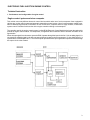

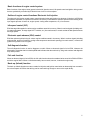

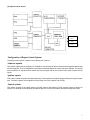
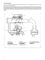
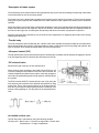
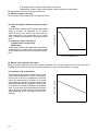
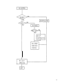
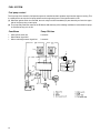
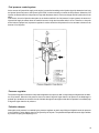
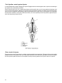

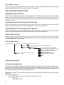
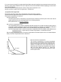

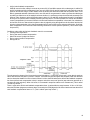
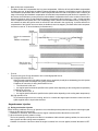
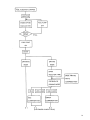
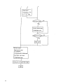
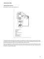
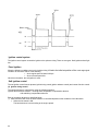
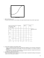
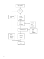
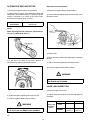
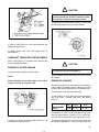
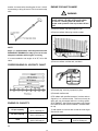

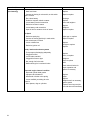
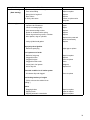

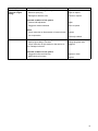
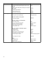
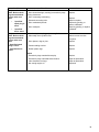
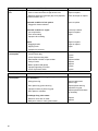

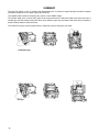

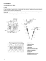
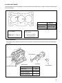
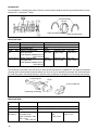
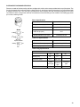

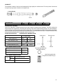
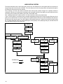
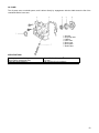
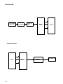
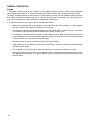
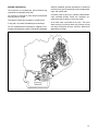

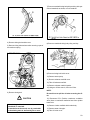
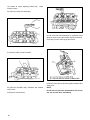

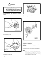

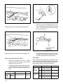
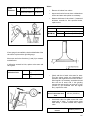
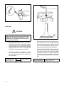
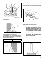
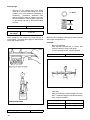
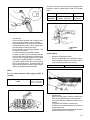
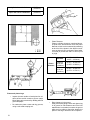
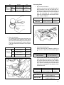
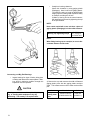
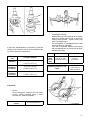
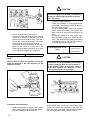

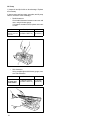
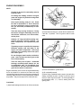
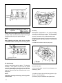

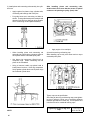
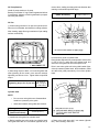
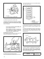
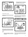

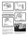
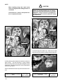
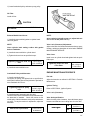
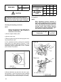
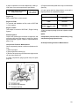
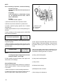

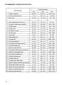
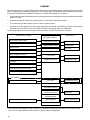
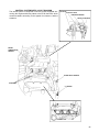
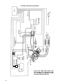
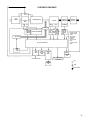
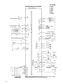
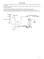


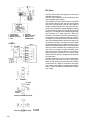

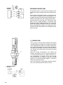


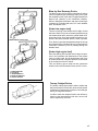


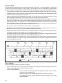

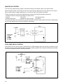
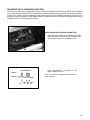


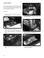
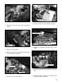
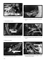
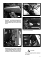


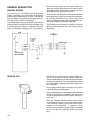
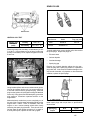
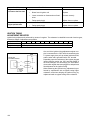
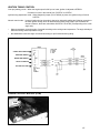


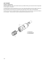
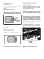
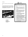
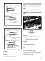

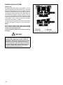
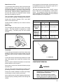
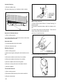
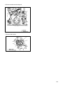
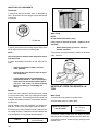
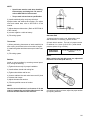
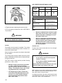


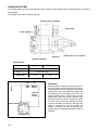
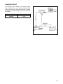
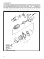
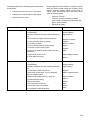
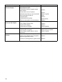
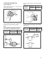

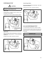


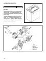
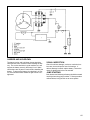
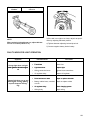

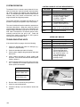
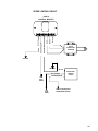


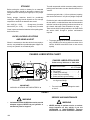

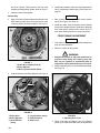
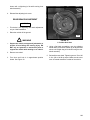
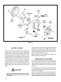
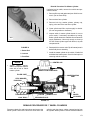
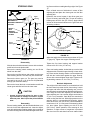
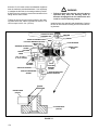
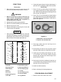
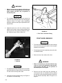
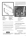
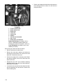
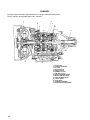
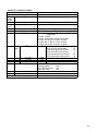
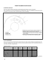
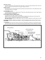
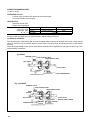

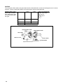
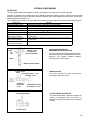
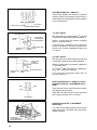


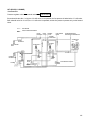
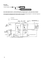
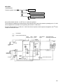
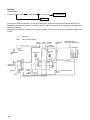
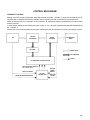
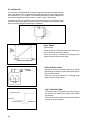
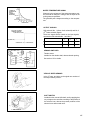
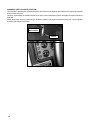


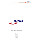

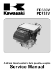
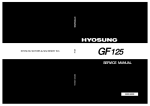
![PC755BM8 [Preliminary]](http://vs1.manualzilla.com/store/data/005786860_1-ac3ee01c2b00aeb18fc7f0a57a841c91-150x150.png)