1
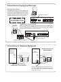
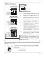
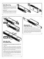
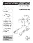
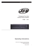
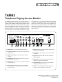
TAMB2
Telephone Paging Access Module
1
TRUNK MODE
LOOP START
PRE ANN TN
VOX ENABLE
ANS IMMED
DETECT CPC
NO TIMER
0
N
O
1
STATION
GND START
CONF TN
VOX DIS
1-RNG DLY
IGNORE
TRNK TMER
The TAMB2 telephone paging access module provides a
means of interfacing various analog telephone port types to
a paging system amplifier to enable a facilityʼs telephone system
to be used to make audio announcements over its paging
system. The TAMB2 will interface to analog loop start and
ground start trunk ports as well as analog ring-up station lines.
It provides a means of connecting an external audio or music
source that will play over the paging system when no pages
1
2
3
4
5
6
7
TAMB2 TELEPHONE PAGING ACCESS MODULE
RANGE (SEC)
1
0
1
0
1<INHIBIT
1<100 - 200
0<50 - 100
0<1 - 50
8
9
are in progress. A set of contacts are provided to signal external
equipment of the TAMB2ʼs operational status. Various DIP
switches and controls provide a wide range of flexibility over
how the access module will operate. The TAMB2 can be
mounted on a wall, mounted as a single unit in a rack (optional
rack mount kit required) or mounted 2-up, side-by-side in a
single rack space.
PAGING
TIME
VOX
DELAY
TONE
MUSIC
MIN MAX
TIME TIME
1s
0
0
6
STATION/
TRUNK
CONTACT
CLOSURES
24VDC
150mA
ON
0
11s
10
10
T
1
PAGE
OUT
2
3
4
5
6
7
1. DIP Switches - Set various operational functions.
2. On/Power Indicator - When lit, indicates that the unit
is powered on.
3. Paging Time Control - Sets maximum time duration
of a page.
4. VOX Delay Control - Sets maximum silence period
allowed for an active page.
5. Tone Control - Sets the level of an announcement tone
the unit produces.
6. Music Control - Sets the level of an external audio
source that plays through the paging system when
no page is active.
R
8
PT PR G/S NO C
9
10
11
NC
12
7. Music Input - Hi-impedance unbalanced RCA input
for stereo or mono signals.
8. Station/Trunk - Tip and ring connections to a PBX
or CO line.
9. Page Out - Balanced, 600-ohm audio feed to the
paging amplifier.
10. G/S Terminal - Provides ground return from PBX
when using a ground start trunk port.
11. Contact Closures - One C-form contact set which
changes state when unit is active.
12. 24V DC - User-supplied power supply input; unit
must be powered in all modes of operation.
© 2010 Bogen Communications, Inc. All rights reserved.
Specifications subject to change without notice.
54-2190-02C 1101
Notice
Important Safety Information
Every effort was made to ensure that the information in this manual
was complete and accurate at the time of printing. However, information is subject to change.
Always follow these basic safety precautions when installing and
using the system:
1.Read and understand all instructions.
FCC Statement (Part 15) - Radio Frequency Interference
2.Follow all warnings and instructions marked on the product.
This unit generates and uses radio frequency energy and if not installed and used in strict accordance with the manufacturer's instructions, may cause interference to radio and television reception.
Testing is being conducted for compliance with the limits for a Class
B device in accordance with the specifications in Part 15 of the FCC
Rules and Canadian D.O.C. regulations. This testing is designed to
provide reasonable protection against such interference. However,
there is no guarantee that interference will not occur in a particular
installation. If this equipment does cause interference to radio or television reception, which can be determined by turning the unit off
and on, the user is encouraged to try to correct the interference by
one or more of the following measures:
3.DO NOT block or cover the ventilation slots and openings. They
prevent the product from overheating. DO NOT place the product
in a separate enclosure or cabinet, unless proper ventilation is
provided.
- Reorient the radio or TV receiving antenna.
- Relocate the unit with respect to the radio or TV receiver or
vice versa.
- Plug the unit into a different outlet so that it and the radio or
TV receiver are on different branch circuits.
If necessary, the user should consult the dealer or an experienced
radio/television technician for additional suggestions. The user may
find the following booklet, "How To Identify and Resolve Radio-TV
Interference Problems," helpful. This booklet was prepared by the
Federal Communications Commission (FCC) and is available from
the U.S. Government Printing Office, Washington, DC 20402. Stock
order No. 004-000-00345-4.
Federal Communications Commission (FCC) Statement
(Part 68)
This equipment is component registered with the Federal Communications Commission (FCC) in accordance with Part 68 of its rules.
In compliance with the rules, be advised of the following:
Registered equipment may not be used with Coin Telephone Lines.
Equipment may be used with Party Lines in areas where state tariffs
permit such connections and when equipment is adaptable for such
service.
This equipment is registered as follows:
Registration Number - US: CD2PA13BTAMB2
Ringer Equivalence - 1.3B
If trouble is experienced, the equipment should be disconnected from
the interface to determine if this equipment, or the telephone line, is
the trouble source. If the equipment is determined to be malfunctioning, it should not be reconnected until repairs are effected.
Repairs to this equipment, other than routine repairs, can be made
only by the manufacturer or its authorized agents.
If the equipment causes harm to the telephone network, the local
telephone company may temporarily discontinue your service and, if
possible, notify you in advance. If advance notice is not practical, you
will be notified as soon as possible. You will be given the opportunity
to correct the problem and informed of your right to file a complaint
with the FCC.
The local telephone company may make changes in its facilities,
operations, or procedures that could affect the proper functioning of
your equipment. If they do, you will be given adequate notice in writing to allow you an opportunity to maintain uninterrupted telephone
service.
4.Never spill liquid on the product or drop objects into the ventilation slots and openings. Doing so may result in serious damage
to the components.
5.Repair or service must be performed by a factory authorized repair facility.
6.The product is provided with a UL-CSA approved, 3-wire ground
type plug. This is a safety feature. DO NOT defeat the safety purpose of the grounding type plug. DO NOT staple or otherwise attach the AC power supply cord to building surfaces.
7.DO NOT use the product near water or in a wet or damp place
(such as a wet basement).
8.DO NOT use extension cords. The product must be installed
within 6 feet of a grounded outlet receptacle.
9.DO NOT install telephone wiring during a lightning storm.
10.DO NOT install telephone jacks in a wet location unless the jack
is specifically designed for wet locations.
11. Never touch uninsulated wires or terminals, unless the line has
been disconnected at the paging or controller interface.
12.Use caution when installing or modifying paging or control lines.
CAUTION
RISK OF ELECTRIC SHOCK
DO NOT OPEN
CAUTION: TO PREVENT THE RISK OF ELECTRIC
SHOCK, DO NOT REMOVE ANY FRONT/BACK
COVERS OR PANELS. NO USER-SERVICEABLE
PARTS INSIDE.
REFER SERVICING TO QUALIFIED PERSONNEL.
The lightning flash with arrowhead symbol,
within an equilateral triangle, is intended to
alert the user to the presence of uninsulated
"dangerous voltage" within the product's
enclosure that may be of sufficient magnitude to constitute a risk of electric shock to
persons.
The exclamation point within an equilateral
triangle is intended to alert the user to the
presence of important operating and maintenance (servicing) instructions.
Theory of Operation
Loop Start Interfacing:
The TAMB2 provides a 24V DC talk battery on its T (tip) and
R (ring) terminals. When it detects a DC loop current flow
through these terminals, it will activate. Upon activation, it will
produce an announcement tone and connect in the paging
amplifier through an isolation transformer. The announcement
tone can be set to be heard only at the paging phone or at both
the phone and over the paging system. The TAMB2 allows
bi-directional audio, both to and from the paging equipment
(in the case of talkback paging equipment). Disconnection of
the page happens when the loop start trunk goes on hook and
loop current flow stops. In this mode, the TAMB2 responds to
the status of the loop current flow and generally no timers are
needed to control when it disconnects. However, a Trunk Timer
feature is provided that can help prevent accidental lock-up of
the paging system (see featureʼs description below).
Ground Start Interfacing:
In addition to the tip and ring connections to this port, an
additional connection between the TAMB2ʼs G/S terminal and
the PBX ground must be established. When idle, the TAMB2
opens an internal relay contact in series with its T (tip) terminal,
and monitors for loop current flowing in its R (ring) terminal.
When the PBX grounds the TAMB2ʼs R terminal, loop current
flows and is detected. The TAMB2 responds by closing the
relay contact in series with its T terminal. Once this connection
is established, the TAMB2 will produce an announcement tone
and connect in the paging amplifier through an isolation transformer. The announcement tone can be set to be heard only at
the paging phone or at both the phone and over the paging
system. The TAMB2 allows bi-directional audio, both to and
from the paging equipment (in the case of talkback paging
equipment). Disconnection of the page happens when the
ground start trunk goes on hook and loop current stops. In this
mode, the TAMB2 responds to the status of the loop current
flow and generally no timers are needed to control when it disconnects. However, a Trunk Timer feature is provided that can
help prevent accidental lock-up of the paging system (see
featureʼs description below).
Trunk Timer Feature:
When interfacing to either loop or ground start trunks, a Trunk
Timer feature can be enabled which will interrupt loop current
flow to the PBX port for 1 second after either the VOX or
Default time has expired. In many PBX systems this break in
loop current will cause the connection between the TAMB2
and the calling station to be cleared, allowing another caller to
access the paging system. This is designed to protect the
paging system from a phone that may have been hung up
incorrectly and is locking out access to the paging system.
In addition to enabling this feature, the Default time period must
be set and/or the VOX timer must be enabled and its time set.
Both timers do not have to be used, but at least one must be
enabled for this feature to work.
Station Port Interfacing:
The TAMB2 answers the station port after it detects high
voltage (90V) ring on the line. The unit can be set to answer
the call immediately or after the end of the first ring burst. Once
answered, the unit provides an announcement tone and connects the telephone line to the paging amplifier through an isolation transformer. The announcement tone can be set to be
heard only at the paging phone or at both the phone and over
the paging system. The TAMB2 allows bi-directional audio,
both to and from the paging equipment (in the case of talkback paging equipment). Since the TAMB2 cannot directly
determine the state of the calling partyʼs phone, it must use
indirect methods to determine when to disconnect. Disconnection of the TAMB2 from the call is controlled through 3
methods. 1) A default timer will drop the call after a preset
amount of time has elapsed (1-200 seconds), 2) A VOX timer
will drop the call after it detects no audio for a preset amount
of time (1-11 seconds), 3) The unit will immediately drop the
line if it detects a CPC pulse (break in loop current) from the
PBX/CO port. Any of these disconnection methods can be inhibited, however at least one must be enabled to ensure that
the TAMB2 will disconnect.
Connections to Paging Amplifier Input
Balanced Input Wiring:
The TAMB2 was designed to connect to a 600-ohm balanced TEL input. The amplifierʼs input sensitivity should
be high enough that with 200mV input signal, the amp
will be able to produce its full rated output power. If input
sensitivity is not high enough, try using an unbalanced
input with a WMT1A transformer (as shown below).
STATION/
TRUNK
T
R
PAGE
OUT
600-ohm Balanced Input
PT PR G/S
IMPORTANT
Keep Amp turned off until all
wiring to the TAMB2 is complete
Unbalanced, Hi-Z Input Wiring:
STATION/
TRUNK
T
R
PAGE
OUT
Wiring to an unbalanced Hi-Z or AUX input normally requires the use of a WMT1A transformer. The output levels of the TAMB2 generally cannot drive this type of input to full rated
power since the AUX input is less sensitive than the specialized TEL inputs. The WMT1A
provides about a 5X voltage increase in the ampʼs input.
PT PR G/S
Hi-Z Unbalanced Input
WMT1A
Impedance-Matching Transformer
Connections to Telephone Equipment
PBX Ground Start Trunk
Port Connections
PBX or CO
PBX
(Loop Start
or Station Port)
(Ground Start Port)
Ring
Tip
STATION/
TRUNK
T
R
PAGE
OUT
PT PR G/S
Ring
Tip
STATION/
TRUNK
T
R
PAGE
OUT
PT PR G/S
PBX Loop Start Trunk Port
CO/PBX Station Port Connections
Wiring to the ground start trunk port requires a connection
between the TAMB2ʼs G/S terminal and the ground of the
PBX. The AC chassis ground for the PBX can typically be
used for this connection.
Connections to a Music Source
AUDIO OUT
L
MUSIC SOURCE
R
The TAMB2ʼs Music Input will combine a stereo signal into mono or a mono source can be connected to either of the two
RCA jacks. The MUSIC control is used to set the level of the music source when playing through the paging system. Set
the level of the page using the amplifierʼs level control, then use the TAMB2 music control to set the background music level.
IMPORTANT NOTE: When using the TAMB2 in ground start trunk mode with a music source that uses a 3-prong
grounded plug, it may be necessary to use WMT1A transformers to isolate the music sourcesʼ outputs from the TAMB2ʼs
music inputs. The music sourceʼs signal ground, which may be connected to the the AC line ground, could create an electrical short with the connection from the TAMB2ʼs G/S terminal to the PBX ground (which is typically the AC ground for the
PBX) causing the TAMB2 not to function.
Power Supply Connections
24VDC
150mA
24VDC
150mA
or greater
(user supplied)
All operational modes of the TAMB2 require the connection of a usersupplied 24V DC power supply. The connection polarity is marked on the
unit. The supply input is polarity-protected so that reversed polarity will
not damage the unit, but it will not operate until the condition is corrected.
When using multiple TAMB2ʼs in an installation, it may be more convenient to use a single, user-supplied power supply and wire the
power terminals of the multiple units together. When doing this, make
sure the power supply is 24V DC and can supply 0.15A x the units
being powered.
Rotary Control Functions
PAGING TIME
This control is used to set the maximum paging time within the Paging Time Range
set by DIP switches 8 & 9. MIN Time is the lowest time of the selected range, MAX
Time is the longest time. The control is linear and the “tick” marks represent 5 or 10
second (approx.) intervals, depending on range set, to make setting a specific time
simple. The Paging Timer can be inhibited.
VOX DELAY
This control sets the period of silence that must elapse for the unit to determine that
paging activity has likely ended. The “tick” marks represent 1-second (approx.)
intervals. This timer can be inhibited.
TONE
This control sets the level of the audible tone that indicates that the paging
connection has been established. The tone cannot be inhibited, but the volume can
be turned down so it cannot be heard.
MUSIC
This control sets the level of an external audio source feeding the paging amplifier
when no page is active.
STATION
GND START
CONF TN
VOX DIS
1-RNG DLY
IGNORE
TRNK TMER
DIP Switch Settings
Set switches in black as indicated.
Other switches are at installer’s discretion.
0
1
N
O
1
0
1
2
3
4
5
6
7
8
N
O
LOOP START TRUNK
TRUNK MODE
LOOP START
PRE ANN TN
VOX ENABLE
ANS IMMED
DETECT CPC
NO TIMER
1
3
4
5
6
7
8
9
ON
0
DIP SW #
VOX TIMER ENABLE
See DIP Switch #4 description
TRUNK TIMER
See DIP Switch #7 description
Sets unit for either Station access or Trunk (Loop Start
and Ground Start) access.
2
Determines if Loop Start or Ground Start trunk access
will be used.
3
Determines if a Pre-Announce tone is to be heard in
handset and paging speakers (set to 0) or if a Confirmation
tone is to be heard in handset only (set to 1).
4
Determines if the VOX timer will operate. Set to 0 to
enable the VOX Timer, or 1 to Disable. Only applies to
Station Access mode or Trunk Timer feature use.
5
Sets unitʼs delay before answering a station access
page to immediate answer (set to 0), or to answer after
1st ring burst (set to 1), (station mode only).
6
Sets unit to detect (set to 0), or ignore CPC pulse (set to 1).
A CPC pulse is issued by certain equipment when the
calling party has hung up (station mode only).
7
Determines if the Trunk Timer function will be used (set
to 0), or not used (set to 1). See Trunk Timer Features
section for description of function.
8/9
Switches 8 / 9 are used together to set the range for
the Paging Time control or to disable the Paging Default
timer, 0/0 = 1- 50 sec, 1/0 = 50 -100 sec, 0/1 = 100 -200
sec, and 1/1 inhibits the timer.
GROUND START TRUNK
Set switches in black as indicated.
Other switches are at installer’s discretion.
1
2
3
4
5
6
7
8
9
N
O
ANNOUNCEMENT TONE
See DIP Switch #3 description
VOX TIMER ENABLE
See DIP Switch #4 description
TRUNK TIMER
See DIP Switch #7 description
TIMER RANGE
See DIP Switch #8/9 description
STATION ACCESS
Set switches in black as indicated.
Other switches are at installer’s discretion.
1
2
3
4
5
6
N
O
ANNOUNCEMENT TONE
See DIP Switch #3 description
VOX TIMER ENABLE
See DIP Switch #4 description
7
8
DIP Switch Function
1
TIMER RANGE
See DIP Switch #8/9 description
1
0
2
1<INHIBIT
1<100 - 200
0<50 - 100
0<1 - 50
9
ANNOUNCEMENT TONE
See DIP Switch #3 description
1
0
1
RANGE (SEC)
1
0
1
0
9
ANSWER DELAY
See DIP Switch #5 description
IMPORTANT NOTE: DO NOT inhibit all of these disconnect features at
CPC DETECTION
See DIP Switch #6 description
once. One of the 3 methods for the TAMB2 to disconnect from a station
port must be enabled. If you disable both timers and the
CPC-detection, or the PBX/CO does not issue CPC pulses when the calling party hangs up, there will be no means for the TAMB2 to
disconnect from the call. You will need to cycle the DC power to the
TAMB2 to disconnect the call.
TIMER RANGE
See DIP Switch #8/9 description
Contact Closures
The contact closure contact set is provided to signal to external equipment the TAMB2ʼs
operational state. The contact set is single pole, double throw, and changes state from what
is screened below the terminals when the TAMB2 becomes active and returns when the unit
becomes idle again.
Contact Ratings: 0.6A @ 125V AC resistive
0.6A @ 110V DC resistive
2.0A @ 30V DC resistive
Wall Mounting
Wall Mount 1 - Insert mounting screws through
mounting brackets and into the side/rear screw
openings as shown. Once the brackets have been
secured, the unit can now be affixed to a wall or
other flat surface.
1
2
Wall Mount 2 - The unit can also be secured
to a wall or flat surface with the front face pointing
upwards to provide less cantilever. Insert mounting screws through mounting brackets as shown.
A
UNIT 1
B
STEP 1
C
UNIT 2
Single Unit
Rack Mounting
For installing a unit into a single rack space,
an RPK91 rack mounting kit is needed (sold separately).
C
UNIT 1
STEP 2
E
D
UNIT 2
Side-By-Side
Rack Mounting
For installing two units into a single rack space, you will use the
mounting brackets of both units to ultimately connect them into one
combined unit.
In STEP 1, start by attaching a mounting bracket onto the left/front
side of Unit 1 as shown in figure A. Then attach a mounting bracket
to the right/rear side of Unit 1, in a reverse manner, as shown in figure B. Then proceed to attach mounting brackets to both the left and
right/front sides of Unit 2, as shown in figure C.
In STEP 2, bring both Unit 1 and Unit 2 flush together. Attach the
units by first inserting screws through the right/rear mounting bracket
on Unit 1 and into the rear of Unit 2, as shown in figure D. Then
insert screws through the left/front bracket on Unit 2 into the front of
Unit 1, as shown in figure E.
The side brackets can be mounted at the back end of the unit if
a rear facing orientation is desired.
Insert mounting screws through the RPK91 mounting brackets and
into the side/rear screw openings as shown. Once the brackets
have been secured, the unit can now be attached to the rack. The
side brackets can be mounted at the back end of the unit if a rear
facing orientation is desired.
Specifications
Registration Number:
Ringer Equivalence:
Station Port Compatibility:
Trunk Port Compatibility:
Paging Frequency Response:
Input/Output Impedance:
Power Requirements:
Pre-announce/Confirmation Tones:
Default Disconnect Timer:
VOX Disconnect Timer:
Auxiliary Contact Rating:
Operating Temperature Range:
Connection Method:
Finish:
Dimensions:
Shipping Weight:
US: CD2PA13BTAMB2
1.3B
Two-wire ring start
Two-wire loop start or ground start
200 – 8000 Hz, ±1 dB
600 ohms, nominal
24V DC @ 150mA (user-supplied)
800 Hz, ±20%, one-half second duration
1 to 200 seconds, adjustable or inhibit
1 to 11 seconds, adjustable or inhibit
0.6A @ 125V AC resistive
0.6A @ 110V DC resistive
2.0A @ 30V DC resistive
32° – 120°F.
Screw terminal
Black enclosure with white lettering
8-1/2" W x 1-3/4" H x 3" D
2 lb.
Limited Warranty; Exclusion of Certain Damages
The Bogen TAMB2 Telephone Access Module is warranted to be free from defects in material and workmanship for two (2) years from the
date of sale to the original purchaser. Any part of the product covered by this warranty that, with normal installation and use, becomes defective (as confirmed by Bogen upon inspection) during the applicable warranty period, will be repaired or replaced by Bogen, at Bogen’s option, provided the product is shipped insured and prepaid to: Bogen Factory Service Department, 50 Spring Street, Ramsey, NJ 07446, USA.
Repaired or replacement product will be returned to you freight prepaid. This warranty does not extend to any of our products that have been
subjected to abuse, misuse, improper storage, neglect, accident, improper installation or have been modified or repaired or altered in any
manner whatsoever, or where the serial number or date code has been removed or defaced.
THE FOREGOING LIMITED WARRANTY IS BOGEN’S SOLE AND EXCLUSIVE WARRANTY AND THE PURCHASER’S SOLE AND
EXCLUSIVE REMEDY. BOGEN MAKES NO OTHER WARRANTIES OF ANY KIND, EITHER EXPRESS OR IMPLIED, AND ALL IMPLIED
WARRANTIES OF MERCHANTABILITY OR FITNESS FOR A PARTICULAR PURPOSE ARE HEREBY DISCLAIMED AND EXCLUDED
TO THE MAXIMUM EXTENT ALLOWABLE BY LAW. Bogen's liability arising out of the manufacture, sale or supplying of products or their
use or disposition, whether based upon warranty, contract, tort or otherwise, shall be limited to the price of the product. IN NO EVENT SHALL
BOGEN BE LIABLE FOR SPECIAL, INCIDENTAL OR CONSEQUENTIAL DAMAGES (INCLUDING, BUT NOT LIMITED TO, LOSS OF
PROFITS, LOSS OF DATA OR LOSS OF USE DAMAGES) ARISING OUT OF THE MANUFACTURE, SALE OR SUPPLYING OF PRODUCTS, EVEN IF BOGEN HAS BEEN ADVISED OF THE POSSIBILITY OF SUCH DAMAGES OR LOSSES. Some States do not allow the
exclusion or limitation of incidental or consequential damages, so the above limitation or exclusion may not apply to you. This warranty gives
you specific legal rights, and you may also have other rights which vary from State to State.
Products that are out of warranty will also be repaired by the Bogen Factory Service Department – same address as above or call 201-934-8500.
The parts and labor involved in these repairs are warranted for 90 days when repaired by the Bogen Factory Service Department. All shipping
charges in addition to parts and labor charges will be at the owner's expense. All returns require a Return Authorization number. For most
efficient warranty or repair service, please include a description of the failure.
12/2008
50 Spring Street, Ramsey, NJ 07446, U.S.A.
Tel. 201-934-8500 • Fax: 201-934-9832
www.bogen.com