1
Device Management with Wavelink Avalanche® Enabler
User’s Guide
Disclaimer
Honeywell International Inc. (“HII”) reserves the right to make changes in specifications and other information contained in this
document without prior notice, and the reader should in all cases consult HII to determine whether any such changes have been
made. The information in this publication does not represent a commitment on the part of HII.
HII shall not be liable for technical or editorial errors or omissions contained herein; nor for incidental or consequential damages
resulting from the furnishing, performance, or use of this material.
HII disclaims all responsibility for the selection and use of software and/or hardware to achieve intended results.
This document contains proprietary information that is protected by copyright. All rights are reserved. No part of this document
may be photocopied, reproduced, or translated into another language without the prior written consent of HII.
© 2004-2014 Honeywell International Inc. All rights reserved.
Web Address: www.honeywellaidc.com
Trademarks
RFTerm is a trademark or registered trademark of EMS Technologies, Inc. in the United States and/or other countries.
Microsoft® Windows®, ActiveSync®, Windows XP®, MSN, Outlook®, Windows Mobile®, the Windows logo, and Windows Media
are registered trademarks or trademarks of Microsoft Corporation in the United States and/or other countries.
Summit Data Communications, Inc. Summit Data Communications, the Summit logo, and “The Pinnacle of Performance” are
trademarks of Summit Data Communications, Inc.
The Bluetooth® word mark and logos are owned by the Bluetooth SIG, Inc.
Wavelink®, Wavelink Avalanche®, the Wavelink logo and tagline, Wavelink Studio™, Avalanche Management Console™, Mobile
Manager™, and Mobile Manager Enterprise™ are trademarks of Wavelink Corporation, Kirkland.
Patents
For patent information, please refer to www.hsmpats.com.
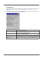
Table of Contents
Chapter 1 - Introduction
Overview ..............................................................................................................................1-1
The Avalanche Enabler Process..........................................................................................1-1
Avalanche MC Console..................................................................................................1-2
eXpress Config.........................................................................................................1-2
Avalanche Mobile Device Server ...................................................................................1-2
Avalanche Enablers .......................................................................................................1-2
Remote Management Utility (RMU) .........................................................................1-2
Avalanche Remote Control ............................................................................................1-3
Device Skins ............................................................................................................1-3
eXpress Scan.................................................................................................................1-3
Supported Devices.........................................................................................................1-3
HX2 ..........................................................................................................................1-3
HX3 ..........................................................................................................................1-3
MX3Plus ...................................................................................................................1-3
MX7 Tecton ..............................................................................................................1-3
MX7 ..........................................................................................................................1-3
MX8 ..........................................................................................................................1-4
MX9 ..........................................................................................................................1-4
Thor VM1 .................................................................................................................1-4
Thor VM2 .................................................................................................................1-4
VX3Plus ...................................................................................................................1-4
VX6 ..........................................................................................................................1-4
VX7 ..........................................................................................................................1-4
Chapter 2 - Enabler Installation and Configuration
Introduction ..........................................................................................................................2-1
Installation............................................................................................................................2-1
Installing the Enabler on Mobile Devices .......................................................................2-1
VX6/VX7 Enabler Installation ...................................................................................2-1
Enabler Uninstall Process ..............................................................................................2-2
Stop the Enabler Service ...............................................................................................2-2
Update Monitoring Overview..........................................................................................2-2
Mobile Device Wireless and Network Settings...............................................................2-3
Preparing a Device for Remote Management................................................................2-3
Using Wavelink Avalanche to Upgrade System Baseline ........................................2-3
Part 1 – Bootstrapping the RMU ........................................................................2-4
Part 2 – Installing Packages...............................................................................2-4
Version Information on Mobile Devices..............................................................2-4
User Interface ......................................................................................................................2-4
Parameters and Screen Displays...................................................................................2-4
Enabler Configuration ..........................................................................................................2-5
File Menu Options ..........................................................................................................2-5
Avalanche Update using File > Settings ........................................................................2-5
Menu Options ...........................................................................................................2-6
1
Connection............................................................................................................... 2-7
Server Contact......................................................................................................... 2-8
Data ......................................................................................................................... 2-9
Preferences ........................................................................................................... 2-10
Administration .................................................................................................. 2-10
Application ....................................................................................................... 2-10
Activity Log....................................................................................................... 2-10
Display ................................................................................................................... 2-11
Update Window Display................................................................................... 2-11
Taskbar.................................................................................................................. 2-12
Execution ............................................................................................................... 2-13
Scan Config ........................................................................................................... 2-14
Shortcuts................................................................................................................ 2-15
SaaS ...................................................................................................................... 2-16
Adapters ................................................................................................................ 2-17
Status..................................................................................................................... 2-20
Startup/Shutdown .................................................................................................. 2-21
Exit......................................................................................................................... 2-22
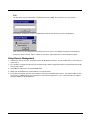
Using Remote Management.............................................................................................. 2-22
Using eXpress Scan .......................................................................................................... 2-23
Step 1: Create Bar Codes............................................................................................ 2-23
Step 2: Scan Bar Codes .............................................................................................. 2-23
Step 3: Process Completion ........................................................................................ 2-24
Chapter 3 - Avalanche Mobility Center Console
Introduction.......................................................................................................................... 3-1
Installation ........................................................................................................................... 3-1
Avalanche Mobility Center Console Components ............................................................... 3-1
Software Profiles ................................................................................................................. 3-2
Network Profiles............................................................................................................. 3-3
Network Settings...................................................................................................... 3-4
Mobile Device Inventory .......................................................................................... 3-5
Mobile Device Groups ................................................................................................... 3-6
Mobile Device Details .................................................................................................... 3-6
Chapter 4 - eXpress Config
Introduction.......................................................................................................................... 4-1
Avalanche Software Collections .................................................................................... 4-1
Space Requirements on Mobile Computers .................................................................. 4-1
Installation ........................................................................................................................... 4-2
Prerequisites.................................................................................................................. 4-2
Install eXpress Config.................................................................................................... 4-2
Uninstall eXpress Config ............................................................................................... 4-2
2
Creating a Software Package with eXpress Config............................................................. 4-2
Prerequisites:................................................................................................................. 4-2
Process Overview.......................................................................................................... 4-3
Important Note for Software Packages Containing an Operating System..................... 4-3
Package Selection Screen............................................................................................. 4-3
Updating Many Devices With The Same Configuration................................................. 4-4
Procedure for Removing Package Files on the Remote Device.................................... 4-4
Configuring a Software Package with eXpress Config ........................................................ 4-4
Menu Bar ....................................................................................................................... 4-5
File Menu ................................................................................................................. 4-5
Edit Menu................................................................................................................. 4-5
Navigation Tree ............................................................................................................. 4-5
Controls ................................................................................................................... 4-6
Root Nodes.............................................................................................................. 4-6
Reboot Options .................................................................................................. 4-6
Data File Options ............................................................................................... 4-6
Configuration Panel ....................................................................................................... 4-7
Controls ................................................................................................................... 4-7
Component Parameters................................................................................................. 4-8
Creating Configuration Bar Codes with eXpress Config...................................................... 4-9
Process Overview.......................................................................................................... 4-9
Menu Bar ..................................................................................................................... 4-10
File Menu ............................................................................................................... 4-10
Edit Menu............................................................................................................... 4-10
Barcodes Menu...................................................................................................... 4-10
Navigation Tree ........................................................................................................... 4-11
Controls ................................................................................................................. 4-12
Root Nodes............................................................................................................ 4-12
Data File Options ............................................................................................. 4-12
Configuration Panel ..................................................................................................... 4-12
Controls ................................................................................................................. 4-13
Component Parameters............................................................................................... 4-14
Chapter 5 - Avalanche Remote Control
Introduction.......................................................................................................................... 5-1
Supported Devices .............................................................................................................. 5-1
Installation ........................................................................................................................... 5-1
Remote Control Console ..................................................................................................... 5-1
Skins .............................................................................................................................. 5-1
Adding a Device to Remote Control .............................................................................. 5-2
Selecting an Alternative Skin ......................................................................................... 5-4
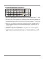
Remote Control Keypad Limitations .................................................................................... 5-6
All Devices ..................................................................................................................... 5-6
HX2 Dual Alpha ............................................................................................................. 5-7
HX2 Triple Tap............................................................................................................... 5-7
HX2 Legacy ................................................................................................................... 5-8
Physical Keypad ...................................................................................................... 5-8
3
Remote Control Keypad .......................................................................................... 5-8
HX3................................................................................................................................ 5-9
MX7-55 .......................................................................................................................... 5-9
MX7-32 ........................................................................................................................ 5-10
MX8 ............................................................................................................................. 5-11
VX6 .............................................................................................................................. 5-11
VX7 60-key Standard Keypad (Small QWERTY) ........................................................ 5-12
VX7 95-key Keyboard (Large QWERTY) .................................................................... 5-13
Chapter 6 - Customer Support
Product Service and Repair................................................................................................. 6-1
Technical Assistance........................................................................................................... 6-1
Limited Warranty ................................................................................................................. 6-1
4
1
Introduction
Overview
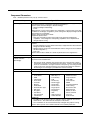
\Wavelink® Avalanche Mobility Center™ (Avalanche MC) is a remote client management system that is designed to distribute
software and configuration updates to monitored devices, including Honeywell computers with Microsoft® Windows® CE or Windows Mobile®. Additionally, the Avalanche MC Console may provide support for other devices on a network at the discretion of
the system administrator.
Avalanche uses a multi-tier software architecture:
• Avalanche Mobility Center Console (Avalanche Management Console in previous versions)
• Avalanche Mobile Device Server (Avalanche Agent in previous versions)
• Avalanche Enabler
• Avalanche Remote Control (optional component)
Avalanche Mobility Center Console and the Avalanche Mobile Device Server run on a desktop PC.
Avalanche Enabler runs on the monitored devices.
This document contains a brief overview of Avalanche MC and how Honeywell computers can be managed by Avalanche MC.
Honeywell provides additional functionality for mobile computers using Avalanche MC. This additional functionality is discussed
in this guide.
This document also explains the functioning of the Wavelink Avalanche Enabler running on a mobile device.
This document assumes the user has a basic familiarity with the Wavelink Avalanche MC system and Microsoft Office Windows
terms and graphical standards. For detailed and technical information for the Avalanche MC Console running on a desktop PC,
refer to the Wavelink Avalanche Mobility Center User’s Guide. This document is available for download from the Wavelink website, www.wavelink.com.
eXpress Config is an Honeywell value-add component for integration with the Avalanche MC Console. eXpress Config enables
the system administrator to create software package files including software configuration parameters. These packages are
compatible with the Avalanche MC Console and the Mobile Device Server downloads these packages to the mobile devices.
Contact Technical Assistance (page 6-1) for eXpress Config availability.
eXpress Config also allows a user to print configuration bar codes for a mobile computer. The bar codes can be scanned by the
eXpress Scan utility on the mobile device to provide initial configuration.
The Avalanche Enabler Process
In the typical installation, the Honeywell computer, or mobile device, is connected wirelessly to an access point.
The access point is then connected via a wired network to the PC running the Avalanche Mobile Device Server.
The Avalanche Enabler, running on the mobile computer, initiates communication with the Mobile Device Server.
This occurs automatically following a mobile device reboot.
Once a connection is made with a Mobile Device Server, the Enabler can be configured to control the wireless and network settings of the mobile device. The Enabler can also receive downloads, from the Mobile Device Server, of any software packages
made available by the system administrator.
The Mobile Device Server PC records the date and time of the contact and reviews the software load and configuration settings
(wireless and network settings and Terminal Emulation parameters) on the Honeywell mobile device. If there are any software
updates or configuration setting changes scheduled for the mobile device, the update is performed at this time.
Once connected to the Avalanche Mobile Device Server, the mobile device Enabler continues running in the background, monitoring and processing updates and system information as needed. The monitoring is performed by a separate application, Monitor.exe, which is installed as part of the Enabler CAB file. The Monitor executable is responsible for locating the Avalanche
Mobile Device Server and processing all updated information. This information can be configured by the system administrator
using the Avalanche MC Console application and then sent to the Mobile Device Server, and then to the mobile computer.
Once the Enabler Monitor receives the data it will apply all new settings, install all software, and provide the user with details,
including any reboots that are needed.
1-1
For Honeywell packages, the Monitor application downloads package files to the RMU folder on the mobile device’s persistent
storage card. The Monitor application then launches the Remote Management Utility (RMU). The RMU performs the updates
for the Honeywell packages. The RMU is also launched during bootup to restore the package’s configuration settings.
Additional functionality of the Enabler can be accessed through a password protected Enabler user interface on the mobile
device. This Enabler functionality, which will be explained in further detail later in this guide, includes:
•
•
•
•
Connection to Mobile Device Server method
Connection parameters to the Mobile Device Server
Start-up parameters
Network and Wireless monitoring and control
Avalanche MC Console
The Avalanche MC Console is a Windows desktop application.
It can be run from any location on the network and can be used with multiple Mobile Device Servers as long as there is an
IP or network connection between the PC with the Avalanche MC Console and the PC (or multiple PCs) running the Mobile
Device Server service.
The Avalanche MC Console and the Mobile Device Server may also be installed on the same PC.
The Avalanche MC Console does not communicate directly with the managed devices. Instead, the Avalanche MC Console communicates with the Mobile Device Server and the Mobile Device Server communicates with the managed devices.
Avalanche MC Console version 4.2 or greater supports the Avalanche Enablers designed for Honeywell mobile devices.
eXpress Config
eXpress Config can be used to create and configure Honeywell software packages for distribution from the Avalanche
MC Console.
Avalanche Mobile Device Server
The Avalanche Mobile Device Server is installed on a desktop or laptop PC and runs/functions as a Windows service. The
Mobile Device Server starts automatically and monitors for communications from devices running Avalanche Enablers that
are connected to the same network.
The Avalanche MC Console can connect to or disconnect from the Mobile Device Server. Even when the Avalanche MC
Console is not connected to the Mobile Device Server, the Mobile Device Server continues to monitor for communications
from the Enablers.
Avalanche Enablers
Avalanche Enablers are installed on the devices to be monitored. The Enabler maintains a record of the software updates
and configuration parameters on the monitored device. This information is communicated to the Mobile Device Server running as a Windows service on a desktop PC. The Mobile Device Server sends updated software and configuration parameters to the monitored devices as applicable.
The Enabler performs several functions:
• Reports revision levels of software currently loaded on the monitored device.
• Receives and installs software and configuration updates from the Mobile Device Server.
• Prompts the User for reboots as necessary during the installation/configuration process.
Remote Management Utility (RMU)
The Honeywell Remote Management Utility (RMU) is installed on all supported Honeywell devices during manufacturing.
The RMU maintains records of all Honeywell packages that have been downloaded to the device. The RMU is
launched by the Enabler each time a package is updated.
The RMU performs several functions:
• Identifies and installs Honeywell packages.
• Applies settings for Honeywell packages configured by eXpress Config.
• Removes Honeywell packages that have been deleted by the Enabler.
1-2
• Updates real-time properties which are communicated back to the Mobility Center Console via the Mobile Device
Server.
Avalanche Remote Control
Avalanche Remote Control is an add-on for Avalanche MC. Remote control provides the administrator the ability to
remotely view the mobile device’s desktop and enter data into the mobile device.
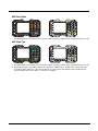
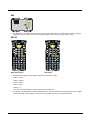
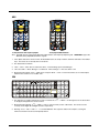
Device Skins
Device skins work with Avalanche Remote Control for supported Honeywell mobile devices. The skins enable Remote
Control to display an image of the Honeywell mobile device being managed. The skin provides:
• An image of the mobile device including the display
• An image of the mobile device keypad. Keypresses performed via Remote Control function the same as if the keys
were pressed on the mobile device.
eXpress Scan
The eXpress Scan utility allows an administrator to scan bar codes to provide the initial network and Avalanche Mobile
Device Server address configuration. This eliminates the need to edit radio parameters manually on the mobile device.
eXpress Scan uses bar codes created with eXpress Config.
Supported Devices
The following Honeywell computers / mobile devices, running the Avalanche Enabler, are supported. They will identify
themselves to the Avalanche Console using the string shown for Model Identifier. Some devices may have more than one
identifier string depending on software revision or hardware configuration. User’s Guides for these devices are available at
www.honeywellaidc.com.
HX2
•
•
•
•
•
The HX2 is obsolete
Microsoft Windows CE 5.0
Intel® XScale® processor, 400MHz
Color display, 320 x 240 pixels
Model Identifier: LXE_HX2
HX3
•
•
•
•
Microsoft Windows CE 5.0
Intel® XScale® processor, 400MHz
No display, minimal keypad
Model Identifier: LXE_HX3
MX3Plus
•
•
•
•
•
•
The MX3 Plus is obsolete
MX3Plus: Microsoft Windows CE 5.0
Intel® XScale® processor, 400MHz
Serial COM port(s) on endcap
Color display, 640 x 240 pixels
Model Identifier: LXE_MX3X or LXE_MX3H
MX7 Tecton
•
•
•
•
•
Microsoft Windows CE 6.0 or Windows Mobile 6.5
Intel® XScale® processor, 806MHz
Serial COM port on base of device
Color display, 240 x 320 pixels
Model Identifier: LXE_MX7T or LXE_MX7TWM
MX7
• The MX7 is obsolete
• Microsoft Windows CE 5.0
• Intel® XScale® processor, 400MHz
1-3
• Serial COM port on base of device
• Color display, 240 x 320 pixels
• Model Identifier: LXE_MX7
MX8
•
•
•
•
•
•
The MX8 is obsolete
Microsoft Windows CE 5.0
Intel® XScale® processor 520MHz
Serial COM port on base of device
Color display, 240 x 320 pixels
Model Identifier: LXE_MX8
MX9
•
•
•
•
•
Microsoft Windows CE 5.0 or Windows Mobile 6.5
Marvell® PXA-320 processor 806MHz
Serial COM port on base of device
Color display, 3.7” (94mm), vertical orientation
Model Identifier: LXE_MX9 or LXE_MX9WM
Thor VM1
•
•
•
•
•
Microsoft Windows CE 6.0
Intel® Atom Z530 processor 1.6GHz
Serial COM ports on Vehicle-Mount Smart Dock
Color display, 8” (20cm), WVGA (800x480)
Model Identifier: LXE_THOR
Thor VM2
•
•
•
•
•
Microsoft Windows CE 6.0
Intel® Atom Z530 processor 1.6GHz
Serial COM ports on Vehicle-Mount Smart Dock
Color display, 8” (20cm), SVGA (1024x768)
Model Identifier: LXE_THOR
VX3Plus
•
•
•
•
•
•
The VX3Plus is obsolete
Microsoft Windows CE 5.0
Intel® XScale® processor, 400MHz
Serial COM port(s) on endcap
Color display, 640 x 240 pixels
Model Identifier: LXE_VX3X or LXE_VX3H
VX6
•
•
•
•
•
•
The VX6 is obsolete
Microsoft Windows CE .NET 4.2 or CE 5.0
Intel® XScale® processor, 400MHz
Serial COM ports at base of device
Half screen color display, 800 x 320 pixels
Model Identifier: LXE_VXC, LXE_VX6 or LXE_VX6SD
VX7
•
•
•
•
•
•
1-4
The VX7 is obsolete
Microsoft Windows CE .NET 4.2 or CE 5.0
Intel® XScale® processor, 400MHz
Serial COM ports at base of device
Full screen color display, 800 x 600 pixels
Model Identifier: LXE_VXC, LXE_VX7 or LXE_VX7SD
2
Enabler Installation and Configuration
Introduction
This section discusses mobile device supported features with Wavelink Avalanche Mobile Device Servers. This section is split
into three basic areas:
• Installation
• User Interface
• Enabler Configuration
Installation
To use the Wavelink Avalanche MC System, the following items are required:
• A desktop or laptop PC on which to install the Avalanche MC Console.
• A desktop or laptop PC on which to install the Avalanche Mobile Device Server (this can be the same PC where the Avalanche
MC Console is installed).
• Wavelink Avalanche MC Console 4.2 or later.
• A Wavelink Device License for each client device.
• Supported mobile devices with Enablers installed, see Supported Devices (page 1-3).
To use Avalanche Remote Control, the follow additional items are required:
• Wavelink Remote Control plug-in, 2.0 or later
• A Wavelink Remote Control License for each client device
Installing the Enabler on Mobile Devices
Supported Devices (page 1-3) have the Avalanche Enabler installation files loaded, but not installed, on the mobile device
when it is shipped. The installation files are located in the \System folder on Windows devices.
Supported devices manufactured before April 2007 must have some software components upgraded before they can use
the Avalanche Enabler functions described in this guide. Contact Technical Assistance (page 6-1) for details on upgrading
the mobile device baseline.
Note: Important: If the user is NOT using Wavelink Avalanche to manage their mobile device(s), the Enabler should not
be installed on the mobile device(s). Doing so results in unnecessary delays when booting the device.
The Avalanche Enabler installation file HSM_ENABLER.CAB is loaded on the mobile device by Honeywell; however, the
device is not configured to launch the Enabler installation file automatically. The installation application must be run manually the first time Avalanche is used.
Note: Older versions of the Enabler may have an LXE_ENABLEER.CAB file or a device specific name such as
LXE_XXX_ENABLER.CAB.
After installation, the Enabler runs as a background application monitoring for updates. This behavior can be modified by
accessing the Avalanche Update Settings panel through the Enabler interface.
The RMU.CE.CAB file is placed on the device during manufacturing in the \System\RMU folder.
During the Enabler installation process, the Enabler checks for the RMU.CE.CAB file in the \System folder.
• If present, it assumes the RMU.CE.CAB file is already installed and continues.
• If the file RMU.CE.CAB file is not present, it looks for the file in the \System\RMU folder.
• If present, the Enabler copies the file to the \System folder and installs it.
At this point, the OS will automatically install the Remote Management Utility (RMU) after the mobile device reboots.
VX6/VX7 Enabler Installation
Because the VX6 and VX7 computers have two possible network adapters (the optional internal adapter for a cabled
network connection and the wireless network card), the Enabler uses the first network adapter it discovers. In order to
assure the Enabler uses the wireless connection, perform one of the following actions:
• Select the Adapters tab in the Enabler setup (See Adapters (page 2-17)) and make sure the wireless adapter is
selected for Current Adapter.
2-1
• To disable the internal network adapter, create a file in the \System directory named NoEther.tag. The contents of
the file are unimportant; but the file must be named NoEther.tag and it must be in the \System directory. (If the
\System directory contains a file named Ether.tag, you can rename this file to NoEther.tag instead of creating a new
file).
• After creating the file, coldboot the device. After the device finishes booting, the internal Ethernet adapter is disabled.
• To restore the adapter, delete the NoEther.tag file and coldboot the device.
Enabler Uninstall Process
To remove the Avalanche Enabler from the mobile device:
• Delete the Avalanche folder located in the \System directory.
• Warm boot the mobile device.
The Avalanche folder cannot be deleted while the Enabler is running. See Stop the Enabler Service (page 2-2).
If sharing errors occur while attempting to delete the Avalanche folder, warm boot the mobile device, immediately delete the
Avalanche folder, and then perform another warm boot.
Stop the Enabler Service
To stop the Enabler from monitoring for updates from the Mobility Center Console:
1. Open the Enabler Settings Panels by tapping the Enabler icon on the mobile device desktop.
2. Select File > Settings.
3. Select the Startup/Shutdown tab.
4. Select the Do not monitor or launch Enabler parameter to prevent automatic monitoring upon startup.
5. Select Stop Monitoring for an immediate shutdown of all Enabler update functionality upon exiting the user interface.
6. Click the OK button to save the changes.
7. Reboot the mobile device if necessary.
or
1. Open the Enabler Settings Panels by tapping the Enabler icon on the mobile device desktop.
2. Select File > Settings.
3. Select the Preferences tab.
4. Select Do not monitor to prevent automatic monitoring upon Startup.
5. Select Exit Application for an immediate shutdown of all Enabler update functionality upon exiting the user interface.
6. Click the OK button to save the changes.
7. Reboot the mobile device if necessary.
Update Monitoring Overview
There are three methods by which the Enabler on the mobile device can communicate with the Mobile Device Server running on the host machine.
• Wired via a serial cable between the Mobile Device Server PC and the mobile device.
• Wired via a USB connection, using ActiveSync, between the Mobile Device Server PC and the mobile device.
• Wirelessly via the mobile device’s 2.4GHz radio and an access point
After installing the Enabler on the mobile device the Enabler searches for a Mobile Device Server, first by polling all available serial ports and then over the wireless network.
The Enabler running on the mobile device will attempt to access COM1, COM2, and COM3. “Agent not found” is reported
if the Mobile Device Server is not located or a serial port is not present or available (COM port settings can be verified using
the bar code wedge panels on the mobile device).
Note: Refer to the equipment specific User’s Guide for communication details as there may be differences in capabilities.
2-2
The wireless connection is made using the default wireless [radio] interface on the mobile device therefore the mobile
device must be actively communicating with the network for this method to succeed.
If a Mobile Device Server is found, the Enabler automatically attempts to apply all wireless and network settings from the
active profile. The Enabler also automatically downloads and processes all available packages.
If the Enabler does not automatically detect the Mobile Device Server, the IP address of the Mobile Device Server can be
entered on the Connect tab of the Enabler setup. Please see Connection (page 2-7) for details.
Mobile Device Wireless and Network Settings
Once the connection to the Mobile Device Server is established, the mobile device Enabler attempts to apply all network
and wireless settings contained in the active profile.
The success of the application of settings is dependent upon the local configuration of control parameters for the Enabler.
These local parameters cannot be overridden from the Avalanche MC Console.
The default Enabler adapter control settings are:
• Manage network settings – enabled
• Use Avalanche network profile – enabled
• Manage wireless settings – disabled
To configure the Avalanche Enabler management of the network and wireless settings:
1. Open the Enabler Settings Panels by tapping the Enabler icon on the desktop.
2. Select File > Settings.
3. Select the Adapters tab.
4. Choose settings for the Use Manual Settings parameter.
5. Choose settings for Manage Network Settings, Manage Wireless Settings and Use Avalanche Network Profile.
6. Click the OK button to save the changes.
7. Reboot the device.
Preparing a Device for Remote Management
Two additional utilities are necessary for remote management. These utilities are included on mobile devices manufactured
after April 2007.
• The Remote Management Utility (RMU) must be installed on all mobile devices first – then you can control mobile
device reboot, storage RAM adjustment, real-time updates and Avalanche Enabler properties.
If in doubt, verify RMU.CE.CAB exists in the \System folder. If the RMU.CE.CAB file is present when the Enabler is
installed, the RMU is also installed.
Important: If the OS package includes double-byte Asian fonts, the storage RAM property of the RMU must be higher than
the default value (40MB).
If the amount of storage RAM is too low, the Enabler returns a “Mobile unit out of resources” error.
To determine the minimum value required, inspect the RMU.StorageRAM>=nn parameter in the Criteria field for the OS
package. Generally, this setting should be approximately 40 MB above the amount of RAM in use on the device for a standard OS and 50MB above the amount of RAM in use for an OS with Asian fonts.
For example, if after installing all the software, the device shows 5MB in use, this setting should be about 45MB for a standard OS, 55 MB for an Asian font OS.
• Use the Wireless Configuration Application (WCA) when you want to remotely manage the Summit client device. This
utility is downloaded and installed in addition to the Remote Management Utility. The WCA is included when the Summit
radio driver software is updated. The WCA is automatically installed when the radio driver is updated.
Using Wavelink Avalanche to Upgrade System Baseline
This procedure assumes the Avalanche Enabler is already installed on the mobile device and is already in communication with the Avalanche MC Console.
2-3
Part 1 – Bootstrapping the RMU
1. Install the RMUCEbt package into the Avalanche MC Console. Do NOT include the Reboot option as part of
the configuration (i.e., the Reboot button in the “Reboot Options” branch must be unbolded).
2. Enable ONLY the RMUCEbt package in the Avalanche MC Console and update the devices. The RMU is
downloaded and automatically installed.
3. Disable the RMUCEbt package in the Avalanche MC Console.
4. For each device, double-click on the device to open the Client Controls dialog box.
5. Check the Delete Orphaned Packages checkbox and click the Update Now button.
6. After the sync completes, uncheck Delete Orphaned Packages and close the dialog box.
Part 2 – Installing Packages
1. Enable the RMUCE package in the Avalanche MC Console.
2. Enable all remaining packages and send them down. It is important that you include the new OS package in
this group (be sure to include the Enabler). If the radio is to be managed remotely, it is important to include
the radio package in this group so that after the reboot the radio can automatically associate. If the radio
package is not sent, the device loses connection to the network and manual configuration of the radio parameters is required.
3. Set the Reboot setting for the OS package to Auto.
4. After all packages are downloaded (this may take several minutes) the Remote Management Utility (RMU) is
launched. The RMU processes all the downloaded packages. If the radio package was downloaded, the
Wireless Configuration Application (WCA) is launched to process the new radio settings.
5. After the RMU finishes installing all the packages, the device is automatically coldbooted (assuming the
Reboot setting was set to Auto in Step 3).
6. After the Device completes the coldboot, the RMU is autoinstalled by the OS and the previously downloaded
packages are restored. Assuming at least one package has registry settings that were restored, and that
package was set to reboot (either auto or prompt), the RMU then performs an automatic warmboot.
7. After the warmboot, the device is configured.
8. If the device will no longer be monitored by Wavelink Avalanche, you may remove the Enabler to eliminate
boot up delays, if desired. Even if the Enabler is removed, the installed packages and their configurations
continue to be restored with every reboot by the RMU.
Version Information on Mobile Devices
The VersionInfo.EXE file is included in the Remote Management Utility package downloaded to the mobile device.
It is stored in the \Program Files\RMU folder. When VersionInfo.EXE is opened, a dialog box is presented to the
device user displaying:
• Remote Management Utility (RMU) version
• Wireless Configuration Application (WCA) version
VersionInfo displays the version for each utility only after that utility has been executed at least once.
User Interface
The Enabler can be configured and controlled manually through the user interface on the mobile device. This section details the
functionality that can be controlled by the user or system administrator.
Parameters and Screen Displays
Screen displays shown in this section are designed to present the end-user with information graphically.
Placement of information on the screen displays may be split between one or many tabbed panels.
Standard Avalanche Enabler parameters that are not supported by Honeywell may be missing or dimmed (visible but
unable to be edited) on the tabbed panels or screen displays.
2-4
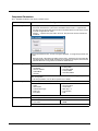
Enabler Configuration
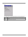
Depending on the version of the Enabler running on the mobile device, the desktop Enabler icon may look like one of the following:
The available configuration options and tabs may vary by Enabler version. The examples shown in this section assume the latest version of the Enabler is installed on the mobile device.
The Enabler user interface application is launched by clicking either the Enabler icon on the desktop or Taskbar or by selecting
Avalanche Enabler from the Programs menu.
The opening screen presents the mobile device user with the connection status and a navigation menu.
Note: Some parameters and features described in this section may not be available if you are not running the latest version of
the Enabler. Contact Technical Assistance (page 6-1) for upgrades.
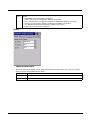
File Menu Options
Connect
The Connect option under the File menu allows the user to initiate a manual connection to the Mobile Device
Server. The connection methods, by default, are wireless and COM connections. Any updates available will
be applied to the mobile device immediately upon a successful connection.
Scan
Config
The Scan Configuration feature is not supported. The Scan Config option under the File menu allows the user
to configure Enabler settings using a special bar code that can be created using the Avalanche MC Console
utilities. Refer to the Wavelink Avalanche Mobility Center User Guide for details.
Settings
The Settings option under the File menu allows the mobile device user to access the control panel to locally
configure the Enabler settings. The Enabler control panel is, by default, password protected.
The default Settings password is system. The password is not case-sensitive.
Avalanche Update using File > Settings
Use these menu options to setup the Avalanche Enabler on the mobile device. Change the settings and save them by
rebooting before connecting to the network.
2-5
Alternatively, the Mobile Device Server can be disabled until needed (refer to the Wavelink Avalanche Mobility Center
User’s Guide for details).
Menu Options
Note: Your screen display may not be exactly as shown in the following menu options. Contact Technical Assistance
(page 6-1) for version information and upgrade availability.
Connection (page 2-7)
Enter the IP Address or host name of the Mobile Device Server. Set the order in which
serial ports or RF connections are used to check for the presence of the Mobile Device
Server.
Server Contact (page 2-8) Setup synchronization, scheduled Mobile Device Server contact, suspend and reboot settings.
2-6
Data (page 2-9)
Control when data is transferred between the device and the Mobile Device Server.
Preferences (page 2-10)
Set options for Enabler startup or shutdown and logging. If the Preferences tab is not
present, you may have an older version of the Enabler with the Startup/Shutdown tab.
Display (page 2-11)
Set up the Windows display at startup, on connect and during normal mode. The settings
can be adjusted by the user.
Taskbar (page 2-12)
Set options for Taskbar. If the Taskbar tab is not present, you may have an older version
of the Enabler with the Startup/Shutdown tab.
Execution (page 2-13)
Not available in this release. Use AppLock instead, which is resident on each device with
the exception of the HX3.
Scan Config (page 2-14)
This option allows the user to configure Enabler settings using a special bar code that is
created by the Avalanche MC Console. Scan Config not currently supported.
Shortcuts (page 2-15)
Add, delete and update shortcuts to user-allowable applications.
SaaS (page 2-16)
Configure the Enabler to connect with Avalanche on Demand.
Adapters (page 2-17)
Enable or disable network and wireless settings. Select an adapter and switch between
the Avalanche Network Profile and manual settings.
Status (page 2-20)
View the current adapter signal strength and quality, IP address, MAC address, SSID,
BSSID and Link speed. The user cannot edit this information.
Startup/Shutdown (page
2-21)
Set options for Enabler program startup or shutdown. Replaced by Preferences and
Taskbar tabs in some versions of Enabler.
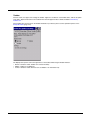
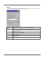
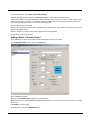
Connection
[
Avalanche
Server Address
Enter the IP Address or host name of the Mobile Device Server assigned to the mobile devicemobile
device.
Check Serial
Connection
Indicates whether the Enabler should first check for serial port connection to the Mobile Device Server before checking for a wireless connection to the Mobile Device Server.
Disable ActiveSync
Disable ActiveSync connection with the Mobile Device Server.
Restrict Adapt- Default is disabled. Minimum Link Speed dimmed. When enabled, the Enabler only allows a coner Link Speed nection to the server if the detected link speed is greater than or equal to the specified value.
2-7
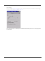
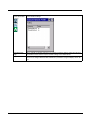
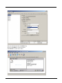
Server Contact
Note: Your screen display may not be exactly as shown above. Contact Technical Assistance (page 6-1) for upgrade
availability and version information.
Sync Clock
Contact
Reset the time on the mobile device based on the time on the Mobile Device Server
host PC.
• On Startup – Connect to the Mobile Device Server when the Enabler is accessed.
• On Resume – Connect to the Mobile Device Server when resuming from Suspend
mode.
• On IP Change – Connect to the Mobile Device Server when the IP address of the
mobile device changes.
• On Ext. Power – Initiate connection to the Mobile Device Server when the device
is connected to an external power source, such as based on a docking event.
Contact Periodically / Period- Allows the administrator to configure the Enabler to contact the Mobile Device Server
ic Update
and query for updates at a regular interval.
Wakeup device if suspended If the time interval for periodic contact with the Mobile Device Server occurs, a mobile
device that is in Suspend Mode can wakeup and process updates.
2-8
Reboot before attempt
Reboot mobile device before attempting to contact Mobile Device Server.
Require external power
Only connect when the mobile device has external power.
Use relative offset
Dimmed.
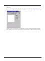
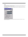
Data
The Data tab controls when data is transferred between the mobile device and the Mobile Device Server.
Real-time Statistics When checked, the statistics are transmitted over the network by the Enabler.
/ Network
Report
Specifies the Report Interval, how frequently the Enabler reports statistics to the Mobile Device
Server.
Retransmit After
Server Contact
Specifies if the device sends statistics to the Mobile Device Server immediately following a connection to the server.
Restrict Bandwidth When enabled, periodic updates from the Mobile Device Server are postponed until the mobile
to User Idle Time / device has been idle for the specified period of time. The default is disabled.
Transfer Data
When Device is
Idle
Idle timeout
Specify the length of time the device must be idle before a periodic update can run, used when
the parameter above is enabled.
2-9
Preferences
For best results, use AppLock to manage the taskbar. AppLock is resident on each mobile device, except HX3.
AppLock instructions are included in the relevant equipment User’s Guide available at www.honeywellaidc.com.
If the Preferences tab is not present on the Enabler installed on your device, please see the equivalent options on the
Startup/Shutdown (page 2-21).
Administration
By default, Keep settings unlocked for 10 minutes is disabled (checkbox is blank).
Application
Startup
Behavior of the Enabler when the mobile device boots up. The default is Monitor for Updates.
• Do not Monitor - When the device boots, do not launch the Enabler application and do not
attempt to connect to the Mobile Device Server.
• Monitor for Updates - Attempt to connect to the Mobile Device Server and process any updates
that are available. Do not launch the Enabler application.
• Launch User Interface - Attempt to connect to the Mobile Device Server and process any
updates that are available. Launch the Enabler application.
Shutdown
Behavior of the monitor when the Enabler is exited. The default is Monitor for Updates.
• Monitor for Updates - Attempt to connect to the Mobile Device Server and process any updates
that are available. Do not launch the Enabler application.
• Exit Application - Terminates the monitor (requires successful password entry if a password has
been configured).
Activity Log
Log
Level
2 - 10
Use this option to control the level of detail recorded in the log file. The default is No Activity Log.
• No Activity Log - No log file is written.
• Critical - Only critical errors written to the log files.
• Error - Communication or configuration problems are written to the log file along with critical
messages.
• Warning - Possible operation problems are written to the log file along with critical and error
messages.
• Info - Operational information is written to the log file.
• Debug - The most detailed log file.
Display
Level
Use this option to control the level of detail shown on the main Enabler screen. The default is Basic
Output.
• Basic Output - General information is displayed.
• Critical - Critical errors are displayed in addition to those above.
• Error - Communication or configuration problems are displayed in addition to those above.
• Warning - Possible operation problems are displayed in addition to those above.
• Info - Operational information is displayed in addition to those above.
• Debug - The most detailed list is displayed.
Display
Update Window Display
The user interface for the Enabler can be configured to dynamically change based on the status of the mobile
device connection with the Mobile Device Server.
At startup
Default is Half Screen. Options are Half screen, Hidden or Full screen.
On connect
Default is As Is. Options are As is, Half screen, or Full screen.
Normal
Default is As Is. Options are Half screen, Hidden or As Is.
2 - 11
Taskbar
For best results, use AppLock to manage the taskbar. AppLock is resident on each mobile device, with the exception
of the HX3. AppLock instructions are included in the relevant equipment User’s Guide available at www.honeywellaidc.com.
If the Taskbar tab is not present on the Enabler installed on your device, please see the equivalent options on the
Startup/Shutdown (page 2-21).
The Display State options control the appearance of the taskbar while using the Enabler interface.
• Normal - taskbar is visible, taskbar icons function normally.
• Hidden - taskbar is not displayed
• Locked - taskbar is visible, but most icons are hidden or for information only.
2 - 12
Execution
Note the dimmed options on this mobile device panel. This menu option is designed to manage downloaded applications for automatic execution upon startup.
Auto-Execute Selection
An application that has been installed with the Avalanche Management system can be run automatically following each boot.
Select
Auto-Execute
App
The drop-down box provides a list of applications that have been installed with the Avalanche
Management System.
Delay before execution
Time delay before launching Auto-Execute application.
2 - 13
Scan Config
For best results, use eXpress Config (page 4-1) and . eXpress Scan instructions are included in the relevant equipment User’s Guide available at www.honeywellaidc.com.
Scan Config functionality is a standard option of the Wavelink Avalanche MC system but is not currently supported on
the mobile device.
2 - 14
Shortcuts
For best results, use AppLock for this function. ppLock is resident on each mobile device, with the exception of the
HX3. AppLock instructions are included in the relevant equipment User’s Guide available at www.honeywellaidc.com.
Configure shortcuts to other applications on the mobile device. Shortcuts are viewed and activated in the Programs
panel. This limits the user’s access to certain applications when the Enabler is controlling the mobile device display.
2 - 15
SaaS
Use to configure the Enabler to connect with Avalanche on Demand. This is a Software-as-a-Service version of Avalanche. Using either of the SaaS configuration options below assumes the user has registered with Wavelink.
Disable SaaS
No SaaS connection is used.
Scan Configure
SaaS
Scan bar codes printed from within the Avalanche Console to configure the Enabler for the SaaS
connection.
Manually Config- Manually enter the SaaS connection information. Enter the server address on the Connection tab
ure SaaS
and the customer ID in the Company textbox.
2 - 16
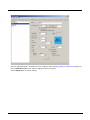
Adapters
Note: Review the network settings configuration utilities and the default values in the applicable mobile device user’s
guide before setting All Adapters to Enable in the Adapters applet.
Manage Network
Settings
When enabled, the Enabler will control the network settings. This parameter cannot be configured from the Avalanche Mobility Center Console and is enabled by default.
Manage Wireless
Settings
When enabled, the Enabler will control the wireless settings. This parameter cannot be configured from the Avalanche Mobility Center Console and is disabled by default. For Summit clients, Manage Wireless Settings should not be checked as configuration packages provide more
radio configuration options.
Current Adapter
Lists all network adapters currently installed on the mobile device. See VX6/VX7 Enabler
Installation (page 2-1) for VX6 and VX7.
Primary Adapter
Indicates if the Enabler is to attempt to configure the primary adapter (active only if there are
multiple network adapters).
Icon on taskbar
Places the Avalanche icon in the Avalanche taskbar that may, optionally, override the standard
Windows taskbar.
Use Avalanche Net- The Enabler will apply all network settings sent to it by the Mobile Device Server.
work Profile
2 - 17
2 - 18
Avalanche Icon
(varies by Enabler
version)
Selecting the Avalanche Icon will access the Avalanche Network Profile tab which will display
current network settings.
Use Manual Settings
When enabled, the Enabler will ignore any network or wireless settings coming from the Avalanche MC Console and use only the network settings on the mobile device.
Properties Icon
Selecting the Properties icon displays the Manual Settings Properties dialog applet. From here,
the user can configure Network, DNS and Wireless parameters using the displays shown below:
Note: A reboot may be required after enabling or disabling these options.
Network
DNS
Authentication
Wireless
Note: The Authentication tab may not be present in all versions of the Enabler.
For mobile device descriptions of these Enabler parameters, refer to the mobile device User’s Guide.
It is not recommend to enable “Manage Wireless Settings” for Summit Client devices.
Note: When you download a profile that is configured to manage network and wireless settings, the Enabler will not
apply the manage network and wireless settings to the adapter unless the global Manage wireless settings and
Manage network settings options are enabled on the Adapters (page 2-17) panel. Until these options are
enabled, the network and wireless settings are controlled by the third-party software associated with these
settings.
2 - 19
Status
The Status panel displays the current status of the mobile device network adapter selected in the drop down box. Note
the availability of the Windows standard Refresh button.
When the Windows Refresh button is tapped, the signal strength, signal quality and link speed are refreshed for the
currently selected adapter. It also searches for new adapters and may cause a slight delay to refresh the contents of
the drop-down menu.
Link speed indicates the speed at which the signal is being sent from the adapter to the mobile device. Speed is
dependent on signal strength.
2 - 20
Startup/Shutdown
For best results, use AppLock to manage the taskbar. ppLock is resident on each mobile device, with the exception of
the HX3. AppLock instructions are included in the relevant equipment User’s Guide available at www.honeywellaidc.com.
If the Startup/Shutdown tab is not present on the Enabler installed on your device, please see the equivalent options
on the Preferences (page 2-10) tab and the Taskbar (page 2-12) tab.
Do not monitor or launch Enabler When the device boots, do not launch the Enabler application and do not attempt
to connect to the Mobile Device Server.
Monitor for updates
Attempt to connect to the Mobile Device Server and process any updates that are
available. Do not launch the Enabler application.
Monitor and launch Enabler
Attempt to connect to the Mobile Device Server and process any updates that are
available. Launch the Enabler application.
Manage Taskbar (Lock or Hide)
Note the dimmed options. The Enabler can restrict user access to other applications when the user interface is accessed by either locking or hiding the taskbar.
Program Shutdown (Continue or
Stop monitoring)
The system administrator can control whether the Enabler continues to monitor
the Mobile Device Server for updates once the Enabler application is exited.
2 - 21
Exit
The Exit option is password protected. The default password is leave. The password is not case-sensitive.
Depending on the behavior chosen for the Shutdown parameter, the following screen may be displayed:
Note: The icon on the screen above may differ based on the version of the Enabler installed on the mobile device.
Change the option if desired. Tap the X button to cancel Exit. Tap the OK button to exit the Avalanche applet.
Using Remote Management
1. Configure the radio to connect to the network running the Mobile Device Server. After the mobile device is connected, proceed to step 2.
2. If it is desired to configure the radio using the Summit package, add the configured package to the Wavelink Avalanche MC
Console and enable it.
3. Verify RMU.CE.CAB exists in the \System\RMU folder.
4. Double click the mobile device enabler CAB file in the \System folder.
5. The enabler automatically launches after installation and contacts the Mobile Device Server. The Avalanche MC Console
connected to that Mobile Device Server identifies the remote device and performs a sync. This downloads any available
packages available for the mobile device.
2 - 22
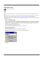
Using eXpress Scan
eXpress Scan Desktop Icon
If the mobile device has an eXpress Scan icon on the desktop, eXpress Scan may be used for the initial configuration of the
device.
If the eXpress Scan icon is not present on the desktop, see Installing the Enabler on Mobile Devices (page 2-1). If the icon is
still not present, the Enabler must be updated. Contact Technical Assistance (page 6-1) for upgrade information.
If the eXpress Scan icon is present, follow these steps to configure the mobile device to connect with the wireless network and
the Mobile Device Server.
Step 1: Create Bar Codes
Bar codes are created with the eXpress Config utility on the desktop/laptop computer, not the mobile device. Depending on
the bar code length and the number of parameters selected, eXpress Config generates one or more bar codes for device
configuration. The bar codes contain configuration parameters for the wireless client in the mobile device and may also
specify the address of the Mobile Device Server.
Bar codes should be printed at a minimum of 600 dpi.
Please see Creating Configuration Bar Codes with eXpress Config (page 4-9)
Step 2: Scan Bar Codes
For each mobile device to be configured, please follow these instructions.
Start eXpress Scan on the mobile device by double-tapping the eXpress Scan icon.
Enter the bar code password, if any.
Click Start.
2 - 23
Bar code 1 must be scanned first. The scanned data is displayed in the “Data” text box. The password, if any, entered
above is compared to the password entered when the bar codes were created.
If the passwords match, the bar code data is processed and the screen is updated to reflect the number of bar codes
included in the set.
If the passwords do not match, an error message is displayed. The current screen can be closed using the X box in the
upper right corner. The password can be re-entered and Bar Code 1 scanned again.
The remaining bar codes may be scanned in any order. After a bar code is scanned, that bar code is removed from the
Remaining: list and placed in the Scanned: list.
Step 3: Process Completion
After the last bar code is scanned, the settings are automatically applied.
Once configured, the mobile device is warmbooted. Once connected to the wireless network and the Mobile Device
Server, any software updates and additional configuration data are downloaded.
2 - 24
3
Avalanche Mobility Center Console
Introduction
This section provides an overview of the Avalanche MC Console when it is being used to manage Honeywell mobile devices on
a network. Online help (an Internet connection is required to access online help) is available using the Help option in the Console Main Menu.
The Avalanche Mobility Center Console does not communicate directly with the managed devices. Instead, the Mobility Center
Console communicates with the Mobile Device Server and the Mobile Device Server communicates with the monitored devices.
•
•
•
•
Avalanche Mobility Center Console and the Avalanche Mobile Device Server run on a desktop PC.
Avalanche Enabler runs on the monitored device, see Supported Devices (page 1-3).
The Enabler communicates with the Mobile Device Server.
Avalanche Remote Control is an optional plug-in for Avalanche Mobility Center. Remote Control includes both a console
portion and a software package to be downloaded to the monitored devices.
For detailed and technical information for the Avalanche Mobility Center Console running on a desktop PC, refer to the Wavelink’s Avalanche Mobility Center documentation. This document is available for download from the Wavelink website,
www.wavelink.com. It is not included in this guide.
Note: Screenshots in this section are taken from the Avalanche Mobility Center Console Version 4.2.
Installation
Minimum requirements for the Avalanche Mobility Center server installation (when managing 1000 devices or less) are:
• Microsoft Windows 2000 Professional (SP4), Windows Server 2000 (SP4), Windows Server 2003 (SP1 or later) or Microsoft
Windows XP (SP2 or later) operating system.
• Intel Pentium 4 Processor at 2.8GHz (or equivalent)
• 2 GB free disk space (plus an additional 5 MB for Avalanche Remote Control if desired)
The optimal requirements for the Avalanche MC server depend on a number of factors, such as the number of Servers and
devices you want to manage and your overall network setup. Please refer to the Wavelink Avalanche Mobility Center User’s
Guide, available on www.wavelink.com for more details. For more information on Avalanche Remote Control, refer to Avalanche
Remote Control (page 5-1) and Wavelink’s Avalanche Remote Control documentation available at www.wavelink.com.
Reminder: When the Mobile Device Server sends an update to a mobile device Enabler, the Enabler acknowledges receipt
back to the Mobile Device Server.
Avalanche Mobility Center Console Components
There are many components to the Avalanche Mobility Center Console. This section covers the areas specific to the Honeywell
mobile devices and their interaction with the Avalanche MC Console. For complete details on general Avalanche MC operation,
please see Wavelink’s Avalanche Mobility Center documentation, available on www.wavelink.com.
Specific items in this section include:
• Software Profiles
• Network Profiles
• Mobile Device Inventory and Mobile Device Groups
• Mobile Device Details
This section assumes:
• The user has set up the mobile devices to connect to the network and they meet the minimum software load requirements
mentioned elsewhere in this manual.
• The user has installed Avalanche MC and set up a Mobile Device Server as described in the Avalanche Mobility Center User’s
Guide.
The Avalanche MC Console Navigation menu appears as shown below. In this example, a dServer location named MydServer
has been created.
3-1
Software Profiles
A Software Profile contains one or more Software Packages (.AVA files). To create an .AVA file from a software module, please
see Creating a Software Package with eXpress Config (page 4-2).
Click on Software Profiles in the Avalanche MC Console Navigation pane.
The Software Profile List is displayed in the upper right hand portion of the screen.
Use the Add Profile button to create a new Software Profile.
When prompted, enter a name for the profile as desired. In the example above, the Software Profile is named RFTerm test.
After the profile has been created, information on the profile is displayed including the Name, Status (Disabled or Enabled) and
Selection Criteria.
To add a Software Package to the profile, make sure the desired Software Profile is highlighted and click on the Software
Packages tab, below.
3-2
Several options are available.
The Install button allows the user to browse to and select a Software Package. Browse to the location where the .AVA files created with eXpress Config are located. Once a package is selected, it appears in the list.
The Configure button launches eXpress Config when a supported software package is selected. For more details on these
features and the available options for each type of software, please refer to Configuring a Software Package with eXpress
Config (page 4-4).
Additionally, if a software package contains Summit radio software, the Configure button offers the user a choice of configuration
options:
• eXpress Config – Config: Use this option to configure a software package to be downloaded to the device via the connection
to a Mobile Device Server.
• eXpress Config – Barcodes: Use this option to create bar codes containing the radio configuration parameters and Mobile
Device Server address. These bar codes can be scanned by the mobile computer. The configuration data contained in the
bar codes allows the device to connect to the network and Mobile Device Server for additional software and configuration
parameters.
The Enable / Disable button allows the user to enable or disable this Software Package for download as part of the Software
Profile.
Information on the Software Package includes the Name, Status (Disabled or Enabled), Type, etc. All Honeywell packages are
Auto Run. This package type automatically executes following a successful download to the mobile device. It does not modify
the Application (or Programs) menu in the mobile device.
When finished, click on the General Settings tab and enable the Software Profile.
Click on the Save icon in the toolbar to save changes to the Software Profile.
Next, select My Enterprise > MydServer (substitute the name of your dServer location). Click on the Software Profiles tab in
the lower part of the screen. Add the Software Profile created above.
Click on Tools > Deploy Now using the toolbar at the top of the screen.
The Software Profile is ready to be downloaded:
• Automatically at the next reboot of the mobile device
• Manually by selecting the device from the Mobile Device Inventory list and clicking Update Now.
• At a scheduled time
Network Profiles
Click on Network Profiles in the Avalanche MC Console Navigation pane.
The Network Profile List is displayed in the upper right hand portion of the screen.
3-3
Use the Add Profile button to create a new Network Profile. When prompted, enter a name for the profile as desired. In
the example above, the Network Profile is named test. After the profile has been created, information about the profile is
displayed including the Name, SSID, Security, Status (Disabled or Enabled) and Selection Criteria.
Wireless and network parameters are set as part of a Network Profile. To enable management of these settings, make sure
the desired Network Profile is highlighted and click on the General Settings tab.
Click the Manage Network Settings checkbox to allow Avalanche MC to manage network settings on the mobile devices
as part of this network profile.
Click the Manage Wireless Settings checkbox to allow Avalanche MC to manage wireless settings on the mobile device
as part of this network profile.
Set Network and Wireless settings as described in the following sections.
Click on the Save icon in the toolbar to save changes to the Network Profile.
When finished, click on the General Settings tab and enable the Network Profile.
Next, select My Enterprise > MydServer (substitute the name of your dServer location).
Click on the Network Profiles tab in the lower part of the screen. Add the Software Profile created above.
Click on Tools > Deploy Now using the toolbar at the top of the screen.
The Network Profile is ready to be downloaded:
• Automatically at the next reboot of the mobile device
• Manually by selecting the device from the Mobile Device Inventory list and clicking Update Now.
• At a scheduled time
Network Settings
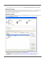
When a Network Profile is selected, click on the Network Settings tab to see available parameters.
3-4
The network settings include:
• Server Address – When checked, this option allows the mobile device to be linked to a specific Mobile Device
Server. When not used, the device links to the first Mobile Device Server that responds to the broadcast.
• Gateway – The router address. To use the router address of the current Mobile Device Server, enable the Use
Mobile Device Server Setting checkbox.
• Subnet Mask – The subnet mask in IP address format. To use the subnet mask of the current Mobile Device Server,
enable the Use Mobile Device Server Setting checkbox.
• Default DNS Domain – The default DNS domain.
• Primary DNS – The IP address of the primary DNS.
• Secondary DNS – The IP address of the secondary DNS.
• Tertiary DNS – The IP address of the tertiary (third in line) DNS.
• IP Address Assignment – Provides options for assigning an IP Address:
• Manual Assignment – No IP address is assigned by Avalanche MC. IP address must be set on the device. Review
the Wireless Network Configuration chapter in the appropriate equipment-specific User’s Guide.
• Avalanche Pool – Avalanche allows a range of IP addresses to be specified. If this option is used, an IP address
is assigned from that range.
• DHCP – A DHCP server is contacted for an IP address.
When finished, complete the process as detailed in Network Profiles (page 3-3).
Mobile Device Inventory
When a mobile device running an Enabler contacts the Mobile Device Server, the mobile device is added to the Mobile
Device Inventory.
To view the Mobile Device Inventory, select My Enterprise > MydServer (substitute the name of your dServer location)
> Mobile Device Server. Click on the Mobile Device Inventory tab.
Each mobile device includes identifying information such as model name, IP address and MAC address. Additional
information includes the status and time or date of last contact.
A check mark indicates a device is up to date, an X indicates a device is not up to date.
3-5
For more information on the Status icons, please refer to the Wavelink Avalanche Mobility Center User’s Guide.
Mobile Device Groups
It may be desirable to create Mobile Device Groups when managing a large number of devices. To create a Mobile Device
Group, right click on Mobile Device Group in the Navigation pane. Select New and assign a name to the group.
Complete the entries as desired for the group.
Mobile Device Details
Anytime a device is listed in the Mobile Device Inventory or the Mobile Device Group screen, details on the device may be
displayed by double clicking on the device.
Of particular interest for the Honeywell mobile devices are the RMU properties:
• FreeSpaceAvailable – For more information please see Space Requirements on Mobile Computers (page 4-1).
• StorageRAM – For more information please see Preparing a Device for Remote Management (page 2-3).
3-6
4
eXpress Config
Introduction
eXpress Config is installed on a desktop/laptop computer with a Windows XP operating system. It is an accessory product to
the Wavelink Avalanche MC system management application. The desktop/laptop computer running the Wavelink Avalanche
MC system management application is, for the purposes of this document, described as the Avalanche MC Console.
Software Packages distributed to the Mobile Device Servers and Enablers do not include the eXpress Config application.
eXpress Config provides three basic functions:
• eXpress Config can be used to create software packages for Honeywell software. See Creating a Software Package with
eXpress Config (page 4-2).
• eXpress Config can be used to configure the software packages, either when the package is created or after the package has
been imported into the Avalanche MC console. See Configuring a Software Package with eXpress Config (page 4-4).
• eXpress Config can be used to generate and print bar codes to be used with the eXpress Scan feature installed on certain
Honeywell devices. The bar codes generated using eXpress Scan are designed for the initial wireless network and Mobile
Device Server configuration on the mobile device. See Creating Configuration Bar Codes with eXpress Config (page 4-9).
The assumption is made that the user has a basic familiarity with Microsoft Windows terms, basic Windows components and
their use/function. For example, assumption is made that the user is familiar with the operation of Windows Title Bars, Menu
Bars, Navigation Trees, Configuration Panels, and Message Panels. The final assumption is that the user has access to standard Windows Help vehicles: on-line Help, Windows Help documents, etc. available from Microsoft and on-line help or documentation available from Wavelink.
Avalanche Software Collections
Software collections are made up of one or more Software Packages. Software Packages are created using eXpress Config. Software Packages created using eXpress Config include a software module and parameter configuration information.
Honeywell software modules compatible with eXpress Config include a data definition file (.DDF) which communicates the
configurable parameters for that particular software module to eXpress Config. The DDF file was not included in earlier
Avalanche software packages.
The Wavelink Package Builder can be used to send non-Honeywell supported software, if desired.
A network administrator interacts with the Avalanche Console to define policies and create software collections that are distributed through the Avalanche Mobile Device Servers to the Avalanche Enablers running on client devices.
When a Software Package is installed into the Avalanche MC Console, it becomes available for inclusion in a Software Collection. eXpress Config is launched by clicking the Configure tab, after selecting a Software Package that has been
installed in the Avalanche Console and included in a Software Collection. eXpress Config reads the data definition file
which is included in the software package and presents the configurable parameters for that Software Package to the
device administrator through a graphical user interface.
Once the device administrator has updated the configurable parameters, the new parameter values are included in the
Software Package.
The device administrator also defines policies that are assigned to each Software Collection. These policies determine
which client device receives the software collection.
Note: Honeywell software modules include operating system modules, an RFTerm module, an AppLock module, a bar code
wedge module or a radio module. Software modules are sometimes also referred to as “G-numbers” or “P-numbers”.
The type of software modules available vary depending on the operating system of the managed device
Space Requirements on Mobile Computers
There must be sufficient space on the mobile device when downloading software collections.
• The mobile device must have a minimum of 128MB CF card.
• The free space on the CF card must be at least twice the size of the largest file in the package.
• The RMU creates a real-time property called RMU.FreeSpaceAvailable which can be read from the Avalanche MC
Console. To view this property, right-click on a device in the Avalanche MC Console and click Mobile Device Settings….
Select the Properties tab. The RMU.FreeSpaceAvailable property is included in the list of properties only after the RMU
has executed at least one time on the remote device and the Enabler has successfully synchronized with the Avalanche
MC Console.
4-1
Installation
The installer program places eXpress Config on a desktop/laptop computer running Windows XP. The computer requires the
.NET Framework Version 2.0 be available before the software package can complete the installation.
Prerequisites
• .NET Framework installer from Microsoft downloaded and installed on the Avalanche Console device.
Note: The installation program verifies that .NET Framework Version 2.0 is installed. If the .NET framework is not installed,
the eXpress Config software does not install.
Install eXpress Config
1. Double-click the eXpressConfigSetup Wizard link. The Wizard screen opens. The installer will guide you through the
steps required to install eXpress Config on your computer.
2. Click Next to continue. Click Cancel at any time to abort the installation and exit.
3. Select the Installation folder. The default Installation folder is either
• For 32-bit computers: \Program Files\Honeywell\eXpress Config (version) e.g.: eXpress Config 1Bb, or
• For 64-bit computers: \Program Files (x86)\Honeywell\eXpress Config (version) e.g.: eXpress Config 1Bb.
4. If needed, browse to a different folder location or enter the path and name for the preferred folder.
5. Select (the current version of the) eXpress Config user access permission. The default is Everyone.
6. Click Back to return to the previous display or Next to continue. Click Cancel at any time to abort the installation and
exit.
7. Click Next to start the installation.
8. During installation a shortcut to eXpress Config is created on the desktop. A shortcut is placed in the Start Menu under
Programs>Honeywell.
9. Click Back to return to the previous display. Click Cancel to abort the installation and exit.
10. Click Close to exit the installation utility when the installation is complete.
11. Double-click the eXpress Config icon on the desktop or in Start > Programs > Honeywell to launch eXpress Config.
The eXpress Config Package Selection screen is displayed.
Please see sections titled Creating a Software Package with eXpress Config (page 4-2) and Configuring a Software
Package with eXpress Config (page 4-4) for explanations of the screen display objects that may be presented to the user.
Uninstall eXpress Config
Start > Control Panel > Add or Remove Programs
Depending on the version installed, select either eXpress Config version or Package Builder version e.g. Package Builder
0Ab, 1Ab, etc., in the Currently Installed Programs list to uninstall eXpress Config.
Click the Change/Remove button.
Select Remove and follow the prompts on the screen.
The eXpress Config program is removed from the desktop/laptop computer. The .NET Framework is not removed.
Creating a Software Package with eXpress Config
eXpress Config Icon on PC or Laptop Desktop
Prerequisites:
• Honeywell software module package, per device type.
4-2
• A decision on whether to include configuration data only. See Package Selection Screen (page 4-3).
When including an operating system package, it is important to also include a radio package so that after the reboot the radio can automatically associate. If the radio package is not sent, the device loses connection to the
network and manual configuration of the radio parameters is required.
• Remote Management Utility (RMU) (page 1-2) that includes eXpress Scan is installed on the target device. Devices
manufactured after October 2007 already include this updated RMU as part of the system load. Installation of the RMU
is detailed in Preparing a Device for Remote Management (page 2-3).
Process Overview
1. Download the software module from Honeywell.
2. Run eXpress Config by double-clicking the eXpress Config icon on the desktop or in Start > Programs > Honeywell.
3. Browse to the location of the downloaded software.
4. Specify a destination to store the package that is created.
5. If desired, click the Configure Package button to configure the parameters. Otherwise, the default values are used.
a. To send parameters only (no software is to be installed) check the Include Configuration Only checkbox.
b. Review parameters in the Navigation Tree (page 4-5).
c. Left click a parameter to expand the element. See Controls (page 4-6).
d. Left click a sub-element. See Controls (page 4-6).
e. Edit the parameter values in the Configuration Panel. See Configuration Panel (page 4-7).
f. Save changes and exit. See Menu Bar (page 4-5).
7. Click OK to create the package. Depending on the options selected, the package includes configuration parameters,
software or both parameters and software.
8. Using an Avalanche Mobile Device Server with the package installed, download the package to the target mobile
device enabled. See User Interface (page 2-4).
9. Verify the Remote Management Utility is installed on the target device. See Preparing a Device for Remote
Management (page 2-3).
Important Note for Software Packages Containing an Operating System
If the software package contains an Operating System (OS) module, the OS in the software package must be the same
type as the OS currently installed on the mobile device.
• If the mobile device is using CE 4.2, then the OS in the package must also be CE 4.2. Avalanche cannot be used to
upgrade a mobile device from CE 4.2 to CE 5.0 or to downgrade a device from CE 5.0 to CE 4.2.
• Avalanche cannot be used to replace a standard (no Java) OS with an OS containing Java or to replace an OS containing
Java with a standard OS.
• Avalanche cannot be used to change the OS font installed on the device. Both the device and OS module to be
downloaded must have the same font (English, Korean, Japanese, etc.).
If the radio is to be managed remotely, it is important to include the radio package in this group so that after the
reboot the radio can automatically associate. If the radio package is not sent, the device loses connection to the
network and manual configuration of the radio parameters is required.
Package Selection Screen
The eXpress Config Package Selection screen is displayed:
4-3
The user may create directories as desired for the G-Number and Destination locations. Create these directories before
using eXpress Config.
Browse to the folder location of the source software module file and select the desired file for the package that will be created. If the package can be configured for multiple devices, eXpress Config displays a list of available devices. Select the
appropriate device and press the Accept button to proceed.
Browse to the folder for the destination location. The destination folder contains the package after it is built.
The Configure Barcodes… button is only present when the software package contains Summit radio software. Use the
Configure Barcodes… button to create configuration bar codes to be used for the initial configuration of a mobile device.
See Creating Configuration Bar Codes with eXpress Config (page 4-9) for details on this feature.
Use the Configure Package… button to create a custom configuration for the package being built. The configuration
parameters are applied to the package file when the OK button is clicked. If Cancel is selected, the configuration is lost.
The Configure Package button is disabled if there is no .DDF file in the software module directory.
Enable the Include Configuration Only checkbox when you want to include configuration data only. The software module
is not included in the package created when this control is checked.
Click OK to create the package file in the specified folder or Cancel to abort the operation and close the program.
Updating Many Devices With The Same Configuration
1. Update a single mobile device with the new configuration and verify all functions perform as expected on the target
device.
2. If all functions do not perform as expected, make changes to the configuration, if necessary, and update a single
mobile device. Verify all functions perform as expected.
3. Proceed to update all mobile devices with the verified configuration.
Procedure for Removing Package Files on the Remote Device
1. Right-click on a monitored device in the Wavelink Avalanche MC Console and select Client Settings.
2. Check Delete Orphaned Packages checkbox.
3. Click the Update Now button.
4. The next time the RMU runs, it will remove the packages from the device.
Note: Operating System packages and the RMU itself can only be removed from the monitored device manually.
Configuring a Software Package with eXpress Config
eXpress Config provides a configuration interface for the software provided in each Software Module Package. When one of
these packages is opened in the Avalanche MC Console, it is eXpress Config which is launched. eXpress Config presents a
user interface for providing configuration data for the software module also bundled in that package – and only that software.
For example, if a Package contains the RFTerm module, eXpress Config, when launched from that package, presents only configuration parameters relevant to RFTerm.
4-4
Only Honeywell software modules that include a Package file (PKG) and Data Definition File (DDF) can be configured with
eXpress Config. Since Data Definition Files are a requirement for this software, that means software modules released prior to
the release of eXpress Config are not configurable using eXpress Config.
When a package is “opened” – that is, eXpress Config is launched – eXpress Config displays all configuration parameters
described in the Data Definition File (and a REG file if included). The first time a package is configured, default values for all
parameters are presented. Changes to the parameters are saved back to the package. Every subsequent time the package is
configured, the last saved configuration data is presented. All parameter changes are saved to the package, but only ‘marked’
data is sent to the remote device. Parameter values modified by the user are automatically marked. The user may change the
‘marked’ status of any parameter or group of parameters. eXpress Config can also be opened from the Avalanche MC Console,
and in this case marked data values are sent to the devices and are saved to the package within the Avalanche MC Console.
Launch eXpress Config through the Avalanche MC Console by right clicking on the software module package name and select
Configure Package on the right click menu. Then select eXpress Config from the Configure Package menu.
There may be two eXpress Config entries, depending on the currently selected software package.
• eXpress Config – Config is present for all software packages and is the option covered in this section.
• Additionally, eXpress Config – Barcodes is present for some Summit radio software packages. Please see Creating
Configuration Bar Codes with eXpress Config (page 4-9) for details on this process.
Menu Bar
Alt key shortcuts are available for the Menu Bar. For example, pressing the <Alt><F> key combination will cause the ‘File’
menu bar drop-down to be displayed. When a drop-down menu is displayed, pressing the key corresponding to the underlined letter in any menu item causes that menu item to be invoked.
The Menu Bar contains two menu items: File and Edit.
File Menu
Save
Causes the current configuration parameters to be written to the embedded ‘ini’ file. This includes all parameters for the active software package, not just visible parameters. There are no additional user interface elements displayed when ‘Save’ is selected. A Save confirmation dialog box is presented to the user. Buttons
on the Save dialog have the following functions:
• Yes – Causes configuration changes to be saved to the software package, and the configuration utility to
close.
• No – Causes the configuration utility to close without saving unsaved changes.
• Cancel – Causes the configuration dialog to close, but leaves the configuration utility open. User control
stays with the configuration utility. Unsaved configuration changes are not saved.
About
Displays a dialog containing the version number of the configuration utility and a copyright notice. Click the
OK button or the X to close the dialog box and return to the configuration utility.
Exit
The function of the Exit option is to exit the configuration function:
• If eXpress Config was accessed from the Avalanche MC Console, selecting Exit returns you to
Avalanche.
• If the Configure Package button was clicked on the Package Selection screen, selecting Exit returns you
to the Package Selection screen.
Edit Menu
The Edit menu bar drop-down contains three items: Cut, Copy and Paste. These three items have the standard Windows functionality of cutting, copying and pasting selected text in user editable fields.
Navigation Tree
A navigation tree may have multiple root nodes. The organization of the navigation tree mirrors the navigation of the program being configured.
4-5
Controls
At the left most position in each entry is a control to expand or contract the subordinate tree elements. The control can
be toggled from [ + ] to [ - ] with a left mouse click.
Next is a check box that indicates if parameters in that branch of the tree are selected for inclusion in the software
package.
The check box has three states:
Checked
This state indicates that all parameters in the tree branch are selected for inclusion in the software
package.
Unchecked
(Blank) This state indicates that none of the parameters in the tree branch are selected for inclusion in
the software package.
Mixed
(Dimmed checkmark) This state indicates that some parameters in the tree branch are selected for inclusion in the software package and some parameters are not included.
Left click a leaf in the expanded branch to display the parameters associated with the leaf to be displayed in the Configuration panel.
Right click a label or associated check box to display a Selection panel. The selection panel contains three choices:
Select All
Causes the check box to transition to the Checked state. The parameters will be included in the software package.
Unselect All
Causes the check box to transition to the Unchecked state. The parameters will not be included in the
software package.
Reset To
Defaults
Causes default values to be applied to all parameters in that branch and sub-branches. Default parameters will be included in the software package.
Each check box transition is propagated both upward and downward through the navigation tree, and to the individual
parameters in the configuration panel.
Root Nodes
Reboot Options
Indicates whether the client device is to be rebooted when the new package is installed. Rebooting the client after
installing the package is the surest way to cause new parameters and software to be applied immediately. However, rebooting the device may disrupt any end-user operations in progress.
Default
Options
Prompt
Auto - Causes the device to automatically reboot (user is not prompted).
Prompt - Causes the Enabler to display a prompt asking if the device is to be rebooted immediately,
or if the reboot should be delayed. ‘Prompt’ is the default value.
If no reboot is desired, do not include the reboot options parameter in the package.
Data File Options
The element label is derived from the specific application configuration menu.
4-6
There is always a root node named after the data file (without the file extension), for example ‘rfterm’. Packages
that require a reboot for configuration changes to become effective include a Reboot Options node at the root level
(see above).
The branches or leaves on the navigation tree lead to user-configurable parameters. See Configuration
Panel (page 4-7) for instruction.
Configuration Panel
The Configuration Panel is designed to allow the device administrator to view, add, edit and delete device-specific or application-specific configuration data.
Parameters and elements displayed in the Configuration Panel are the same as those displayed on the mobile device. Only
parameters and elements with an editable attribute set to True are available for edit. If a parameter or element is dimmed,
it cannot be edited. There are visual and navigation modifications due to differences between the application environment
(Windows CE or Windows Mobile) and the Configuration Panel environment (assumed to be Windows XP), and because of
differences in navigation between the target application and the configuration utility.
The lower portion of the screen contains details on the selected parameter which may include the default value for the
parameter, parameter descriptions, etc.
Controls
When a Control is selected, the Control’s context-sensitive help text is displayed in the Message Panel.
Scroll Bar
Use the up/down scroll bar to view elements listed in the configuration panel
Drop Down Bar
Click the down arrow to view all possible element values. Highlight and click the desired value.
Text/Number Edit
Move the cursor to the data entry field and type the desired value.
Toggle
Click the button to switch between the named states e.g,. Yes/No, On/Off, etc.
Review all parameters before saving the file.
4-7
Component Parameters
Note: Available parameters may vary by software version.
Software Component
Configurable Parameters
Operating Systems
Only parameters associated with the following control panel applets. (Applets may
have different names or parameters than these listed below.)
Scanner (Data Collection Wedge or Barcode Wedge)
• Display (backlight and blanking)
• Power
All parameters in each of these applets are configurable. In general, this means that,
in addition to the Wedge configuration, power management, display backlight and display blanking are configurable.
See the device specific User’s Guide.
Equipment Specific Notes:
• Note that some Battery panels may include some reporting and diagnostic
capabilities. These diagnostic and reporting capabilities are not implemented
through eXpress Config.
RFTerm
All parameters except:
Keybars
• Bar code stripping (note that similar functionality is supported in the Data Collection
Wedge and Scanner Wedge)
• Windows Printer config (note that the Windows Printer config is also not included in
the OS configuration.)
• Font color
See the RFTerm User’s Guide for a full list of parameters for the target device.
AppLock
All parameters. See the device specific User’s Guide.
Scanner (Bar Code Wedge)
or Data Collection
(DC Wedge)
All parameters. See the device specific User’s Guide.
Scanner Prefix and Suffix Note:
• Note that the Prefix and Suffix entry field accepts up to 76 characters to allow a
combination of normal, hat encoded and hex characters. However, the Suffix and
Prefix are each limited to 19 logical characters after parsing. If the string entered
results in more than 19 logical characters, the string is truncated to 19 characters.
No warning or error message is provided if the result is truncated.
Enabler
None.
Summit Client
The following Summit wireless parameters are included:
•
•
•
•
•
•
•
•
•
•
•
•
•
•
Active Profile
Profile Name
SSID
Client Name
Power Save
TX Power
Bit Rate
Radio Mode
Authentication Type
EAP Type
Encryption
User Name
User Password
CA Filename
•
•
•
•
•
•
•
•
•
•
•
•
•
•
RX Diversity
WEP Key 1-4
Transmit Key
PSK
TX Diversity
Roam Trigger
Roam Delta
Roam Period
Ping Payload
Ping Timeout
Ping Delay
LED
Hide Password
Admin Override
•
•
•
•
•
•
•
•
•
•
•
•
•
•
Auth Server
Admin Password
Frag Threshold
Certs Path
CCX Features
WMM
TTLS Inner Method
PNK Caching
BG Channel Set
DFS Channels
DFS Scan Time
Ad Hoc Channel
Tray Icon
Auth Timeout
Additionally:
• The RMU can be used to install user certificates into the certificate store on the
mobile device. The certificate must already be on the device.
• User credentials can be created and remotely managed using eXpress Config.
See the device specific user’s Guide for details on the Summit parameters.
4-8
Creating Configuration Bar Codes with eXpress Config
When a software package contains Summit radio software, eXpress Config can be used to create bar codes to configure the
basic parameters that allow a mobile device to connect with the wireless network and the Mobile Device Server. The configuration screens appear similar to those for any other Honeywell software package, as described in the previous section, but with
some notable differences:
• The Configure Barcodes… button is only present when the software package is for Summit radio software. The Configure
Barcodes… button is not present for Summit software revisions released prior to the eXpress Scan feature.
• This option only provides configuration data. No software is downloaded to the mobile device. However, once the
configuration bar codes are used to configure the mobile device to contact the wireless network and Mobile Device Server,
software upgrades can then be performed.
• When Configure Barcodes… is selected, the parameters available for configuration differ from the parameters available
when Configure Package… is selected.
• The Menu bar includes a Barcode > Print option.
Launch eXpress Config through the Avalanche MC Console by right clicking on the software module package name and
select Configure Package on the right click menu. Then select eXpress Config – Barcodes from the Configure Package
menu.
If eXpress Config – Barcodes is not present, one or more of the following applies:
• The software package is not a Summit radio package.
• The Summit radio package does not meet the minimum revision requirements.
• eXpress Config does not meet the minimum revision requirements.
Note: Contact Technical Assistance (page 6-1) for upgrade availability and minimum revision requirements.
There may be two eXpress Config entries, depending on the currently selected software package.
• eXpress Config – Barcodes is present for some Summit radio software packages and is the option covered in this section.
• eXpress Config – Config is present for all software packages and is the option covered in Configuring a Software Package
with eXpress Config (page 4-4).
It is not necessary to save the configuration parameters before printing the bar codes.
If Save is selected, the saved parameters become part of the software package and are sent if the software package is
deployed in the Avalanche MC Console. If Save is not selected, the bar codes can be printed, but the software package, if
deployed, does not contain the configuration data included in the bar codes.
Process Overview
Prerequisite: Remote Management Utility (RMU) (page 1-2) that includes eXpress Scan is installed on the target device.
Devices manufactured after October 2007 already include this updated RMU as part of the system load. Installation of the
RMU is detailed in Preparing a Mobile Device for Remote Management.
1. Download the software module from Honeywell.
2. Run eXpress Config by double-clicking the eXpress Config icon on the desktop or in Start > Programs > Honeywell.
3. Browse to the location of the software for the Summit radio.
4. Specify a destination to store the package that is created.
5. Click the Configure Barcodes button to configure the parameters.
a. Review parameters in the Navigation Tree (page 4-11).
b. Left click a parameter to expand the element. See Controls (page 4-12).
c. Left click a sub-element. See Controls (page 4-12).
d. Edit the parameter values in the Configuration Panel (page 4-12).
e. Save changes. See Menu Bar (page 4-10).
f. Print the bar codes and exit. See Menu Bar (page 4-10).
6. On a mobile device with eXpress Scan installed (as part of the Enabler installation), click on the eXpress Scan icon.
7. Enter the password, if any, used when the bar codes were created.
4-9
8. Scan Barcode 1 first. The password, if any, is verified against the password used when the bar code was created.
After the first bar code is scanned, the remaining bar codes may be scanned in any order.
9. After the final bar code is scanned, the settings are applied to the mobile device and it automatically reboots.
10. After it reboots and connects to the Mobile Device Server, any additional configuration parameters and software
packages are downloaded to the mobile device.
Menu Bar
Alt key shortcuts are available for the Menu Bar. For example, pressing the <Alt><F> key combination will cause the ‘File’
menu bar drop-down to be displayed. When a drop-down menu is displayed, pressing the key corresponding to the underlined letter in any menu item causes that menu item to be invoked.
The Menu Bar contains three menu items: File, Edit and Barcodes.
File Menu
Save
Causes the current configuration parameters to be written to the embedded ‘ini’ file. This includes all parameters for the active software package, not just visible parameters. There are no additional user interface elements displayed when ‘Save’ is selected. A Save confirmation dialog box is presented to the user. Buttons
on the Save dialog have the following functions:
• Yes – Causes configuration changes to be saved to the software package, and the configuration utility to
close.
• No – Causes the configuration utility to close without saving unsaved changes.
• Cancel – Causes the configuration dialog to close, but leaves the configuration utility open. User control
stays with the configuration utility. Unsaved configuration changes are not saved.
About
Displays a dialog containing the version number of the configuration utility and a copyright notice. Click the
OK button or the X to close the dialog box and return to the configuration utility.
Exit
The function of the Exit option is to exit the configuration function:
• If eXpress Config was accessed from the Avalanche MC Console, selecting Exit returns you to
Avalanche.
• If the Configure Package button was clicked on the Package Selection screen, selecting Exit returns you
to the Package Selection screen.
Edit Menu
The Edit menu bar drop-down contains three items: Cut, Copy and Paste. These three items have the standard Windows functionality of cutting, copying and pasting selected text in user editable fields.
Barcodes Menu
The Barcode menu contains one item, Print…. When selected, a standard Windows print dialog box is displayed,
allowing for selection of a printer, pages to be printed and the number of copies.
4 - 10
Bar codes should be printed at a minimum of 600 dpi. Additional printer properties can be accessed by clicking the
Properties or Preferences button. Click the ? button for built in Windows help on the printer or printer properties/preferences.
The above bar codes are provided for reference only and should not be used for device configuration. The actual bar
codes generated depend on the configuration parameters selected and the values entered for those parameters.
Navigation Tree
The navigation tree has limited nodes when Configure Barcodes… has been selected.
4 - 11
Controls
At the left most position in each entry is a control to expand or contract the subordinate tree elements. The control can
be toggled from [ + ] to [ - ] with a left mouse click.
Next is a check box that indicates if parameters in that branch of the tree are selected for inclusion in the software
package.
The check box has three states:
Checked
This state indicates that all parameters in the tree branch are selected for inclusion in the software
package.
Unchecked
(Blank) This state indicates that none of the parameters in the tree branch are selected for inclusion in
the software package.
Mixed
(Dimmed checkmark) This state indicates that some parameters in the tree branch are selected for inclusion in the software package and some parameters are not included.
Left click a leaf in the expanded branch to display the parameters associated with the leaf to be displayed in the Configuration panel.
Right click a label or associated check box to display a Selection panel. The selection panel contains three choices:
Select All
Causes the check box to transition to the Checked state. The parameters will be included in the software package.
Unselect All
Causes the check box to transition to the Unchecked state. The parameters will not be included in the
software package.
Reset To
Defaults
Causes default values to be applied to all parameters in that branch and sub-branches. Default parameters will be included in the software package.
Each check box transition is propagated both upward and downward through the navigation tree, and to the individual
parameters in the configuration panel.
Root Nodes
Data File Options
The element label is derived from the specific application configuration menu. In this case, the node is always
WLAN.
The branches or leaves on the navigation tree lead to user-configurable parameters. See Configuration Panel for
instruction.
Configuration Panel
The Configuration Panel is designed to allow the device administrator to view, add, edit and delete wireless network specific
configuration data.
Parameters and elements displayed in the Configuration Panel are limited to those necessary for basic wireless network
configuration.
4 - 12
The lower portion of the screen contains details on the selected parameter which may include the default value for the
parameter, parameter descriptions, etc.
Controls
When a Control is selected, the Control’s context-sensitive help text is displayed in the Message Panel.
Scroll Bar
Use the up/down scroll bar to view elements listed in the configuration panel
Drop Down Bar
Click the down arrow to view all possible element values. Highlight and click the desired value.
Text/Number Edit
Move the cursor to the data entry field and type the desired value.
Toggle
Click the button to switch between the named states e.g., Yes/No, On/Off, etc.
Review all parameters before saving the file printing bar codes.
4 - 13
Component Parameters
Note: Available parameters may vary by software version.
Software Component
Barcode Settings
Configurable Parameters
Contains parameters for bar code generation
• Passcode – Determines if a password is included in the bar codes. If a password is
specified, the user must enter the passcode on the mobile device in order to process the
scanned configuration bar codes.
• Change… – Specifies the passcode to be used. The passcode must be entered and
confirmed.
If the passwords don’t match, an error message is displayed. To assign the password, click
Accept.
• Barcode Length – Determines the width of the bar code. Valid values are from 30 to 100.
The default is 40. Barcode length should be set according to the capacity of the internal,
tethered, Bluetooth or ring scanner used with the mobile device.
Network Settings
The following network parameters are included:
•
•
•
•
•
Wavelink Server Address
Use DHCP
Static IP Address
Subnet Mask
Gateway
•
•
•
•
Primary DNS
Secondary DNS
Primary WINS
Secondary WINS
For details on the Wavelink Server Address, please refer to Connection (page 2-7) tab in Enabler Configuration.
For all other parameters, see the device specific User’s Guide.
Wireless Settings
The following Summit wireless parameters are included:
•
•
•
•
•
•
Profile Name
SSID
Client Name
Authentication Type
EAP Type
Encryption
•
•
•
•
•
•
User Name
User Password
CA Filename
WEP Key 1-4
Transmit Key
PSK
For details on these parameters, see the device specific User’s Guide.
Global Settings
The following Summit wireless parameters are included:
• Admin Override
• Certs Path
• CCX Features
• WMM
For details on these parameters, see the device specific User’s Guide.
4 - 14
5
Avalanche Remote Control
Introduction
This section provides an overview of the Avalanche Remote Control v2.0 plug-in for Avalanche Mobility Center Avalanche MC
Console. Version 3.0 is not currently supported.
When using Remote Control, the keyboard on the Avalanche Management Console PC can be used to enter alphanumeric
characters for the remote device.
For detailed and technical information for the Avalanche Remote Control plug-in, refer to the Wavelink Remote Control User’s
Guide. This document is available for download from the Wavelink website, www.wavelink.com. It is not included in this guide.
Supported Devices
Avalanche Remote Control is supported for the following devices:
•
•
•
•
•
•
•
•
•
•
•
•
HX2 (CE 5.0)
HX3 (CE 5.0)
MX3Plus (CE 5.0)
MX3X (CE .NET or CE 5.0) [Device obsolete Dec 2009]
MX7 (CE 5.0)
MX7 Tecton (CE 6.0)
MX8 (CE 5.0)
MX9 (CE 5.0)
VX3Plus (CE 5.0)
VX3X (CE 5.0) [Device obsolete Dec 2009]
VX6 (CE .NET or CE 5.0)
VX7 (CE .NET or CE 5.0)
Installation
Avalanche Remote Control is installed as a software package into the Avalanche MC Console. Once installed and enabled, the
client portion of Remote Control is distributed to the managed devices. The process is highlighted below. For more information
on the process, refer to Avalanche Remote Control (page 5-1) and Wavelink’s Avalanche Remote Control documentation available at www.wavelink.com.
1. Create a software profile. To create a software profile, click on Software Profiles in the Navigation pane. Then click the
Add Profile button. Assign a name to the software profile.
2. Enable the software profile. Make sure the Status is set to Enabled on the General Settings tab for the profile.
3. Install the software package. Click on the Software Packages tab. Click the Install button and browse to the AVA file for
Wavelink Remote Control.
4. Configure the software package.
5. Enable the software package so it can be distributed to the managed devices.
For more information, please refer to Wavelink Remote Control User’s Guide, available from www.wavelink.com.
Remote Control Console
The Remote Control Console is accessed via the Configure button for the Remote Control software package.
Skins
The first step in the configuration process is to download the applicable skin for the managed device. If more than one type
of device is managed, download a skin for each type of device. Once the skins are downloaded, the appropriate skin for the
managed device is automatically selected.
To download the skin, locate the Remote Control software package. Select the package and click the Configure button.
Select KeyMap Editor from the pulldown list and click OK.
5-1
From the KeyMap editor, select Skin > Download From Web.
When the Skins Download box appears, click Connect or OK to connect to the skin download center.
A list of skins available for download is displayed. When selecting a skin, it is necessary to make sure both the device type
and keypad style match your device. For example, the MX7 is available with a 32-key keypad and a 55-key keypad. Be
sure to select the skin that matches the device’s keypad configuration.
Select the desired skin and click OK.
Only one skin can be downloaded at a time. If multiple skins for different devices are required, download the first skin then
repeat for the additional skins.
When the download is complete, the new skin is displayed in the keymap editor.
When finished, exit the keymap editor.
Adding a Device to Remote Control
Note: Additional procedures are included in the Wavelink Remote Control user’s Guide.
From the Remote Control console, click on the Profiles tab.
Assign a name to the profile.
Make sure the Connection Type is properly set (usually TCPIP).
Scale should be set to 1x for hand-held or wearable Honeywell devices. For vehicle-mount Honeywell devices, .5x should
be selected.
Click Update to save the profile.
To add the device, click on the MobileDevices tab.
5-2
Select the desired profile from the Profile listing.
Specify the IP address of the desired device.
Click Connect to connect to the device.
5-3
The mobile device skin is displayed. If the proper skin is downloaded for a mobile device, that skin is automatically displayed. Please note, some devices (like the MX7) have more than one skin because there is more than one keypad configuration. See Selecting an Alternative Skin (page 5-4) for information on changing the skin.
For information on other features of Remote Control, such as the file explorer, logging, creating screen captures, etc.
please refer to the Wavelink Remote Control User’s Guide.
To disconnect, select File > Exit.
Selecting an Alternative Skin
If the skin automatically displayed is correct for your keypad configuration, you may skip these steps.
If connected to a device, click File > Exit to disconnect from the device and return to the Remote Control console.
From the Remote Control console, click on the Profiles tab.
5-4
Select the appropriate profile. The profile name was assigned in Step 2 of Adding a Device to Remote Control (page 5-2).
Use the Show Skin pulldown list to select the appropriate skin for your device.
Click the Update button to save the changes.
5-5
Remote Control Keypad Limitations
The following limitations apply to all Honeywell managed devices. Please see the device specific limitation sections that follow.
• The skin provides a visual indication of the keypress.
• Remote Control sends an F24 keypress to the remote device every few seconds to keep the device awake.
All Devices
The following limitations apply to all supported computers.
1. The following controls are not supported:
• Keypad volume controls. The Control Panel Volume & Sounds can be used by the remote operator to control the
volume.
• Backlight controls.
• Contrast controls.
• Scan keys.
• Power button.
• Suspend/Resume controls.
2. Blue Diamond and any other programmable keys must be configured in the skin by the local administrator to match
whatever the setting for that key is on the device. Refer to the Keymap Editor section of the Wavelink Remote Control
User’s Guide for details. Likewise if any custom keymapping is done on the mobile device using the KeyPad utility, this
custom mapping must be configured in the skin as well for the skin to generate the remapped keypress.
• The remote console CapsLock state is entered by sending a “Capital” keystroke to the mobile device. This state is
indicated on the device by a blue “A” in the task bar. There is no separate CapsLock state in the skin.
• Generally Alt, Ctrl, and Shift can be combined in any order on both the device and the remote console. However,
on the remote console, the states shown in the status bars will be “Alt-Ctrl”, “Alt-Shift”, “Ctrl-Shift”, and “Alt-Ctrl-Shift”,
regardless of the actual order in which the modifier keys were pressed. That is, “Alt-Ctrl” and “Ctrl-Alt” achieve the
same result on the device.
• The skin returns to the Normal state after a sequence of keypresses unless the state has been defined as sticky. If
the state is sticky, the skin does not return to Normal mode after the functional keypress. If the skin is in a sticky
state, it is necessary to press the modifier keys that created the sticky state to undo the sticky state.
For example, if the Ctrl-Shift state is sticky, press <Ctrl> + <Shift> to cancel the sticky state.
5-6
HX2 Dual Alpha
1. The default mode for the numeric keys is to produce numeric characters, and this mode is labeled “Normal” in the skin.
HX2 Triple Tap
1. The default mode for the numeric keys is to produce numeric characters, and this mode is labeled “Normal” in the skin.
2. On the physical device, pressing the Blue key puts the device in Alpha mode so multiple clicks of the numeric keys
generate the alpha characters. In the skin, the Blue key is a sticky key because Remote Control would otherwise
revert to Numeric after the first <Blue> + <numeric key> keypress.
5-7
HX2 Legacy
C
DE
F
JKL
MN
O
TU
WXY
AB
GH
I
P QR
Z
S
V
S pc
E
SC
T
AB
1. The default mode is for the numeric keys to produce numeric characters. This mode is labeled “Normal” in the skin.
2. When the keyboard is in Alpha mode, the remote keypad only provides the alpha values of the keypress. For example,
on the physical HX2 keypad, when Alpha mode is enabled, pressing the 2 key multiple times cycles from A to B to C to
2. On the remote keypad, only A B and C are supported. To generate a numeric keypress, return to Normal mode.
3. The device and the skin do not operate identically with respect to toggling between the Numeric, Alpha Lower, and
Alpha Upper state. The table below shows the key presses necessary to transition from one state to the other on the
HX2.
Physical Keypad
The table below shows how the physical HX2 keypad cycles between states (numeric, alpha lower and alpha upper).
Note: To switch from Alpha Upper to Numeric, you must switch from Alpha Upper to Alpha Lower (Orange key) then
from Alpha Lower to Numeric (Orange key).
Current HX2
Keypad State
Desired HX2 Keypad State
Numeric
Numeric
Alpha Lower
<Orange>
Alpha Upper
See Note above
Alpha Lower
Alpha Upper
<Orange>
<Orange> <Orange>
<Orange> <Orange>
<Orange>
Remote Control Keypad
The skin has only the Numeric and Alpha states. The Alpha state can switch between upper and lower modes by
sending the Capital keystroke as described below. The first press of the Orange key transitions the HX2 from Numeric
to Alpha. Once in Alpha mode, pressing the Orange key sends the Capital keystroke which switches the device’s keyboard between lower case and upper case. Clicking <Blue> <Orange> the Alpha state returns the keypad to Numeric.
Note: To switch from Numeric to Alpha Upper, you must switch from Numeric to Alpha Lower (<Orange> key) then
from Alpha Lower to Alpha Upper (<Orange> key).
Current HX2
Keypad State
Desired HX2 Keypad State
Numeric
Numeric
5-8
Alpha Lower
<Blue> <Orange>
Alpha Upper
<Blue> <Orange>
Alpha Lower
Alpha Upper
<Orange>
See Note above
<Orange>
<Orange>
HX3
1. The Blue button is not supported in the remote console because its function is to control volume, which is not directly
supported by remote control. Instead the control panel applet must be used to remotely change volume.
MX7-55
MX7 Tecton 55-Key
MX7 55-Key
1. On the physical keypad, the following key combinations generate no output:
<Shift> + <Tab >
<Shift> + <Enter>
<Shift> + <Del>
<Shift> + <Spc>
<Shift> + <1>
In the skin, the second keypress is ignored and stays in the Shift state.
2. The MX7-55 is the default skin for an MX7 and MX7 Tecton. A user must manually select the MX7-32 skin for an MX7
or MX7 Tecton with a 32-key keypad. Failure to select the proper skin may cause unintended results.
5-9
MX7-32
MX7 Tecton 32-Key
MX7 32-Key
1. The MX7-55 is the default skin for an MX7 and MX7 Tecton. A user must manually select the MX7-32 skin for an MX7
and MX7 Tecton with a 32-key keypad.
Failure to select the proper skin may cause unintended results.
2. When in Alpha mode, <Blue> + <Tab> sends the CapsLock keystroke. On the physical keypad, the MX7 and MX7
Tecton is put into CapsLock mode with the state displayed in the task bar. The MX7 and MX7 Tecton remains in Alpha
mode. However, on the remote console the state drops back to NumLock because Remote Control returns a device to
the default state, not the previous state, after a modifier key is used.
3. Similarly, in Alpha mode using the Blue or Orange modifier keys causes the remote console to drop back to NumLock
(the default state) whereas on the physical keyboard the MX7 (and Tecton) would remain in the Alpha state.
4. On the physical keypad, <Shift> + <Orange> + <char> locks the keyboard. On remote control, <Shift> + <Blue> or
<Orange> is not allowed.
5 - 10
MX8
F3
F4
F3
F4
F2
F5
F2
F5
1
F1
1
Shft
Tab
F1
Enter
Tab
Enter
Shft
1
2
3
1
2
3
4
5
6
4
5
6
7
8
9
Alt
0
Ctrl
Alph
2
7
8
9
Spc
Alt
0
Spc
Del
Ctrl
Alph
Del
2
3
32 Key Numeric with Triple-Tap Alpha
3
32 Key Alpha-Mode Numeric
Note: The MX8 skin only supports the MX8 with 32 Key Numeric with Triple-Tap Alpha keypad. It DOES NOT support the
MX8 with 32 Key Alpha-Mode Numeric keypad.
1. In the Alpha mode in the remote control, all Alt/Ctrl/Shift states are sticky in order to allow the multi-click of the number
keys. The states are not actually stick on the device.
2. The default state is Numeric.
3. <Alt> + <Ctrl> + <Del> does not reboot the device. Instead it brings up the Task Manager.
4. <Alt / Ctrl / Shift> + <Blue / Orange> is a valid state. <Blue / Orange> + <Alt / Ctrl / Shift> is not.
5. On the physical keypad, <Ctrl> + <Shift> does not equal <Shift> + <Ctrl>. The former behaves as one would expect,
while the other resolves to no modifier at all.
VX6
ESC
CTRL
SHIFT
ALT
2ND
CAPS
BREAK
R/S
F1
F2
F3
@
!
|
SP
E
;
\
A
$
#
W
BKLT
%
R
F5
F4
&
^
T
:
Y
D
F
G
Z
X
C
V
(
*
I
.
H
J
B
N
P
PgUp
L
Home
M
F9
)
O
?
K
_
~
F8
F7
U
,
‘
S
F6
PgDn
CAPS
/
2nd
=
F10
INS
BKSP
ENTER
END
[
<
7
4
1
0
{
]
8
5
2
+
}
>
9
6
3
DEL
.
1. The VX6 does not support a NumLock off state. Therefore the <2nd> + <Shift> + <F10> keypress has no effect either
on the physical keypad or the remote console.
2. On the physical keyboard, <2nd> + <Shift> + <F8> or <F9> incorrectly creates a Shift state. The remote console
correctly creates Right-Alt and Right-Ctrl states respectively.
3. Warning: <2nd> + <Alt> + <Ctrl> + < . > is Control-Alt-Delete. This sequence reboots the computer, causing the
network connection to be at least temporarily broken.
5 - 11
VX7 60-key Standard Keypad (Small QWERTY)
ESC
CTRL
SHIFT
ALT
2ND
CAPS
BREAK
R/S
F1
F2
F3
@
!
|
SP
E
;
\
A
$
#
W
BKLT
%
R
F5
F4
&
^
T
:
Y
D
F
G
Z
X
C
V
(
*
I
.
H
J
B
N
P
PgUp
L
Home
M
F9
)
O
?
K
_
~
F8
F7
U
,
‘
S
F6
PgDn
CAPS
/
2nd
=
F10
INS
BKSP
ENTER
END
[
<
7
4
1
0
{
]
8
5
2
+
}
>
9
6
3
DEL
.
1. Normal state is NumLock. NumOff state is NumLock Off. Toggle between Normal and NumLock with <2nd> + <Shift>
+ <F10>. The alpha and function keys behavior is unchanged.
2. The NumLock state is not visible from the VX7 screen. The NumLock state in the remote console is independent of the
device state, so that the actual keyboard state does not interfere with the commands sent from the remote console.
3. In non-NumLock state, using a modifier key returns the remote console to NumLock state, while on the device it would
stay in non-NumLock state.
4. On the device, once a modifier key is clicked it cannot be “unclicked” by clicking it again. The modifier state will not
clear until a functional key is pressed. The remote control skin follows this behavior. The exception is the 2nd key,
which can be toggled on and off. However, the 2nd key must be clicked first, and not after any other modifier key
(except for Alt).
5. Warning: <2nd> + <Alt> + <Ctrl> + < . > is Control-Alt-Delete. This sequence reboots the computer, causing the
network connection to be at least temporarily broken.
6. In NumLock mode, <2nd> + <Alt> state is different from <Alt> + <2nd>. The former is equivalent to <2nd> while the
latter is a unique state. In NumLock Off mode, there is no <Alt> + <2nd> and that key sequence results in the <2nd>
state.
5 - 12
VX7 95-key Keyboard (Large QWERTY)
Esc
~
`
Tab
Caps
Lock
Shift
Ctrl
F1
F2
!
1
F3
#
3
@
2
Q
W
A
Z
$
%
4
5
E
S
F5
F4
^
6
R
D
X
T
F
C
F7
F6
V
F9
&
*
(
)
8
9
0
U
H
B
I
J
N
M
Alt
<
,
+
=
{
[
P
:
;
L
>
.
Alt
Print
Screen
SysRq
F12
_
-
O
K
F11
F10
7
Y
G
F8
}
]
"
'
?
/
BackSpace
|
\
Enter
Shift
Scroll
Lock
Break
Num
Lock
/
*
-
7
8
9
+
Home
PgUp
4
5
1
2
6
3
End
Ctrl
0
Ins
L
Fn
Pause
PgDn
.
Enter
Del
R
1. The following are not supported:
•
•
•
•
Windows Key
Menu Key
Mouse
Fn key
2. Normal state is NumLock. NumOff state is NumLock Off. The alpha and function keys behavior is independent of the
NumLock state.
3. The NumLock state is not visible from the VX7 screen. The NumLock state in the remote console is independent of the
device state, so that the actual keyboard state does not interfere with the commands sent from the remote console.
4. In non-NumLock state, using a modifier key returns the remote console to NumLock state, while on the device it would
stay in non-NumLock state.
5. On the device, the modifier keys are not sticky, i.e., the user must hold them down until a functional key is hit. At the
remote console, the modifier keys are necessarily sticky. Clicking on a modifier key and then clicking it again will return
the device to its previous state, equivalent to releasing the key on the actual device.
6. To switch between NumLock and NumLock-Off modes, the NumLock button must be clicked first. Once another
modifier key has been pressed, it is not possible to switch between NumLock modes.
7. Warning: <2nd> + <Alt> + <Ctrl> + < . > is Control-Alt-Delete. This sequence reboots the computer, causing the
network connection to be at least temporarily broken.
5 - 13
5 - 14
6
Customer Support
Product Service and Repair
Honeywell International Inc. provides service for all of its products through service centers throughout the world. To obtain warranty or non-warranty service, please visit www.honeywellaidc.com and select Support > Contact Service and Repair to see
your region’s instructions on how to obtain a Return Material Authorization number (RMA #). You should do this prior to returning the product.
Technical Assistance
If you need assistance installing or troubleshooting your device, please contact us by using one of the methods below:
Knowledge Base: www.hsmknowledgebase.com
Our Knowledge Base provides thousands of immediate solutions. If the Knowledge Base cannot help, our Technical Support
Portal (see below) provides an easy way to report your problem or ask your question.
Technical Support Portal: www.hsmsupportportal.com
The Technical Support Portal not only allows you to report your problem, but it also provides immediate solutions to your technical issues by searching our Knowledge Base. With the Portal, you can submit and track your questions online and send and
receive attachments.
Web form: www.hsmcontactsupport.com
You can contact our technical support team directly by filling out our online support form. Enter your contact details and the
description of the question/problem.
Telephone: www.honeywellaidc.com/locations
For our latest contact information, please check our website at the link above.
Limited Warranty
Refer to www.honeywellaidc.com/warranty_information for your product’s warranty information.
6-1
Honeywell Scanning & Mobility
9680 Old Bailes Road
Fort Mill, SC 29707
www.honeywellaidc.com
™
ENABLER-UG Rev A
6/14