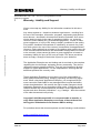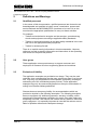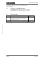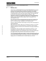
1
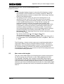
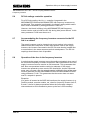
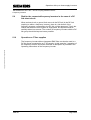
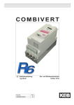
Application for Drive Technology
MICROMASTER 4
Application Description
MICROMASTER 420 / 440
DC link coupling between several frequency inverters
Warranty, Liability and Support
MICROMASTER 420 / 440 – DC link coupling between several
Frequency inverters
1
Warranty, Liability and Support
We do not accept any liability for the information contained in this document.
Copyright © Siemens AG 2005 All rights reserved
Any claims against us – based on whatever legal reason – resulting form
the use of the examples, information, programs, engineering and performance data etc., described in this document shall be excluded. Such an exclusion shall not apply in the case of mandatory liability, e.g. under the
German Product Liability Act (“Produkthaftungsgesetz”), in case of intent,
gross negligence, or injury of life, body or health, guarantee for the quality
of a product, fraudulent concealment of a deficiency or breach of a condition which goes to the root of the contract (“wesentliche Vertragspflichten”).
However, claims arising from a breach of a condition which goes to the root
of the contract shall be limited to the foreseeable damage which is intrinsic
to the contract, unless caused by intent or gross negligence or based on
mandatory liability for injury of life, body or health. The above provisions
does not imply a change in the burden of proof to your detriment.
The Application Examples are not binding and do not claim to be complete
regarding the circuits shown, equipping and any eventuality. They do not
represent customer-specific solutions. They are only intended to provide
support for typical applications. You are responsible in ensuring that the
described products are correctly used.
These Application Examples do not relieve you of the responsibility in
safely and professionally using, installing, operating and servicing equipment. When using these Application Examples, you recognize that Siemens cannot be made liable for any damage/claims beyond the liability
clause described above. We reserve the right to make changes to these
Application Examples at any time without prior notice. If there are any deviations between the recommendations provided in these Application Examples and other Siemens publications – e.g. Catalogs – then the contents
of the other documents have priority.
Copyright© 2005 Siemens A&D. It is not permissible to transfer or
copy these Application Examples or excerpts of them without first
having prior authorization from Siemens A&D in writing.
For questions about this document please use the following e-mail-address:
mailto:[email protected]
A&D SD
Page 2/32
Definitions and Warnings
MICROMASTER 420 / 440 – DC link coupling between several
Frequency inverters
2
Definitions and Warnings
2.1
Qualified personnel
In the sense of this documentation, qualified personnel are those who are
knowledgeable and qualified to install, mount, commission, operate and
service/maintain the MICROMASTER 4 products to be used. He or she
must have the appropriate qualifications to carry-out these activities.
For example:
o
Trained and authorized to energize and de-energize, ground and tag
circuits and equipment according to applicable safety standards.
o
Trained or instructed according to the latest safety standards in the care
and use of the appropriate safety equipment.
o
Trained in rendering first aid.
Copyright © Siemens AG 2005 All rights reserved
There is no explicit warning information in this documentation. However,
reference is made to warning information and instructions in the Operating
Instructions for the particular product.
2.2
User group
These application notes were drawn-up to support customers and
employees of Siemens AG when engineering plants and machines.
2.3
Exclusion of liability
The application examples are provided at no charge. They may be used
under the clear understanding that the party using them does so at his own
risk. They may only be passed-on to third parties, completely unchanged,
maintaining all of the confidential property notices. These application
examples may only be commercially passed-on after prior authorization in
writing from Siemens Aktiengesellschaft.
Siemens does not accept any liability for recommendations which are
provided or implied by the following description. The following description
does not represent any additional guarantee, warranty or liability, which
goes beyond Siemens general conditions for supply. Any other claims are
completely excluded. The authors and owners are only liable for willful and
gross negligence. It is especially important to note that the authors are not
liable for possible defects and subsequent damage.
A&D SD
Page 3/32
Definitions and Warnings
MICROMASTER 420 / 440 – DC link coupling between several
Frequency inverters
2.4
Information regarding trademarks
MICROMASTER® is a Siemens registered trademark
MASTERDRIVES® is a Siemens registered trademark
2.5
Revisions/author
Date/change
Author
1.1
14.10.03 / First edition in English language
Haßold
1.3
20.09.04 / Changes in Section “ Definitions and Warnings”;
additional note regarding the connection of the single phase
inverters to the mains in Section 3.1.
Haßold
Copyright © Siemens AG 2005 All rights reserved
Version
A&D SD
Page 4/32
Introduction
MICROMASTER 420 / 440 – DC link coupling between several
Frequency inverters
3
Introduction
The DC links of MICROMASTER 420 and MICROMASTER 440 frequency
inverters can be coupled with one another using the DC link coupling. In
this case, the frequency inverters exchange energy with one another
through the common DC link. When one or several frequency inverters are
in the regenerative mode, this means that the energy can be provided via
the DC link to the frequency inverters which are motoring . If the
regenerative energy is not completely utilized by the connected frequency
inverters, or not at every instant in time, than this can be dissipated in the
braking resistor using the braking chopper that it is integrated in the
MICROMASTER 440.
As a result of the energy exchange between the frequency inverters, less
energy is drawn from the line supply and, depending on the application,
less or no braking energy is dissipated in the braking resistor.
Drives for winders/unwinders and transport conveyor belts are examples of
typical applications.
Copyright © Siemens AG 2005 All rights reserved
With the DC link coupling, either only one frequency inverter or up to three
frequency inverters can be simultaneously connected to the line supply.
Additional frequency inverters can be connected to the supply inverters via
the DC link.
A configuration with one supply inverter is described in Section 2. This
arrangement is practical if the frequency inverters that are connected
predominantly operate in the regenerative mode or the supply inverter has
a far higher power rating than the connected frequency inverters.
The DC link coupling with several supply inverters connected in parallel (up
to 3 are possible) is described in Section 3. These can be especially used if
several drives which operate in the motoring mode are connected and the
supply power is to be distributed over several frequency inverters.
A&D SD
Page 5/32
Introduction
MICROMASTER 420 / 440 – DC link coupling between several
Frequency inverters
4
Operation with only one supply frequency inverter
With this configuration, only one frequency inverter is connected to the line
supply and one or several frequency inverters is/are connected to the
supply inverter through the DC link. This then provides the energy for the
frequency inverters coupled at the DC link.
3-ph. 200-240V AC 50/60Hz
3-ph. 380-480V AC 50/60Hz
L1
L2
L3
PE
Line fuses
Copyright © Siemens AG 2005 All rights reserved
Line
contactor
Line reactor
DC link fuses
PE
DC link fuses
PE
PE
MM440
MM440
MM420
30kW
1,5kW
1,5kW
Inverter
PE
PE
PE
Braking resistor
M
3~
M
3~
M
3~
Motor
Motor
Motor
Fig. 2-1: Block diagram of the DC link coupling with one supply inverter example for operation with a three-phase line supply
A&D SD
Page 6/32
Introduction
MICROMASTER 420 / 440 – DC link coupling between several
Frequency inverters
4.1
Frequency inverter versions and power ratings which can be
coupled
MICROMASTER 420 and MICROMASTER 440 frequency inverters can be
operated together as well as mixed in a DC link group. In mixed operation,
both frequency inverter types can be used as the supply inverter connected
to the line supply. The DC link coupling is possible with frequency inverters
which can be connected to the following line supplies:
o
1-ph. 200-240V AC
o
3-ph. 200-240V AC
o
3-ph. 380-480V AC
Copyright © Siemens AG 2005 All rights reserved
Notes:
o
It must be ensured that only frequency inverters having the same
voltage level 1/3-ph. 200-240V AC and 3-ph. 380-480V AC are
connected through the DC links.
o
When using the DC link coupling, only frequency inverters with a
maximum rated power of 75kW (CT) or 90kW (VT), (frame size F) may
be used.
o
In order not to overload the frequency inverter connected to the line
supply during pre-charging, a maximum load of 300% of the supply
inverter power may be connected to its DC link.
o
The maximum number of frequency inverters coupled via the DC link is
10 .
When engineering the drive system it is important to ensure that the rated
input current of the frequency inverter connected to the line supply is not
exceeded. The rated input currents are specified in Catalog DA51.2 and
Tables 2-1 and 2-2. However, the overload capacity of the frequency
inverter, specified in Catalog DA51.2, can be utilized. In practice, it
therefore makes sense to connect - as a maximum - the same power as
the supply inverter rating at its DC link.
This means, that in total, for the complete DC link group, only the power of
the supply frequency inverter can be drawn from the line supply. The DC
link coupling, described here, with one supply inverter is therefore practical
for applications where the frequency inverters connected to the DC link of
the supply inverter predominantly operate in the regenerative mode or the
power rating of the supply inverter is significantly higher than the connected
frequency inverters.
A&D SD
Page 7/32
Operation with only one supply frequency inverter
MICROMASTER 420 / 440 – DC link coupling between several
Frequency inverters
4.2
Options required at the line supply input of the supply inverter
The fuses, circuit-breaker and a possible externally mounted EMC filter
should be used, according to Catalog DA51.2, at the line side of the supply
inverter as for frequency inverters operated in the standalone mode.
Frequency inverters with integrated EMC filters can also be used as supply
inverter; for the frequency inverters connected to the DC link, an integrated
EMC filter makes no sense and is not necessary.
In order to ensure reliable operation of the drive group, the supply inverter
must always have a line reactor. The line reactor can be dimensioned using
Catalog DA51.2 just like the frequency inverters which are operated as
standalone units.
Copyright © Siemens AG 2005 All rights reserved
Note:
Under certain circumstances it is no longer guaranteed that the EMC limit
value classes are fully maintained. This is the reason that it is absolutely
necessary that the EMC Guidelines, specified in the frequency inverter
Operating Instructions are carefully maintained.
4.3
Engineering the DC link couplings
When engineering the DC link couplings, it must be noted that the DC link
current IDC, provided by the supply inverter, does not correspond exactly to
the line current IN (specified in Tables 2-1 and 2-2). The DC link current IDC
can be more precisely specified in relationship to the frequency inverter
output current IA . The DC link current IDC is then given by:
IDC = 1.35 • IA • cosϕ Motor •
VA
1
•
V max ηINV
In this case:
IDC
=
DC link current at the DC link terminals of the
frequency inverter
A&D SD
IA
=
frequency inverter output current (motor current)
cosφMotor
=
motor power factor
VA
=
frequency inverter output voltage
Vmax
=
max. frequency inverter output voltage
ηINV
=
efficiency of the inverter module
Page 8/32
Operation with only one supply frequency inverter
MICROMASTER 420 / 440 – DC link coupling between several
Frequency inverters
In order to simplify the equation, the following assumptions are made:
cosφMotor
=
0.86
VA / Vmax
=
1 (operation at the max. frequency inverter voltage)
ηINV
=
0.97
This means the following:
IDC = 1.20 • IA
At the rated operating point with the rated output current IAN:
IDCN = 1.20 • IAN
Copyright © Siemens AG 2005 All rights reserved
The rated currents and the required DC link fuses of the
MICROMASTER420 and MICROMASTER440 frequency inverters are
listed in the following Tables 2-1 and 2-2.
A&D SD
Page 9/32
Operation with only one supply frequency inverter
MICROMASTER 420 / 440 – DC link coupling between several
Frequency inverters
Rated currents and recommended DC link fuses of the MICROMASTER 420/440 inverters, versions
without/with filter
CT (Constant Torque)
Power
Rated input
current
Rated
output
current
Rated DC
link current
kW
A
A
A
VT (Variable Torque)
Required DC link fuses
2x per converter are
required
Order No.
Required DC link fuses
2x per converter are
required
Power
Rated input
current
Rated
output
current
Rated DC
link current
kW
A
A
A
Order No.
A
A
Line supply voltage, 1-ph. 200V to 240V AC
Copyright © Siemens AG 2005 All rights reserved
0,12
0,25
0,37
0,55
0,75
1,1
1,5
2,2
3
1,4
2,7
3,7
5,0
6,6
9,6
13,0
17,6
23,7
0,9
1,7
2,3
3,0
3,9
5,5
7,4
10,4
13,6
1,1
2,0
2,8
3,6
4,7
6,6
8,9
12,5
16,3
3NC1402
3NC1404
3NC1405
3NC1405
3NC1406
3NC1410
3NC1415
3NC1420
3NC1425
2
4
5
5
6
10
15
20
25
-
-
-
-
-
-
3NC1402
3NC1404
3NC1405
3NC1405
3NC1406
3NC1410
3NC1415
3NC1420
3NC1425
3NC1430
3NC1432
3NC1440
3NC2263
3NC2280
3NC2200
2x3NC2280
2x3NC2200
2x3NC2200
3x3NC2280
2
4
5
5
6
10
15
20
25
30
32
40
63
80
100
2x80
2x100
2x100
3x80
-
-
-
-
-
5,5
7,5
11
15
18,5
22
30
37
45
-
17,6
26,5
38,4
50,3
61,5
70,8
96,2
114,1
134,9
-
22,0
28,0
42,0
54,0
68,0
80,0
104,0
130,0
154,0
-
26,4
33,6
50,4
64,8
81,6
96,0
124,8
156,0
184,8
-
3NC1432
3NC1440
3NC2263
3NC2280
3NC2200
2x3NC2280
2x3NC2200
2x3NC2200
3x3NC2280
-
Line supply voltage, 3-ph. 200V to 240V AC
0,12
0,25
0,37
0,55
0,75
1,1
1,5
2,2
3
4
5,5
7,5
11
15
18,5
22
30
37
45
0,6
1,1
1,6
2,1
2,9
4,1
5,6
7,6
10,5
13,1
17,5
25,3
37,0
48,8
61,0
69,4
94,1
110,6
134,9
0,9
1,7
2,3
3,0
3,9
5,5
7,4
10,4
13,6
17,5
22,0
28,0
42,0
54,0
68,0
80,0
104,0
130,0
154,0
1,1
2,0
2,8
3,6
4,7
6,6
8,9
12,5
16,3
21,0
26,4
33,6
50,4
64,8
81,6
96,0
124,8
156,0
184,8
32
40
63
80
100
2x80
2x100
2x100
3x80
-
Table 2-1:
Rated currents and required DC link fuses of the MICROMASTER420 and
MICROMASTER440 frequency inverters with a line supply voltage 1/3-ph. 200-240V AC
Possible cylindrical fuse disconnectors:
for fuses 3NC14.. :
for fuses 3NC22.. :
3NC1492
3NC229x
Note:
The cylindrical fuse disconnectors may only be
switched when in a no-current condition.
A&D SD
Page 10/32
Operation with only one supply frequency inverter
MICROMASTER 420 / 440 – DC link coupling between several
Frequency inverters
Rated currents and recommended DC link fuses of the MICROMASTER 420/440 drive converters, versions
without/with filter
CT (Constant Torque)
Power
Rated input
current
Rated
output
current
Rated DC
link current
kW
A
A
A
VT (Variable Torque)
Required DC link fuses
2x per converter are
required
Order No.
A
Power
Rated input
current
Rated
output
current
Rated DC
link current
kW
A
A
A
-
-
-
-
7,5
11
15
18,5
22
30
37
45
55
75
90
16,0
22,5
30,5
37,2
43,3
59,3
71,7
86,6
103,6
138,5
168,5
19,0
26,0
32,0
38,0
45,0
62,0
75,0
90,0
110,0
145,0
178,0
22,8
31,2
38,4
45,6
54,0
74,4
90,0
108,0
132,0
174,0
213,6
Required DC link fuses
2x per converter are
required
Order No.
A
Copyright © Siemens AG 2005 All rights reserved
Line supply voltage, 3-ph. 380V to 480V AC
0,37
0,55
0,75
1,1
1,5
2,2
3
4
5,5
7,5
11
15
18,5
22
30
37
45
55
75
1,1
1,4
1,9
2,8
3,9
5,0
6,7
8,5
11,6
15,4
22,5
30,0
36,6
43,1
58,7
71,2
85,6
103,6
138,5
1,3
1,7
2,2
3,1
4,1
5,9
7,7
10,2
13,2
19,0
26,0
32,0
38,0
45,0
62,0
75,0
90,0
110,0
145,0
1,6
3NC1402
2
2,0
3NC1404
4
2,6
3NC1405
5
3,7
3NC1405
5
4,9
3NC1406
6
7,1
3NC1410
10
9,2
3NC1415
15
12,2
3NC1415
15
15,8
3NC1420
20
22,8
3NC1430
30
31,2
3NC1440
40
38,4
3NC1450
50
45,6 3NE8018-1
63
54,0 3NE8020-1
80
74,4 3NE8021-1 100
90,0 3NE8021-1 100
108,0 3NE8022-1 125
132,0 3NE8024-1 160
174,0 2x3NE8021-1 2x100
3NC1430
30
3NC1440
40
3NC1450
50
3NE8018-1
63
3NE8020-1
80
3NE8021-1 100
3NE8021-1 100
3NE8022-1 125
3NE8024-1 160
2x3NE8021-1 2x100
2x3NE8022-1 2x125
Table 2-2:
Rated currents and required DC link fuses of the MICROMASTER420 and
MICROMASTER440 frequency inverters with a line supply voltage
3-ph. 380-480V AC.
Possible fuse disconnectors:
for fuses 3NC14.. :
for fuses 3NE80.. :
Note:
3NC1492
3NP40
The fused disconnectors may only be switched when
in a no-current condition. Used in compliance with
degree of pollution 2.
A&D SD
Page 11/32
Operation with only one supply frequency inverter
MICROMASTER 420 / 440 – DC link coupling between several
Frequency inverters
4.3.1
Connecting the DC link coupling at the frequency inverter
The DC link couplings are connected at terminals DC + und DC – of the
frequency inverter. Terminals DC + are connected with DC + and DC – with
DC – of the frequency inverter. If frequency inverters whose rated powers
differ significantly, are coupled with one another, then it should be noted
that the small cable cross-sections of the lower rating frequency inverter
may not be directly connected to the higher rating frequency inverter at the
DC link. In this case, a suitable reduction should be used.
Note:
It is extremely important to ensure that the polarity of the DC link coupling is
not interchanged as otherwise the connected frequency inverters could be
destroyed.
Copyright © Siemens AG 2005 All rights reserved
4.3.2
Cable cross-sections required and implementing the DC link
couplings
The cable cross-sections required are obtained from the power rating of the
frequency inverters connected to the supply inverter. The cable crosssection is selected starting from the supply inverter corresponding to the
sum of the powers connected there and the resulting sum of all of the DC
link currents. The cable cross-section can be lower the greater the distance
to the supply point if the total connected power of the frequency inverters in
the particular section of the line is lower. As an alternative, a DC bus bar,
connected to the supply inverter can be used.
The DC link currents which flow for each frequency inverter (at the rated
operating point) are specified above under Point 2.3. The sum of the DC
link currents of the frequency inverters connected to the supply inverter are
then used to select the cable cross-section of the DC link connection. In
addition, the type of cable routing and ambient temperature must be taken
into account.
The DC link couplings must be appropriately implemented for the voltages
which occur. The voltage strength required is as follows:
o
450V DC
for a line supply voltage of 1/3-ph. 200-240V AC
o
900V DC
for a line supply voltage of 3-ph. 380-480V AC
In order to reduce EMC noise, shielded cables must be used for the DC link
coupling. The shield should be connected at both ends through the largest
possible surface area. For frequency inverter sizes A, B and C, the optional
A&D SD
Page 12/32
Operation with only one supply frequency inverter
MICROMASTER 420 / 440 – DC link coupling between several
Frequency inverters
gland plate can be used. For the DC link fuses, the shield should be
connected to the mounting plate.
Note:
When implementing the DC link couplings, it is also important that the
plant/system and country-specific regulations are carefully observed.
4.3.3
Fusing the frequency inverter and the DC link couplings
Copyright © Siemens AG 2005 All rights reserved
The DC link fusing depends on the cross-section of the DC link coupling
and the max. possible fusing of the individual frequency inverters connected
at the DC link. The supply inverter is fused on the line side using fuses
recommended in the Operating Instructions of the MICROMASTER420 and
MICROMASTER440 frequency inverters; the frequency inverters which are
connected to the supply inverter must be fused at the DC link input of the
frequency inverter using the fuses specified in Tables 2-1 and 2-2. Fuses
must be provided in both the positive and negative arm of the DC link.
Note:
If the DC link coupling, originating from the supply inverter, is no longer
fused using the line-side fuses as a result of the low cable cross-section,
then this must be fused (protected) as close as possible to the supply
inverter. The fuses, specified in Tables 2-1 and 2-2 can be used for this
purpose. If the sum of the powers of the frequency inverters connected to
the DC link is less than that of the supply inverter, then this can also be
fused at the DC circuit output using fuses which have a lower rated current.
The rated current of the particular DC link fuses is then dependent on the
connected power and the cable cross-section used for the DC link
connection. The cables up to the fuses must be implemented and routed so
that they are short-circuit proof.
It is not necessary to use DC link fuses and short-circuit proof cabling, if
o
the frequency inverters, connected to the DC link have the same line
fuses - as specified in the Operating Instructions - as for the supply
inverter,
and
o
A&D SD
the cable cross-section of the DC link coupling is implemented so that
this is fused using the fuses on the line side. In this case it should be
observed that the rated DC link current IDCN, specified in Tables 2-1
and 2-2, is higher than the rated input current of the frequency inverter.
Page 13/32
Operation with only one supply frequency inverter
MICROMASTER 420 / 440 – DC link coupling between several
Frequency inverters
Note:
When fusing/protecting the frequency inverters and DC link couplings, it is
also important that the plant/system and country-specific regulations are
carefully observed.
Example 1:
L1
3-ph. 380-480V AC 50/60Hz
L2
L3
PE
Line fuses
3 x 200A
Copyright © Siemens AG 2005 All rights reserved
Line
contactor
Cable cross-section
2 x 25mm²
Line reactor
2 x 40A
2 x 80A
Short-circuit
proof
implementation
and routing
PE
PE
2 x 32A
PE
MM440
MM440
MM420
75kW
(CT)
11kW
(CT)
7,5kW
Inverter
PE
PE
PE
M
3~
M
3~
M
3~
Motor
Motor
Motor
Fig. 2-2: DC link coupling of a 75kW MM440 frequency inverter with an
11kW MM440 and a 7.5kW MM420
A&D SD
Page 14/32
Operation with only one supply frequency inverter
MICROMASTER 420 / 440 – DC link coupling between several
Frequency inverters
Copyright © Siemens AG 2005 All rights reserved
In this particular case, the supply inverter (75kW) is fused, on the line side
with the fuses (200A) specified in the Operating Instructions. The frequency
inverters (11kW and 7.5kW) connected to its DC link must be separately
fused as they cannot be protected by the 200A line fuses of the supply
inverter. The two connected inverters are fused through two phases with
40A (11kW frequency inverter) and 32A (7.5kW frequency inverter)
according to Table 2-2. This means that the DC link coupling must be also
directly fused at the DC link output of the 75kW frequency inverter (with 2x
80A fuses). The reason for this is that this also cannot be protected by the
200A line fuses because of the 25mm² cross-section being used. The
cross-section of the DC link coupling depends on the total rated DC link
currents (IDCtot = 54A) of the frequency inverters connected to the supply
inverter. Depending on the cable routing type and the ambient temperature,
a cross-section of, e.g. 25mm² can be used (routing type B1, 2 conductors
conducting current, 40° C ambient temperature). The cable coupling
between the DC link connection of the 75kW frequency inverter up to the
fuses of the DC link coupling should be as short as possible and be
implemented and routed so that it is short-circuit proof. As an alternative to
a short circuit-proof implementation and routing, a cable cross-section can
be used for this coupling which is adequately protected using the 200A line
fuses (depending on the line impedance, the DC link current is
approximately 20% higher than the line current).
A&D SD
Page 15/32
Operation with only one supply frequency inverter
MICROMASTER 420 / 440 – DC link coupling between several
Frequency inverters
Example 2:
3-ph. 380-480V AC 50/60Hz
L1
L2
L3
PE
Line fuses
3 x 10A
Line
contactor
Line reactor
PE
Inverter
PE
MM440
MM440
MM420
1,5kW
0,55kW
0,55kW
PE
Copyright © Siemens AG 2005 All rights reserved
PE
PE
PE
M
3~
M
3~
M
3~
Motor
Motor
Motor
Fig. 2-3: DC link coupling of a 1.5kW MM440 frequency inverter with an
0.55kW MM440 and a 0.55kW MM420
In this particular case, the DC link does not have to be fused, because:
A&D SD
o
All of the frequency inverters require line fuses of 3x10A and these are
used at the input of the supply inverter.
o
The total DC link current (summed) of the two connected frequency
inverters each with 0.55kW is, according to Table 2-2 IDCtot = 2*2A = 4A.
For this current, a cross-section of 1.5mm² (routing type B2, 2
conductors conducting current, 40°C ambient temperature) can be used
which are adequately protected using the 3x10A line fuses.
Page 16/32
Operation with only one supply frequency inverter
MICROMASTER 420 / 440 – DC link coupling between several
Frequency inverters
4.3.4
Maximum DC link - cable lengths
The total length of the DC link couplings as a sum, starting from the supply
inverter is 5m.
4.4
Braking operation of the DC link group
For the DC link coupling, energy is exchanged between the frequency
inverters through a common DC link. This means that if one or several
frequency inverters is regenerating, then this energy can be provided to the
frequency inverters which are motoring. If the regenerative energy is not
completely drawn by the connected frequency inverters - or not at every
instant in time - then the energy can be dissipated in a connected braking
resistor using the braking chopper that is integrated in the MICROMASTER
440.
Copyright © Siemens AG 2005 All rights reserved
In the DC link group, the internal braking chopper may only be activated for
one MICROMASTER 440 frequency inverter. It makes sense if the
MICROMASTER 440 in the DC link with the highest power rating is used for
this purpose. The required braking resistor can be selected in accordance
with the data in Catalog DA51.2.
Note:
A&D SD
o
The integrated braking chopper is only active if the frequency inverter
had received an ON command and is actually operational. When the
appropriate frequency inverter is powered-down, then energy cannot be
pulsed in the braking resistor.
o
The braking resistors, which are used in the Catalog DA51.2, are
specified for a duty cycle of 5%. The duty cycle can be increased
corresponding by using several braking resistors with a duty cycle of 5%
or other suitable braking resistors. For the DC link coupling, the
regenerative energy could also be supplied from (several) other
inverters. In this case it must be ensured, that the braking power which
is dissipated in continuous operation in the braking resistor does not
exceed the rated power PINVN of the braking inverter. The maximum
short-time braking power Pbrakeshort can be calculated with the minimum
possible restistance of the braking resistor Rmin (Table 5-4 of the
MICROMASTER 440 Operating instructions) and the maximum possible
DC link voltage VDCmax
(DC 420V at 230V-units resp. DC 840V at 400V-units).
This means the following: Pbrakeshort = VDCmax² / Rmin
For the DC link coupling the highest permitted value of the duty cycle x
in the Parameter 1237 at MICROMASTER 440 is: x ≤ (PINV N / Pbrake short
) * 100%
Page 17/32
Operation with only one supply frequency inverter
MICROMASTER 420 / 440 – DC link coupling between several
Frequency inverters
The DC braking – function in the inverter can be used as an alternative to
regenerative braking using the integrated braking chopper. This can be
activated for every connected frequency inverter. It is not permissible that
the compound braking is activated. The reason for this is that this can
automatically be switched-in, as a function of the DC link voltage and result
in undesirable braking operations.
4.5
Max. motor cable lengths
Copyright © Siemens AG 2005 All rights reserved
The max. motor cable length of all of the frequency inverters connected in
the DC link group may not exceed, in total, 200m (shielded) and 300m
(non-shielded). Otherwise, their rectifier and the EMC filters could be
overloaded due to the discharge (leakage currents) which flow with respect
to PE and which flow back through the supply inverter. An output reactor
should be used for the individual frequency inverters for motor cable lengths
exceeding 50m (shielded) and 100m (non-shielded) as specified in Catalog
DA51.2.
4.6
DC link voltage controller operation
For a DC link coupling, the VDCmax controller, integrated in the
MICROMASTER 420 and MICROMASTER 440 frequency inverters may
not be used. This controller is activated in the factory setting which means
that it must be disabled by setting parameter P1240 to 0.
However, the kinetic buffering in the MICROMASTER 440 frequency
inverter can be used to buffer the DC link during brief power failures. In this
case, parameter P1240 must be set to 2.
4.7
Accommodating the frequency inverters connected to the DC
link in a cabinet
The frequency inverters, coupled through the DC link, must be located next
to one another in the electric cabinet in the same sequence as their rated
powers. Generally, the supply inverter is the inverter with the highest power
rating in the DC link group. The frequency inverters must be arranged
directly next to one another in order to keep the DC link couplings as short
as possible.
A&D SD
Page 18/32
Operation with only one supply frequency inverter
MICROMASTER 420 / 440 – DC link coupling between several
Frequency inverters
4.8
Operation of the fans in the frequency inverters
In order that the supply inverter is not thermally overloaded, when one of
the connected frequency inverters receives an ON command then the
supply inverter must also receive an ON command. This therefore
guarantees that its fan is operational and the cooling is adequate. If the
supply inverter is powered-up as a result of the internal fan, but the
connected motor may not rotate, then the setpoint can be inhibited in front
of the ramp-function generator for both MICROMASTER420 and
MICROMASTER440 using parameter P1142. This guarantees that the
motor does not rotate even if a setpoint is present.
Exception:
Copyright © Siemens AG 2005 All rights reserved
If an option is inserted at the BOP link interface at the supply inverter (e.g.
Profibus module, encoder module, etc.) then for frequency inverter sizes A,
B, and C, the fan is always operational when the line supply voltage is
connected and an ON command to power-up the fan is not necessary.
4.9
Risk for the connected frequency inverters in the case of a DC
link short-circuit
When a short-circuit or ground fault occurs in the DC link (in the DC link
coupling or within a frequency inverter), there is a risk that all of the
frequency inverters, connected to the DC link, will be destroyed. This is the
reason that when the drive system is engineered, this aspect should be
carefully taken into account. The number of frequency inverters within a DC
link group should be kept as low as possible.
4.10
Operation on IT line supplies
The frequency inverter without integrated EMC filter can also be used in a
DC link group connected to an IT line supply. In this case the Y capacitor of
the frequency inverter should be removed. A description is provided in the
Operating Instructions of the frequency inverter.
A&D SD
Page 19/32
Operation with only one supply frequency inverter
MICROMASTER 420 / 440 – DC link coupling between several
Frequency inverters
5
Operation with up to three supply inverters
If several drives predominantly operate in the motoring mode in a DC link
group, then one supply inverter is no longer sufficient. In this case up to
three frequency inverters can be connected to the line supply and coupled
through the DC link. Additional frequency inverters can be connected to this
DC link group and supplied.
3-ph. 200-240V AC 50/60Hz
3-ph. 380-480V AC 50/60Hz
L1
L2
L3
PE
Line
contactor
Copyright © Siemens AG 2005 All rights reserved
Line fuses
Line reactors /
DC link fuses
PE
Inverter
PE
PE
PE
PE
MM440
MM440
MM420
MM440
MM420
22kW
15kW
11kW
1,5kW
1,5kW
PE
PE
PE
PE
PE
Braking resistor
M
3~
M
3~
M
3~
M
3~
M
3~
Motor
Motor
Motor
Motor
Motor
Fig. 3-1: Block circuit diagram of a DC link coupling with three supply inverters,
example for operation with a three-phase line supply
A&D SD
Page 20/32
Operation with up to three supply inverters
MICROMASTER 420 / 440 – DC link coupling between several
Frequency inverters
5.1
Frequency inverter versions and power ratings which can be
coupled
MICROMASTER 420 and MICROMASTER 440 frequency inverters can be
operated both with one another as well as mixed in a DC link group. In
mixed operation, both frequency inverter types can be used as the supply
frequency inverter connected to the line supply. The DC link coupling is
possible with frequency inverters which can be connected to the following
line supplies:
o
1-ph. 200-240V AC
o
3-ph. 200-240V AC
o
3-ph. 380-480V AC
Copyright © Siemens AG 2005 All rights reserved
Note:
A&D SD
o
It must be ensured that only frequency inverters having the same
voltage level 1/3-ph. 200-240V AC and 3-ph. 380-480V AC are
connected through the DC links.
o
Only single-phase or three-phase frequency inverters may be used as
supply inverter. It is not permissible to mix 1-ph. AC and 3-ph. AC
frequency inverters
(200-240V drive units) as supply inverter.
o
When using single phase frequency inverters (1-ph. 200-240V AC) as
supply inverters, it is extremely important to ensure that all of the supply
inverters are connected to the same line phase (e.g. L1/N), otherwise
the connected frequency inverters could be destroyed.
o
When using the DC link coupling, only frequency inverters with a
maximum rated power of 75kW (CT) or 90kW (VT), (housing size F) may
be used.
o
The difference between the power ratings of the supply inverters may
not be greater than 1:3 in order that the smaller supply frequency
inverter is not overloaded. This restriction does not apply to the
frequency inverters which are not feeding the drive system. This means
that these frequency inverters can be dimensioned significantly smaller
than the supply inverters.
o
The maximum number of supply inverters is 3. A maximum of 7
additional frequency inverters, which are not directly connected to the
line supply, can be connected to the DC link. The sum of the frequency
inverters, coupled through the DC link, may be up to 10 units.
o
The supply inverter must be dimensioned by a factor of 1.35 greater
than it would be to cover all of the motoring power connected to the DC
link. The reason for this is the equalization currents which flow between
Page 21/32
Operation with up to three supply inverters
MICROMASTER 420 / 440 – DC link coupling between several
Frequency inverters
Copyright © Siemens AG 2005 All rights reserved
the individual frequency inverters. This can therefore avoid overloading
the rectifier integrated in the frequency inverter. The frequency inverters
which are not used to supply the DC link group do not have to be
overdimensioned and can be dimensioned corresponding to the
connected motor load.
o
When engineering the drive system it is important to ensure that the
frequency inverters, connected to the line supply, can have a max. load
which represents 74% of the rated input current on the input side
(overdimensioned by a factor of 1.35x). The drive group must therefore
be engineered so that the complete motoring power of the frequency
inverters does not exceed 74% of the sum of the rated powers of the
frequency inverters connected to the line supply. However, in addition,
frequency inverters connected to the DC link can be operated in the
regenerative mode so that they do not represent a load for the supply
inverter.
o
In order not to overload the frequency inverters connected to the line
supply when pre-charging, the maximum load which can be additionally
connected to the DC link is the sum of the rated powers of the supply
inverters. This applies for frequency inverters operating in the motoring
mode as well as in the regenerative mode.
Engineering example to check the required supply power:
DC link coupling with 3 supply inverters and 2 frequency inverters
connected through the DC link.
Motor power of the supply inverters: 11kW, 15kW, 22kW
Motor power of the frequency inverters connected to the DC link: 2 x 7.5kW
The motors of the supply inverters predominantly operate in the motoring
mode, one frequency inverter which is not a supply inverter, (7.5kW)
operates in the regenerative mode and the other frequency inverter which is
not used as supply inverter (7.5kW), operates in the motoring mode.
The following check is necessary because of the necessity to
overdimension the supply inverter by a factor of 1.35:
Sum of the motoring powers:
Pmottot = 11kW+15kW+22kW+7.5kW = 55.5kW
Required supply power:
PSUPPLYtot = Pmottot * 1.35 = 55.5kW * 1.35 = 75kW
A&D SD
Page 22/32
Operation with up to three supply inverters
MICROMASTER 420 / 440 – DC link coupling between several
Frequency inverters
The required supply power of 75kW can, for example, be split-up as follows:
Motor power of the
supply inverters:
Required power of the
supply inverters:
11kW
=>
15kW (overdimensioned by a factor of 1.35)
15kW
=>
30kW 1)
22kW
=>
30kW (overdimensioned by a factor of 1.35)
1)
Overdimensioned by more than a factor of 1.35 as a frequency inverter
which is not a supply inverter operates in the motoring mode and the total
supply power must be at least 1.35 times larger than the sum of the
motoring powers in the drive group.
Copyright © Siemens AG 2005 All rights reserved
The frequency inverters connected to the DC link do not have to be
overdimensioned. This means that 2 frequency inverters, each with a
7.5kW power rating can be used.
5.2
Options which are required at the line supply input of the supply
inverters
The fuses, circuit-breaker and a possible externally mounted EMC filter
should be used, according to Catalog DA51.2 at the line side of the supply
inverter just the same as for the individually operated frequency inverters.
The supply inverters must be overdimensioned by a factor of 1.35. This
means that the line-side options also have to be dimensioned for a higher
rating. In turn this means that the line-side options can be selected
corresponding to the power rating of the supply inverters. In order to limit
the equalization currents between the supply inverters it is absolutely
necessary that each supply inverter has its own line reactor which matches
the power rating of the supply inverter. In order to achieve a symmetrical
pre-charging of the frequency inverters, the supply inverters must be
simultaneously switched-in using a common line contactor.
We recommend that the line-side fuses of the frequency inverter are
monitored so that the complete drive group can be powered-down when a
fuse ruptures.
Otherwise the frequency inverters still connected to the line supply would
have to compensate for the disconnected supply inverter and could
therefore be possibly overloaded.
Frequency inverters with integrated radio suppression filters can also be
used as supply inverters. For frequency inverters connected to the DC link,
an integrated EMC filter makes no sense and is not necessary.
A&D SD
Page 23/32
Operation with up to three supply inverters
MICROMASTER 420 / 440 – DC link coupling between several
Frequency inverters
Note:
Under certain circumstances it is no longer guaranteed that the EMC limit
value classes will be able to be fully maintained. It is therefore absolutely
necessary that the EMC Guidelines, specified in the frequency inverter
Operating Instructions are carefully maintained.
5.3
Engineering the DC link couplings
When engineering the DC link connections, it must be noted that the DC
link current IDC, provided by the supply inverter, does not correspond
exactly to the line current IN (specified in Tables 3-1 and 3-2). The DC link
current IDC can be more precisely specified in relationship to the frequency
inverter output current IA . The DC link current IDC is then given by:
Copyright © Siemens AG 2005 All rights reserved
IDC = 1 .35 • IA • cos ϕ Motor •
1
VA
•
V max η INV
In this case:
=
IDC
DC link current at the DC link terminals of the
frequency inverter
IA
=
frequency inverter output current (motor current)
cosφMotor
=
motor power factor
VA
=
frequency inverter output voltage
Vmax
=
max. frequency inverter output voltage
ηINV
=
efficiency of the inverter module
In order to simplify the equation, the following assumptions are made:
cosφMotor
=
0.86
VA / Vmax
=
1 (operation at the max. frequency inverter voltage)
ηINV
=
0.97
This means the following:
IDC = 1.20 • IA
At the rated operating point with the rated output current IAN:
IDCN = 1.20 • IAN
A&D SD
Page 24/32
Operation with up to three supply inverters
MICROMASTER 420 / 440 – DC link coupling between several
Frequency inverters
The rated currents and the required DC link fuses of the
MICROMASTER420 and MICROMASTER440 frequency inverters are
listed in the following Tables 3-1 and 3-2.
Rated currents and recommended DC link fuses for MICROMASTER 420/440 inverters, versions with/without
filter
CT (Constant Torque)
Power
Rated input
current
Rated
output
current
Rated DC
link current
kW
A
A
A
VT (Variable Torque)
Required DC link fuses
2x per converter are
required
Order No.
A
Required DC link fuses
2x per converter are
required
Power
Rated input
current
Rated
output
current
Rated DC
link current
kW
A
A
A
Order No.
A
Copyright © Siemens AG 2005 All rights reserved
Line supply voltage, 1-ph. 200V to 240V AC
0,12
0,25
0,37
0,55
0,75
1,1
1,5
2,2
3
1,4
2,7
3,7
5,0
6,6
9,6
13,0
17,6
23,7
0,9
1,7
2,3
3,0
3,9
5,5
7,4
10,4
13,6
1,1
2,0
2,8
3,6
4,7
6,6
8,9
12,5
16,3
3NC1402
3NC1404
3NC1405
3NC1405
3NC1406
3NC1410
3NC1415
3NC1420
3NC1425
2
4
5
5
6
10
15
20
25
-
-
-
-
-
-
3NC1402
3NC1404
3NC1405
3NC1405
3NC1406
3NC1410
3NC1415
3NC1420
3NC1425
3NC1430
3NC1432
3NC1440
3NC2263
3NC2280
3NC2200
2x3NC2280
2x3NC2200
2x3NC2200
3x3NC2280
2
4
5
5
6
10
15
20
25
30
32
40
63
80
100
2x80
2x100
2x100
3x80
-
-
-
-
-
5,5
7,5
11
15
18,5
22
30
37
45
-
17,6
26,5
38,4
50,3
61,5
70,8
96,2
114,1
134,9
-
22,0
28,0
42,0
54,0
68,0
80,0
104,0
130,0
154,0
-
26,4
33,6
50,4
64,8
81,6
96,0
124,8
156,0
184,8
-
3NC1432
3NC1440
3NC2263
3NC2280
3NC2200
2x3NC2280
2x3NC2200
2x3NC2200
3x3NC2280
-
Line supply voltage, 3-ph. 200V to 240V AC
0,12
0,25
0,37
0,55
0,75
1,1
1,5
2,2
3
4
5,5
7,5
11
15
18,5
22
30
37
45
0,6
1,1
1,6
2,1
2,9
4,1
5,6
7,6
10,5
13,1
17,5
25,3
37,0
48,8
61,0
69,4
94,1
110,6
134,9
0,9
1,7
2,3
3,0
3,9
5,5
7,4
10,4
13,6
17,5
22,0
28,0
42,0
54,0
68,0
80,0
104,0
130,0
154,0
1,1
2,0
2,8
3,6
4,7
6,6
8,9
12,5
16,3
21,0
26,4
33,6
50,4
64,8
81,6
96,0
124,8
156,0
184,8
32
40
63
80
100
2x80
2x100
2x100
3x80
-
Table 3-1:
Rated currents and the required DC link fuses of the MICROMASTER420
and MICROMASTER440 frequency inverters with a line supply voltage 1/3-ph. 200-240V
AC
Possible cylindrical fuse disconnectors:
for fuse 3NC14.. :
for fuse 3NC22.. :
A&D SD
3NC1492
3NC229x
Page 25/32
Operation with up to three supply inverters
MICROMASTER 420 / 440 – DC link coupling between several
Frequency inverters
Note:
The cylindrical fuse disconnectors may only be switched when in
a no-current condition.
Rated currents and recommended DC link fuses for MICROMASTER 420/440 inverters, versions with/without
filter
CT (Constant Torque)
Power
Rated input
current
Rated
output
current
Rated DC
link current
kW
A
A
A
VT (Variable Torque)
Required DC link fuses
2x per converter are
required
Order No.
A
Power
Rated input
current
Rated
output
current
Rated DC
link current
kW
A
A
A
-
-
-
-
7.5
11
15
18.5
22
30
37
45
55
75
90
16.0
22.5
30.5
37.2
43.3
59.3
71.7
86.6
103.6
138.5
168.5
19.0
26.0
32.0
38.0
45.0
62.0
75.0
90.0
110.0
145.0
178.0
22.8
31.2
38.4
45.6
54.0
74.4
90.0
108.0
132.0
174.0
213.6
Required DC link fuses
2x per converter are
required
Order No.
A
Copyright © Siemens AG 2005 All rights reserved
Line supply voltage, 3-ph. 380V to 480V
0.37
0.55
0.75
1.1
1.5
2.2
3
4
5.5
7.5
11
15
18.5
22
30
37
45
55
75
1.1
1.4
1.9
2.8
3.9
5.0
6.7
8.5
11.6
15.4
22.5
30.0
36.6
43.1
58.7
71.2
85.6
103.6
138.5
1.3
1.7
2.2
3.1
4.1
5.9
7.7
10.2
13.2
19.0
26.0
32.0
38.0
45.0
62.0
75.0
90.0
110.0
145.0
1.6
3NC1402
2
2.0
3NC1404
4
2.6
3NC1405
5
3.7
3NC1405
5
4.9
3NC1406
6
7.1
3NC1410
10
9.2
3NC1415
15
12.2
3NC1415
15
15.8
3NC1420
20
22.8
3NC1430
30
31.2
3NC1440
40
38.4
3NC1450
50
45.6 3NE8018-1
63
54.0 3NE8020-1
80
74.4 3NE8021-1 100
90.0 3NE8021-1 100
108.0 3NE8022-1 125
132.0 3NE8024-1 160
174.0 2x3NE8021-1 2x100
3NC1430
30
3NC1440
40
3NC1450
50
3NE8018-1
63
3NE8020-1
80
3NE8021-1 100
3NE8021-1 100
3NE8022-1 125
3NE8024-1 160
2x3NE8021-1 2x100
2x3NE8022-1 2x125
Table 3-2:
Rated currents and required DC link fuses of the MICROMASTER420 and
MICROMASTER440 frequency inverters with a line supply voltage 3-ph. 380-480V AC.
Possible fuse disconnectors:
for fuse 3NC14.. :
for fuse 3NE80.. :
3NC1492
3NP40...
The fused disconnectors may only be switched when in a noNote:
current condition. Used in compliance with degree of pollution 2.
A&D SD
Page 26/32
Operation with up to three supply inverters
MICROMASTER 420 / 440 – DC link coupling between several
Frequency inverters
5.3.1
Connecting the DC link coupling at the frequency inverter
The DC link connections are connected at the frequency inverter at
terminals
DC + und DC – . Terminals DC + are connected with DC + and DC – with
DC – of the frequency inverter.
Note:
It is extremely important to ensure that the polarity of the DC link
connections is not interchanged as otherwise the connected frequency
inverters could be destroyed.
5.3.2
Cable cross-sections required and fusing of DC link couplings
Copyright © Siemens AG 2005 All rights reserved
When selecting the cable cross-sections required, the DC link coupling
differs in two different areas:
a. The cross-sections of the cables used to establish the DC link couplings
of the frequency inverter to the associated DC link fuses are
dimensioned corresponding to the DC link fuses of the frequency
inverter. This applies both for the supply inverters as well as for the
frequency inverters coupled through the DC link. For the supply
inverters, this connection must also be implemented and routed so that it
is short-circuit proof.
b. The cross-sections of the cables after the DC link fuses to connect the
drive inverters with one another are dimensioned so that these
correspond to the sum of the rated currents of the line fuses of all supply
inverters multiplied by a factor of 1.2.
Further, the routing type and ambient temperature of the DC link coupling
must be taken into account. As an alternative to using cables to establish
the DC link coupling, after the DC link fuses, a DC busbar, routed in
parallel, can be used. This low-inductance coupling offers the advantage
that the equalization currents between the supply inverters can be reduced
- thus reducing the load on the inverters. Further, using a DC busbar, it is
easier to reduce the cross-section of the DC link coupling. Starting from the
DC busbar, it is possible to branch to the DC link fuses of the frequency
inverter with a short-circuit proof connection with a lower cross-section.
The DC link currents which flow for each frequency inverter (at the rated
operating point) are specified in Tables 3-1 and 3-2.
A&D SD
Page 27/32
Operation with up to three supply inverters
MICROMASTER 420 / 440 – DC link coupling between several
Frequency inverters
The DC link couplings must be appropriately implemented for the voltages
which occur. The required voltage strength is:
o
450V DC
for a line supply voltage of 1/3-ph. 200-240V AC
o
900V DC
for a line supply voltage of 3-ph. 380-480V AC
Copyright © Siemens AG 2005 All rights reserved
A shielded cable must be used for the DC link coupling in order to reduce
EMC noise/disturbances. The shield should be connected at both ends
through the largest possible surface area. For frequency inverter sizes A, B
and C, the optional shield connecting plate can be used. For the DC link
fuses, the shield should be connected to the mounting plate. The DC link
fuse ratings depend on the rated DC link current of each individual
frequency inverter connected to the DC link. The DC link fuses required for
the frequency inverters are specified in Tables 3-1 and 3-2. In this case a
fuse must be provided in both the positive and negative branches of the DC
link.
Example:
3-ph. 380-480V AC 50/60Hz
L1
L2
L3
PE
Line
contactor
3 x 80A
3 x 50A
3 x 35A
Line fuses
Cable cross-section
2 x 95mm²
2 x 80A
Line reactors /
DC link fuses
PE
Inverter
2 x 50A
PE
2 x 10A
2 x 40A
PE
PE
2 x 10A
PE
MM440
MM440
MM420
MM440
MM420
22kW
(CT)
15kW
(CT)
11kW
1,5kW
1,5kW
PE
PE
PE
PE
PE
Braking resistor
M
3~
M
3~
M
3~
M
3~
M
3~
Motor
Motor
Motor
Motor
Motor
Fig. 3-2:
DC link coupling involving 3 supply and 2 additional frequency inverters
connected at the DC link.
A&D SD
Page 28/32
Operation with up to three supply inverters
MICROMASTER 420 / 440 – DC link coupling between several
Frequency inverters
In this particular case, the five frequency inverters connected to the DC link
are fused with the DC link fuses specified in Table 3-2. The line fuses of the
supply inverters are selected according to the Operating Instructions.
The cable cross-sections to couple the DC link terminals of the inverters to
the DC link fuses are determined corresponding to the downstream DC link
fuses. For the supply inverters, these couplings must be implemented and
routed so that they are short-circuit proof. The couplings after the DC link
fuses are dimensioned for the sum of the rated currents of the line fuses of
the supply inverters multiplied by a factor of 1.2:
IDCcross-section = (80A+50A+35A) * 1.2 = 198A
Copyright © Siemens AG 2005 All rights reserved
As a result of this current, a cable cross-section of 95mm² was selected.
The cable cross-section required is also dependent on the routing type and
the ambient temperature. In the example, routing type B1, 2 conductors
conducting current in the cable duct and an ambient temperature of 40° C
were assumed.
Note:
For the DC link couplings, it is also important to observe the plant/system
and country-specific standards and regulations.
5.3.3
Maximum DC link cable lengths
The total length of the DC link couplings is 5m.
5.4
Braking operation of the DC link group
For a DC link coupling, energy is exchanged between the frequency
inverters through the common DC link. If one or several frequency inverters
are in the regenerative mode, then the energy can be provided to the
frequency inverters operating in the motoring mode. If the regenerative
energy is not completely drawn by the connected frequency inverters - or
not at every instant in time - then the energy can be dissipated in a
connected braking resistor using the braking chopper integrated in the
MICROMASTER 440.
In a DC link group, the internal braking chopper may only be activated for
one MICROMASTER 440 frequency inverter. It makes sense if the braking
chopper in the MICROMASTER 440 with the highest power rating in the DC
link group is activated. The braking resistor required can be selected in
accordance with the data in Catalog DA51.2.
A&D SD
Page 29/32
Operation with up to three supply inverters
MICROMASTER 420 / 440 – DC link coupling between several
Frequency inverters
Copyright © Siemens AG 2005 All rights reserved
Note:
o
The integrated braking chopper is only active if the frequency inverter
had received an ON command and is actually operational. When the
appropriate frequency inverter is powered-down, then energy cannot be
pulsed in the braking resistor.
o
The braking resistors, which are used in the Catalog DA51.2, are
specified for a duty cycle of 5%. The duty cycle can be increased
corresponding by using several braking resistors with a duty cycle of 5%
or other suitable braking resistors. For the DC link coupling, the
regenerative energy could also be supplied from (several) other
inverters. In this case it must be ensured, that the braking power which
is dissipated in continuous operation in the braking resistor does not
exceed the rated power PINVN of the braking inverter. The maximum
short-time braking power Pbrakeshort can be calculated with the minimum
possible restistance of the braking resistor Rmin (Table 5-4 of the
MICROMASTER 440 Operating instructions) and the maximum possible
DC link voltage VDCmax
(DC 420V at 230V-units resp. DC 840V at 400V-units).
This means the following: Pbrakeshort = VDCmax² / Rmin
For the DC link coupling the highest permitted value of the duty cycle x
in the Parameter 1237 at MICROMASTER 440 is: x ≤ (PINV N / Pbrake short
) * 100%
The DC braking – function in the inverter can be used as an alternative to
regenerative braking using the integrated braking chopper. This can be
activated for every connected frequency inverter. It is not permissible that
the compound braking is activated. The reason for this is that this can
automatically be switched-in, as a function of the DC link voltage and result
in undesirable braking operations.
5.5
Max. motor cable lengths
The max. motor cable length of all of the frequency inverters connected in
the DC link group may not exceed, in total, 200m (shielded) and 300m
(non-shielded). Otherwise, their rectifiers and the EMC filters could be
overloaded due to the discharge (leakage currents) which flow with respect
to PE and which flow back through the supply inverter. An output reactor
should be used for the individual frequency inverters for motor cable lengths
exceeding 50m (shielded) and 100m (non-shielded) as specified in Catalog
DA51.2.
A&D SD
Page 30/32
Operation with up to three supply inverters
MICROMASTER 420 / 440 – DC link coupling between several
Frequency inverters
5.6
DC link voltage controller operation
For a DC link coupling, the VDCmax controller, integrated in the
MICROMASTER 420 and MICROMASTER 440 frequency inverters may
not be used. This controller is activated in the factory setting which means
that it must be disabled by setting parameter P1240 to 0.
However, the kinetic buffering in the MICROMASTER 440 frequency
inverter can be used to buffer the DC link during brief power failures. In this
case, parameter P1240 must be set to 2.
Copyright © Siemens AG 2005 All rights reserved
5.7
Accommodating the frequency inverters connected to the DC
link in a cabinet
The supply inverters must be located next to one another in the electric
cabinet in the same sequence as their rated powers. Next to the supply
inverters, the inverters connected to the DC link must also be located next
to one another in the same sequence as their rated powers. The DC link
couplings should be as short as possible.
5.8
Operation of the fans in the frequency inverters
In order that the supply inverters are not thermally overloaded, when one of
the connected frequency inverters receives an ON command then all of the
supply inverters must also receive an ON command. This guarantees that
their fans are operational and the cooling is adequate. If the supply
inverters are powered-up as a result of the internal fan, but the connected
motor may not rotate, then the setpoint can be inhibited in front of the rampfunction generator for both MICROMASTER420 and MICROMASTER440
using parameter P1142. This guarantees that the motor does not rotate
even if a setpoint is present.
Exception:
If an option is inserted at the BOP link interface at the supply inverters (e.g.
Profibus module, encoder module, etc.) then for frequency inverter sizes A,
B, and C, the fan is always operational when the line supply voltage is
connected and an ON command to power-up the fan is not necessary.
A&D SD
Page 31/32
Operation with up to three supply inverters
MICROMASTER 420 / 440 – DC link coupling between several
Frequency inverters
5.9
Risk for the connected frequency inverters in the case of a DC
link short-circuit
When a short-circuit or ground fault occurs in the DC link (in the DC link
coupling or within a frequency inverter), there is a risk that all of the
frequency inverters, connected to the DC link, will be destroyed. This is the
reason that when the drive system is engineered, this aspect should be
carefully taken into account. The number of frequency inverters within a DC
link group should be kept as low as possible.
5.10
Operation on IT line supplies
Copyright © Siemens AG 2005 All rights reserved
The frequency inverter without integrated EMC filter can also be used in a
DC link group connected to an IT line supply. In this case the Y capacitor of
the frequency inverter should be removed. A description is provided in the
Operating Instructions of the frequency inverter.
A&D SD
Page 32/32