1
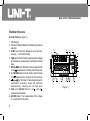
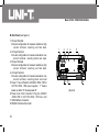
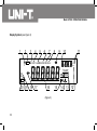
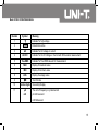
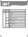
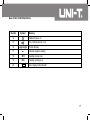
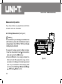
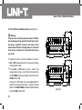
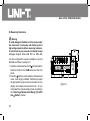
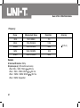
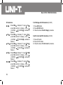
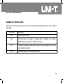
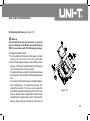
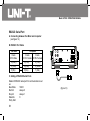
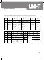
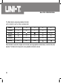
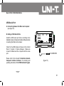
Model UT805
OPERATING MANUAL
Model UT805: OPERATING MANUAL
TABLE OF CONTENTS
TITLE
Overview
Unpacking Inspection
Safety Information
Rules For Safe Operation
International Electrical Symbols
The Meter Structure
A. Front Panel
B. Rear Panel
Functional Buttons
Display Symbols
Measurement Operation
A. DC Voltage Measurement
B. AC Voltage Measurement
C. DC or AC Current Measurement
D. Measuring Resistance
E. Testing Diodes
F. Testing for Continuity
G. Capacitance Measurement
H. Frequency Measurement
Selecting a Measurement Range ( , AUTO and
The Use of Relative Value Mode
MAX MIN Mode
The Use of STO and RCL Button
Operation of Hold Mode
General Specifications
Accuracy Specifications
A. DC Voltage
PAGE
Button)
3
4
5
5
7
8
8
10
11
14
18
18
20
22
24
27
29
31
33
35
36
37
38
39
39
41
41
1
Model UT805: OPERATING MANUAL
TITLE
B. AC Voltage
C. DC Current
D. AC Current
E. Resistance
F. Diode Test
G. Continuity Test
H. Capacitance
I. Frequency
Calibration Procedure
A. DC Voltage
B. AC Voltage
C. DC Current
D. AC Current
E. Resistance
F. AC Voltage with DC deviation (AC+DC)
G. AC Current with DC deviation (AC+DC)
Summary of error codes
Maintenance
A. General Service
B. Replacing the Fuses
RS232C and USB Serial Port
System Requirements for Installing the UT805 Interface Program
RS232C Serial Port
A. Connecting between the Meter and computer
B. RS232C Port Cable
C. Setting of RS232C Serial Ports
USB Serial Port
A. Connecting between the Meter and computer
B. Setting of USB Serial Ports
2
PAGE
42
43
44
45
46
46
47
48
49
49
50
51
51
52
52
52
53
54
54
55
57
57
58
58
58
58
61
61
61
Model UT805: OPERATING MANUAL
Overview
This Operating Manual covers information on safety
and cautions. Please read the relevant information
carefully and observe all the Warnings and Notes strictly.
Warning
To avoid electric shock or personal injury, read the
“Safety Information” and “Rules for Safety Operation”
carefully before using the Meter.
Model UT805 is a kind of 5 1/2 digit, vacuum-fluorescent,
dual display bench-type true RMS Multimeter (hereafter
referred to as “the Meter”). The Meter’s circuit design
is the combination of large scale integrated simulation
and digital circuit, taking microcomputer technology
with 24 counts A/D converter as a core, highly precise
amplifier, True RMS’s AC converter and full electronic
calibration technique to make it as a reliable and accurate
Multimeter.
In addition to all the conventional features including
DC/AC voltage, current, resistance, diode, continuity
test, capacitance, frequency, there is a recall function.
RS232C and USB standard serial port for easy
connection with computer to realize macro recording
and monitoring and capture of transient dynamic data,
displaying change of waveform during the measurement,
providing data and evidence to engineering technicians
for scientific research.
This is also a highly applied digital multimeter of good
performance with full overload protection. This Meter
uses AC power to make it becoming a better electrical
equipment.
3
Model UT805: OPERATING MANUAL
Unpacking Inspection
Carefully remove the Meter from its shipping container and check the following items carefully to see any missing
or damaged part:
Item
Description
1
Operating Manual
1 piece
2
Test Lead
1 pair
3
Alligator Clip
1 pair
4
Multi-Purpose Socket
1 piece
5
Line Cord (AC220V~50Hz, 15W or AC110V~50Hz, 15W)
1 piece
6
RS232C Interface Cable
1 piece
7
USB Interface Cable
1 piece
8
Installation Guide & Computer Interface Software (CD-ROM)
1 piece
In the event you find any missing or damage, please contact your dealer immediately.
4
Qty
Model UT805: OPERATING MANUAL
Safety Information
This Meter complies with the standards IEC61010: in
pollution degree 2, overvoltage category (CAT. I 1000V,
CAT II 600V) and double insulation.
CAT. III: Distribution level, fixed installation, with smaller
transient overvoltage than CAT. IV.
CAT IV: Primary supply level, overhead lines, cable
systems etc.
Use the Meter only as specified in this operating manual,
otherwise the protection provided by the Meter may be
impaired.
In this manual, a Warning identifies conditions and
actions that pose hazards to the user, or may damage
the Meter or the equipment under test.
A Note identifies the information that user should pay
attention on.
Rules For Safe Operation
Warning
To avoid possible electric shock or personal injury,
and to avoid possible damage to the Meter or to the
equipment under test, adhere to the following rules:
l Before using the Meter inspect the case. Do not use
the Meter if it is damaged or the case (or part of the
case) is removed. Look for cracks or missing plastic.
Pay attention to the insulation around the connectors.
l Inspect the test leads and power cord for damaged
insulation or exposed metal. Check the test leads
for continuity. Replace damaged test leads and power
cord with identical model number or electrical
specifications before using the Meter.
l Inspect the VFD display for no display..
l Do not apply more than the rated voltage, as marked
on the Meter, between the terminals or between any
terminal and grounding.
International electrical symbols used on the Meter and
in this Operating Manual are explained on page 7.
5
Model UT805: OPERATING MANUAL
l Ensure the Meter is at right measurement position
range. Disconnect the connection between the test
lead and the circuit under tested before changing
over the range. No changeover of range shall be
made during measurement is conducted to prevent
damage of the Meter.
l When the Meter working at an effective voltage over
60V in DC or 30V in AC, special care should be taken
for there is danger of electric shock.
l Use the proper terminals, function, and range for your
measurements.
l Under the manual ranging mode, if the value to be
measured is unknown, use the maximum
measurement position and reduce the range step by
step until a satisfactory reading is obtained.
l Do not use or store the Meter in an environment of
high temperature, humidity, explosive, inflammable
and strong magnetic field. The performance of the
Meter may deteriorate after dampened.
l When using the test leads, keep your fingers behind
the finger guards.
6
l Disconnect circuit power and discharge all highvoltage capacitors before testing on-line resistance,
continuity, diodes, current, or capacitance.
l Before measuring current, check the Meter’s fuses
and turn off power to the circuit before connecting
the Meter to the circuit.
l Remove test leads, RS232C interface cable, USB
interface cable and alligator clip from the Meter and
turn the Meter power off before opening the Meter
case.
l When servicing the Meter, use only the same model
number or identical electrical specifications
replacement parts.
l The internal circuit of the Meter shall not be altered
at will to avoid damage of the Meter and any accident.
l Soft cloth and mild detergent should be used to clean
the surface of the Meter when servicing. No abrasive
and solvent should be used to prevent the surface of
the Meter from corrosion, damage and accident.
l The Meter is suitable for indoor use.
l Turn the Meter power off when it is not in use.
Model UT805: OPERATING MANUAL
International Electrical Symbols
AC or DC
Grounding
Double Insulated
Warning. Refer to the Operating Manual
High Voltage
Continuity Test
Diode
Capacitance Test
Fuse
Conforms to Standards of European Union
7
Model UT805: OPERATING MANUAL
The Meter Structure
A. Front Panel (see figure 1)
1. VFD Display
2. Primary Functional Buttons: Different key functions
selection.
3. COM Input Terminal: Negative input terminal,
inserting the black test lead.
4. V/ Input Terminal: Positive input terminal for voltage
and resistance measurement, inserting the red test
lead.
5. 200mA MAX Input Terminal: Positive input terminal
for mA measurement, inserting the red test lead.
6. 6. 10A MAX Input Terminal: Positive input terminal
for A measurement, inserting the red test lead.
7.
Input Terminal: Positive input terminal for
capacitance, frequency, diode and continuity
measurement, inserting the red test lead.
8. 2mA and 200mA Buttons: mA
and A
measurement selection
9. AC+DC Button: The measurement of AC voltage
or current with DC deviation.
8
1
2
3
4
5
6
12
11
10
9
(figure 1)
8
7
Model UT805: OPERATING MANUAL
10. CAL Button: Calibrate the accuracy of Voltage,
Current and Resistance
11. Secondary Functional Buttons: Different side
functions selection.
12. RANGE Button ( , AUTO and ): Select Auto or
Manual ranging
9
Model UT805: OPERATING MANUAL
B. Rear Panel (see figure 2)
1. HI Input Terminal:
l 4-wire configuration to measure resistance: high
current terminal, inserting red test lead.
2. LO Input Terminal
l 4-wire configuration to measure resistance: low
current terminal, inserting black test lead.
3. HI Input Terminal
l 4-wire configuration to measure resistance, high
current terminal, inserting red test lead.
4. LO Input Terminal
l 4-wire configuration to measure resistance, low
current terminal, inserting black test lead
5. Power: The on off switch of AC220V~50Hz, 15W or
AC110V~50Hz, 15W power supplier. “I” means
power up while “O” means power off.
6. Power-Line Cord Connector: Plug the AC220V
~50Hz,15W or AC110V~50Hz, 15W line cord
7. USB Interface Connector
8. RS232C Interface Connector
10
1
2
3
8
4
7
(figure 2)
5
6
Model UT805: OPERATING MANUAL
Functional Buttons
The pushbuttons on the front panel select the Meter functions and operations. Below table indicated for information
about the functional button operations.
Button
, AUTO and
Button)
Operation Performed
Switching between auto and manual ranging, step through the ranges when the Meter is at manual
ranging measurement mode.
Continuity Test
Diode Test
Frequency Test
Capacitance Test
Resistance Measurement:
l Press
to enter resistance measurement mode. Use the front input terminals for 2 wire
ACV
measurement and the back input terminals for 4 wire measurement.
AC Voltage Measurement, displaying True RMS value
DCV
DC Voltage Measurement
ACI
AC Current Measurement, displaying True RMS value
11
Model UT805: OPERATING MANUAL
Button
DCI
Operation Performed
AC Current Measurement
2mA &
l Press 2mA down to select 2mA current measurement range.
200mA
l Press 200mA down to select 200mA current measurement range.
l Press both 2mA and 200mA down is a mis-operation, the Meter displays “ --Err 1-“.
l When both 2mA and 200mA are not pressed down, 10A range is default when measuring current.
AC+DC
It is used to measure AC Voltage or Current with DC deviation:
l lt can only be used at AC Voltage or AC Current measurement mode otherwise the Meter displays
“--Err1-“, then back to the previous measurement range.
CAL
It is a calibration button:
l Press it to calibrate ACV, DCV, ACI, DCI, ACV and DCV with DC deviation, and resistance.
Details refer to page 52 of this operating manual.
REL
Press REL
to enter and exit REL mode.:
Press MAX MIN to select the maximum and minimum value.
12
Model UT805: OPERATING MANUAL
Button
Operation Performed
MAX MIN
Press MAX MIN to select the maximum and minimum value.
STO and
l Press STO to store the reading.
RCL
HOLD
l Press RCL to recall the stored reading.
HOLD has two features:
1. Data Holding
l Press HOLD to enter Hold mode, the VFD display
l Press HOLD again to exit Hold mode, the
2. Exit STO, RCL and MAX MIN mode.
disappear.
l Press HOLD to exit STO, RCL and MAX MIN mode when the Meter is at STO, RCL and MAX
MIN measurement mode.
13
Model UT805: OPERATING MANUAL
Display Symbols (see figure 3)
1
2
HOLD
3
4
5
6
7
8
9
10
11
µS
mS
kHz
AC+DC TrueRMS MAX MIN AVG
µmVAnF
STO
RCL
MK
WHz
14
13
AUTO
20 19
18 17
16
(figure 3)
14
15
12
Model UT805: OPERATING MANUAL
Number
Symbol
1
Meaning
Indicator for high voltage
2
HOLD
3
AC
4
AC+DC
5
True RMS
6
MAX
Display of maximum value
7
MIN
Display of minimum value
8
AVG
Display of average value
9
Data hold is active
Indicator for AC voltage or current
Indicator for AC AC Voltage or Current with DC deviation measurement
Indicator for True RMS value of AC measurement
Test of diode
10
Smaller digits
Secondary Display
11
µS
The unit of frequency in cycles/second:
mS
µS: Microsecond
mS: Millisecond
15
Model UT805: OPERATING MANUAL
Number
Symbol
Meaning
12
kHz
The unit of frequency of AC measurement: Kilohertz (shown in the secondary display)
13
nF
The unit of capacitance
µF
nF : Nanofarad
mF
µF : Microfarad
mF : Millifarad
mA
A
mV
V
A
: Amperes (amps). The unit of current.
mA : Milliamp
V
: Volts. The unit of voltage.
mV : Millivolt.
: Ohm. The unit of resistance.
16
k
k
: kilohm.
M
M
: Megaohm.
Model UT805: OPERATING MANUAL
Number
Symbol
Meaning
14
Relative mode is on
15
The continuity buzzer is on.
16
Larger digits
17
Primary Display
Indicates negative reading.
18
STO
Reading storage is on
19
RCL
Reading recalling is on
20
AUTO
Auto ranging mode indicator
17
Model UT805: OPERATING MANUAL
Measurement Operation
If you have not done so, plug the line cord into the
connector on the rear of the Meter.
A. DC Voltage Measurement (See figure 4)
RL
Warning
To avoid harms to you or damages to the Meter from
electric shock, please do not attempt to measure
voltages higher than 1000V or 750V rms although
readings may be obtained.
To measure DC voltage, connect the Meter as follows:
1. Insert the red test lead into the V/ terminal and the
black test lead into the COM terminal.
2. Press the DCV button. Auto ranging is default, the
Meter will select the appropriate range, and an
annunciator on the display will indicate measurement
units. Or you could select the manual ranging mode
according to the “Selecting a Measurement Range
( , AUTO and Button)” section.
18
COM
DCV
(figure 4)
Model UT805: OPERATING MANUAL
3. Connect the test leads across with the object being
measured as shown in figure 4. The measured value
shows on the primary display and the secondary
display shows the measuring range. The sampling
rate is around 2 times per second.
Note
l When the Meter is not zero in manual range mode,
you could short circuit the test lead and press REL
to zeroing to increase the accuracy.
l When DC voltage measurement has been completed,
disconnect the connection between the testing leads
and the circuit under test, and remove the testing
leads away from the input terminals of the Meter.
19
Model UT805: OPERATING MANUAL
B. AC Voltage Measurement (See figure 5)
Warning
To avoid harms to you or damages to the Meter from
electric shock, please do not attempt to measure
voltages higher than 1000V or 750V rms although
readings may be obtained.
Take extra care when measuring high voltage to avoid
electric shock.
To measure AC voltage, connect the Meter as follows:
1. Insert the red test lead into the V/ terminal and the
black test lead into the COM terminal.
2. Press ACV button, the Meter is ready for
measurement after around 8 seconds. Auto ranging
is default, the Meter will select the appropriate range,
and an annunciator on the display will indicate
measurement unit. Or you could select the manual
ranging mode according to the “Selecting a
Measurement Range ( , AUTO and Button)”
section.
20
RL
COM
ACV
(figure 5)
Model UT805: OPERATING MANUAL
3. Connect the test leads across with the object being
measured as shown in figure 5. The primary display
shows the True RMS AC value, the effective reading
is only applicable to the range of 10%~100%. The
measured signal frequency value shows on the
secondary display. The sampling rate is around 1
time per second.
4. To measure AC signal with DC deviation, first press
ACV button, then press AC+DC button. Otherwise,
the primary display shows “--Err 1-“, then back to
the present measurement range.
l When DC voltage measurement has been completed,
disconnect the connection between the testing leads
and the circuit under test, and remove the testing
leads away from the input terminals of the Meter.
Note
l When the input terminal is short circuit, it is allowed
to have maximum 500 digits of reading which does
not affect the accuracy.
l When the Meter is at auto ranging mode, the True
RMS transducer needs a longer time to stablize and
it requires to process AC signal frequency
measurement. Therefore it takes a longer time to
obtain a stable reading when changing from one
reading to a relatively large reading.
21
Model UT805: OPERATING MANUAL
C. DC or AC Current Measurement (see figure 6)
RL
Warning
If the fuse burns out during measurement, the Meter
may be damaged or the operator himself may be hurt.
Use proper terminals, function, and range for the
measurement. When the testing leads are connected
to the current terminals, do not parallel them across
any circuit.
COM
DCI
To measure current, connect the Meter as follows:
1. ACI or DCI measurement do not have auto ranging
measurement mode.
2. Press ACI or DCI button only to select 10A
measurement range. Insert the red test lead into
the 10A MAX terminal and black test lead into the
COM terminal. OR
Press ACI or DCI button, then press 2mA button to
select 2mA measurement range. Insert the red test
lead into the 200mA MAX terminal and black test lead
into the COM terminal. OR
22
RL
COM
ACI
(figure 6)
Model UT805: OPERATING MANUAL
3.
4.
5.
6.
7.
Press ACI or DCI button, then press 200mA button
to select 200mA measurement range. Insert the red
test lead into the 200mA MAX terminal and black
test lead into the COM terminal.
It is invalid to press down both 2mA and 200mA
button together.\
Connect the test lead in serial with the object being
measured. The measured value shows on the
primary display.
The ACI effective measurement reading is only
applicable to the range of 10%~100%.
In the DCI measurement mode, the secondary display
indicates the range.
In the ACI measurement mode, the secondary display
indicates the frequency value of the measured signal.
To measure AC current with DC deviation, first press
ACI button, then press AC+DC button. Otherwise,
the primary display shows “--Err 1-“, then back to
the present measurement range.
Note
l If the value of current to be measured is unknown,
use the maximum measurement position, and reduce
the range step by step until a satisfactory reading is
obtained.
l For safety sake, each measurement time of high
current (>5A) should be less than 10 seconds and
the interval time between 2 measurements should
be greater than 15 minutes.
l When the input of AC current measurement is open
circuit, it is allowed to have less than 500 digits of
reading which does not affect the accuracy.
l The AC current True RMS measurement takes a
longer time to stablize, and the Meter requires to
measure the frequency of AC current. Therefore it
is normal to take a longer time to obtain a stable
reading when changing from one reading to a relatively
large reading.
When current measurement has been completed,
disconnect the connection between the testing leads
and the circuit under test, and remove the testing
leads away from the input terminals of the Meter.
23
Model UT805: OPERATING MANUAL
D. Measuring Resistance
Warning
To avoid damages to the Meter or to the devices under
test, disconnect circuit power and discharge all the
high-voltage capacitors before measuring resistance.
To avoid harms to you, please do not attempt to input
voltages higher than 60V DC or 30V AC.
Two wire configuration measure resistance, connect
the Meter as follows: (see figure 7)
1. Insert the red test lead into the V/ terminal and the
black test lead into the COM terminal at the front
panel.
2. Press the button to enter resistance measurement
mode. Auto ranging is default, the Meter will select
the appropriate range, and an annunciator on the
display will indicate measurement units. Or you
could select the manual ranging mode according to
the “Selecting a Measurement Range ( , AUTO
and Button)” section.
24
(figure 7)
Model UT805: OPERATING MANUAL
3. To obtain more accurate readings, you could shortcircuit the test lead and press REL to display “0”
before carrying out measurement
4. Connect the test leads across with the object. The
measured value shows on the primary display and
the measuring range shows on the secondary display.
Four wire configuration measure resistance, connect
the Meter as follows: (see figure 8)
1. Use 2 sets of test lead and insert them into the rear
panel of the Meter.
2. Insert two red test leads into the two red terminals
at the rear panel.
3. Insert two black test leads into the two black terminals
at the rear panel
4. Short circuit the four test laads and press REL to
display “0”.
5. Connect the test leads across with the object. The
measured value shows on the primary display and
the measuring range shows on the secondary display.
6. Four wire configuration measuring resistance can
eliminate the influence of the test lead internal
resistance, it is suitable for testing small resistance.
Rx
HI
L
R
L0
(figure 8)
25
Model UT805: OPERATING MANUAL
Note
l When measuring high resistance (>1M ), it is normal
to take several seconds to obtain a stable reading.
In order to obtain stable reading, choose shorter test
lead to carrying out measurement.
l The LCD displays OL indicating open-circuit for the
tested resistor or the resistor value is higher than
the maximum range of the Meter.
l When resistance measurement has been completed,
disconnect the connection between the testing leads
and the circuit under test, and remove the testing
leads away from the input terminals of the Meter.
26
Model UT805: OPERATING MANUAL
E. Testing Diodes (See figure 9)
Warning
To avoid possible damage to the Meter and to the
device under test, disconnect circuit power and
discharge all high-voltage capacitors before testing
diodes.
To avoid harms to you, please do not attempt to input
voltages higher than 60V DC or 30V AC.
COM
Use the diode test to check diodes, transistors, and
other semiconductor devices. The diode test sends a
current through the semiconductor junction, and then
measures the voltage drop across the junction. A good
silicon junction drops between 0.5V and 0.8V.
To test a diode out of a circuit, connect the Meter as
follows:
1. Insert the red test lead into
terminal and
the black test lead into the COM terminal.
2. Press
button to enter diode measurement mode.
3. For forward voltage drop readings on any
semiconductor component, place the red test lead
(figure 9)
27
Model UT805: OPERATING MANUAL
on the component’s anode and place the black test
lead on the component’s cathode.
4. The measured value shows on the primary display
and the secondary display shows 6.000V range.
Note
l Connect the test leads to the proper terminals as
said above to avoid error display. The primary display
shows OL indicating diode being tested is open or
polarity is reversed. The unit of diode is Volt (V),
displaying the forward voltage drop readings.
l Open circuit voltage is around 2.8V.
l When diode testing has been completed, disconnect
the connection between the testing leads and the
circuit under test, and remove the testing leads away
from the input terminals of the Meter.
28
Model UT805: OPERATING MANUAL
F. Testing for Continuity (See figure 10)
Warning
To avoid damages to the Meter or to the devices under
test, disconnect circuit power and discharge all the
high-voltage capacitors before testing for continuity.
To avoid harms to you, please do not attempt to input
voltages higher than 60V DC or 30V AC.
To test for continuity, connect the Meter as below:
1. Insert the red test lead into the
terminal
and the black test lead into the COM terminal.
2. Press
button to enter continuity measurement
mode.
3. Connect the test lead across with the object being
measured.
The buzzer sounds if the resistance of a circuit under
test is < 25 , the circuit is in good condition. The
primary display shows the reading of the tested
resistor and the secondary displays shows 600.0
range.
Rx
COM
(figure 10)
29
Model UT805: OPERATING MANUAL
Note
l Open circuit voltage around 1.2V.
l The primary display shows OL indicating the tested
circuit is open.
l When continuity testing has been completed,
disconnect the connection between the testing leads
and the circuit under test, and remove the testing
leads away from the input terminals of the Meter.
30
Model UT805: OPERATING MANUAL
G. Capacitance Measurement (See figure 11)
Warning
To avoid damage to the Meter or to the equipment
under test, disconnect circuit power and discharge
all high-voltage capacitors before measuring
capacitance. Use the DC Voltage function to confirm
that the capacitor is discharged.
To avoid harms to you, please do not attempt to input
voltages higher than 60V DC or 30V AC.
To measure capacitance, connect the Meter as follows:
1. Insert the red test lead into the
terminal
and the black test lead into the COM terminal.
2. Press
button to select capacitance measurement
mode. Auto ranging is default.
3. Connect the test lead across with the object being
measured. For the capacitor lead is less than 0.6mm,
It is recommended to use the multi-purpose socket
to proceed the measurement as the above figure 11.
It is more suitable for testing small capacitor, it can
reduce the influence of distributed capacitor,
COM
(figure 11)
31
Model UT805: OPERATING MANUAL
4. The measured value shows on the primary display.
The secondary display shows the measuring range
Note
l If the tested capacitance has polarity, connect the
red test lead to the capacitor’s positive and the black
test lead to the capacitor’s negative.
l When the Meter is in open circuit and manual ranging
mode, press REL to display “0”.
l In the manual range mode, press
to up range or
down range to the desired range.
button cannot
be used
l It is normal to take a longer time when testing a
capacitor value higher than 10 F.
l The Meter display shows OL indicating the tested
capacitor is shorted or it exceeds the maximum range.
l When capacitance measurement has been
completed, disconnect the connection between the
testing leads and the circuit under test and remove
the testing leads away from the input terminals of
the Meter.
32
Model UT805: OPERATING MANUAL
H. Frequency Measurement (see figure 12)
Warning
To avoid harms to you, please do not attempt to input
voltages higher than 60V DC or 30V AC.
To measure frequency, connect the Meter as follows:
1. Insert the red test lead into the
terminal
and the black test lead into the COM terminal.
2. Press Hz button to select frequency measurement
mode. Auto ranging is default.
3. Connect the test leads across with the object being
measured.
The measured value shows on the primary display
and the secondary display shows the cycle of the
tested frequency.
COM
Hz
Hz
(figure 12)
33
Model UT805: OPERATING MANUAL
Note
l When making frequency measurement, it must comply
with the following scope (a) requirement:
When 10Hz ~ 1Mz
: 150mV a 30V rms.
When > 1Mz~ 10MHz : 300mV a 30V rms
When > 10Mz~ 50MHz : 600mV a 30V rms
When > 50Mz
: Unspecified
l In the manual range mode, press
to up range or
down range to the desired range.
button cannot
be used
l When frequency measurement has been completed,
disconnect the connection between the testing leads
and the circuit under test, and remove the testing
leads away from the input terminals of the Meter.
34
Model UT805: OPERATING MANUAL
Selecting a Measurement Range ( , AUTO and
Button)
The Meter is default at DC Voltage 2V auto ranging
measurement mode when turning on the Meter.
Measurement ranges can be selected automatically by
the Meter in autorange or manually by the user. In the
autorange mode, the Meter selects the appropriate
range for the measurement reading.
The use of the buttons of
, AUTO and
:
l Press
or button to enter the previous range of
the auto ranging measurement mode.
l To switch between measuring functions at manual
ranging mode, the Meter will enter auto ranging mode
automatically unless the measuring functions has
only manual ranging mode. When you are in
autoranging mode, the AUTO annunciator is lit.
l In manual range, the Meter remains in the selected
range regardless of input. Press AUTO to toggle
back to autoranging.
l At resistance measurement mode:
Auto ranging measurement mode is default.
Press AUTO to toggle in and out of the manual
ranging mode, or press
or to toggle in the
manual ranging mode.
In the manual range mode, press
or to up
range or down range to the desired range.
l At ACV and DCV measurement mode:\
Auto ranging measurement mode is default.
Press AUTO to toggle in and out of the manual
ranging mode, or press
or to toggle in the
manual ranging mode.
In the manual range mode, press
or to up
range or down range to the desired range.
At 200mV range, the Meter does not have auto
ranging measurement mode.
l At capacitance and frequency measurement mode:
Auto ranging measurement mode is default.
Press AUTO to toggle in and out of the manual
ranging mode, or press to toggle in the manual
ranging mode.
In the manual range mode, press to up range
or down range to the desired range.
cannot be used.
l At diode, continuity, ACI and DCI measurement mode,
both
and cannot be used.
35
Model UT805: OPERATING MANUAL
The Use of Relative Value Mode
Relative Mode applies to all functions except continuity,
diode and frequency measurements.
When the relative mode is selected, the reading on the
primary display is always the difference between the
relative base and the input measurement. For example,
if the relative base is 15.0000V, and the present reading
is 14.1000V, the display will show -00.9000.
Press REL to toggle in and out of the relative mode.
When the relative mode is selected: the lsat valid reading
is stored as the relative base, the primary display zeros
out and display “0”,
is shown on the primary display.
(The secondary display is unaffected.)
Selecting the relative mode turns off autoranging and
locks in the present range. Make sure you are in the
correct range before selecting the relative mode. If you
press
or after the relative mode has been selected,
you will automatically exit .
36
AUTO cannot be pressed, otherwise “--Err 1-“ will be
displayed and then back to the current meaurement
range
To enter or eixt REL mode:
l Press REL to enter REL mode, the Meter displays
, auto ranging turns off, and the present meauremnet
range is locked and stored the present measurement
value as the stored value, the Meter displays “0”.
The present measurement value obtained later on is
the difference of the stored value.
l Press REL again to exit REL mode.
l Press REL again to step the display through the
above sequence.
Model UT805: OPERATING MANUAL
MAX MIN Mode
MAX MIN mode applies only to DCV, ACV, ACV and
ACI with DC deviation, and resistance. Press MAX
MIN when the Meter is at other measurements mode,
the Meter displays “--Err 1-“ and then back to the current
measurement mode.
The MAX MIN mode causes the Meter to store minimum
and maximum inputs measured since the MAX MIN
was selected.
Press MAX MIN to select the MAX MIN mode. When
the MAX MIN is first selected, the maximum and minijum
values are set to the displayed reading and the MAX
annunciator lights. Press MAX MIN again to display
the minimum reading (and the MIN annunciator lights.)
Each subsequent press of the MAX MIN button toggles
between the maximum and minimum measurements
taken. To exit MAX MIN mode, press HOLD button..
Selecting the MAX MIN mode turns off autoranging and
locks in the present range. Make sure you are in the
correct range before selecting the MAX MIN mode. If
you press
or after MAX MIN has been selected,
you will automatically exit the MAX MIN mode.
Measurement speed is 100 times / second. The display
flashes “OL” when the testing exceeds the measurement
speed.
MAX MIN mode and REL mode cannot be used together.
The Meter displays “--Err 1-“ and then back to the
current measurement mode if REL is pressed under
MAX MIN mode.
37
Model UT805: OPERATING MANUAL
The Use of STO and RCL Button
STO Button
l Press STO to step through 7 different storage speed
including r=0, r=1, r=2, r=3, r=4, r=5 and r=6, they will
be shown on the secondary display.
l r=0 means store each reading per each sampling.
r=1 means store each reading per 10 times sampling
r=2 means store each reading per 100 times sampling
r=3 means store each reading per 500 times sampling
r=4 means store each reading per 1000 times sampling
r=5 means store each reading per 5000 times sampling
r=6 means manual storage. You need to press STO
for each reading storage.
l The maximum pieces of stored reading is 100. “RCL”
will be flicking on the VFD when the stored value is
over 100pcs. You need then need to recall the reading,
l Press HOLD to exit STO mode.
38
l Follow the following procedure to recall the stored
reading:
1. Press HOLD to exit STO mode.
2. Press RCL to step through MAX reading, MIN
reading, AVG reading, the first stored reading
(n=00), the second stored reading (n=02) until
the 100st stored reading (n=99) in sequence.
3. Press HOLD to exit RCL mode.
l When recalling the stored reading, the Meter must be
at the stored reading measurement ranges, otherwise
it will display “--Err 3 –“, then back to new measurement
ranges.l When the Meter is at STO mode, pressing RCL two
times to display through MAX reading, MIN reading,
AVG reading and the present measurement reading
in sequence. Reading storage is unaffected.
Model UT805: OPERATING MANUAL
Operation of Hold Mode
General Specifications
The Hold mode allows you to take a measurement and
hold that measurement on the display. This feature
can be particularly advantageous in difficult or hazardous
circumstances when you might want to keep your eyes
fixed on the probes, and then read the display when it
is safe or convenient to do so. When a new, stable
reading is detected, the display is automatically updated.
l Maximum Voltage between any Terminals and
Grounding:
Refer to different range input protection voltage.
Fused Protection for 200mA Input Terminal:
l
315mA, 250V, fast type, 5x20mm.
Fused Protection for 10A Input Terminal:
l
10A, 250V, fast type, 5x20mm.
l
Fused Protection for AC220V Terminal:
315mA, 250V, fast type, 5x20mm.
Maximum
Display:
l
Main LCD Display : 220000,
Small LCD Display: 9999, VFD
Measuring
Theory:
l
- type, A/D converter
l Measurement Speed:
Updates around 2 times/second. At max/min mode,
updates 100 times/second
Range:
l
Manual or auto ranging.
Press HOLD to select Hold mode. When hold mode
is selected, is shown in the primary display. The
current reading on the display is hold. To exit hold
mode, press HOLD again,
will be disappeared.
You can also press HOLD to exit STO, RCL and MAX
MIN mode when the Meter is at STO, RCL and MAX
MIN measurement mode.
39
Model UT805: OPERATING MANUAL
l Icon Display:
Equipped with functions and electrical unit symbol
icon display.
l Polarity Display: Auto
l Overloading Display: OL
l Temperature:
Operating: 0 0 C to +40 0 C (32 0 F to +104 0 F).
Storage : -100C to +500C (140F to +1220F).
l Relative Humidity:
75% @ 00C - 300C below; 50% @ 300C - 400C.
l Altitude:
Operating: 2000 m.
Storage : 10000 m.
l Power:
AC220V~50Hz, 15W or AC110V~50Hz, 15W
l Dimensions (HxWxL):
240 x 105 x 370 mm.
l Weight:
Approximate 2.9kg (accessories: 0.4kg).
40
l Safety/Compliances:
IEC61010 CAT.I 1000V, CAT.II 600V overvoltage
and double insulation standard.
l Certifications:
UL pending.
Model UT805: OPERATING MANUAL
Accuracy Specifications
Accuracy: (a% reading + b digits), guarantee for 1 year. Operating temperature: 230C 50C.
Relative humidity: not more than 75% RH. Temperature coefficient: 0.1 x (specified accuracy)/10C.
Note
l UT805 multimeter is a precise digital multimeter when you turn on the UT805 allow a warm-up period of at least
30 minutes for the internal components to stabilize this ensures that the multimeter accord with the specification
A. DC Voltage
Range
Measurement Scope
Resolution
Accuracy
200mV
1 V~220.000mV
1 V
In REL mode:
2V
10 V~2.20000V
10 V
(0.006%+2)
20V
100 V~22.0000V
100 V
200V
1mV~220.000V
1mV
1000V
10mV~1000.00V
10mV
(0.007%+2)
Remarks:
l Overload Protection: 1000V DC or 750V AC
l Input Impedance:
At 200mV and 2V ranges: more than 500M
At 20V, 200V and 1000V ranges: Around 10M
41
Model UT805: OPERATING MANUAL
B. AC Voltage (True RMS)
Range
Accuracy
Resolution
40Hz~10kHz
200mV
1 V
2V
10 V
20V
100 V
200V
1mV
750V
10mV
(0.1%+100)
(0.2%+200)
(0.2%+100)
(0.3%+200)
40Hz-1kHz:
>1kHz-5kHz:
(0.3%+100)
Remarks:
l Overload Protection: 1000V DC or 750V AC
l Input Impedance:10M
l AC+DC Tolerance Limit: Same as AC + 1%
l Displays:
The effective reading is only applicable to the range
The full range of each measurement range displays
42
>10~30kHz
(0.4%+100)
>30~50kHz
>50~100kHz
(0.3%+200)
(0.5%+300)
(1%+500)
(2%+500)
N/A
N/A
N/A
N/A
of 10%~100%.
220000 except at AC750V measurement range.
Model UT805: OPERATING MANUAL
C. DC Current
Range
Measurement Scope
Resolution
2mA
0.01 A~2.20000mA
0.01 A
20mA
1 A~220.000mA
1 A
10A
0.1mA~10.0000A
0.1mA
Accuracy
(0.03%+10)
(0.8%+60)
Remarks:
l Overload Protection:
At mA Range: Fuse 315mA, 250V, fast type, 5x20mm.
At A Range :Fuse 10A, 250V, fast type, 5x20mm.
l At 5A range :Continuous measurement is allowed.
l At >5A range:For continuous measurement 10 seconds and interval not less than 15 minutes.
43
Model UT805: OPERATING MANUAL
D. AC Current (Frequency range: 40Hz~5kHz)
Range
Measurement Scope
Resolution
2mA
0.01 A~2.20000mA
0.01 A
20mA
1 A~220.000mA
1 A
10A
0.1mA~10.0000A
0.1mA
Accuracy
(0.3%+100)
(2%+200)
Remarks:
l Overload Protection:
At mA Range:Fuse 315mA, 250V, fast type, 5x20mm.
At A Range :Fuse 10A, 250V, fast type, 5x20mm.
l At 5A range: Continuous measurement is allowed.
l At >5A range: For continuous measurement 10 seconds and interval not less than 15 minutes.
l Displays
: The effective reading is only applicable to the range of 10%~100%.
l AC+DC Tolerance Limit: Same as AC + 1%.
44
Model UT805: OPERATING MANUAL
E. Resistance
Range
Measurement Scope
Resolution
Accuracy
2k
0.01 ~2.20000k
0.01
In REL mode: (0.01%+8)
20k
0.1 ~22.0000k
0.1
In REL mode:
200k
1 ~220.000k
1
(0.01%+5)
2M
10 ~2.20000M
10
(0.02%+10)
20M
100 ~22.0000M
100
(0.1%+20)
Remarks:
l Overload Protection : 1000V DC or 750V AC
l Open Circuit Voltage:Around 2V
45
Model UT805: OPERATING MANUAL
F. Diode Test
Range
Measurement Scope Resolution
Overload Protection
Remarks
l Open circuit voltage approximate 2.8V.
0.00~6.00V
10mV
250Vp
l A good silicon junction drops between
0.5V and 0.8V
G. Continuity Test
Range
Measurement Scope Resolution
Overload Protection
Remarks
l Open circuit voltage approximate -1.2V.
l When circuit disconnected with
0~600
1
250Vp
resistance value 50 , buzzer does
not beep.
l When circuit is in good connection with
resistance value 10 , buzzer beeps
continuously.
46
Model UT805: OPERATING MANUAL
H. Capacitance
Range
Measurement Scope
Resolution
Accuracy
6nF
1pF~5.999nF
1pF
In REL mode: (2.5%+5)
60nF
10pF~59.99nF
10pF
In REL mode: (2.0%+5)
600nF
100pF~599.9nF
100pF
6 F
1nF~5.999 F
1nF
60 F
10nF~59.99 F
10nF
600 F
100nF~599.9 F
100nF
(5.0%+5)
6mF
1 F~5.999mF
1 F
Un-Specified
(2.0%+5)
Remarks:
l Overload Protection: 250Vp
47
Model UT805: OPERATING MANUAL
I. Frequency
Range
Measurement Scope
6kHz
1Hz~5.999kHz
1Hz
60kHz
10Hz~59.99kHz
10Hz
600kHz
100Hz~599.9kHz
100Hz
6MHz
1kHz~5.999MHz
1kHz
60MHz
10kHz~59.99MHz
10kHz
Remarks:
l Overload Protection: 250Vp
l Input scope (a): (DC electric level is zero)
When 10Hz ~ 1MHz: 150mV a 30V rms
When > 1MHz ~ 10MHz: 300mV a 30V rms
When > 10MHz ~ 50MHz: 600mV a 30V rms
When > 50MHz: Unspecified
48
Resolution
Accuracy
(0.1%+3)
Model UT805: OPERATING MANUAL
CALIBRATION PROCEDURE
l The calibration must be done in manual ranging
mode.
l Power-up the Meter and allow it to stabilize for one
hour.
l The accuracy of the original source must be 1/3 better
than the calibrated range
A. DC Voltage (Calibrate both positive and negative
polarity)
200mV: Short circuit the test lead, press REL
to
display “0”, input 190mV, then press CAL
button.
The Meter displays: (--CAL--)
(-HI-END)
(190.000mV), calibration finished.
2V
: Short circuit the test lead, press REL to
display “0”, input 1.9V, then press CAL
button.
The Meter displays: (--CAL--)
(-HI-END)
(1.90000V), calibration finished.
20V
: Short circuit the test lead, press REL to
display “0”, input 19V, then press CAL
button.
The Meter displays: (--CAL--)
(-HI-END)
(19.0000V), calibration finished.
200V : Short circuit the test lead, press REL to
display “0”, input 190V, then press CAL
button.
The Meter displays: (--CAL--)
(-HI-END)
(190.000V), calibration finished
1000V : Short circuit the test lead, press REL to
display “0”, input 1000V, then press CAL
button.
The Meter displays: (--CAL--)
(-HI-END)
(1000.00V), calibration finished
49
Model UT805: OPERATING MANUAL
B. AC Voltage(750V range: frequency 1kHz, all other
ranges: frequency 20kHz)
200mV: Input 19mV, press CAL button to display
(-- CAL--) (-LO-END)
(
) Input
190mV, press CAL button to display (--CAL--)
(-HI-END)
(190.000mV),
calibration finished
2V
: Input 190mV, press CAL button to display
(--CAL--) (-LO-END) (
) Input
1.9V, press CAL button to display (-- CAL--)
(-HI-END)
(1.90000V), calibration
finished.
20V : Input 1.9V, press CAL button to display
(-- CAL--) (-LO-END)
(
) Input
19V, press CAL button to display (-- CAL--)
(-HI-END)
(19.0000V), calibration
finished.
200V : Input 19V, press CAL button to display
(--CAL--) (-LO-END)
(
) Input
190V, press CAL button to display (-- CAL--)
(-HI-END)
(190.000V), calibration
finished.
50
750V
: Input 190V, press CAL button to display
(-- CAL--) (-LO-END) (
) Input
750V, press CAL button to display (-- CAL--)
(-HI-END)
(750.00V), calibration
finished.
AC+DC: Carry out the calibration according to each
range of DC voltage.
Model UT805: OPERATING MANUAL
C. DC Current (Calibrate both positive and negative
polarity)
2mA
: Press REL to display “0”, input 1.9mA,
press CAL button to display (--CAL--)
(-HI-END)
( 1.90000mA), calibration
finished.
200mA : Press REL to display “0”, input 190mA,
press CAL button to display (--CAL--)
(-HI-END)
( 190.000mA), calibration
finished
10A
: Press REL to display “0”, input 10A,
press CAL button to display (--CAL--)
(-HI-END)
( 10.0000A), calibration
finished
D. AC Current (Frequency: 1kHz)
2mA
: Input 0.19mA, Press CAL button to display
(--CAL--) (-LO-END) (
) Input
1.9mA, Press CAL button to display (--CAL--)
(-HI-END)
(1.90000mA), calibration
finish.
200mA : Input 19mA, Press CAL button to display
(--CAL--) (-LO-END) (
) Input
190mA, Press CAL button to display
(--CAL--)
(-HI-END)
(190.000mA),
calibration finish
10A
: Input 1.9A, Press CAL button to display
(-- CAL--) (-LO-END) (
) Input
10A, Press CAL button to display
(-- CAL--)
(-HI-END)
(10.0000A),
calibration finish
AC+DC: AC+DC:Carry out the calibration according
to each range of DC current.
51
Model UT805: OPERATING MANUAL
E. Resistance
: Press REL
press CAL
(-HI-END)
finished.
20k : Press REL
press CAL
(-HI-END)
finished.
200k : Press REL
press CAL
(-HI-END)
finished.
2M
: Press REL
press CAL
(-HI-END)
finished.
20M : Press REL
press CAL
(-HI-END)
finished
2k
52
F. AC Voltage with DC deviation (AC+DC)
to display “0”, input 1.9k ,
button to display (--CAL--)
( 1.90000k ), calibration
to display “0”, input 19k ,
button to display (--CAL--)
( 19.0000k ), calibration
to display “0”, input 190k ,
button to display (--CAL--)
( 190.000k ), calibration
to display “0”, input 1.9M ,
button to display (--CAL--)
( 1.90000M ), calibration
to display “0”, input 19M ,
button to display (--CAL--)
( 19.0000M ), calibration
1. Press ACV button
2. Press AC+DC button
3. Follow the above “B. AC Voltage” procedure
G. AC Current with DC deviation (AC+DC)
1. Press ACI button
2. Press AC+DC button
3. Follow the above “D. AC Current” procedure.
Model UT805: OPERATING MANUAL
SUMMARY OF ERROR CODES
If the Meter is failed to operate properly, an error code is displayed in the primary display. Error codes are listed in
below table:
Error Code
Description
Err1
Wrong button is pressed
Err2
At AVG mode, the number of average times > 999998, out of range.
At REL mode, the stored value > 220000, out of range.
Err3
The present measurement range and the range of the stored reading is not the same
when recalling the reading
Err4
The tested reading is out of the calibration scope
53
Model UT805: OPERATING MANUAL
Maintenance
A. General Service
This section provides basic maintenance information
including general service and fuse replacement
instruction.
l Calibrate the Meter around once a year to ensure the
accuracy of each functions.
l Periodically wipe the case with a damp cloth and mild
detergent. Do not use abrasives or solvents.
l To clean the terminals with cotton bar with detergent,
as dirt or moisture in the terminals can affect readings.
l Turn off the power of the Meter when it is not in use.
l Do not use or store the Meter in a place of humidity,
high temperature, explosive, inflammable and strong
magnetic field.
Warning
Do not attempt to repair or service your Meter unless
you are qualified to do so and have the relevant
calibration, performance test, and service information.
To avoid electrical shock or damage to the Meter, do
you get water inside the case.
54
Model UT805: OPERATING MANUAL
B. Replacing the Fuses (see figure 13)
Warning
To avoid electrical shock or arc blast, or personal
injury or damage to the Meter, use specified fuses
ONLY in accordance with the following procedure.
To replace the Meter’s fuse:
1. Turn the Meter off, disconnect the power cord and
remove all connections from the terminals.
2. Fuse 1:The line power fuse is in series with the power
supplier. This fuse is located at the top of the power
-line cord connector on the rear panel.
To replace this fuse, unplug the line cord and remove
the line power fuse housing to install the replacement
fuse.
Fuse 2 and 3:These two fuses are located inside the
fuse compartment. To replace these fuses, first
unplug the line cord. Then use a coin to open the
accessories compartment at the top of the front cover,
then you will see a fuse compartment. Open the fuse
compartment to replace fuse 2 and 3. Remove the
fuse by gently prying one end loose, then take out
(figure 13)
55
Model UT805: OPERATING MANUAL
the fuse from its bracket. Then install the
replacement fuse.
3. Install ONLY replacement fuses with the identical
type and specification as follows and make sure the
fuse is fixed firmly in the bracket.
Fuse 1: 315mA, 250V, fast type, 5x20mm (AC220V)
Fuse 2: 315mA, 250V, fast type, 5x20 mm (mA)
Fuse 3: 10A, 250V, fast type, 5x20 mm (A)
Replacement of the fuses is seldom required. Burning
of a fuse always results from improper operation.
56
Model UT805: OPERATING MANUAL
RS232C and USB Serial Port
System Requirements for Installing the UT805
Interface Program
To use UT805 Interface Program, you need the
following hardware and software:
l An IBM PC or equivalent computer with 80486 or
higher processor and 600 x 800 pixel or better monitor.
l Microsoft Windows 95 or above.
l At least 8MB of RAM.
l At least 8MB free space in hard drive.
l Can access to a local or a network CD-ROM.
l A free serial port.
l A mouse or other pointing device supported by
Windows.
57
Model UT805: OPERATING MANUAL
RS232C Serial Port
A. Connecting between the Meter and computer
(see figure 14)
B. RS232C Port Cable
The Meter
D-sub
9 Pin Male
2 (RXD)
3 (TXD)
5 (SG)
Computer
D-sub
D-sub
9 Pin Female 25 Pin Female
3 (TXD)
2 (TXD)
2 (RXD)
3 (RXD)
5 (SG)
7 (SG)
C. Setting of RS232C Serial Ports
Default of RS232C serial port for communication is set
as:
Baud Rate
19200
Start bit
always 0
Stop bit
always 1
Data bits
8
Parity Odd
58
(figure 14)
Model UT805: OPERATING MANUAL
Serial port output 25 bits. Each bit is an alphabet, below table explains the meaning of each alphabet:
Number
1
2
3
1
2
3
4
5
$
Start
Character
S (STO)
R (RCL)
D (STO+RCL)
H (HOLD
X (MAX)
N (MIN)
G (AVG)
Number
8-14
15
1
2
3
4
5
6 Digit + dp
k
M
m
n
16
V
A
F
0( )
H (Hz)
4
5
C (Continuity) E (REL)
D (Diode)
U (AUTO)
A (AC)
(AC+DC)
17-21
4 Digit + dp
22
k (kHz)
m (mS)
( S)
23
#
End
Character
6
7
!
High
Voltage
+
C
E
24
CR
25
LF
59
Model UT805: OPERATING MANUAL
The Meter adopts a single large alphabet command,
each command is sent out twice as below table:
Number
Command
Meaning
Number
Command
Meaning
1
A
DCI
10
J
ACV
2
B
3
C
11
K
REL
12
L
HOLD
4
D
ACI
13
M
5
E
AC+DC
14
N
When the Meter receives the computer sent command, same large alphabet command twice, it will return the same
alphabet. The Meter will not response if a wrong alphabet command is received.
60
Model UT805: OPERATING MANUAL
USB Serial Port
A. Connecting between the Meter and computer
(see figure 15)
B. Setting of USB Serial Ports
Install the USB serial port driver according to the
Installation Guide & Computer Interface Software before
connecting the Meter and computer.
Check for the USB Serial port shown at the Control
Panel => System => Device Manager. Make sure
connect the Meter and the computer with the same
port.
Please refer to the included “Installation Guide &
Computer Interface Software” for installing and
operating instructions of the UT805 Interface Program.
TO COMPUTER
(figure 15)
**END**
61
Model UT805: OPERATING MANUAL
This operating manual is subject to change without notice.
C Copyright 2005 Uni-Trend International Limited.
All rights reserved.
Manufacturer: UNI-TREND TECHNOLOGY(DONG GUAN)LIMITED
Address: Dong Fang Da Dao, Bei Shan Dong Fang Industrial
Development District, Hu Men Town, Dong Guan City,
Guang Dong Province, China
Headquarters: Uni-Trend International Limited
Address: Rm901, 9/F, Nanyang Plaza 57 Hung To Road
Kwun Tong Kowloon, Hong Kong
Tel: (852) 2950 9168
Fax: (852) 2950 9303
Email: [email protected]
http://www.uni-trend.com
62