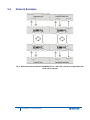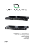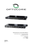
1
PG2-MADI-F-FX User Guide PN: 399G089 Rev A 05/19/14 Document Reference Clear-Com PG2-MADI-F-FX User Guide Part Number: 399G089 Revision: A Legal Disclaimers Copyright © 2014 HME Clear-Com Ltd. All rights reserved. Clear-Com and the Clear-Com logo are registered trademarks of HM Electronics, Inc. The software described in this document is furnished under a license agreement and may be used only in accordance with the terms of the agreement. The product described in this document is distributed under licenses restricting its use, copying, distribution, and decompilation/reverse engineering. No part of this document may be reproduced in any form by any means without prior written authorization of Clear-Com, an HME Company. Clear-Com Offices are located in California, USA; Cambridge, UK; Dubai, UAE; Montreal, Canada; and Beijing, China. Specific addresses and contact information can be found on Clear-Com’s corporate website: www.clearcom.com Clear-Com Contacts Americas and Asia-Pacific Headquarters California, United States Tel: +1.510.337.6600 Email: [email protected] Europe, Middle East, and Africa Headquarters Cambridge, United Kingdom Tel: +44 1223 815000 Email: [email protected] Canada Office Quebec , Canada Tel: +1 (450) 653-9669 China Office Beijing Representative Office Beijing, P.R.China Tel: +8610 65811360 / 65815577 2 PG2-MADI-F-FX User Guide Contents Document Reference......................................................................................................... 2 1 Important Safety instructions ....................................................................... 5 1.1 Safety symbols ................................................................................................ 6 2 Device Description ........................................................................................ 7 3 Front Panel .................................................................................................... 9 4 Rear Panel ................................................................................................... 11 5 Device Details .............................................................................................. 12 5.1 Fiber Optic Connection.................................................................................. 12 5.2 MADI Ports.................................................................................................... 12 5.3 SANE Ports ................................................................................................... 12 5.4 RS485 Auxiliary Ports ................................................................................... 12 5.5 Word Clock ................................................................................................... 12 5.6 Video Ports ................................................................................................... 13 5.7 Ethernet Ports ............................................................................................... 13 5.8 Power Supply ................................................................................................ 13 5.9 Transmission Delay ....................................................................................... 13 6 Control ......................................................................................................... 14 7 Channel Allocation ...................................................................................... 15 8 Connectors and Cables .............................................................................. 16 8.1 Optical Connection ........................................................................................ 16 8.2 MADI Ports.................................................................................................... 16 8.3 SANE Ports ................................................................................................... 16 8.4 Auxiliary Ports ............................................................................................... 16 8.5 RS232-Connection ........................................................................................ 16 8.6 Connector Hood Quality ................................................................................ 16 8.7 USB-Connection ........................................................................................... 16 8.7.1 LAN-Connection ................................................................................................... 16 8.8 Word Clock-Connection ................................................................................ 17 8.9 Video-Connection.......................................................................................... 17 8.10 Mains-Connection ......................................................................................... 17 3 PG2-MADI-F-FX User Guide 9 Starting Up................................................................................................... 18 9.1 Software Installation ...................................................................................... 18 9.2 ProGrid Network Setup ................................................................................. 18 9.3 Hardware Connection.................................................................................... 20 9.4 Network Examples ........................................................................................ 21 10 Connection Tables ...................................................................................... 23 10.1 BI-C Cable .................................................................................................... 23 11 Technical Specifications ............................................................................ 25 12 Dimensions and Weight .............................................................................. 26 13 Compliance.................................................................................................. 27 14 Installation ................................................................................................... 29 15 Warranty and Liability ................................................................................. 30 4 PG2-MADI-F-FX User Guide 1 Important Safety Instructions Read these instructions. Keep these instructions. Heed all warnings. Follow all instructions. Do not use this apparatus near water. Clean only with dry cloth. Do not block any ventilation openings. Install in accordance with the manufacturer’s instructions. Do not install near any heat sources such as radiators, heat registers, stoves, or other apparatus (including amplifiers) that produce heat. Do not defeat the safety purpose of the polarized or grounding-type plug. A polarized plug has two blades and a third grounding prong. The wide blade or the third prong is provided for your safety. If the provided plug does not fit into your outlet, consult an electrician for replacement of the obsolete outlet. Protect the power cord from being walked on or pinched particularly at plugs, convenience receptacles, and the point where they exit from the apparatus. Only use attachments/accessories specified by the manufacturer. Use only with the cart, stand, tripod, bracket, or table specified by the manufacturer, or sold with the apparatus. When a cart is used, use caution when moving the cart/apparatus combination to avoid injury from tip-over. Unplug this apparatus during lightning storms or when unused for long periods of time. Refer all servicing to qualified service personnel. Servicing is required when the apparatus has been damaged in any way, such as power-cord supply or plug is damaged, liquid has been spilled or objects have fallen into the apparatus, the apparatus has been exposed to rain or moisture, does not operate normally, or has been dropped. Warning: To reduce the risk of fire or electric shock, do not expose this product to rain or moisture. 1.1 Operating and Storage Temperature Operating temperature: -20°C …50°C ≡ -4°F … 122°F; ensure proper ventilation Storage temperature: -20°C …60°C ≡ -4°F … 140°F 1.2 Eye Safety This product is a Laser Class 1 product. It complies with IEC 60825-1, FDA 21 CFR 1040.10, and 1040.11. 5 PG2-MADI-F-FX User Guide 1.3 Safety symbols Familiarize yourself with the safety symbols in Figure 1: Safety symbols. These symbols are displayed on the apparatus and warn you of the potential danger of electric shock if the system is used improperly. Figure 1-1: Safety symbols 6 PG2-MADI-F-FX User Guide 2 Device Description Optocore TECHNOLOGY Optocore™ is a technology platform for sending large amounts of audio, with very low latency around a fiber-based network. This transport (and management system) is of very high quality, suitable for concerts, recording studios, and broadcast applications. SANE™ is a spin-off technology that adapts this same technique to a smaller network (Ethernet) and at a lower cost. The SANE connections are used to provide expansion units at any fiber node. ProGrid interfaces use both Optocore and SANE technologies to provide a high quality low latency media transport system. ProGrid will interface with all other OEM products utilizing the Optocore technology, for example Yamaha, DiGiCo and AVID. The PG2-MADI-F-FX is a digital I/O unit and interfaces to the ProGrid Signal Transport Solution. The unit provides two SC multimode optical MADI input and two SC multimode optical MADI output ports, allowing the transmission of up to 128 input and 128 output digital audio channels. Sample rates up to 192 kHz are possible. Each MADI port can be adjusted by OPTOCORE CONTROL software to handle different formats according to the standards AES101991/AES10-2003. SC multimode optical cables are used at the MADI ports. It is perfectly suitable with Soundcraft, Studer, Lawo and SSL digital consoles. Redundant fiber connections can be established using the two provided SFP based LC multimode optical LINKinterfaces. The dual redundant ring structure provides maximum safety in a network with an outstanding low latency. It facilitates the use of the advantages of fiber optical transmission in all sorts of temporary and permanent applications, especially when long distance connections and high-quality audio are required. The PG2-MADI-F-FX enables you to connect to the SANE network via RJ45 ports. It is possible to use SANE as a Cat5 based cost-efficient extension to the optical core system. SANE ports may be used as point-to-point MADI over Cat5 or as a bridge interface between SANE and Optocore, providing up to 128 input and 128 output channels additionally. Two built-in Ethernet ports can be used to tunnel 100Mbit Ethernet through the Optocore and SANE networks. The PG2-MADI-F-FX together with ProGrid R-Series devices and YG2 behaves like one 100Mbit Ethernet switch. SANE ports can be used for Ethernet transport as well, so up to four ports can be used to provide Local Ethernet connection via PG2-MADI-F-FX. The PG2-MADI-F-FX provides both word clock input and output. It includes bi-directional composite video interfaces. Four RS485 ports allow the transport of a wide range of standards such as RS422, DMX, MIDI, and CAN-Bus. In addition to the audio signals, video and data signals are transmitted by the fiber connection. The dual power supply unit, with automatic switchover, permits a redundant power supply and safeguards against malfunctions in the event of a power supply failure. . The PG2-MADI-F-FX is the perfect I/O unit for a wide range of professional audio devices with MADI inputs and outputs such as digital consoles and I/O systems. The high number of channels exchanged by one PG2-MADI-F-FX makes it the ideal and most cost effective interface for digital console systems. The number of input channels can be defined in groups of eight by the OPTOCORE CONTROL software. Only this number of channels is allocated for transmission via fiber optical connection. This keeps the system highly flexible in order to build the network exactly suiting the applications need. A PG2-MADI-F-FX, for example, can transmit 128 channels to a digital console system from various ProGrid devices such as PG2-MADI-F-FX, PG16-FX or PG8-TP. If only eight return channels from the console are required, only these eight channels instead of 128 inputs can be received at the PG2-MADI-F-FX and transmitted via fiber optical connection, leaving the other channels to be shared by the other network devices. Networks with several PG2-MADI-F-FX and other ProGrid devices allow the transport of a huge amount of digital data, e.g. 768 audio channels with a sample rate of 48 kHz, 32 RS485 channels and three video channels. Depending on the type of fiber optic transceiver, distances from 700 m up to 70 km can be covered. The dual optical interfaces with data transfer rates of 2 Gbps are equipped with LC-connectors, commonly used and absolutely reliable in permanent installations. For rough applications such as touring and live productions the 1U OptoCon panel, with rugged and secure fiber optic connectors can be added to the rack. 7 PG2-MADI-F-FX User Guide Due to SMD production the PG2-MADI-F-FX fulfills the demand of highest digital standards occupying only one rack unit of a 19" rack. The FPGA (field programmable gate array) based concept of the internal logic circuitry permits updating of the hardware by the use of the units remote ports, ensuring a continual state-of-the-art device. OPTOCORE CONTROL software is used to change the configuration or define own settings. It provides easy access to all configuration and control tools, including routing, naming, gain setting and phantom power activation for attached devices such as PG16-FX, PG16-TP, PG8-FX, or PG8-TP storage and recall of configurations on the computer, off- and online mode, real-time level display of the individual channels in online mode. The excellent word clock capability of the system is available at all nodes on a ring. 8 PG2-MADI-F-FX User Guide 3 Front Panel Word Clock LED: Indicates the selected word clock source: INT: Internal word clock BNC: External via BNC Input NET: Word clock received from network Status LEDs of MADI Input 1 and 2: INPUT SYNC OUTPUT ON MADI 56 / 64 1/2/3/4/5/6/7/8 Indicates the status of MADI Input LED ON: Valid MADI frame is present LED OFF: No MADI signal is present or signal is not valid Indicates the status of MADI Output Indicates if there is MADI protocol active MADI format and number of channels LED ON: 64 CH = single speed (AES10-2003) LED OFF: 32 CH = double speed (AES10-2003) Signal status of the eight channel groups, each group representing eight audio channels: LED ON: Signal present LED OFF: No signal present AUDIO LINK: Indicates the audio link status SL1: Communication is established via SANE 1 (rear panel) SL2: Communication is established via SANE 2 (rear panel) OL1: Communication is established via OPTOCORE LINK 1 (rear panel) OL2: Communication is established via OPTOCORE LINK 2 (rear panel) System status Master LED: OPTO LED: SANE LED: Indicates the master unit OPTOCORE communication is established SANE communication is established Device ID Display: Indicates the identification number of the device HEALTH LED: PWR 1 LED: PWR 2 LED: Green: Power supply is correctly working, temperature is below the limit Power supply 1 is working correctly Power supply 2 is working correctly USB plug and LED: USB connection for remote control via PC Green: Indicates data activity 9 PG2-MADI-F-FX User Guide RS232 plug: D-Sub-9 RS232 connection for remote control and update via PC LAN LINK: Indicates the Ethernet link status S1: Ethernet communication is established via SANE 1 (rear panel) S2: Ethernet communication is established via SANE 2 (rear panel) There is other device with physical Ethernet port enabled on the network L1: Ethernet communication is established via LAN 1 (rear panel) L2: Ethernet communication is established via LAN 2 (rear panel) Sample Rate LED: Indicates the selected sample rate 44.1 / 48 / 88.2 / 96 / 176.4 / 192 kHz 10 PG2-MADI-F-FX User Guide 4 Rear Panel RS485/GPIO plug: D-Sub-9 RS485 AUXILIARY PORT for data transmission Word Clock IN: Word Clock OUT: BNC Word clock input allows synchronization of ProGrid devices to an external word clock source BNC Word clock output for synchronization of external devices Video IN: Video OUT: BNC Video input for composite video BNC Video output for composite video MADI 1 / 2: 2 x SC multimode optical MADI inputs and 2 x SC multimode optical MADI outputs POWER 2: Mains input for power supply 2 (100 … 240 V) POWER 1: Mains input for power supply 1 (100 … 240 V) SANE 1: SANE 2: SANE RJ-45 interface for data transmission + 100 Mbit Ethernet SANE RJ-45 interface for data transmission + 100 Mbit Ethernet LINK 1: LINK 2: Full-duplex, full bandwidth LC-type optical interface for data transmission Full-duplex, full bandwidth LC-type optical interface for data transmission LAN 1: LAN 2: 100 Mbit RJ-45 Ethernet interface 100 Mbit RJ-45 Ethernet interface 11 PG2-MADI-F-FX User Guide 5 Device Details 5.1 Fiber Optic Connection The ProGrid Signal Transport Solution uses a digital Time Division Multiplex technology (TDM) with a fiber channel based 8B10B-NRZI-coding. Static time slots guarantee the synchronous transmission of all channels at any time with no demand for dynamic bandwidth. All signals attached to the audio, video, word clock and auxiliary ports of the device are transmitted simultaneously on one fiber. The second fiber of one LINK-Interface is used to receive data. The second LINK-Interface has the same features as the first; therefore one of the LINK-Interfaces can always be used for redundancy. 5.2 MADI Ports MADI (Multichannel Audio Digital Interface) was first standardized by the AES10-1991 for the transmission of 56 digital audio channels in one frame. The revision AES10-2003 enhanced the number of channels to maximal 64 digital channels. The PG2-MADI-F-FX supports the formats according to both standards. If an external device cannot handle a 64 channel MADI frame the ports can be set to the ‘old’ AES10 standard with OPTOCORE CONTROL. The PG2-MADI-F-FX is equipped with two MADI input ports and two MADI output ports, each transmitting or receiving up to 64 audio channels. This amounts to a total number of up to 128 input channels and 128 output channels per device. The interfaces are SC multimode optical connections. The number of input and output channels exchanged at each port and transmitted on the fiber optical connection can be defined with OPTOCORE CONTROL. This keeps the matrix easy-to-handle and the quantity of channels per device in the network flexible. Using one PG2-MADI-F-FX does not automatically mean that 128 channels are allocated on the fiber connection. The user is free to decide how many channels are needed for the transport of MADI in groups of eight. LEDs on the front panel of the PG2-MADI-F-FX indicate the number of channels received at the MADI input ports. The MADI output ports always transmit the complete frame with 56 or 64 audio channels according to the standard. The inactive channels have all bits set to zero. 5.3 SANE Ports PG2-MADI-F-FX is equipped with two RJ45 200MBit SANE Ports for 64 channels synchronous audio + 100MBit Ethernet. 5.4 RS485 Auxiliary Ports The auxiliary ports provide four RS485 interfaces to establish a maximum of four half-duplex or two full-duplex connections between the devices. A wide range of bi-directional and unidirectional standards can be connected, such as RS485, CAN-Bus (bi-directional), or RS422, DMX, MIDI (unidirectional). The interfaces will sense automatically whether they send or receive control data. OPTOCORE CONTROL software is used for setting the destination of each interface. 5.5 Word Clock The word clock input can be used to connect an external word clock source. An alternative clock source is the internal word clock. The synchronous data transmission with no buffers demands an absolute stable clock throughout the 2 Gbps network. Based on this clock the word clock available at the outputs is of superior quality with extremely low jitter. 12 PG2-MADI-F-FX User Guide The word clock outputs are used for the synchronization of external devices with digital I/Os such as preamps, controllers and consoles. All connected devices with digital I/Os have to get the word clock from the ProGrid device with which they exchange digital audio data. The ProGrid network is used to distribute the word clock. 5.6 Video Ports A video in- and output is integrated for the transmission of composite video signals. 5.7 Ethernet Ports PG2-MADI-F-FX supports OPTOCORE and SANE Ethernet transport. Two LAN ports enable an Ethernet communication through the network. 5.8 Power Supply The device is optionally equipped with two power inputs and power supply units. If one power supply fails, due to malfunction of the feeding power line or the power supply unit itself, the device will automatically switch over to the other power supply unit. In order to make the power supply redundant, both power inputs must be connected to the mains supply, if possible to different phases, power supply systems, or even better, one of them to an uninterrupted power supply (UPS). The power supply units operate with mains voltage of 100 ... 240 V and frequency of 50 … 60 Hz. Thus the device can be used throughout the world without any modifications or transformers. Be aware that the switched-mode power supplies operate with high voltages! Coming into contact with them can lead to considerable electric shock that may result in death! To prevent electric shocks do not remove any covers! 5.9 Transmission Delay The ProGrid system delay, including the matrix, is fixed to 41,6 µs for all channels. The transport delay per ProGrid unit (<200 ns) in the network is insignificant. The transmission delay is constant from any point to any point. Overall delay depends on converters and fiber cable length, with ‘normal’ cable lengths of <700 m delay can also be considered as marginal. 13 PG2-MADI-F-FX User Guide 6 Control All system and device parameters are set on a PC connected to the device via RS232 or USB port by use of the OPTOCORE CONTROL software. Third party protocols for device controlling can be used, if previously adapted by ProGrid. 14 PG2-MADI-F-FX User Guide 7 Channel Allocation The standard channel allocation for 2 Gbit network is as follows: Audio 768 Channels @48 KHz RS485 Data 32 Channels Video 3 CVBS Video Channels * Ethernet 100 MBit Fast Ethernet * * If the network is used for the transport of Ethernet compatible data the capacity is reduced to one CVBS video channel plus 100 Mbps Fast Ethernet. 15 PG2-MADI-F-FX User Guide 8 Connectors and Cables 8.1 Optical Connection The dual optical LINK-interfaces are equipped with duplex LC connectors. The PG2-MADI-F-FX is equipped with standard SFP transceivers which can be changed by the user. Standard LC cables with two fibers can be used. Worst case reach is 700 m with multimode transceivers and a 50 m fiber, whilst with monomode transceivers and a 9 m fiber, up to 70 km are possible. For rugged applications e.g. touring and other temporary installations, Expanded Beam Connectors mounted on 1 RU panel are available, along with matching, inter-connection cables transported on cable drums. 8.2 MADI Ports The MADI-interfaces are equipped with SC multimode optical connectors. The applied SC cables are perfectly suitable for interconnection of devices. 8.3 SANE Ports Use standard twisted-4-pair-cable (Cat-5, Cat-5e, Cat-6), with RJ-45 connectors. SANE technology utilizes all 4 pairs of Cat-5 cable – two for standard Ethernet transmission, two for SANE. Maximum distance between two devices connected by SANE is 100m. 8.4 Auxiliary Ports According to the RS422/RS485 hardware standard, each channel requires a twisted pair. A common braided shield should enclose the pairs. Standard computer data cables are sufficient. 8.5 RS232-Connection Shielded, standard 1-modem cable is sufficient for the RS232 port. 8.6 Connector Hood Quality Applied locking screws for the D-Sub-types must be acc. to 4-40 UNC. Care should be taken in selecting the right types of connector hoods in order to fulfill the requirements of EMI-radiation directives. Full metal connector hoods should be used, approved acc. to VDE 0871, FCC 20780 and EMC directive 2004/108/EG, providing a reduction > 40 dB on 30 MHz up to 1 GHz. The shielding harness of the cable should have complete contact to the connector hood. 8.7 USB-Connection To conntect to the USB-port, use a standard PC/device cable. 8.7.1 LAN-Connection Use standard twisted-pair-cable (Cat-3, Cat-5) with RJ-45 connectors. 16 PG2-MADI-F-FX User Guide 8.8 Word Clock-Connection Use 75 -coaxial-cable with BNC-connectors. 8.9 Video-Connection Use 75 -coaxial-cable with BNC-connectors. 8.10 Mains-Connection Standard power cords with IEC C13 socket can be used. 17 PG2-MADI-F-FX User Guide 9 Starting Up 9.1 Software Installation Installation requirement for the software is a functioning computer system with Microsoft Windows 2k (Requires installation of GDIplus.dll), XP 32&64Bit, Vista 32&64Bit, Server2003&2008, Windows7 32&64Bit or Mac: Intel based Macs with above OS using Bootcamp/Parallels/VMWare. The computer should be equipped with an USB interface for configuration and remote controlling, and a RS232 interface (or an appropriate USB / RS232 converter) for firmware upgrade. COM 1...4 can be used with a transfer rate of 57 600 Baud. Monitor resolutions of 800 x 600 or 1024 x 768 with 16 Bit color rendering are recommended to view the program. The installation requires approx. 2.5MB of hard-disk space and is carried out in the usual Windows-program manner. Please note that the serial interfaces on computers are usually not capable of “Hot Plugging”. Switch off the computer to avoid damage before establishing the serial connection between the ProGrid device and the computer. The set-up software OCSETUPXXX.EXE can be downloaded from www.clearcom.com or provided by the ClearCom support team. OPTOCORE CONTROL for configuration and remote controlling, and OPTOCORE UPGRADE for firmware upgrading are installed on a PC or Laptop by double-clicking on the OCSETUPXXX.EXE. The set-up executable program is self-extracting and provides the OPTOCORE CONTROL SETUP WIZARD. It will establish the necessary directories, a desktop icon for the OPTOCORE CONTROL and firmware upgrade software. The uninstall procedure of OPTOCORE CONTROL can be carried out with the ADD OR REMOVE PROGRAMS tool of Windows, which is usually found under START / CONTROL PANEL. For details about features and handling of OPTOCORE CONTROL please refer to the HELP menu of the software. It is strongly recommended to familiarize yourself with the OPTOCORE CONTROL software. 9.2 ProGrid Network Setup Before connecting a PG2-MADI-F-FX to any other device and before establishing the optical LINK connection make sure that all devices have a basic set-up in order to be able to operate correctly. For operation safety reasons, some settings (e.g. “ID”) may only be made when locally connected to a device. All devices in the network must operate with the same firmware version. The firmware version can be revised under SET / LOCAL SETTINGS. The update of the firmware is done with the OPTOCORE UPGRADE software under START / PROGRAM / OPTOCORE/ UPGRADE. Please refer to the HELP Menu for further information. For firmware update the PC has to be connected via the RS232 or USB Port on the front of the device. The best approach to check the settings is to connect locally to every single device of the ProGrid network with a PC using either RS232 or USB connection, run the OPTOCORE CONTROL software and enter menu SET / LOCAL SETTINGS. This dialog enables the definition of the ID, ports, etc. General: Set each device in the optical network to a unique ID. Device IDs must be unique in the entire ProGrid network. Usually the device with the lowest ID and a word clock input will determine the clock of the network. It is advisable to assign ID 1 to the device with word clock input connected to the most important console, e.g. the FOH console. Master Priority allows forcing a device to act as word clock master of the network. The device with the lowest ID, a checked Master Priority and a word clock input will act as master. Devices with a word clock input such as PG2-MADI-C-FX, PG16-FX, PG8-FX, PG16-TP, and PG8-TP always have priority prior to devices without word clock input. Thus even if the Master Priority is checked in the local settings of a device without word clock input, the device with the lowest ID and word clock input acts as word clock master of the network, when present. 18 PG2-MADI-F-FX User Guide Clock Setup: All devices in the network must work with the same sample rate. CLOCK SOURCE allows the selection of Auto (BNC priority), INT (internal) or BNC (external) word clock signal. RS485 Ports: The RS485 SETUP is used to define, which signal is given out at the specific port of the device. There are 32 data channels available in the network. It is necessary to allocate physical inputs as the 4-channel bank. Four output it is possible to choose one of 32 channels per each port. To illustrate the setting of the ports in OPTOCORE CONTROL a configuration with a PG2-MADI-F-FX at FOH and a PG2-MADI-F-FX on stage will be used as an example. The PG2-MADI-F-FX at FOH with ID 1 will transmit control data to an external device at Port 3 and receive data at Port 4. The PG2-MADIF-FX with ID 2 on stage will transmit control data to an external device at Port 3 and receive data at Port 4 as well. Accordingly the data received at ID 2 / Port 4 has to be transmitted by ID 1 / Port 3 to the data port of the external devices at FOH. This is the return path from the stage devices to the FOH device. In order to enable this connection the RS485 SETUP of the FOH device with ID 1 is: In (which channel data is transmitted to) Out (which channel is received for each port) Port Channel 1-4 Port 3 / Channel 8 RS485 None of the other RS485 Out Ports have to be adjusted and can be disabled. The definition of the ports as DISABLED only declares that they are not used as outputs. Data received at the disabled ports will be transported to any destination by the fiber optic connection. To establish the command path from the FOH device to the stage device the RS485 SETUP of ID 2 is: In (which channel data is transmitted to) Out (which channel is received for each port) Port Channel 5-8 Port 3 / Channel 4 RS485 Video / Ethernet setup: In order to use ProGrid for Ethernet transport, the option System Ethernet should be enabled globally. In PG2-MADI-F-FX Local Setting it is possible to enable or disable Local Ethernet as well. While System Ethernet is enabled it is possible to use only the first video channel. Video setup can be done by allocating video input in a proper channel. This channel can be outputted on every device which is equipped with video output. Port Setup: The MADI ports can be configured under PORT SETUP while locally connected to the device. The settings can be changed only in OFFLINE Mode with LOCAL SETTINGS or with the ACTION / SEND ALL command. The PORT SETUP allows the selection of the appropriate AES10-Standard (AES10-2003 (64 channels) or AES10—1991 (56 channels)). This only defines the maximal number of channels, the actually needed number of channels is appointed for each port separately. The LEDs on the font indicate the setting. If, for example, the MADI INPUT 1 receives 16 channels, LED 1 and 2 of the input section are lit. If 56 Channels are read in, the LEDs 1-7 will indicate this. Click on WRITE first, confirm with OK, and then click CLOSE to exit the dialog. You may now connect the optical LINK cables between all ProGrid devices. Check your setup by connecting to any device using either RS232 or USB connection, running the OPTOCORE CONTROL software and starting ONLINE MODE in the SET menu. The entire network at its current state is now displayed in the control software. Check the LOG WINDOW for any error messages. All ProGrid devices memorize the current setup, even if they are switched off or disconnected from the power supply. Never switch on power amplifiers before the complete system is stable and the OPTOCORE CONTROL level meters indicate a normal level. 19 PG2-MADI-F-FX User Guide 9.3 Hardware Connection An exemplary network with four devices is shown in Fig. 1. It is established by creating a (non-redundant) loop simply through "daisy-chaining" the units and monitoring the three status LEDs of each device, as revealed through the signal flow in diagram. There is no need to worry about the sequence of neither IDs nor which of the two LINKS of a device is used for connection. The only condition is that an optical input must be connected to an optical output. During the self-configuring of the network the system word clock master will be automatically determined as indicated down under ProGrid Network Setup – General . If the PG2-MADI-F-FXs and other ProGrid devices are previously configured, the network is ready to work. With a PC connected to any unit in the loop and by running the OPTOCORE CONTROL software, the network may be analyzed, supervised, parameters may be changed and the matrix can be accessed for signal-routing. Fig. 1: A non-redundant network with one PG2-MADI-F-FX unit A second redundant reverse loop can be additionally created with only one more connection from the last unit of the chain back to the first, as demonstrated by the signal flow diagram in Fig. 2. Fig. 2: A redundant network with one PG2-MADI-F-FX unit In case an interruption occurs at position “a” as illustrated above, this will only result in a loss of redundancy. This also applies to the very unlikely case of a device failure. The redundancy of the ring can be reestablished simply by connecting the in and out fiber with the help of an adapter and a new device can be integrated at any time. 20 PG2-MADI-F-FX User Guide 9.4 Network Examples Fig. 3: Redundant network with two PG2-MADI-F-FX in a 128 send / 128 return configuration with Lawo and Soundcraft 21 PG2-MADI-F-FX User Guide Fig. 4: Redundant network with one PG2-MADI-F-FX and four PG16-FX devices. 48 analog inputs and 16 analog outputs are available at the PG16-FX devices 22 PG2-MADI-F-FX User Guide 10 Connection Tables Pin-out Auxiliary Ports 4 x RS485 RS485 Channel GND 1 2 3 4 + 1 2 3 4 - 6 7 8 9 Pin Please assure correct polarity “+” and “-“ at both (!) sides / devices when connecting external equipment to the RS485 ports. 5 5 1 D-Sub-9- female Locking system acc. to 4-40 UNC 9 6 Pin-out RS232-Port RS232 Internally Bridged Channel RXD TXD 3 2 Pin 1, 4, 6 5 7, 8 Power +5VS GND 9 5 Use 1-modem cable, male – female, to connect to PC 1 D-Sub-9- female Locking system acc. to 4-40 UNC 9 6 Pin-out USB-Port USB Channel Pin 10.1 GND VBUS D- D+ 1 2 3 USB device-connector 4 BI-C Cable The D-Sub-9 BI-C enables the bi-directional transmission of control data between PG2-MADI-F-FX and Yamaha HA Remote port. The RS485 Ports 3 and 4 of the PG2-MADI-F-FX are used. 23 PG2-MADI-F-FX User Guide PG2-MADI-F-FX Auxiliary Port 4 x RS485 X3...X4: I/Os D-Sub-9-male Fastening system 4-40 UNC 24 PG2-MADI-F-FX User Guide COM RS422 X3: R x D X4: T x D D-Sub-9-female Fastening system 4-40 UNC 11 Technical Specifications MADI Ports Convention AES10-1991 / AES10-2003 Inputs Number / Connectors 2 / optical MADI digital audio channels 56 or 64 per Input Number / Connectors 2 / optical MADI digital audio channels 56 or 64 per Output Outputs Data rate 125 Mbps Output/Input Output 1310 nm (typical) Max. cable length 50 / 125 µm 1500m / 5000ft Word clock Hardware standard BNC - 75 Ω Depending on selected sample rate Output Input Output Referring to GND Input Up to 192 kHz ≤5Ω 75 Ω ≥ 1 Vpp + 1.7 V ≥ 400 mVpp Convention EIA / TIA - 232 USB 2.0 - Device TIA-568A/B, IEEE - 802.3 57 600 Baud 12 Mbit/s 10/100 Mbit/s Audio LAN Convention TIA - 568A/B, Optocore TIA - 568A/B, IEEE - 802.3 200 Mbit/s 10/100 Mbit/s Optical Connection Complies with 21 CFR 1040.10 and 1040.11 Data rate Impedance Drive level Zero level Sense level Remote Control RS232 USB LAN SANE, LAN Power supply Type Mains voltage Frequency Power consumption Security classification Security regulations Mains connector Cooling Switch-mode, universal input 100 … 240 V 50 … 60 Hz Depending on device, 32VA – Max Class 1: basic insulation, connected to the protective grounding conductor Harmonised European standard EN60065 acc. to IEC-950 Passive, via surface and ventilation-slits on both sides 25 PG2-MADI-F-FX User Guide 12 Dimensions and Weight Front panel: width 483 mm / 19 inch height 44 mm / 1.73 inch depth 200 mm / 7.87 inch Rear panel: width 438 mm / 17.25 inch Weight 2.7 kg ≡ 4.41 lbs Modifications that serve the purpose of technical improvement of the device may be carried out without prior notification. 26 PG2-MADI-F-FX User Guide 13 Compliance FCC notice This device complies with Part 15 of the FCC rules. Operation is subject to the following two conditions: (1) This device may not cause harmful interference, and (2) This device must accept any interference received, including interference that may cause undesired operation. NOTE: This equipment has been tested and found to comply with the limits for a Class A digital device, pursuant to Part 15 of the FCC rules. These limits are designed to provide reasonable protection against harmful interference when the equipment is operated in a commercial environment. This equipment generates, uses and can radiate radio frequency energy and, if not installed and used in accordance with the instruction manual, may cause harmful interference to radio communication. Operation of this equipment in a residential area is likely to cause harmful interference, in which case you will be required to correct the interference at his own expense. Changes or modifications not expressly approved by Clear-Com, LLC, an HM Electronics, Inc. company could void the user’s authority to operate this equipment. IC Notice: Operation is subject to the following two conditions: (1) this device may not cause interference, and (2) this device must accept any interference, including interference that may cause undesired operation of the device. Le fonctionnement est soumis aux deux conditions suivantes: (1) cet appareil ne peut pas provoquer d’interférences, et (2) cet appareil doit supporter toute interférence, y compris des interférences qui pourraient causer un mauvais fonctionnement de l'appareil. Industry Canada Compliance Statement This Class[A] digital device complies with Canadian ICES-003. Avis de conformité à la réglementation d'Industrie Canada Cet appareil numérique de la class[A] est conforme à la norme NMB-003 du Canada. The PG2-MADI-F-FX product complies with the following specifications: EN55022 Emissions EN55024 Immunity Electromagnetic Compatibility Directive 2004/108/EC Low Voltage Directive 2006/95/EC Warning: This is a Class A product. In a domestic environment this product may cause radio interference in which case the user may be required to take adequate measures. Waste Electrical And Electronic Equipment (WEEE) The European Union (EU) WEEE Directive (2002/96/EC) places an obligation on producers (manufacturers, distributors and/or retailers) to take-back electronic products at the end of their useful life. The WEEE Directive covers most Clear-Com products being sold into the EU as of August 13, 2005. Manufacturers, distributors and retailers are obliged to finance the costs of 27 PG2-MADI-F-FX User Guide recovery from municipal collection points, reuse, and recycling of specified percentages per the WEEE requirements. Instructions for Disposal of WEEE by Users in the European Union The symbol shown below is on the product or on its packaging which indicates that this product was put on the market after August 13, 2005 and must not be disposed of with other waste. Instead, it is the user’s responsibility to dispose of the user’s waste equipment by handing it over to a designated collection point for the recycling of WEEE. The separate collection and recycling of waste equipment at the time of disposal will help to conserve natural resources and ensure that it is recycled in a manner that protects human health and the environment. For more information about where you can drop off your waste equipment for recycling, please contact your local authority, your household waste disposal service or the seller from whom you purchased the product. Figure 13-1: WEEE Symbol 28 PG2-MADI-F-FX User Guide 14 Installation Warning: For Electromagnetic Compliance, this product must be assembled to a grounded rack or cabinet using a split-ring lock washer or star washer with appropriate screws, nuts, or bolts. 29 PG2-MADI-F-FX User Guide 15 Warranty and Liability The Clear-Com product that you have purchased is covered by the Clear-Com Standard Limited Warranty, the terms and conditions of which can be found at www.clearcom.com/support/warranty-support-policies. We encourage you to review the Standard Limited Warranty to determine its coverage, exclusions from coverage and duration. EXCEPT AS SET FORTH IN THE STANDARD LIMITED WARRANTY, CLEAR-COM MAKES NO WARRANTIES REGARDING THE PRODUCT, EXPRESS, IMPLIED OR STATUTORY, INCLUDING WITHOUT LIMITATION ANY WARRANTIES OF MERCHANTABILITY, NONINFRINGEMENT OF THIRD PARTY RIGHTS, OR FITNESS FOR A PARTICULAR PURPOSE, ALL OF WHICH ARE EXPRESSLY DISCLAIMED. 30 PG2-MADI-F-FX User Guide