1
Confidential
developer’s guide
TM-U230
Copied Date
,
,
Copied by
EPSON
English
401347601
Confidential
CONFIDENTIALITY AGREEMENT
BY USING THIS DOCUMENT, YOU AGREE TO ABIDE BY THE TERMS OF THIS AGREEMENT. PLEASE RETURN
THIS DOCUMENT IMMEDIATELY IF YOU DO NOT AGREE TO THESE TERMS.
1.
This document contains confidential, proprietary information of Seiko Epson Corporation or its affiliates. You
must keep such information confidential. If the user is a business entity or organization, you must limit disclosure
to those of your employees, agents and contractors who have a need to know and who are also bound by
obligations of confidentiality.
2.
On the earlier of (a) termination of your relationship with Seiko Epson, or (b) Seiko Epson's request, you must stop
using the confidential information. You must then return or destroy the information, as directed by Seiko Epson.
3.
If a court, arbitrator, government agency or the like orders you to disclose any confidential information, you must
immediately notify Seiko Epson. You agree to give Seiko Epson reasonable cooperation and assistance in resisting
disclosure.
4.
You may use confidential information only for the purpose of facilitating authorized sales and service of, or
developing software and similar products for authorized use with, EPSON products. Any other use requires the
prior written consent of Seiko Epson.
5.
THE INFORMATION IN THIS DOCUMENT IS PROVIDED “AS IS,” WITHOUT WARRANTY OF ANY KIND,
INCLUDING ANY WARRANTY OF TITLE OR NON-INFRINGEMENT. Seiko Epson has no liability for loss or
damage arising from or relating to your use of or reliance on the information in the document.
6.
You may not reproduce, store or transmit the confidential information in any form or by any means (electronic,
mechanical, photocopying, recording, or otherwise) without the prior written permission of Seiko Epson.
7.
Your obligations under this Agreement are in addition to any other legal obligations. Seiko Epson does not waive
any right under this Agreement by failing to exercise it. The laws of Japan apply to this Agreement.
❏
This document shall apply only to the product(s) identified herein.
❏
No part of this document may be reproduced, stored in a retrieval system, or transmitted in any form or by any
means, electronic, mechanical, photocopying, recording, or otherwise, without the prior written permission of
Seiko Epson Corporation.
❏
The contents of this document are subject to change without notice. Please contact us for the latest information.
❏
While every precaution has been taken in the preparation of this document, Seiko Epson Corporation assumes no
responsibility for errors or omissions.
❏
Neither is any liability assumed for damages resulting from the use of the information contained herein.
❏
Neither Seiko Epson Corporation nor its affiliates shall be liable to the purchaser of this product or third parties
for damages, losses, costs, or expenses incurred by the purchaser or third parties as a result of: accident, misuse, or
abuse of this product or unauthorized modifications, repairs, or alterations to this product, or (excluding the U.S.)
failure to strictly comply with Seiko Epson Corporation's operating and maintenance instructions.
❏
Seiko Epson Corporation shall not be liable against any damages or problems arising from the use of any options
or any consumable products other than those designated as Original EPSON Products or EPSON Approved
Products by Seiko Epson Corporation.
CAUTIONS
TRADEMARKS
EPSON® and ESC/POS® are registered trademarks of Seiko Epson Corporation.
General Notice: Other product and company names used herein are for identification purposes only and may be
trademarks of their respective companies.
TM-U230 Developer’s Guide
Confidential
Revision Information
Revision
Page
Altered Items and Contents
Rev. A
All
Rev. B
1-6
Ethernet interface specification is added.
1-18~1-20
Ethernet interface specification is added.
2-2~2-4
Description of Waterproof is added.
3-1,3-3
The internal buzzer specification is added.
4-7~4-10
Description of DirectIO in OPOS is aded
AppendixC
Newly added.
i
Confidential
Key to Symbols
The following symbols are used in the documentation for this product. See the specific warnings
and cautions at appropriate points throughout this guide.
WARNING:
Warnings must be followed carefully to avoid serious bodily injury.
CAUTION:
Cautions must be observed to avoid minor injury to yourself, damage to your
equipment, or loss of data.
Note:
Notes have important information and useful tips on the operation of the product.
Safety Precautions
This section presents important information to ensure safe and effective use of this product.
Please read this section carefully and store it in an accessible location.
WARNING:
❏ Turn off the power switch immediately and unplug the power cord from the electrical outlet
if the TM-U230 produces smoke, a strange odor, or unusual noise. Continued use may lead
to fire or electric shock.
❏ Do not modify the printer or perform any disassembly operation not described in this
manual. Doing so could result in a fire or shock hazard.
❏ Use only the designated power supply. Use of a different power supply could cause a fire or
shock hazard.
❏ Never insert or disconnect plugs with wet hands. Doing so may cause a serious shock.
❏ Never drop or push objects into the product through openings. This could cause a fire or
shock.
❏ If the printer is exposed to water or other liquid, turn off the POWER button and disconnect
the power cord immediately. Continued use under these conditions could cause a fire or
shock hazard.
❏ Do not connect the power cord to an overloaded wall outlet. This may cause a fire hazard.
Connect the printer directly to a wall outlet.
❏ Handle the power cord with care. Incorrect handling may lead to fire or shock.
ii
Confidential
TM-U230 Developer’s Guide
•
Do not modify the power cord.
•
Do not place heavy objects on the power cord.
•
Do not bend, twist, or pull the power cord excessively.
•
Do not route the power cord near heaters.
•
Remove any dirt or dust from the power plug before plugging it in.
•
Be sure to fully insert the power plug.
CAUTION:
❏ All cables are to be connected only as described in the manual. Incorrect connection could
cause damage or a fire hazard.
❏ Be sure to set this product on a firm, stable, horizontal surface. The product may break or
cause injury if it falls.
❏ Do not install the printer in extremely humid or dusty locations. Operation under such
conditions could damage the printer or cause a fire or shock hazard.
❏ Do not stand on the printer or place heavy objects on it. The printer could fall or collapse,
causing breakage and possible injury.
❏ For added protection of the printer, disconnect the power plug from the wall outlet when
the printer is not to be used for an extended period of time.
❏ Be sure not to touch the print head or motors when you remove paper jammed in the
printer. Wait until the print head and motors have cooled down before removing jammed
paper. When the printer has been used for an extended period, the print head and the
motors are very hot and could cause burns.
Precautions in handling the fine coating of the case
(only for fine coating case model)
A fine coating is used for the external surface of the plastic case of the printer, which makes
wiping and removing kitchen stains easy; however, you should note the following when
cleaning the surface in order to preserve the quality of the coating (the metal plate and the inside
of the case do not have the fine coating):
❏ Do not scrub the surface with a hard object. Otherwise, the case will be scratched and harder
to clean.
❏ Do not use a cleanser that includes polishing materials such as grains of glass, metal, or
ceramics. Otherwise, the case will be scratched and harder to clean.
❏ Never use disinfectant, bleach, alcohol, benzine, thinner, chlorine solvent, or ketone solvent.
Otherwise, the case will be harder to clean, and the case may be seriously harmed or even
deformed and its color may be changed.
❏ The label may come off of the fine coating of the case if harsh cleaning methods are used.
iii
Confidential
Moduler Connector
Use the moduler connector specifically designed for the cash drawer for this product. Do not
connect a telephone line to the drawer kick-out connector.
About This Guide
This guide is intended to provide all information necessary for system planning, design,
installation and application of the TM-U230 for designers and developers of POS systems.
Related Software and Documents
iv
Software/document name
Description
TM-U230 User’s Manual
Provides instructions for operators of POS systems in which the TMU230 is installed so that the operators can use the TM-U230 safely
and correctly.
TM-U230 Service Manual
Provides the information on printer maintenance and repair.
ESC/POS Application Programming Guide
Provides ESC/POS commands descriptions
Developer’s Guide
Confidential
developer’s guide
TM-U230
Revision Information . . . . . . . . . . . . . . . . . . . . . . . . . . . . . . . . . . . . . . . . . . . . . . . . . .
Key to Symbols . . . . . . . . . . . . . . . . . . . . . . . . . . . . . . . . . . . . . . . . . . . . . . . . . . . . . . .
Safety Precautions . . . . . . . . . . . . . . . . . . . . . . . . . . . . . . . . . . . . . . . . . . . . . . . . . . . . .
Precautions in handling the fine coating of the case
(only for fine coating case model) . . . . . . . . . . . . . . . . . . . . . . . . . . . . . . . . . . . .
Moduler Connector . . . . . . . . . . . . . . . . . . . . . . . . . . . . . . . . . . . . . . . . . . . . . . . . . . . .
About This Guide . . . . . . . . . . . . . . . . . . . . . . . . . . . . . . . . . . . . . . . . . . . . . . . . . . . . .
Related Software and Documents . . . . . . . . . . . . . . . . . . . . . . . . . . . . . . . . . . . . . . . .
i
ii
ii
iii
iv
iv
iv
Chapter 1 Installation
Installation and Positioning of TM-U230 . . . . . . . . . . . . . . . . . . . . . . . . . . . . . . . . . .
Precautions in Handling the Fine Coating Case
(only for Fine Coating Case model) . . . . . . . . . . . . . . . . . . . . . . . . . . . . . . . . . .
Selecting a Place of Installation . . . . . . . . . . . . . . . . . . . . . . . . . . . . . . . . . . . . . .
Environment Specifications . . . . . . . . . . . . . . . . . . . . . . . . . . . . . . . . . . . . . . . . .
External Dimensions . . . . . . . . . . . . . . . . . . . . . . . . . . . . . . . . . . . . . . . . . . . . . . .
Dip Switch Settings . . . . . . . . . . . . . . . . . . . . . . . . . . . . . . . . . . . . . . . . . . . . . . . . . . . .
Settings for Horizontal Installation . . . . . . . . . . . . . . . . . . . . . . . . . . . . . . . . . . . . . . .
Changing the Location of the Rubber Feet . . . . . . . . . . . . . . . . . . . . . . . . . . . .
Changing the Orientation of Near End Sensor . . . . . . . . . . . . . . . . . . . . . . . .
Attaching Switch Panel for Horizontal Installation . . . . . . . . . . . . . . . . . . . . .
Attaching the Power Supply Box
(only for models with exclusive power supply unit) . . . . . . . . . . . . . . . . . . . . . . . .
Assembling the Power Box . . . . . . . . . . . . . . . . . . . . . . . . . . . . . . . . . . . . . . . . .
Vertical Installation . . . . . . . . . . . . . . . . . . . . . . . . . . . . . . . . . . . . . . . . . . . . . . . .
Horizontal Installation and Wall Mounting . . . . . . . . . . . . . . . . . . . . . . . . . . .
Wall Mounting . . . . . . . . . . . . . . . . . . . . . . . . . . . . . . . . . . . . . . . . . . . . . . . . . . . . . . . .
Notes on Wall Mounting . . . . . . . . . . . . . . . . . . . . . . . . . . . . . . . . . . . . . . . . . . .
Installation . . . . . . . . . . . . . . . . . . . . . . . . . . . . . . . . . . . . . . . . . . . . . . . . . . . . . . .
Connecting a Host PC . . . . . . . . . . . . . . . . . . . . . . . . . . . . . . . . . . . . . . . . . . . . . . . . . .
Drawer Kick-Out Connector (Marked DK) . . . . . . . . . . . . . . . . . . . . . . . . . . . . . . . .
1-1
1-1
1-1
1-1
1-2
1-3
1-7
1-7
1-8
1-9
1-10
1-10
1-11
1-12
1-13
1-13
1-13
1-16
1-21
Chapter 2 Handling
Important Safety Information . . . . . . . . . . . . . . . . . . . . . . . . . . . . . . . . . . . . . . . 2-1
Precautions in handling the fine coating of the case
(only for Fine Coating Case model) . . . . . . . . . . . . . . . . . . . . . . . . . . . . . . . . . . 2-2
Waterproof . . . . . . . . . . . . . . . . . . . . . . . . . . . . . . . . . . . . . . . . . . . . . . . . . . . . . . . 2-2
Replacing roll paper . . . . . . . . . . . . . . . . . . . . . . . . . . . . . . . . . . . . . . . . . . . . . . . 2-5
Replacing the ribbon cassette . . . . . . . . . . . . . . . . . . . . . . . . . . . . . . . . . 2-7
Removing paper jams . . . . . . . . . . . . . . . . . . . . . . . . . . . . . . . . . . . . . . . . 2-9
Installing the power button cover . . . . . . . . . . . . . . . . . . . . . . . . . . . . . . 2-13
Chapter 3 Compatibility
Internal Buzzer . . . . . . . . . . . . . . . . . . . . . . . . . . . . . . . . . . . . . . . . . . . . . . . . . . . . 3-1
Receive Buffer . . . . . . . . . . . . . . . . . . . . . . . . . . . . . . . . . . . . . . . . . . . . . . . . . . . . 3-3
Page 254, 255 (Space Page) . . . . . . . . . . . . . . . . . . . . . . . . . . . . . . . . . . . . . . . . . . 3-4
Chapter 4 Programming Samples
Saving Space for Receipt Printing . . . . . . . . . . . . . . . . . . . . . . . . . . . . . . . . . . . . 4-1
GS V (Function B) . . . . . . . . . . . . . . . . . . . . . . . . . . . . . . . . . . . . . . . . . . . . . . . . . 4-1
v
Confidential
GS V (Function C) . . . . . . . . . . . . . . . . . . . . . . . . . . . . . . . . . . . . . . . . . . . . . . . . . .
Notes on Using GS V Function C . . . . . . . . . . . . . . . . . . . . . . . . . . . . . . . . . . . . .
The usage of DirectIO in OPOS . . . . . . . . . . . . . . . . . . . . . . . . . . . . . . . . . . . . . .
Contorol of The Buzzer . . . . . . . . . . . . . . . . . . . . . . . . . . . . . . . . . . . . . . . . . . . . .
4-2
4-5
4-7
4-8
Appendix A Specifications
Printing Specifications . . . . . . . . . . . . . . . . . . . . . . . . . . . . . . . . . . . . . . . .
Character Specifications . . . . . . . . . . . . . . . . . . . . . . . . . . . . . . . . . . . . .
Paper Specifications . . . . . . . . . . . . . . . . . . . . . . . . . . . . . . . . . . . . . . . . .
Autocutter Specifications . . . . . . . . . . . . . . . . . . . . . . . . . . . . . . . . . . . . .
Printing Area . . . . . . . . . . . . . . . . . . . . . . . . . . . . . . . . . . . . . . . . . . . . . . . .
Electrical Specifications . . . . . . . . . . . . . . . . . . . . . . . . . . . . . . . . . . . . . . .
Environmental Specifications . . . . . . . . . . . . . . . . . . . . . . . . . . . . . . . . . .
External Appearance . . . . . . . . . . . . . . . . . . . . . . . . . . . . . . . . . . . . . . . .
Drawer Kick-out Connector . . . . . . . . . . . . . . . . . . . . . . . . . . . . . . . . . . . . . . .
Drawer Kick-out Specifications . . . . . . . . . . . . . . . . . . . . . . . . . . . . . . . . .
Limitations . . . . . . . . . . . . . . . . . . . . . . . . . . . . . . . . . . . . . . . . . . . . . . . . . .
Pin Assignment . . . . . . . . . . . . . . . . . . . . . . . . . . . . . . . . . . . . . . . . . . . . . .
Drawer Circuitry . . . . . . . . . . . . . . . . . . . . . . . . . . . . . . . . . . . . . . . . . . . . .
vi
A-1
A-1
A-2
A-2
A-3
A-3
A-3
A-5
A-8
A-8
A-8
A-9
A-9
Confidential
TM-U230 Developer’s Guide
Chapter 1
Installation
Installation and Positioning of TM-U230
Precautions in Handling the Fine Coating Case
(only for Fine Coating Case model)
This printer is housed in a plastic case (*) with a fine coating; simple cleaning is enough to enable
dirt to come off easily so that the exterior of the printer remains in good condition. Like plastic
cases, handle the fine coating with care as described below.
(*)Fine coating is not applied to the installation surface of the metal plate, the power supply box
and the inside of the case.
•
Do not scratch the surface with hard objects; otherwise the case may become damaged
and dirt may become difficult to remove.
•
Do not use any type of abrasive agent (glass, metal, ceramic, etc.) to clean the case;
otherwise the surface of the case may become damaged and dirt may become difficult to
remove.
•
Never clean the case with disinfectant, bleach, alcohol, benzene, thinner, chlorine, or
ketone; otherwise the dirt may become difficult to remove. Also, they may cause the case
to become discolored, dissolved, or deformed.
•
Label may come off of the fine coating of the case.
Selecting a Place of Installation
This printer can be installed vertically (standard installation) so that the paper exit faces the
front or horizontally so that the paper exit faces upwards. With the optional wall mounting
bracket (Model No: WH-10) the printer can be wall-mounted.
Note:
Since vibrations are generated during paper cutting, take suitable measures to secure the printer.
❏ Installation on a table (vertical or horizontal installation)
•
Regardless of installation method chosen, the tilt of surface selected must be 15° or less.
•
Attach the supplied switch panel sheet for horizontal installation when the printer is to
be installed horizontally.
•
Adjust the N.E detector and attach the rubber feet as required by the chosen method of
installation.
Environment Specifications
See the Environment Specifications section in Appendix A.
Installation 1-1
Confidential
External Dimensions
See the External Appearance section in Appendix A.
Vertical installation
Horizontal installation
Desk installation
❏ Wall mounting
•
Use the optional wall mounting bracket (Model Name: WH-10) when the printer is to be
wall mounted.
•
When the printer is wall mounted, adjust the N.E. detector in the same way as for
vertical installation.
•
The power supply box can be attached below the printer if necessary.
Wall-mounted installation
1-2 Installation
Confidential
TM-U230 Developer’s Guide
Dip Switch Settings
Make DIP switch settings according to the following procedures.
1. Remove the circuit board plate.
circuit board plate
2. Set the DIP switches.
Installation 1-3
Confidential
Serial Interface
DIP Switch 1
Switch No.
Function
On
Off
Default
1
Data receive error
Ignored
Print "?"
Off
2
Receive buffer
capacity
1KB
16KB
Off
3
Handshaking
XON/XOFF
DTR/DSR
Off
4
Word length
7 bit
8 bit
Off
5
Parity check
Yes
No
Off
6
Parity selection
Even
Odd
Off
7
Baud rate selection
4800 bps
9600 bps
Off
8
BUSY condition
Receive buffer-full
Offline
Receive buffer-full
Off
DIP Switch 2
Switch No.
Function
On
Off
Default
1
Selects number of
characters per line (cpl)
(7 × 9 font/9 × 9 font)
42 cpl//35 cpl
40 cpl/33 cpl
Off
2
For internal use only (*1)
(autocutter)
Enabled
Disabled
On
3
Pin 6 reset signal
Used
Not used
Off
4
Pin 25 reset signal
Used
Not used
Off
5
PAPER OUT LED blinking
pattern
Blinks
Lights on
On
6
For internal use only (*1)
(Flash memory rewriting)
Enabled
Disabled
off
7
For internal use only (*1)
(Interface synchronization)
Asynchronous
Synchronous with
clock
Off
8
internal buzzer
Disabled
Enabled
Off
*1: Do not change the settings of DIP switches 2-2, 2-6, and 2-7.
1-4 Installation
TM-U230 Developer’s Guide
Confidential
Parallel Interface
DIP Switch 1
Switch No.
Function
On
Off
Default
1
Auto line feed
Enabled
Disabled
Off
2
Receive buffer
1KB
16KB
Off
3-7
Undefined
--
--
Off
8
Busy condition
Receive buffer-full
Offline
Receive buffer-full
Off
DIP Switch 2
Switch No.
Function
On
Off
Default
1
Selects number of
characters per line (cpl)
(7 × 9 font/9 × 9 font)
42 cpl//35 cpl
40 cpl/33 cpl
Off
2
For internal use only (*1)
(autocutter)
Enabled
Disabled
On
3
Undefined
--
--
Off
4
Pin 31 reset signal
Used
Not used
On
5
PAPER OUT LED blinking
pattern
Blinks
Lights on
On
6
For internal use only (*1)
(Flash memory rewriting)
Enabled
Disabled
off
7
For internal use only (*1)
(Interface synchronization)
Asynchronous
Synchronous with
clock
Off
8
Undefined
--
--
Off
*1: Do not change the settings of DIP switches 2-2, 2-6, and 2-7.
Installation 1-5
Confidential
Ethernet Interface
DIP Switch 1
Switch No.
Function
On
Off
Default
1
Auto line feed
Enabled
Disabled
Off
2
Receive buffer
1KB
16KB
Off
3-7
Undefined
--
--
Off
8
Busy condition
Receive buffer-full
Offline
Receive buffer-full
Off
DIP Switch 2
Switch No.
Function
On
Off
Default
1
Selects number of
characters per line (cpl)
(7 × 9 font/9 × 9 font)
42 cpl//35 cpl
40 cpl/33 cpl
Off
2
For internal use only (*1)
(autocutter)
Enabled
Disabled
On
3
Undefined
--
--
Off
4
Pin 31 reset signal
Used
Not used
On
5
PAPER OUT LED blinking
pattern
Blinks
Lights on
On
6
For internal use only (*1)
(Flash memory rewriting)
Enabled
Disabled
off
7
For internal use only (*1)
(Interface synchronization)
--
Synchronous with
clock
Off
8
Undefined
--
--
Off
*1: Do not change the settings of DIP switches 2-2, 2-6, and 2-7.
1-6 Installation
Confidential
TM-U230 Developer’s Guide
Settings for Horizontal Installation
Perform the following procedures when the printer is to be used in a horizontal installation.
Changing the Location of the Rubber Feet
Remove the rubber feet from the bottom of the printer and attach them to the back of the printer.
attach
Remove
Installation 1-7
Confidential
Changing the Orientation of Near End Sensor
Perform the following procedures to change the orientation of the near end sensor.
1. Place the printer horizontally and open the roll paper cover.
2. Use a coin to loosen the near end adjustment screw.
3. Turn the protrusion on the near end holder to change the position of the near end lever.
4. Tighten the near end adjustment screw, check that the near end sensor lever operates
normally and close roll paper cover.
Roll paper cover
near end sensor
holder protrusion
near end sensor
adjustment screw
near end sensor lever
Changing the orientation of Near end sensor
1-8 Installation
TM-U230 Developer’s Guide
Confidential
Attaching Switch Panel for Horizontal Installation
1. Clean the switch panel attached to roll paper cover.
Note:
Do not touch the switch panel surface after cleaning. Touching this surface may lower the strength of
the adhesive.
2. Remove the seal covering the adhesive surface of the switch panel for horizontal installation.
Note:
Do not touch the adhesive surface of the switch panel for horizontal installation. Touching this surface
may lower the strength of the adhesive.
3. Attach the switch panel for horizontal installation on top of the switch panel attached to the
roll paper cover. Press down the switch panel with sufficient force equally across the surface
of the panel.
Roll paper cover
Attach the switch panel for
horizontal installation on top of
the existing switch panel.
Switch panel attachment
Installation 1-9
Confidential
Attaching the Power Supply Box
(only for models with exclusive power supply unit)
The location of the power supply box varies with the method of installation.
WARNING:
Use only AC adapter designated by EPSON. Using a non-standard power supply may
cause a fire or shock hazard.
When you are using an EPSON AC power supply or the equivalent, immediately turn off
the printer and disconnect the power plug when you notice an abnormality.
CAUTION:
Always disconnect the power plug from the wall outlet when connecting or
disconnecting the AC adapter. Otherwise you may damage the AC adapter or the
printer.
Make sure that the rated voltage of the AC adapter matches the voltage of the wall
outlet before connecting the AC adapter. Do not plug in the AC adapter if the voltages
do not match. Otherwise you may damage the AC adapter or the printer.
Note:
To remove the DC cable connector, make sure the power supply power cord is unplugged; then grasp the
connector at the arrow and pull it straight out.
Assembling the Power Box
1. Place the AC adapter in the upper adapter cover. Bundle up the DC power supply cable. Be
sure that the power receptacle is against the rectangular hole in the power supply box.
DC power supply
cable
Upper adapter cover
Power receptacle
Power supply box assembly (1)
1-10 Installation
TM-U230 Developer’s Guide
Confidential
2. Put on the lower adapter cover with the cable through the notch in the lid and tighten the
screws. In doing so, pull out the DC power supply cable from the DC power supply cable
exit in the lower adapter cover so that around 15 cm of the cable protrudes from the cover.
3. Secure the covers with the screws packed with the printer (C.P.T-B Screw, 3 × 12, F/Zn).
Pull out around 15 cm
of the power cable
Screws
Lower adapter
cover
notch
Power supply box assembly (2)
Vertical Installation
1. Check that the printer POWER switch is off and that the power supply cord of the AC
adapter is not plugged into the wall outlet.
2. Connect DC power supply cable of the AC adapter to the DC connector on the printer.
Note:
Place the cables so that they go through the holes numbered 1 in the illlustration below. If
there are many cables used, use the other holes numbered 2 (you need to break that parts).
Installation 1-11
Confidential
3. Attach the power supply box to the rear of the printer, aligning the box inside the rubber
pads and secure with two screws packed with the printer (C.P.T-B Screw, 3 × 14, F/Ni).
Holes 2
Holes 1
Rubber pads
Screws
Horizontal Installation and Wall Mounting
1. Check that the printer POWER switch is off and that the power supply cord of the AC
adapter is not plugged into the wall outlet.
2. Connect DC power supply cable of the AC adapter to the DC connector on the printer.
1-12 Installation
Confidential
TM-U230 Developer’s Guide
3. Attach the power supply box to the bottom of the printer and secure with two screws
packed with the printer(C.P.T-B Screw, 3 × 14, F/Ni).
Screws
Attaching the power supply box for horizontal installation and wall mounting
Wall Mounting
An optional wall mounting bracket (Model Name: WH-10) is required to wall mount the printer.
Notes on Wall Mounting
❏ Cut printing paper may stick to the case due to static electricity (however, this does not
affect printer operation).
Installation
CAUTION:
Before starting any installation work, turn off the printer and all accessories connected to
the printer, and connect all cables connected to the printer.
Installation 1-13
Confidential
Installing the wall mount
CAUTION:
The weight of the printer is listed in the table below. Use screws that are long enough to
properly support the weight of the printer and that suit the type of wall you attach the
mount to. It is recommended that you use screws with a 4 mm diameter.
Secure the mount to the wall using all the 10 screw holes.
Table 1-1 Weight of printer and accessories
Weight
TM-U230 printer
AC adapter
Power supply box
Approx. 3.5 kg
TM-U230 printer
Approx. 2,8 kg
❏ Select a location for wall mounting that will provide sufficient space around the printer
when the roll paper cover and cutter cover are open.
❏ Attach the wall mounting bracket using all the 10 screw holes.
❏ Since no screws have been supplied with the wall mounting bracket, select screws that suit
the wall where the bracket is to be attached.
Holes for screws in the
wall mounting bracket
Holes for screws in the
wall mounting bracket
Screw holes in the wall mounting bracket
1-14 Installation
TM-U230 Developer’s Guide
Confidential
Attaching the hangers
Note:
❏ There are holes for 4 screws in the hangers (The number of the type of screw to be used is
stamped on the hanger). Use the correct screw holes.
❏ In attaching the hangers to the printer, use the 4 screws supplied with the WH-10 wall
mounting bracket.
1. Place the hangers on the printer (one at the center and the other at the bottom of the printer).
2. Use the screw holes in the printer marked "2" for the top hanger. Secure the hanger using
two of the supplied screws.
3. Use the screw holes in the printer marked "1" for the bottom hanger. Secure the hanger using
two of the supplied screws.
The two screw holes
labeled "2"
Hanger
The two screw holes
labeled "1"
Hanger
Attaching the hanger
CAUTION:
Make sure that all 4 screws are properly secured.
Installation 1-15
Confidential
Attaching the printer to the wall
CAUTION:
Check again that the wall mounting bracket is properly secured to the wall before
attaching the printer.
1. Insert the hangers in the groove of the wall mounting bracket.
Attaching the printer to a wall
Connecting a Host PC
Turn off both the printer and the computer before making any cable connections.
Note:
Be sure that cables go through the holes numbered 1 in the illlustration on page 1-10. If there are many
cables used, use the other holes numbered 2 (you need to break that parts).
Serial interface connections
1. Connect the interface cable connector to the interface connector on the connector panel.
2. Secure both screws of connectors equipped with screws.
Tightening connector screws
1-16 Installation
TM-U230 Developer’s Guide
Confidential
Note:
Your printer has inch-type hexagonal lock screws installed. If your interface cable requires
millimeter-type screws, replace the inch-type screws with the enclosed millimeter-type
screws using a hex screwdriver (5 mm).
Inch-type screw is marked with a line
Millimeter screw
Inch screw
Inch screw and millimeter screw
3. If your interface connector has a grounding wire, attach it to the printer using the screw
labeled FG.
4. Connect the other end of the interface cable to the host PC.
Connecting to a parallel interface
1. Connect the interface cable connector to the interface connector on the connector panel.
2. Close the tabs on both sides of the connector to lock it.
3. If your interface cable has a grounding wire, attach it to the printer using the screw labeled
FG.
4. Connect the other end of the interface cable to the host PC.
Connecting to a USB interface
Be sure to use the same settings of the DIP switches as the parallel interface. Set DIP switch 2-4 (#
31 reset signal) On.
1. Attach a locking wire saddle as shown in the figure below.
2. Pass the USB cable through the locking wire saddle as shown in the figure.
Installation 1-17
Confidential
Note:
Passing the USB cable through the wire locking saddle as shown in the figure will keep the connection
from coming loose.
USB upstream connector
UB-BOARD
Locking wire saddle
USB cable
DM connector
USB downstream connector
(USB HUB: only for UB-U01)
Attaching the locking wire saddle
3. Connect the USB cable from the host PC to the USB upstream connector.
4. A total of 2 USB devices can be connected to the USB downstream connector to a printer
equipped with UB-U01.
Note:
The UB-U01 hub is a power supply hub. Consequently, a bus power supply hub (including UB-U01)
or a bus power supply function with a current consumption exceeding 100 mA cannot be directly
connected to this connector. (A UB-U02 can be directly connected to a UB-U01 hub.)
5. Install a UB-U01/02 device driver on the host PC.
Note:
Please contact the dealer where you purchased the product for information on how to obtain device
drivers and instructions on how to install them.
Connecting to an Ethernet interface
Be sure to note the following when using the Ethernet interface.
❏ Use the same settings of the DIP switches as the parallel interface.
❏ When turning on the power, the Ethernet interface board transmits the GS I and GS a ffh
commands to acquire printer information.
❏ Refer to the DIP switch setting section on page 1- 6 for the settings when using the Ethernet
interface.
1-18 Installation
TM-U230 Developer’s Guide
Confidential
Names of parts
Ethernet interface terms are given below.
10 BASE-T Ethernet
interface
connector
LED (green) LED (red)
Do not press the
LEDs.
Switch
Holding down this switch
when the printer is powered
up returns all settings to
their default values.
Names of parts
Ethernet test switch
The Ethernet test switch has the following functions.
❏ Setting Initialization
Holding down this switch for 5 seconds or more when the printer is powered up returns all
settings to their factory default values.
❏ Status Sheet Test Printing
Holding down this switch for 3 seconds or more while the printer is online causes the printer
status sheet to be printed out.
Installation 1-19
Confidential
Ethernet LEDs
The operating status of the Ethernet interface is indicated by the combined status of the two
Ethernet LEDs (redx1 and greenx1).
No.
Green
Red
Status
1
Off
Off
Power off
2
Off
On
Hardware error
3
Off
1 blink
CPU test error
4
Off
6 blink
Printer reset error
5
On
Off
Waiting
6
Slowblinking
Off
Data or status sheet printing
7
Slow blinking in unison
Download mode
8
Blinking alternately
Downloading
9
Fast blinking in unison
Initializing
10
Fast blinking
Sending and receiving packets
Off
Interface cable connections
CAUTION:
Connecting devices directly to LAN cables that are installed outdoors will expose them
to damage from power surges caused by lightning and other inductive sources. It is best
to make sure that devices without proper surge protection are cushioned by being
connected through devices that do have surge protection. Otherwise, it is better not to
connect them to outdoors lines.
1. Make sure that both the printer and the host PC are turned off.
2. Press in the 10 BASE-T cable plug into the 10 BASE-T Ethernet connector until you hear a
clicking sound.
CAUTION:
Never connect a customer display connector cable, drawer kick-out connector or a public telephone
line to the 10 BASE-T Ethernet connector.
Note:
Refer to the UB-E01 Developer’s Guide for more details about the Ethernet Interface.
1-20 Installation
TM-U230 Developer’s Guide
Confidential
Drawer Kick-Out Connector (Marked DK)
CAUTION:
Connect a drawer that matches the printer specifications. Using an improper drawer
may damage the printer as well as the drawer.
Do not connect a telephone line to the drawer kick-out connector (marked DK). Such a
connection may damage both the printer and the telephone lines.
Note:
Be sure that cables go through the holes numbered 1 in the illlustration on page 1-10. If there are many
cables used, use the other holes numbered 2 (you need to break that parts).
1. Connect the drawer cable to the drawer kick-out connector (marked DK) on the connector
panel.
Drawer kick-out connector
Drawer connection
Installation 1-21
Confidential
1-22 Installation
Confidential
TM-U230 Developer’s Guide
Chapter 2
Handling
Important Safety Information
WARNING:
❏ Turn off the power switch immediately and unplug the power cord from the electrical outlet
if the TM-U230 produces smoke, a strange odor, or unusual noise. Continued use may lead
to fire or electric shock.
❏ Do not modify the printer or perform any disassembly operation not described in this
manual. Doing so could result in a fire or shock hazard.
❏ Use only the designated power supply. Use of a different power supply could cause a fire or
shock hazard.
❏ Never insert or disconnect plugs with wet hands. Doing so may cause a serious shock.
❏ Never drop or push objects into the product through openings. This could cause a fire or
shock.
❏ If the printer is exposed to water or other liquid, turn off the POWER button and disconnect
the power cord immediately. Continued use under these conditions could cause a fire or
shock hazard.
❏ Do not connect the power cord to an overloaded wall outlet. This may cause a fire hazard.
Connect the printer directly to a wall outlet.
❏ Handle the power cord with care. Incorrect handling may lead to fire or shock.
•
Do not modify the power cord.
•
Do not place heavy objects on the power cord.
•
Do not bend, twist, or pull the power cord excessively.
•
Do not route the power cord near heaters.
•
Remove any dirt or dust from the power plug before plugging it in.
•
Be sure to fully insert the power plug.
Handling 2-1
Confidential
CAUTION:
❏ All cables are to be connected only as described in the manual. Incorrect connection could
cause damage or a fire hazard.
❏ Be sure to set this product on a firm, stable, horizontal surface. The product may break or
cause injury if it falls.
❏ Do not install the printer in extremely humid or dusty locations. Operation under such
conditions could damage the printer or cause a fire or shock hazard.
❏ Do not stand on the printer or place heavy objects on it. The printer could fall or collapse,
causing breakage and possible injury.
❏ For added protection of the printer, disconnect the power plug from the wall outlet when
the printer is not to be used for an extended period of time.
❏ Be sure not to touch the print head or motors when you remove paper jammed in the
printer. Wait until the print head and motors have cooled down before removing jammed
paper. When the printer has been used for an extended period, the print head and the
motors are very hot and could cause burns.
Precautions in handling the fine coating of the case
(only for Fine Coating Case model)
A fine coating is used for the external surface of the plastic case of the printer, which makes
wiping and removing kitchen stains easy; however, you should note the following when
cleaning the surface in order to preserve the quality of the coating (the metal plate and the inside
of the case do not have the fine coating):
❏ Do not scrub the surface with a hard object. Otherwise, the case will be scratched and harder
to clean.
❏ Do not use a cleanser that includes polishing materials such as grains of glass, metal, or
ceramics. Otherwise, the case will be scratched and harder to clean.
❏ Never use disinfectant, bleach, alcohol, benzine, thinner, chlorine solvent, or ketone solvent.
Otherwise, the case will be harder to clean, and the case may be seriously harmed or even
deformed and its color may be changed.
❏ The label may come off of the fine coating of the case if harsh cleaning methods are used.
Waterproof
The TM-U230 is designed as a kitchen printer with protection from water. When it is installed
vertically or horizontally, the printer meets the European Standards IEC 529 for protection
against water of "keeps out water coming from an angle up to 15° from vertical, evaluating IP
level. (The TM-U230 also meets the IEC Standards for protection from tools and thin wires with
a diameter more than 2.5 mm and protection from solid foreign objects with a diameter greater
than 2.5 mm.) The IP code of the TM-U230 when it is installed vertically or horizontally is IP32.
The meaning of the "IP" numbers is described in the next section of this manual.
2-2 Handling
Confidential
TM-U230 Developer’s Guide
IP
The ability of an enclosure to keep out dirt and water is defined in IEC 529. When an enclosure
protects the equipment from water and particles of dirt, it also protects people from any
potential hazard inside the equipment.
The degree of protection is designated by the letters "IP" followed by two digits such as "IP01" or
"IP34." The first digit indicates the degree that the equipment is protected from solid foreign
objects. The second digit indicates the degree that the equipment is protected from water. The
details are described in the tables below. The first digit, protection from solid foreign objects, is
divided into "protection from human contact" and "protection from foreign bodies."
First Digit
Protection From Human Contact
Protection From Foreign Bodies
0
No protection
No protection
1
Protection from the palm of a hand
Protection from foreign bodies with a
diameter greater than 50 mm
2
Protection from fingers
Protection from foreign bodies with a
diameter greater than 12.5 mm
3
Protection from tools and thin wires, etc. with
a diameter more than 2.5 mm
Protection from foreign bodies with a
diameter greater than 2.5 mm
4
Protection from tools and thin wires, etc. with
a diameter more than 1 mm
Foreign body with a diameter greater
than 1 mm
5
Complete protection
Protection from grainy foreign bodies
(only a certain amount is permitted)
6
Complete protection
Complete protection from grainy foreign
bodies
Second Digit
Ability to keep water out
0
No protection
1
Keeps out water coming from directly above
2
Keeps out water coming from an angle up to 15° from vertical
3
Keeps out water sprayed at an angle of 60° from vertical
4
Keeps out water sprayed from all directions (only a certain amount of water
penetrating the enclosure is permitted)(*)
5
Keeps out low pressure water jet sprayed from all directions (only a certain amount of
water penetrating the enclosure is permitted)(*)
6
Keeps out high pressure water jet sprayed from all directions (only a certain amount of
water penetrating the enclosure is permitted)(*)
7
Keeps out water during temporary immersion
8
Keeps out water during permanent immersion
(*) : Only a certain amount of water may enter though the printer can continue printing.
Handling 2-3
Confidential
Example:
When the IP code of a product is IP32, the first digit means that the product has protection from
tools and thin wires with a diameter more than 2.5 mm and protection from solid foreign objects
with a diameter greater than 2.5 mm. The second digit means that the product is protected from
water coming from an angle up to 15° from vertical.
The test for keeping out water coming from an angle up to 15° from vertical is executed under
the following conditions.
Amount of water
Angle
Time
3mm/min
15° from each of front, rear, right and left
2.5 min. for each angle.
Waterproof mechanism
TM-U230 is especially designed to protect the printer from water. If the printer is installed
horizontally, when water enters the printer through the portions indicated in blue, that water
goes out of the printer through the portions indicated in red.
portions that water
goes out
portions that
water goes out
Figure 2-1
2-4 Handling
Confidential
TM-U230 Developer’s Guide
Replacing roll paper
Use the designated type of roll paper. (See Appendix A for information on roll paper
specifications.)
1. Be sure that the power is turned on.
2. Open the roll paper cover.
3. Remove the roll paper and cut the paper along the dotted line in the figure below.
Cut
Roll paper cover
PAPER FEED
button
Figure 2-2 Cutting roll paper
4. Press the PAPER FEED button to remove the cut paper.
5. Use a pair of scissors to cut the front end of the paper off squarely.
Figure 2-3 Shape of roll paper front end
6. Load the roll paper in the printer. Be sure to note the correct direction that the paper should
come off the roll. (See Figure 2-4.)
7. Hold the front end of the roll paper with both hands and insert the roll paper into the paper
insertion slot as far as it will go. The roll paper is now automatically fed.
Handling 2-5
Confidential
Note:
If the cutter cover is opened, the printer is offline and paper will not be fed automatically. Be sure to
close the cutter cover.
paper insert slot
Figure 2-4 Loading roll paper
8. Close the roll paper cover.
9. When the PAPER OUT LED starts to flash, press the PAPER FEED button. The printer is online
when the PAPER OUT LED stops flashing.
Note:
The printer is offline as long as the LED is flashing.
2-6 Handling
Confidential
TM-U230 Developer’s Guide
Replacing the ribbon cassette
Use the EPSON ERC-38 ribbon cassette.
1. Open the roll paper cover.
2. Open the cutter cover.
3. Raise the autocutter lock lever and open the autocutter. Be sure that the autocutter is locked.
Lock lever
Figure 2-5 Autocutter lock lever
4. Take the ribbon cassette out of the printer.
5. Turn the knob on the new ribbon cassette in the direction indicted by the arrow on the
cassette to remove any slack.
CAUTION:
Do not turn the ribbon cassette knob in the opposite direction. Turning the knob in the
opposite direction may damage the ribbon cassette.
Figure 2-6 Removing ribbon slack
Handling 2-7
Confidential
6. Insert the ribbon between the print head and the platen, as shown in the figure below, and
press it in until it clicks into place.
7. Turn the ribbon cassette knob 5 to 6 times in the direction of the arrow to remove any slack
in the ribbon.
Note:
Make sure that the ribbon is inserted between the print head and the platen and that there are no
creases or folds in the ribbon.
Figure 2-7 Installing the ribbon cassette and removing ribbon slack
2-8 Handling
Confidential
TM-U230 Developer’s Guide
Removing paper jams
Paper jams in the vicinity of the print head
1.
Turn off the power and open the roll paper cover.
2. Take out the roll paper and cut the paper along the dotted line in the figure below.
Cut
Roll paper cover
Figure 2-8 Cutting roll paper
3. Open the cutter cover.
4. Raise the autocutter lock lever and open the autocutter.
5. If possible, pull the jammed paper in the paper exit direction to remove it. If the paper
cannot be pulled out in the direction of the paper exit, try the following procedure.
Handling 2-9
Confidential
Figure 2-9 Removing jammed paper
CAUTION:
Do not remove jammed paper by pulling it against paper feed direction.
6. Take the ribbon cassette out of the printer.
7. Loosen the screw that secures the print head cover. Loosen the screw until it tilts.
8. Remove the print head cover.
CAUTION:
The print head becomes hot during printing. Perform this procedure when the print
head has become cool.
2-10 Handling
Confidential
TM-U230 Developer’s Guide
Figure 2-10 Removing the print head cover
9. Remove the jammed paper.
CAUTION:
Do not remove jammed paper by pulling it against paper feed direction.
10. Perform Steps 7 and 8 above in the opposite order to install the print head cover and secure
it with the screw.
CAUTION:
Be sure to properly secure the cover with the screw.
11. Install the ribbon cassette in the printer.
Handling 2-11
Confidential
Paper jam in the auto cutter
When the autocutter blade is visible through the slit, a paper jam may have occurred in the auto
cutter. Insert a screwdriver in the hole on the side of the autocutter to turn the gear and return
the blade to a position where it cannot be seen from the slit (indicated by the bold dotted line in
Figure 2-11).
Slit
Figure 2-11 Normal auto cutter position
2-12 Handling
Confidential
TM-U230 Developer’s Guide
Installing the power button cover
The power button cover is provided to prevent someone from pressing the power button
inadvertently. Install the cover over the printer POWER button as shown in the figure below.
When a power button cover has been installed, insert a ballpoint pen or the like in the holes
provided to turn the printer on and off.
Figure 2-12 Installing the power button cover
WARNING:
Should an emergency arise when the power button is installed, immediately disconnect
the AC cable of the AC adapter from the power outlet. Continued use under these
conditions could result in fire or shock hazard.
Handling 2-13
Confidential
2-14 Handling
Confidential
TM-U230 Developer’s Guide
Chapter 3
Compatibility
This Chapter describes features that are different between the TM-U230 and TM-U210 Series
printers.
Internal Buzzer
The TM-U230 have the internal buzzer and changing the DIP Switch 2-8 setting enables/
disables the internal buzzer.
Switch No.
On
Off
Defaut
2-8
Internal buzzer Disabled
Internal buzzer Enabled
Off
Internal buzzer noise level:
Approx. 75dB
(Environment temperature(Ta)=25°C, measured at 100mm from the paper exit)
When the internal buzzer is enabled and a paper roll end or near-end is detected, the buzzer will
sound and the PAPER OUT LED will be on or blinking. (The pattern of the PAPER OUT LED can
be selected by DIP switch 2-5.)
Paper roll end settings
❏ When the paper roll end sensor is disabled to stop printing and it detects a paper end
⇒ The PAPER OUT LED will be on (or blinking) but the printer will not be offline.
❏ When the paper roll end sensor is enabled to stop printing and it detects a paper end
⇒ Both the PAPER OUT LED and the ERROR LED will be on (or blinking) and the printer
will be offline.
Refer to the Figure 3-1 for detailed specification of the internal buzzer operation by DIP switch
and the LED indication.
Compatibility 3-1
Confidential
Condition
Paper end
DIP Switch 2-5
(PAPER OUT LED)
DIP Switch 2-8
(Internal buzzer)
Blinking pattern of PAPER OUT LED and
buzzer pattern
Off
(LED is On)
Off
(Enabled)
LED is On
Buzzer sounds continuously
On
(Disabled)
LED is On
No buzzer sound
On
(Blinking)
Off
(Enabled)
LED blinking pattern
Approx. 640 ms
Buzzer sound pattern
Approx. 640 ms
On
(Disabled)
LED blinking pattern
Approx. 640 ms
No buzzer sound
Figure 3-1 PAPER OUT LED and internal buzzer operation
3-2 Compatibility
Confidential
TM-U230 Developer’s Guide
Replacing the paper roll stops the buzzer sound and turns off the PAPER OUT LED. Also
pressing the FEED button stops the buzzer sound and turns off the PAPER OUT LED.
Be sure that the PAPER OUT LED goes off when the buzzer sounds is stopped.
For details of the status of the LEDs when a paper end is detected, see the following table:
Status of panel LEDs and printer
Stop printing
disabled/
enabled
Normal
Paper end detected
(the first time)
After pressing the FEED
button
Sensor
Disabled
Paper roll
near-end
sensor
(ESC c 4 0)
POWER LED: On
ERROR LED: Off
PAPER OUT LED: Off
Printer status: Online
POWER LED: On
ERROR LED: Off
PAPER OUT LED: On (blinking)
Printer status: Online
POWER LED: On
ERROR LED: Off
PAPER OUT LED: Off
Printer status: Online
Enabled
Paper roll
near-end
sensor
(ESC c 4 1)
POWER LED: On
ERROR LED: Off
PAPER OUT LED: Off
Printer status: Online
POWER LED: On
ERROR LED: On
PAPER OUT LED: On (blinking)
Printer status: Offline
POWER LED: On
ERROR LED: On
PAPER OUT LED: Off
Printer status: Offline
Paper roll
end sensor
See Appendix B for more details.
TM-U230 has ESC(A command, which can control the internal buzzer. With this command, TMU230 can beep the internal buzzer at the specified interval or beeps when the specified event
(paper near end, cover open, paper end, stop printing, recoverable error or unrecoverable error)
occured.
•
Note:
When the internal buzzer is disabled by ESC(A command, the PAPER OUT LED does not
light or blink, because the internal buzzer corresponds to the PAPER OUT LED.
•
The PAPER OUT LED blinks correspondingly when the internal buzzer is set to beep if
paper end is detected.
•
ESC(A command setting is canceled when the power is turned off.
•
Refer to the ESC(A command description in TM-U230 series specification for more
details.
The printer status can be checked by commands such as GS a.
Receive Buffer
The selectable receive buffer size differs depending on the setting of DIP switch 1-2.
Printer
DIP switch
On
Off
Default
TM-U230
1-2
1K bytes
16K bytes
Off
TM-U210
series
1-2
40 bytes
ANK: 1K bytes
Multilingual: 512 bytes
Off
Compatibility 3-3
Confidential
For the TM-U210 series printers, when DIP switch 1-2 is off, the following commands cannot be
used; however the TM-U230 can use them.
Printer
Name
HT
Horizontal tab
ESC %
Select/cancel user-defined character set
ESC &
Define user-defined characters
ESC ?
Cancel user-defined characters
ESC D
Set horizontal tab positions
FS 2
Define user-defined Kanji characters (only for Multilingual specification)
FS ?
Cancel user-defined Kanji characters (only for Multilingual specification)
Receive buffer full conditions are different.
Printer
Receive buffer-full conditions
TM-U230
When the remaining memory size becomes 128 bytes, the printer will be BUSY
and when it returns to 256 bytes, the BUSY condition will be canceled.
TM-U210 series
When the remaining memory size becomes 16 bytes, the printer will be BUSY
and when it returns to 26 bytes, the BUSY condition will be canceled.
Mounted Mechanism
Printer
Mounted Mechanism
TM-U230
Autocutter and near-end sensor are standard equipment
Has no paper roll take-up device
TM-U210 series
Near-end sensor is an option
Available with or without an autocutter
Available with or without a paper roll take-up device
Page 254, 255 (Space Page)
There is difference in a memory mapping.
Printer
Memory Mapping
TM-U230
Page 254
Page 255
TM-U210 series
Page 254
Page 255
3-4 Compatibility
7 × 9 font
First address ECBA0
9 × 9 font
First address ED5A0
7 × 9 font
First address EE1A0
9 × 9 font
First address EEBA0
7 × 9 font
First address 8CBA0
9 × 9 font
First address 8D5A0
7 × 9 font
First address 8E1A0
9 × 9 font
First address 8EBA0
TM-U230 Developer’s Guide
Confidential
Chapter 4
Programming Samples
Saving Space for Receipt Printing
TM-U230 has GS V function C, which can save space for receipt printing. Executes a paper cut
automatically when the current position reaches the autocutter position.
The details of this function are described below, comparing GS V function C with GS V
function B.
❏ GS V function C
Executes a partial cut (one point left uncut)
❏ GS V function B
Feeds paper for cutting position + [n × 0.176 mm {1/144"}] and
executes a partial cut (one point left uncut)
GS V (Function B)
1. The application will start printing Receipt 1. (There is space at the top when executing GS V
function B.)
Program Example
Assumed A/C position
111111111111111
222222222222222
333333333333333
444444444444444
PRINT #1, “111111111111111”; CHR$(&HA);
PRINT #1, “222222222222222”; CHR$(&HA);
PRINT #1, “333333333333333”; CHR$(&HA);
PRINT #1, “444444444444444”; CHR$(&HA);
Assumed head position
Programming Samples 4-1
Confidential
2. After printing Receipt 1, the application executes GS V function B. The printer feeds paper
so that the printing on Receipt 1 exceeds the autocutter position and cuts the paper. For the
next printing, there will be space between the positions of the autocutter and the print head.
Program Example
Executing a cut
111111111111111
222222222222222
333333333333333
444444444444444
PRINT #1, “111111111111111”; CHR$(&HA);
PRINT #1, “222222222222222”; CHR$(&HA);
PRINT #1, “333333333333333”; CHR$(&HA);
PRINT #1, “444444444444444”; CHR$(&HA);
PRINT #1,CHR$(&H1D);”V”;CHR&(66);CHR&(0);
Assumed A/C position
Assumed head position
GS V (Function C)
1. The application will start printing Receipt 1. (There is space at the top when executing GS V
function B.)
Program Example
PRINT #1, “111111111111111”; CHR$(&HA);
PRINT #1, “222222222222222”; CHR$(&HA);
111111111111111
222222222222222
Programming Samples 4-2
TM-U230 Developer’s Guide
Confidential
Assumed A/C position
111111111111111
222222222222222
333333333333333
444444444444444
(Execute GS V 98 0)
Assumed head position
Printing direction
2. After printing the last line of Receipt 1, the application executes GS V function C.
Program Example
PRINT #1, “333333333333333”; CHR$(&HA);
PRINT #1, “444444444444444”; CHR$(&HA);
PRINT #1,CHR$(&H1D);”V”;CHR&(98);CHR&(0
The parameter “0” of GS V 98 0 indicates paper
feed amount executed right before the paper cut.
When the printer processes GS V function C, feeds paper for 4 mm to secure space for the
cutting range.
111111111111111
222222222222222
333333333333333
444444444444444
Printing direction
3. The application starts printing Receipt 2.
Assumed A/C position
Cutting range
55555555555555
66666666666666
77777777777777
88888888888888
Assumed head position
Program Example
PRINT #1, “555555555555555”; CHR$(&HA);
PRINT #1, “666666666666666”; CHR$(&HA);
PRINT #1, “777777777777777”; CHR$(&HA);
PRINT #1, “88888888888888”; CHR$(&HA);
Programming Samples 4-3
Confidential
111111111111111
222222222222222
333333333333333
444444444444444
Cutting range
Executing a cut
Assumed A/C position
55555555555555
66666666666666
77777777777777
88888888888888
99999999999999
11111111111111
Printing direction
4. When the cutting range of Receipt 1 reaches the autocutter position while printing Receipt 2,
the printer cuts the paper.
Assumed head position
Printing direction
5. When printing the last line of Receipt 2, the application executes GS V function C.
111111111111111
222222222222222
333333333333333
444444444444444
Cutting range
55555555555555
66666666666666
77777777777777
88888888888888
99999999999999
11111111111111
22222222222222
33333333333333
(Execute GS V 98 0)
Programming Samples 4-4
Assumed A/C position
Assumed head position
TM-U230 Developer’s Guide
Confidential
6. The application starts printing Receipt 3. When the cutting range of Receipt 2 reaches the
autocutter position while printing Receipt 3, the printer cuts the paper.
Printing direction
Receipt 1
111111111111111
222222222222222
333333333333333
444444444444444
Cutting range
Receipt 2
55555555555555
66666666666666
77777777777777
88888888888888
99999999999999
11111111111111
22222222222222
33333333333333
Executing a cut
Cutting range
Receipt 3
00000000000000
11111111111111
22222222222222
33333333333333
44444444444444
55555555555555
Assumed A/C position
Assumed head position
When you remove the assumed Receipt 2, you will have the result shown below. There will be
no space at top and bottom of the paper, which saves paper.
555555555555555
666666666666666
777777777777777
888888888888888
9999999999999999
111111111111111
222222222222222
3333333333333333
Notes on Using GS V Function C
When using GS V function C, there is a possibility of paper not being ejected (or not being cut),
depending on usage.
Programming Samples 4-5
Confidential
Here is an example when executing the following steps.
1. Print receipt A
2. Execute GS V 98 0
3. Print receipt B
4. Execute GS V 98 0
5. Print receipt C
6. Execute GS V 98 0
If the cutting ranges designated in step 4 and 5 have not reached the autocutter position, Receipt
B and C will not be cut. Even if they have reached the autocutter position and have been cut, the
receipts do not reach the paper exit. With this condition, if the next printing is not performed,
Receipts B and C will not be ejected. Therefore, be sure to take the following into consideration.
Executing paper feed after a certain time has passed or executing a cut with GS V 66 0 for each
receipt.
See Figure A-2 Printing area for the relationship between the cutting position and the print head
position.
Programming Samples 4-6
Confidential
TM-U230 Developer’s Guide
The usage of DirectIO in OPOS
This Chapter describes the programming samples of DirectIO in OPOS.
Executes a paper cut automatically when the current position reaches the autocutter position.
Executes a paper cut after feeding for 4 + pData ∗ 0.176 [mm]. The value of the pData is 0 in the
following example. (the available range of pData is 0 - 255)
This function is canceled when the FEED button is pressed or a command that results printer
reset is executed.
Command: PTR_DI_DELAYED_CUT Execute the delayed cut
pData : Specify feed lines to the autocutter position
pString : Not used
Dim RC As Long
Dim pString As Long
Dim pData As String
pString = PTR_DI_DUMMY
pData = 0
.....Printing process.....
RC = Coptr1.DirectIO(PTR_DI_DELAYED_CUT ,pData,pString)
Programming Samples 4-7
Confidential
Contorol of The Buzzer
TM-U230 has ESC(A command, which can control the internal buzzer. ESC(A command is
supported by the Firmware version 1.02 and above. You can confirm the Firmware version by
the following procedure.
<Starting the self test>
1. Hold on the FEED button and turn on the printer with the paper roll cover opened.
2. Printer then prints the current printer status(Control ROM version, DIP switch settings)
on a roll paper.
This chapter describes the programming samples of DirectIO in OPOS.
Dim RC As Long
Dim pString As Long
Dim pData As String
pData = PTR_DI_DUMMY
pString = Chr(&H1B)+”=”+Chr(&H01)+Chr(&H1B)+"(" + "A" + Chr(&H5) + Chr(&H0)
+ Chr(&H61) + Chr(&H64) + Chr(&H5) + Chr(&H0A) + Chr(&H0A) `Stores the data
to be sent by DirectIO
.....Printing process.....
RC = Coptr1.DirectIO(PTR_DI_OUTPUT_NORMAL,
pData,
pString )`send the command data (ESC=1 and ESC (A 5 0 61 64 5 A A)
Chr(&H1B) + “=” + Chr(&H01) included at the start of the output data is the command
for selecting the printer. If the printer and customer display are connected by hydraconnection, it is necessary to branch the transmission to the printer and customer
display by commands.
ESC=1: Printer
ESC=2: Display
Programming Samples 4-8
TM-U230 Developer’s Guide
Confidential
Be sure to consider the BinaryConversion property when transmit the data over 80h.
Chr(&H1B)+"(" + "A" + Chr(&H5) + Chr(&H0) + Chr(&H61) + Chr(&H64) + Chr(&H5) +
Chr(&H0A) + Chr(&H0A) is the printer command that controls the internal buzzer. The internal
buzzer beeps five times at intervals of one second. Format of the ESC(A command is as follows.
[Format]
ASCII ESC ( A pL pH fn n c t1 t2
Hex
1B 28 41 05 00 61 64 c t1 t2
c: specifies the number of times for beeps
t1: specifies the length of time to be ON
t2: specifies the length of time to be OFF
Refer to the TM-U230 series specification for more details of ESC(A command.
Refer to OPOS manuals for the programming using OPOS.
The following explanations are the details about programming samples using Control-A font in
EPSON Advanced Windows Driver.
Edit the TMCTRLA.INI as follows so that the buzzer control command ESC(A is assigned to
“A”(code41) of control-A font.
[TM-U230]
41=1B284105006164050A0A
“41=1B284105006164050A0A” in the description above assigns the buzzer control command
ESC(A to “A”(code41) of control-A font. This data specifies the internal buzzer to beep five
times at intervals of one second.
Save the TMCTRLA.INI under the following system folder.
Windows 95/98
Windows NT
:\windows\system
:\winnt\system32\spool\Prcpocs\W32x86
Then describe as follows in your program.
Printer.DeviceName = "EPSON TM-U230 Receipt"
Printer.font.Name = " FontA"
Printer.Print "TM-U230"
Printer.Print "Buzzer Test"
Programming Samples 4-9
Confidential
Printer.font.Name = "ControlA"
Printer.Print "A"
Printer.EndDoc
This specifies the driver to transmit the buzzer control command ESC(A defined by Control-A
font to the printer subsequently to the print data “TM-U230” and “Buzzer Test”.
Refer to the TM-U230 series specification for more details of ESC(A command.
Refer to the manuals included in EPSON Advanced Windows Driver for more details of
Control-A function.
Programming Samples 4-10
Confidential
TM-U230 Developer’s Guide
Appendix A
Specifications
Printing Specifications
Item
Specification
Printing method
Serial impact dot-matrix
Head wire configuration
9-pin serial configuration
Printing direction
Bi-directional printing (logical seeking)
Printing speed
Approx. 3.5 lps (40 column, 16 cpi)
Approx. 6.4 lps (16 column, 16 cpi) (excludes data transfer and processing
time)
Character per line
See table A-1
Character per inch
See table A-1
Two-color printing
Black and read colors selectable
Character Specifications
Item
Specification
Character types
Alphanumerics (95 characters)
Graphics (128 × 8 character tables)
International characters (37 characters)
Character configuration
7 × 9, 9 × 9
Character size
See table A-1
Table A-1 Character per line, character per inch, character size
Character
configuration
W×H
Character
configuration
Character
types
Character
dimensions
W × H(mm)
Dot spacing between
characters
Characters
per line
Characters
per 25.4 mm
7 × 9 (default)
ANK
1.2 × 3.1
3 Half-dot
40
16
Graphics
1.7 × 3.1
0
40
16
ANK
1.6 × 3.1
3 Half-dot
33
13.3
Graphics
2.0 × 3.1
0
33
13.3
ANK
1.2 × 3.1
2 Half-dot
42
17.8
Graphics
1.6 × 3.1
0
42
17.8
ANK
1.6 × 3.1
2 Half-dot
35
14.5
Graphics
1.9 × 3.1
0
35
14.5
9×9
7×9
9×9
[cpi: characters per 25.4 mm (characters per inch)]
Specifications Appendix A-1
Confidential
[cpl: characters per line]
[lps: lines per second]
Note:
The dot spacing between characters for 3-half dot and 2 half-dot can be set by changing the DIP
switch setting.
1.24
1.587
0.159
0.353
2.4.
3.1
[Units: mm]
Figure A-1 7 × 9 font
Paper Specifications
Item
Specification
Paper feed method
Friction feed
Paper feed interval
Initial setting: approximately 0.176 mm {1/6”}
Can be set in units of approximately 0.176 mm {1/144”} by a command
Paper feed speed
Approximately 4.17 inches/second (25 lps) (continuous printing)
(lps: lines per second)
Paper dimensions
Paper roll
Width: 76 ± 0.5 {3” ± 0.02”}
Maximum diameter: 83 mm
Core: when there is no near end sensor, always be sure to use a
paper roll htat is not glued to the core
Normal paper:
Paper thickness: 1 sheet 0.06 to 0.085 mm
Mass: 52.3 to 64 g/m2 {14 to 17lb} (45 to 55 kg/1000 sheets/
1091×788 mm}
Autocutter Specifications
Partial cut is executed by command.
Partial cut: cutting with one point left uncut
Appendix A-2 Specifications
Confidential
TM-U230 Developer’s Guide
Printing Area
(NOTE)
Maximum of 200 dots, 400 positions
Figure A-2 Printing area
Note:
The values shown for the printing area are the values calculated (between dot centers) according to the
wire diameter (0.29 mm {0.0011”}).
Electrical Specifications
❏ Power supply operations: AC adapter PS-180
❏ Printer power consumption: operating: 38 W avg., standby: 3W avg.
Environmental Specifications
❏ Temperature
•
During operation:
0 to 50°C {41° to 122°F} (At 34°C {93°F} or higher, there are humidity restrictions
•
During storage: -10 to 50°C {14° to 122°F} (excludes paper and ribbon)
Specifications Appendix A-3
Confidential
❏ Humidity
During operation: 10 to 90% (no condensation)
During storage: 10 to 90% (no condensation; excludes paper and ribbon)
Relative humidity (RH%)
•
90
34°C, 90%
80
40°C, 65%
60
Operating environment range
40
50°C, 35%
20
10
0
0
10
20
30
40
50
Ambient temperature (°C)
Figure A-3 Ambient temperature (°C)
Appendix A-4 Specifications
Confidential
TM-U230 Developer’s Guide
259.5mm
External Appearance
166mm
168mm
259.5mm
383.5mm
Figure A-4 Without the power supply cover
166mm
168mm
258.4mm
Figure A-5 When the cover is opened
Specifications Appendix A-5
259.5mm
114.5mm
Confidential
166mm
168mm
41mm
259.5mm
Figure A-6 When placed on the desk with the power supply box
166mm
114.5mm
41
168mm
Figure A-7 When hanging on the wall with the power supply box
Appendix A-6 Specifications
Confidential
TM-U230 Developer’s Guide
168mm
259.5mm
41
114.5mm
166mm
Figure A-8 When placed horizontally with the power supply box
Specifications Appendix A-7
Confidential
Drawer Kick-out Connector
The signal specified by the ESC p command is output to this connector. The host can check the
status of input signal by the following commands.
•
DLE EOT
•
GS r
•
GS a (ASB)
Drawer Kick-out Specifications
Item
Specifications
Pin assignment
See “Drawer kick-out connector pin assignment”
table
Model
Drawer kick drive signal
Printer side
Molex 52018-6615 (or equivalent)
User side
6-position 6-contact (RJ12 telephone jack)
Output voltage
Approx. 24 V
Output current
1A or less
Output waveform
t1× 2 ms
t2× 2 ms
Outputs the waveforms in the figure “Drawer
circuitry”. (The ESC p command specifies ON
time t1 and OFF time t2.)
Drawer open/close signal
Input signal level
(connector pin )
"L"= 0 V
"H"= 2Å`5 V
Connector appearance
1
6
Limitations
❏ The resistance of the drawer kick-out solenoid must not be less than that specified (24 Ω).
Otherwisee, an overcurrent could damage the solenoid.
❏ Drawer kick-out cable must be shielded.
Appendix A-8 Specifications
Confidential
TM-U230 Developer’s Guide
❏ Two driver transistors cannot be driven simultaneously.
❏ Do not drive the drawer continuously.
❏ Be sure to use the printer power supply (conector pin 4) for the drawer power source.
❏ Do not connect a telephone line to the drawer kick-out connector.
Pin Assignment
Pin No.
Signal name
Direction
1
Frame GND
--
2
Drawer kick drive signal 1
Output
3
Drawer kick open/close signal
Input
4
+ 24V
--
5
Drawer kick drive signal 2
Output
6
Signal GND
--
Drawer Circuitry
Specifications Appendix A-9
Confidential
Appendix A-10 Specifications
Appendix B:
The table below shows the status when the parameter t2 of GS z 0 is 0 (default) or the internal buzzer is not configured by ESC(A command. When t2 = 0, DLE ENQ 0 can be used to return to the online
status. (The PAPER OUT LED will be off.)
When t2 ≠ 0, the printer recovers from the offline status automatically after a defined time is passed and the PAPER OUT LED will be off automatically.
When selecting the paper near end sensor enabled to stop printing with ESC c 4
Status
Paper Roll Status
LED Status
POWER
ERROR
PAPER OUT
Communication
status
Status
(A)
Status
(B)
Status
(C)
Normal operation
(with sufficient paper)
Paper near end sensor
On
Off
Off
Online
On
On
On (blinking) *1
Offline
Pressing the FEED button
in status (B)
On
On
Off
Offline
Status
(D)
After replacing paper roll
On
On
On (blinking) *1
Offline
Status
(E)
Pressing FEED button in
Status (D)
On
Off
Off
Online
Comments
*1 Refer to the DIP switch setting section on page 1-4 for the PAPER
OUT LED and the internal buzzer.
Pressing the FEED button can turn off the PAPER OUT LED (and stop
the buzzer sound). After pressing the FEED button, only the ERROR
LED is on. Be sure to replace the paper roll.
*1 Refer to the DIP switch setting section on page 1-4 for the PAPER
OUT LED and the internal buzzer.
When selecting the paper near end sensor disabled to stop printing with ESC c 4
Status
Paper Roll Status
LED Status
POWER
ERROR
PAPER OUT
Communication
status
Status
(A)
Status
(B)
Status
(C))
Normal operation
(with sufficient paper)
Paper near-end sensor
On
Off
Off
Online
On
Off
On (blinking) *1
Online
Pressing the FEED button
in status (B)
On
Off
Off
Online
Status
(D)
Status
(E)
Paper-end sensor
On
On
On (blinking) *1
Offline
Pressing the FEED button
in status (D)
On
On
Off
Offline
Status
(F)
After replacing paper roll
On
On
On (blinking) *1
Offline
Status
(G)
Pressing the FEED button
in status (F)
On
Off
Off
Online
Comments
*1 Refer to the DIP switch setting section on page 1-4 for the PAPER
OUT LED and the internal buzzer.
Pressing the FEED button can turn off the PAPER OUT LED (and stop
the buzzer sound). After pressing the FEED button, only the ERROR
LED is on. Be sure to replace the paper roll.
*1 Refer to the DIP switch setting section on page 1-4 for the PAPER
OUT LED and the internal buzzer.
Pressing the FEED button can turn off the PAPER OUT LED (and stop a
buzzer sound). After pressing the FEED button, only the ERROR LED is
on. Be sure to replace the paper roll.
*1 Refer to the DIP switch setting section on page 1-4 for the PAPER
OUT LED and the internal buzzer.
Appendix C
Comparison table
Specifications
Receive buffer
TM-U230
TM-U210B
TM-U300B
Note, view point from application
16K / 1K
1K / 40 Byte
1K / 40 Byte
buffer. Caution is required when handling the transmission
data.
To be busy when buffer capacity
reachs 128 bytes remain
<-- 16 Byte
512Byte/40Byte (300BM/U300BPM)
<-- 10 Byte
The BUSY tyming differs in TM-U230 and TM-U300B.
To be released busy when buffer
capacity becomes free 256byte
<-- 26 Byte
<-- 20 Byte
BUSY timming
Buzzer
O
(Can be controlled by the buzzer
control command ESC(A )
X
X
N.E sensor
O
(as Standard)
O
(as Option)
O
(as Standard)
Cover open sensor
O
X
O
X
O
O
shortest range 100ms
shortest range 2ms
shortest range 2ms
TM-U230 is equipped with N.E. sensor as standard.
Caution is required when using ESC v, GS r, GS a and DEL
ENQ.
TM-U230 is equipped with cover open sensor as standard.
Caution is required when using GS a and DEL ENQ.
Pressure sensitive paper
D.K out put pulse width
The DK-pulse specification of the drawer you are using
should be confirmed.
AppendixC-1
Appendix C
Command comparison
Command
Function
TM-U300B
TM-U210B
TM-U230
HT
Horizontal tab
Yes
Yes (*1)
Yes
LF
CR
DLE EOT
DLE ENQ
ESC SP
ESC !
Print and line feed
Print and carriage
Real-time status transaction
Real-time request to printer
Set right-side character spacing
Select print mode
Yes
Yes
No
No
Yes
Yes
Yes
Yes
Yes
Yes
Yes
Yes
Yes
Yes
Yes
Yes
Yes
Yes
ESC %
Select /cancel user-defined character set
Yes
Yes(*1)
Yes
ESC &
Define user-defined characters
Yes
Yes(*1)
Yes
ESC(A
Control the beeper tones
No
No
Yes
ESC *
ESC ESC 2
ESC 3
ESC <
ESC =
Select bit-image mode
Turn underline mode on / off
Select default line spacing
Set line spacing
Return home
Select peripheral device
Yes
No
Yes
Yes
Yes
No
Yes
Yes
Yes
Yes
Yes
Yes
Yes
Yes
Yes
Yes
Yes
Yes
ESC ?
Cancel user-defined characters
No
Yes(*1)
Yes
ESC @
Initialize printer
Yes
Yes
Yes
ESC D
Set horizontal tab positions
Yes
Yes(*1)
Yes
ESC E
ESC G
ESC J
ESC K
Turn emphasized mode on / off
Turn double-strike mode on / off
Print and feed paper
Print and reserve feed
No
No
Yes
No
Yes
Yes
Yes
Yes
Yes
Yes
Yes
Yes
Remarks
(*1) It is effective only when the receive buffer is set
to 40 bytes by DipSW
(*1) It is effective only when the receive buffer is set
to 40 bytes by DipSW
(*1) It is effective only when the receive buffer is set
to 40 bytes by DipSW
Newly added for internal buzzer control. Supported in the
TM-U230 Firmware version 1.02 and above.
(*1) It is effective only when the receive buffer is set
to 40 bytes by DipSW
(*1) It is effective only when the receive buffer is set
to 40 bytes by DipSW
AppendixC-2
Appendix C
Command comparison
Command
Function
TM-U300B
TM-U210B
TM-U230
ESC R
Select an international character set
Yes(*5)
Yes(*5)
Yes(*6)
ESC U
ESC a
ESC c 3
ESC c 4
ESC c 5
ESC d
ESC e
ESC i
ESC m
Turn unidirectional printing mode on / off
Select justification
Select paper sensor(s) to output paper-end signal
Select paper sensor(s) to stop printing
Enable / disable panel buttons
Print and feed n lines
Print and reserve feed n lines
Execute partial-cut(one point left uncut)
Execute partial-cut(two points left uncut)
Yes
No
Yes (*3)
Yes
Yes
Yes
No
Yes
Yes
Yes
Yes
Yes
Yes
Yes
Yes
Yes
No
No
Yes
Yes
Yes
Yes
Yes
Yes
Yes
No
No
ESC p
Generate pulse
Yes
Yes
Yes
ESC r
ESC t
ESC u
ESC v
ESC {
GS ( A
GS E
GS I
GS V
GS a
GS r
GS z 0
Select print color
Select character code table
Transmit peripheral device status
Transmit printer status
Turn upside-down printing mode on / off
Execute test print
Set head energizing time
Transmit printer ID
Select cut mode and cut paper
Enable / disable Automatic Status Back (ASB)
Transmit status
Set on-line recovery wait time
Yes
Yes
Yes(*4)
Yes(*4)
Yes
No
Yes
No
No
No
No
No
Yes
Yes
No
No
Yes
Yes
No
Yes
Yes
Yes
Yes
Yes
Yes
Yes
No
No
Yes
Yes
No
Yes
Yes (*2)
Yes
Yes
Yes
Remarks
(*5) Supporting international character set, USA,
France, Germany, U.K, Denmark I ,Sweden, Italy,
Spain, Japan, Norway, Denmark II
(*6) Supporting international character set, USA,
France, Germany, U.K, Denmark I ,Sweden, Italy,
Spain, Japan, Norway, Denmark II, Spain II, Latin
America, Korea
(*3) It is effective only for Parallel interface model
the shortest pulse range 100ms in case TM-U230
the shortest pulse range 2ms in case TMU300B/U210B
(*4) It is effective only for Serial interface model
(*4) It is effective only for Serial interface model
(*2) Newly added GS V 98 for paper saving.
AppendixC-3
Appendix C
Opos function properties comparison
Name
Function
Property to determine if concurrent printing on
CapConcurrentJrnRec
the journal and receipt stations is possible.
Property to determine if concurrent printing on
CapConcurrentJrnSlp
the journal and slip station is possible.
Property to determine if concurrent printing on
CapConcurrentRecSlp
the receipt and slip stations is possible.
Property to determine if the printer’s cover is
CapCoverSensor
open.
Property to determine if the printer transaction
CapTransaction
are supported.
CapCharacterSet
Holds the default Character set capability.
CapPowerReporting
CapRec2Color
CapRecBarCode
CapRecBold
CapRecDhigh
CapRecDwide
CapRecDwideDhigh
CapRecEmptySensor
CapRecItalic
Property to determine if the power states are
supported
Property to determine if 2 color printing
functions are available on the receipt station.
Property to determine if bar code printing
functions are available on the receipt station.
Property to determine if bold printing functions
are available on the receipt station.
Property to determine if double high printing
functions are available on the receipt station.
Property to determine if double wide printing
functions are available on the receipt station.
Property to determine if double wide and double
high printing functions are available on the
receipt station.
Property to determine if there is a paper out
sensor on the receipt station.
Property to determine if italic printing functions
are available on the receipt station.
TM-U300B
TM-U210B
TM-U230
FALSE
FALSE
FALSE
FALSE
FALSE
FALSE
FALSE
FALSE
FALSE
FALSE
FALSE
TRUE
TRUE
TRUE
TRUE
Remarks
PTR_CCS_ASCIIPTR_CCS_ASCI PTR_CCS_ASCII
Note(*1)
Note(*2)
Note(*3)
TRUE
TRUE
TRUE
FALSE
FALSE
FALSE
FALSE
TRUE
TRUE
TRUE
TRUE
TRUE
TRUE
TRUE
TRUE
TRUE
TRUE
TRUE
FALSE
TRUE
TRUE
FALSE
FALSE
FALSE
(*1) If serial interface model, the state is OPOS_PR_STANDARD
If parallel interface model, the state is OPOS_PR_NOTE
(*2) If serial or USB interface model, the state is
OPOS_PR_STANDARD
If parallel interface model, the state is OPOS_PR_NO
(*3) If serial or USB interface model, the state is
OPOS_PR_STANDARD
If parallel or EtherNet interface model, the state is OPOS_PR_NO
AppendixC-4
Appendix C
Opos function properties comparison
Name
CapRecLeft90
CapRecNearEndSensor
CapRecPapercut
CapRecPresent
CapRecRight90
CapRecRotate180
CapRecStamp
CapRecUnderline
CapRecBitmap
Function
Property to determine if 90 degree left printing
functions are present on the receipt station.
Property to determine if there is a near end
sensor on the receipt station.
Property to determine if there is paper cutting
functions available on the receipt station.
Property to determine if the receipt printing
station is present.
Property to determine if 90 degree right printing
functions are available on the receipt station.
Property to determine if 180 degree rotated
printing functions are available on the receipt
station.
Property to determine if stamp printing is
possible on the receipt station.
Property to determine if underline printing
functions are available on the receipt station.
Property to determine if bitmap printing
functions are available on the receipt station.
TM-U300B
TM-U210B
TM-U230
FALSE
FALSE
FALSE
FALSE
Note(*4)
TRUE
TRUE
TRUE
TRUE
TRUE
TRUE
TRUE
FALSE
FALSE
FALSE
TRUE
TRUE
TRUE
FALSE
FALSE
FALSE
TRUE
TRUE
TRUE
TRUE
TRUE
TRUE
Remarks
(*4) The paper near end sensor is option. If sensor is present, it should
be set as installed on the device specific setting of OPOS-setup utility
AppendixC-5
Appendix C
Opos Direct-IO usage comparison
Command
DLE ENQ
ESC &
ESC <
ESC ?
ESC D
ESC c 5
ESC !
Meaning
Real time status requests
Download character set
load/cancel
Download character definition
Return home
Download character destruction
Set the horizontal tab positions
Panel switch enable/disable
Select print mode(s)
ESC K
Print and reverse feed paper.
No
Yes
Yes
Use command data as parameter in DirectIO
ESC e
Print and reverse feed n lines
No
Yes
Yes
GS V
Select cut mode and cut paper
No
No
Yes (*1)
Use command data as parameter in DirectIO
(*1)
Use the defined Method, only supported for GS V 98
use
ESC %
TM-U300B
No
TM-U210B
Yes
TM-U230
Yes
Remarks
Use command data as parameter in DirectIO
Yes
Yes
Yes
Use command data as parameter in DirectIO
Yes
Yes
No
No
Yes
Yes
Yes
Yes
Yes
Yes
Yes
No
Yes
Yes
Yes
Yes
Yes
No
Use the defined Method for DirectIO
Use command data as parameter in DirectIO
Use command data as parameter in DirectIO
Use command data as parameter in DirectIO
Use command data as parameter in DirectIO
Use command data as parameter in DirectIO
AppendixC-6
Confidential
Confidential
EPSON
SEIKO EPSON CORPORATION
Printed in Japan
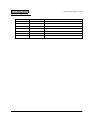
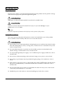
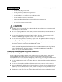


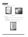


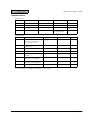
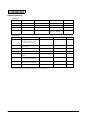


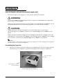
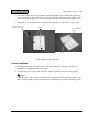
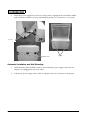
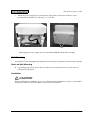
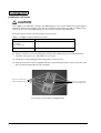
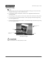
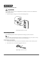
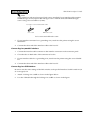
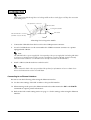

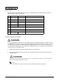


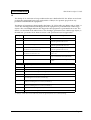


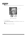
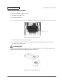
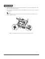

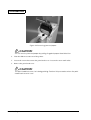
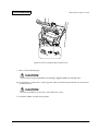
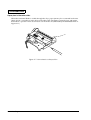
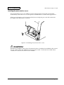

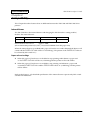

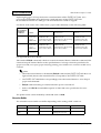
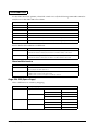
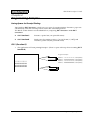
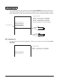
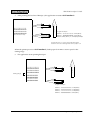

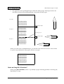


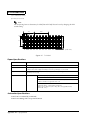
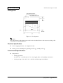
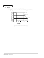
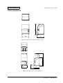


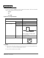


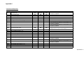

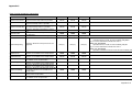
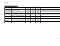


![SS400G MLSS Converter [Style:S2.2]](http://vs1.manualzilla.com/store/data/005726371_1-b873ef07ceb169a0226d293b313a67fd-150x150.png)