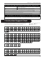
1
PNC-960
PNC-910
USER'S MANUAL
* This User's Manual is intended for PNC-960 and PNC-910.
For the USA
FEDERAL COMMUNICATIONS COMMISSION
RADIO FREQUENCY INTERFERENCE
STATEMENT
This equipment has been tested and found to comply with the
limits for a Class B digital device, pursuant to Part 15 of the
FCC Rules.
These limits are designed to provide reasonable protection
against harmful interference in a residential installation.
This equipment generates, uses, and can radiate radio
frequency energy and, if not installed and used in accordance
with the instructions, may cause harmful interference to radio
communications.
However, there is no guarantee that interference will not
occur in a particular installation.
If this equipment does cause harmful interference to radio or
television reception, which can be determined by turning the
equipment off and on, the user is encouraged to try to correct
the interference by one or more of the following measures:
- Reorient or relocate the receiving antenna.
- Increase the separation between the equipment and
receiver.
- Connect the equipment into an outlet on a circuit different
from that to which the receiver is connected.
- Consult the dealer or an experienced radio/TV technician
for help.
NOTICE
Grounding Instructions
Do not modify the plug provided - if it will not fit the outlet,
have the proper outlet installed by a qualified electrician.
Check with qualified electrician or service personnel if the
grounding instructions are not completely understood, or if in
doubt as to whether the tool is properly grounded.
Use only 3-wire extension cords that have 3-prong
grounding plugs and 3-pole receptacles that accept the tool’s
plug.
Repair or replace damaged or worn out cord immediately.
Operating Instructions
KEEP WORK AREA CLEAN. Cluttered areas and benches
invites accidents.
DON’T USE IN DANGEROUS ENVIRONMENT. Don’t
use power tools in damp or wet locations, or expose them to
rain. Keep work area well lighted.
DISCONNECT TOOLS before servicing; when changing
accessories, such as blades, bits, cutters, and like.
REDUCE THE RISK OF UNINTENTIONAL STARTING.
Make sure the switch is in off position before plugging in.
Unauthorized changes or modification to this system can void
the users authority to operate this equipment.
The I/O cables between this equipment and the computing
device must be shielded.
USE RECOMMENDED ACCESSORIES. Consult the
owner’s manual for recommended accessories. The use of
improper accessories may cause risk of injury to persons.
NEVER LEAVE TOOL RUNNING UNATTENDED.
TURN POWER OFF. Don’t leave tool until it comes to a
complete stop.
For Canada
CLASS B
NOTICE
This Class B digital apparatus meets all requirements of the
Canadian Interference-Causing Equipment Regulations.
CLASSE B
AVIS
Cet appareil numérique de la classe B respecte toutes les
exigences du Règlement sur le matériel brouilleur du
Canada.
YEARS OF
ROLAND DG CORPORATION
MANUFACTURE
1227 Ohkubo-cho, Hamamatsu-shi, Shizuoka-ken, JAPAN 432
MODEL NAME
: See the MODEL given on the rating label.
1997
RELEVANT DIRECTIVE : EC MACHINERY DIRECTIVE (89/392/EEC)
EC LOW VOLTAGE DIRECTIVE (73/23/EEC)
EC ELECTROMAGNETIC COMPATIBILITY DIRECTIVE (89/336/EEC)
Table of Contents
Thank you very much for purchasing the CAMM-1 PNC-960/910.
- To ensure correct and safe usage with a full understanding of this product's performance, please be sure to read through this
manual completely and store it in a safe location.
- Unauthorized copying or transferal, in whole or in part, of this manual is prohibited.
- The contents of this operation manual and the specifications of this product are subject to change without notice.
- The operation manual and the product have been prepared and tested as much as possible. If you find any misprint or error,
please inform us.
Table of Contents
Typographic Conventions ............................................................................................................................................. ii
To Ensure Safe Use .................................................................................................................. iii
About the Labels Affixed to the Unit ................................................................ iv
1
2
3
4
To Ensure Correct Use ..................................................................................................................................... iv
Checking Supplied Items ...................................................................................................................................... 1
Part Names and Functions
2-1 Front View .......................................................................................................................................................... 1
2-2 Rear View ............................................................................................................................................................................ 2
2-3 Operation Panel ................................................................................................................................................................... 2
Basic Operation
3-1
Setting Up and Connection .................................................................................................................................................. 3
3-2
3-3
DIP Switch Settings ............................................................................................................................................................. 4
Installing/Removing a Blade ............................................................................................................................................... 5
3-4
3-5
Loading/Removing the Material .......................................................................................................................................... 6
Setting the Origin Point — , , , , ORIGIN SET Keys .......................................................................................... 10
3-6
3-7
Cutting Test to Check Blade Force — , , , , and TEST Keys .............................................................................. 11
Downloading Cutting Data .................................................................................................................................................. 12
3-8
3-9
Applying the Completed Cutout .......................................................................................................................................... 13
When Cutting is Completed ................................................................................................................................................ 13
Settings For Each Function
4-1
Using a material effectively and cutting along the vertical dimension (Rotate function) — ROTATE Key and ROTATE LED ....... 15
4-2
Plotting on Paper Media — PEN MODE Key and PEN MODE LED ....................................................................... 16
5
About the Blade ...................................................................................................................................................... 17
6
What to do if ............................................................................................................................................................ 18
7
Instruction Support Chart ...................................................................................................................................... 19
8
Character Sets ........................................................................................................................................................ 20
9
Specifications .......................................................................................................................................................... 21
i
Typographic Conventions
Typographic Conventions
This manual uses certain typographic symbols, outlined below.
This indicates a point requiring particular care to ensure safe use of the product.
: Failure to heed this message will result in serious injury or death.
: Failure to heed this message may result in serious injury or death.
: Failure to heed this message may result in minor injury.
: Indicates important information to prevent machine breakdown or
malfunction and ensure correct use.
: Indicates a handy tip or advice regarding use.
Windows is a registered trademark or trademark of Microsoft Corporation in the United States and/or other countries.
Copyright © 1996 ROLAND DG CORPORATION
ii
To Ensure Safe Use
To Ensure Safe Use
Never disassemble or modify
this product.
Handle the power cord with care.
Do not step on or damage the power
cord, or allow heavy objects to be
placed atop it. Failure to heed this may
result in
electrocution
or fire.
Do not allow liquids, metal
objects or flammables inside the
machine.
Do not install in an unstable or
high location.
Fire or
breakdown
may result.
Do not
installation the
machine on the
edge of a table,
or it may fall.
Ensure the safety of the area
around the platen before
switching on the power.
Do not inadvertently allow the
hands, hair, or necktie near the
carriage while in operation.
When pulling the power cord
from an electrical socket, be
sure to grip the plug.
Handle the blade with care.
Do not place hands near the
platen while in operation.
The carriage moves simultaneously
when the power is switched on.
iii
About the Labels Affixed to the Unit/To Ensure Correct Use
About the Labels Affixed to the Unit
These labels are affixed to the body of this product. The following figure describes the location and content of these messages.
Do not allow the hands near the
platen while in operation.
Rating label
To Ensure Correct Use
This product is a precision instrument
and must be handled with care.
When the unit is not in use for an
extended period, detach the electrical
plug from the AC outlet.
iv
Do not install in an area subject to dust,
high humidity or poor ventilation.
Do not connect to an AC outlet that
supplies other than the specified voltage.
1 Checking Supplied Items/2 Part Names and Functions
1 Checking Supplied Items
Check the following to make sure that you received all the items that were shipped along with the unit.
Power Cord:1
Blade (ZEC-U1005):1
Blade Holder (XD-CH3):1
Roller Base:1
Cutter Tool:1
Tweezers:1
Test-use High-quality Paper/Material for
Test Cuts/Test-use Application Tape:
1 piece each
Test-use Water-based Fiber-tipped Pen:1
*PNC-960 only
*PNC-960 only
*PNC-960 only
User's Manual:1
CAMM-1 DRIVER for windows 95:1
CAMM-1 DRIVER for windows 3.1:1
2 Part Names and Functions
* In this manual, the sections that explain both the PNC-960 and
the PNC-910 shown only illustrations of the PNC-960.
2-1 Front View
Movable Pinch Roller (Left)
Press material against the grit roller.
This is aligned with the left edge of the loaded
material and set in place.
Tool Carriage
The tool (blade or plotting pen) is
installed here. The tool carriage performs
the cutting by moving the tool left/right
or up/down.
Pen Force Control Slider
Sets the blade force to be used with the tool.
DIP Switches
Used to make various settings.
Guide Line Mark
Material is loaded in
alignment with the guideline marks.
Grit Roller
This moves the material
to the front and rear.
Serial (RS-232C) Input Connector
Cutter Protector
The tool carriage moves
above the blade
protector, and cutting is
carried out here.
Operation Panel
Platen
The material is moved over the
platen.
In a serial configuration, this connector is
where you need to connect the serial cable that
is used to communicate with your computer.
Parallel (Centronics) Input Connector
Movable Pinch Roller (Right)
Press material against the grit roller.
This is aligned with the right edge of the
loaded material and set in place.
In a parallel configuration, this connector is where
you need to connect the parallel cable in order to
communicate with your computer.
1
2 Part Names and Functions
2-2 Rear View
Sheet Loading Lever
This moves the pinch rollers up and
down to load and release the material.
Power Connector (AC IN)
This connector accepts standard AC
power cord.
Power Switch
ON when switched to [I].
OFF when switched to [O].
2-3 Operation Panel
* The TEST key and the position keys function only
when the SETUP LED is lighted, and the ROTATE key
functions only when the SETUP LED is not lit.
SETUP Key
Press this to detect the width of the loaded
material and enable the unit for cutting.
Pressing this while operation is paused deletes
the data sent from the computer.
SETUP LED
This lights up when the SETUP key is pressed.
Cutting can be performed when this is lit.
PAUSE LED
PAUSE Key
This lights up when the PAUSE key is pressed to
pause the PNC-960/910.
When pressed once, this temporarily halts
cutting in progress. Pressing this key again
releases the paused state.
PEN MODE LED
This lights up when the PEN MODE key is
pressed.
PEN MODE Key
Press this to perform plotting with a pen on
paper. (Be sure to load a pen in the tool
carriage.)
ROTATE LED
This lights up when the ROTATE key has been
pressed.
TEST LED
ROTATE Key
Pressing this key sets the origin point at the
bottom right of the material and rotates the
direction of cutting by 90°.
This lights up when the TEST key is pressed.
TEST Key
(Position Keys)
These are used to move the material or the tool
carriage.
This performs a cutting test to check whether
blade force is correct.
ORIGIN SET Key
POWER/ERROR LED
This sets the origin point for cutting to the
current tool position.
This lights up when the power is switched on,
and flashes when an error is generated.
The PEN MODE LED and POWER/ERROR LED blink simultaneously.
This flashes if the location of the pinch rollers is not correct, if DIP switch SW-9 on the PNC-960 is set to ON (piece material) and material
with a vertical length of 100 mm (3-15/16") or less has been loaded, or if SW-9 is set to ON and there is no material over the front and rear paper sensors.
For more details, see "3-4 Loading/Removing the Material".
2
3 Basic Operation
3 Basic Operation
3-1 Setting Up and Connection
When arranging setup space for the PNC-960, make sure you have a space that is at least 950 mm (37-7/16") wide, 500 mm (19-11/
16") in depth, and 230 mm (9-1/16") in height. For the PNC-910, a space that is at least 650 mm (25-5/8") wide, 500 mm (19-11/16")
in depth, and 230 mm (9-1/16") in height.
Since the material moves during cutting, make sure the unit is placed on a stable, sturdy surface. Also make sure there is nothing that
can block the material at both front and rear.
- Do not try to pick up or move the PNC-960/910 by grasping the top area of the unit. Be sure to use both hands to grip the PNC960/910 securely on the left and right sides.
- Connect the cable to either the parallel or the serial port. Be sure that the power to both the computer and the main unit is
switched off when connecting the cable.
- Avoid places subject to strong electrical noise.
- Avoid excessively dusty or damp places.
- Never leave the unit in a place that is subject to direct sunlight, or where the temperature could go to extremes.
- Since it is normal for this device to emit heat when in operation, never place it where it is poorly ventilated and such heat cannot
dissipate.
Power outlet
Power connector
Power cord
Serial input connector
Parallel input connector
Serial interface cable
(Connect to the serial input port.)
Serial connector
or
Parallel connector
* Cables are available separately. One which you are
sure matches the model of computer being used
should be selected.
Parallel interface cable
(Connect to the parallel input port.)
* When the PNC-960/910 is connected to the computer via the serial
port, the communication parameters (Baud, Data, Parity, Stop,
etc.) for the PNC-960/910 need to match the port settings on the
computer. Use the DIP switches on the right-hand side of the PNC960/910 to make these settings. Refer to "3-2 DIP Switch
Settings" to make the correct settings.
3
3 Basic Operation
3-2 DIP Switch Settings
DIP switches settings must be made only when the power is turned off.
DIP switch
Function
OFF
ON
SW-1
Baud rate
9600
4800
SW-2
Parity check
Disable
Enable
SW-3
Parity check
ODD
EVEN
SW-4
Data bits
8-bits
7-bits
SW-5
Stop bits
1-bit
2-bits
SW-6
Handshake
Hardwire
XON/OFF
SW-7
Blade offset
0.25
0.175
Long output mode
Light
Heavy
Material size
Roll
Piece
Smoothing
ON
OFF
SW-8
SW-9
SW-10
*
* On the PNC-910, SW-9 is not used.
This switch should always be set to "OFF."
- All DIP switches are set to OFF when shipped from the factory.
- When SW-2 is set to OFF, SW-3 may be set to either ON or OFF.
- When SW-8 has been set to ON (heavy), cutting speed is limited to the range of 10 to 100 mm/sec. At this time, operation never
exceeds 100 mm/sec., even is an instruction for a speed greater than 100 mm/sec. is received from the computer.
SW-1—6
SW-7
SW-8
SW-9
SW-10
4
: Sets the communication parameters for a serial connection. When the PNC-960/910 is connected to the computer
through the serial port, be sure that the communication parameters for SW-1 to SW-6 are set correctly, matching the
computer port settings.
: Sets the amount of offset for the cutter blade. Set to OFF when using a tool with a blade offset of 0.25 mm, or to
ON when using a tool with a blade offset of 0.175 mm.
SW-7, which controls the blade offset, should normally be set to OFF (0.25 mm).
: Sets the weight of the material. If the material is not cut even when the blade force has been increased, set this
switch to ON (heavy). When set to ON, the upper limit for cutting speed is set to 100 mm/sec., and the force used
to move the material and the blade increases. This switch should normally be set to OFF (light).
: Sets the size of the material. Set this to ON when using a piece material (piece), and set it to OFF (roll) when using a
rolled material.
: Smoothing is a function for cutting smooth circles and arcs. Smoothing is enabled when this switch is set to OFF
(enabled).
3 Basic Operation
3-3 Installing/Removing a Blade
Always make sure the power switch is OFF before installing (or removing) the cutter.
- Do not touch the tip of the blade with your fingers, as the cutting performance of the blade will be impaired.
- Be sure to support the tool mounting screw from below when installing the blade holder.
Cutting quality may become poor if installed without supporting the screw in this way.
Installing the Blade
Insert a blade into the blade
holder until it snaps into place
with an audible click.
Push-pin
Blade holder
Blade
1
(1) Loosen the tool securing screw
on the tool carriage. Support the
tool-securing screw from below
and install the blade holder.
Insert the blade holder until the
collar is flush with the carriage.
(2) Tighten the tool securing screw
until the blade holder is secured Tool securing screw
in place.
2
Adjusting the Cutter Blade
The amount of cutter blade extension can be adjusted by rotating the cap. Refer to the figure below to adjust the blade before
installing it on the tool carriage.
[When the Tip of the Blade Is Set to 0 mm]
Each indicator tick corresponds to 0.1 mm, and adjustment
for 0.5 mm can be made by rotating the cap one full turn
Perform a cutting test and gradually extend the blade.
Take care to ensure that the amount of blade extension does not exceed the thickness of the material
portion plus the thickness of the base paper.
Amount of cutter
Blade extension
Min. :0 mm
Max. :2.5 mm
For a material included with the unit,
or a general type of equivalent material
For materials where the base paper is thin with respect
to the material (material thickness), and cutting is carried out
without fine adjustment of blade force
For cases where material thickness is not accurately known
Thickness of
Thickness of
Amount of
cutter blade = the material + the base paper
portion
extension
2
If the blade leaves a faint mark on the base paper, the
amount of blade extension is optimal.
Removing the Blade
Do not leave the tool mounting screws tightened. Tightening the screw makes it more difficult to install the blade holder.
(1) Loosen the tool securing
screw on the tool carriage.
(2) Remove the blade holder from
the tool carriage.
Tool carriage
Press the push-pin and remove the
blade from the blade holder.
Push-pin
Blade holder
Blade
Tool securing screw
1
2
5
3 Basic Operation
3-4 Loading/Removing the Material
Turning on the Power
Switch on the power switch on the left side of the PNC-960/910.
When the power switch is pressed to turn on the unit, the tool carriage moves. Use caution to ensure that
your hands or other objects do not become caught in the moving parts.
Loading the Material
The PNC-960/910 can use either flat material such as regular-sized materials and scraps, or roll material. When using roll material
on the PNC-910, it is necessary to install the roller base sold separately.
Acceptable media widths
Width (horizontal dimension)
Length (vertical direction)
PNC-960
50—711 mm (1-15/16"—28")
100 mm (3-15/16") or more when DIP switch SW-9 is set to
"ON"
No other restrictions
(* Accuracy assured within a range of up to 1,600 mm (63"))
PNC-910
50—406 mm (1-15/16"—16")
No restrictions
(* Accuracy assured within a range of up to 1,600 mm (63"))
Depending on the type of material, it may be necessary to make DIP switch settings on the PNC-960. To do this, first switch of the
power to the unit, then set DIP switch SW-9 to ON if loading piece material, or to OFF if loading roll material. After making the
setting, turn the PNC-960 back ON. On the PNC-910, it is not necessary to make any DIP switch settings.
The grit rollers on the PNC-960 are divided into four areas that can secure the material with the pinch rollers. Also, The grit rollers
on the PNC-910 are divided into two separate areas. The range of movement is determined by the movable pinch rollers on the left
and right (see "Reference"). Experiment with the range of the left and right movable pinch rollers to determine usable area.
When loading a material, first place it atop the grit rollers and make sure that it is positioned where it can be secured by the pinch
rollers.
:Grit Roller
Reference -- Material Loading Position
:Movable Pinch Roller (Left)
6"
(approx. 152 mm)
:Movable Pinch Roller (Right)
Material
12"
(approx. 305 mm)
18"
(approx. 457 mm)
24"
(approx. 610 mm)
PNC-960
Position of the pinch roller
(right) for material with
a width of 6"
Position of the pinch roller
(right) for material with
a width of 12"
Position of the pinch roller
(right) for material with
a width of 18"
Position of the pinch roller
(right) for material with
a width of 24"
*Do not set the pinch roller here.
28" (approx. 711 mm)
PNC-910
Position of the pinch roller
(right) for material with
a width of 6"
Position of the pinch roller
(right) for material with
a width of 12"
*Do not set the pinch roller here.
16" (approx. 406 mm)
The left-hand movable pinch roller can be moved within this range.
When loading material with a width other than one indicated above, move the left-hand movable pinch roller.
6
3 Basic Operation
- If you are using roll material, start with step 1.
- If you are using piece material, start with step 2.
- When using sprocket-feed paper, start with step 1 on the following page.
Raise the sheet loading lever.
[If You Are Using the Roller Base]
[If You Are Not Using the Roller Base]
Install the roller base on the back of the
unit and place the roll material on the base.
Load the material as shown below.
Pull out the length of
material that is to be cut
from the roll.
Cut off the length of
material that is to be cut
from the roll.
Do not load the
material as shown in
the figure, because
correct material feed
will be impossible.
1
Pass the end of the material between the pinch rollers and the grit rollers so that it extends
from the front of the unit..
Align both edges of the material with the grit
rollers. Use the guide lines to load the material so
that it is perfectly straight with respect to the unit.
- There are two guide-line marks on the front
surface of the unit.
- Align the left-hand edge of the material with the
same guide-line marks.
Move the left and right movable pinch rollers to
the left and right edges of the material.
- If a pinch roller does not move easily, it may
help to grasp the corresponding pinch roll frame
at the back of the unit and move it together with
the pinch roller.
Movable pinch roller (left)
[Front View]
[Rear View]
Pinch roll
frame
Material
Guide-line mark
2
The tool carriage moves when the SETUP key is pressed. Take care to ensure that your hands or other
objects do not get caught in the moving parts.
Lower the sheet loading lever.
- The pinch rollers are lowered and the material is secured in
place.
Sheet loading lever
3
Press the SETUP key.
- The width of the material is detected and the unit is made
ready for cutting.
- The tool carriage moves to the cutting origin point.
4
Press the
key to feed out the length of material to be cut to
the front of the PNC-960/910.
Press the
key to return the material back through to the rear
of the unit.
- If the material slips or comes loose, follow the steps to load
the material again.
5
7
3 Basic Operation
If you are using any of the following kinds of materials, neither of the methods described earlier will result in correct cutting.
- A material with edge holes for sprocket feed that has no material layer (only base paper) along the hole area at the edges
* If you are using the PNC-960 and DIP switch SW-9 is set to ON (piece material), then turn off the power, set DIP switch
SW-9 to OFF (roll material), and switch the power back on. On the PNC-960, it is not necessary to make any DIP switch
settings.
Pass the end of the material between the pinch rollers and the
grit rollers so that it extends from the front of the unit.
If you are using roll material, then install the roller base on the
back of the unit, place the roll material on the base, and pull
out the length of material that is to be cut from the roll.
Align both edges of the material with the grit rollers. Use the
guide lines to load the material so that it is perfectly straight
with respect to the unit.
- There are two guide-line marks on the front surface of the
unit.
- Align the left-hand edge of the sheet with the same guide-line
marks.
1
2
Move the left and right movable pinch
rollers to the left and right edges of the
material.
- If a pinch roller does not move easily, it
may help to grasp the corresponding pinch
roll frame at the back of the unit and move
it together with the pinch roller.
Movable pinch roller (left)
[Rear View]
Pinch roll
frame
Material
[Front View]
Guide-line mark
3
The tool carriage moves when the SETUP key is pressed. Take care to ensure that your hands or other
objects do not get caught in the moving parts.
Lower the sheet loading lever.
- The pinch rollers are lowered and the material is secured in
place.
- When using scrap material or unfomed material, do not put
the pinch rollers at the far ends of the materials.
- When using sprocket-feed paper, do not put the pinch rollers
on the hole area at the edges.
Press the SETUP key.
- The width of the material is detected and the unit is made
ready for cutting.
- The tool carriage moves to the cutting origin point.
4
5
Removing the Material
Press the SETUP key. Hold down for about 1 sec.
The SETUP LED goes out and the tool carriage moves to the
right edge of the cutting area.
(1) Raise the sheet loading lever.
(2) Remove the material.
The SETUP LED
goes out
1
8
Material
Sheet loading lever
2
3 Basic Operation
To Perform Long Cutting
When performing cutting over a length of 1.5 m (60") or more, first feed out the required length of material. Then follow the
steps below to load the material.
4
1
Pull out the material from the roll and
pass it through the unit.
Pull out the amount of
roll material to be used.
Use material that is wider by 50 mm (2") or more than
the width of the cutting to be performed.
2
25 mm
(1")
or more
25 mm
(1")
or more
3
Guide line
marks
Guide line
marks
5
Press the SETUP
key.
6
Feed out the length
of material to be cut.
7
Return the fed-out
material.
Make sure that the material
remains held by the pinch
rollers.
If the material does come
loose from the pinch rollers,
set it in place again.
9
3 Basic Operation
About the Cutting Area
Max.
584 mm (23")
Max.
280 mm (11")
Cutting Area
Material
Movable Pinch
Roller (Left)
About 1 mm
(about 0.04")
Max.
24,998 mm (984-1/8")
(Accuracy assured
within a range of up
to 1,600 mm (63"))
Max.
24,998 mm (984-1/8")
(Accuracy assured within a
range of up to 1,600 mm (63"))
About 15 mm
(about 9/16")
Initial cutting
coordinate origin
point (0,0)
Movable Pinch Roller (Right)
Movable Pinch Roller (Right)
[PNC-960]
[PNC-910]
* The arrows in the figure indicating
the X and Y directions indicate
respectively the positive directions
of the X axis and Y axis when the
Rotate function is off.
3-5 Setting the Origin Point —
,
,
,
, ORIGIN SET Keys
The PNC-960/910 allows the origin point (0,0) to be set at any position in the cutting area.
Loading material and pressing the SETUP key causes the first origin point to be determined. The first origin point determined by
pressing the SETUP key varies according to the model and the DIP switch settings.
DIP switch
PNC-960
PNC-910
Position where the origin point is set
SW-9 OFF (roll material)
Set near the left-hand movable pinch roller
SW-9 ON (piece material)
Material size is detected and the origin is set at the lower-left
area of the material
On the PNC-910, it is not necesary to make any DIP switch
settings
Set near the left-hand movable pinch roller
Pressing the ROTATE key (making the ROTATE LED light up) sets the origin to a point the right-hand movable pinch roller.
If there is no need to move the origin initially set, then it is not necessary to make the origin point setting immediately after
loading a material.
You can also set the origin to an uncut area of a material in order to use the material with maximum effectiveness.
* If a material has not yet been loaded, then before setting the origin point, refer to "3-4 Loading/Removing the
Material" to load the material correctly. Loading a material after the origin has been set (by pressing the SETUP
key to extinguish the SETUP LED) cancels the origin that has been set.
Press the , , , and
keys to move the tool carriage.
Move the tool carriage to the point where the origin is to be set.
1
10
Press the ORIGIN SET key.
The SETUP LED flashes once and the origin point is set.
2
3 Basic Operation
3-6 Cutting Test to Check Blade Force — , , , , and TEST Keys
Before carrying out actual cutting, you may wish to perform a "cutting test" to check whether the unit produces the cutout
satisfactorily.
This "cutting test" allows you to determine whether the settings you have for the blade force are appropriate. See below for a
detailed explanation of blade force.
* If a material has not yet been loaded, then refer to "3-4 Loading/Removing the Material" to load the material
correctly.
To start with, move the pen force control to the left-most indicator mark (minimum blade force).
Increase blade force gradually, until cut quality is satisfactory.
Press the , , , and
keys to move the tool carriage.
Move to the position where the cutting test is to be performed.
Press the TEST key.
Cutting test starts.
The TEST LED
lights up
* Note that an area of approximately 2 square centimeters (a little less than a square inch) is required to make
a test cutout (given that the tip of cutter after it has
moved is at the origin at lower-left).
1
2
(1) First peel off the round section (shaded as shown
).
- When it can be peeled off by itself, without disturbing the square, the blade force is set
appropriately.
(2) Next, peel off the square, and look at the backing behind it.
- The optimum blade pressure is correct if you can clearly make out the lines left by the
blade.
* Adjust the pen force control slider until results as shown above are obtained.
(Gradually increase the cutter force until you reach the optimum level.)
Peel off first
Then peel this off
Origin
3
How to Adjust Blade Force
When making the blade force setting, it is important to take into consideration the hardness of the blade as well as the
thickness and type of the material to be cut, and adjust blade force accordingly. If the blade force is weak, the material
may not be cut satisfactorily. If the blade force is too strong, blade life will be shortened and cutting may be impaired.
The pen force control slider is located on the right
side of the unit. Move the blade force control slider
sideways to alter the blade force.
The pen force control slider can be positioned at
marks indicating the 11 levels available.
Blade Force
DOWN
UP
MIN 2 4 6 8 MAX
Additionally, be aware that problems such as the following may occur.
- The material may be torn
- The blade may pierce the material and backing
- Cutter blade extends through the base paper, and normal
advancing of the material becomes impossible
- The unit may suffer damage
PEN FORCE
Max. Blade Forc
11
3 Basic Operation
3-7 Downloading Cutting Data
The unit will begin cutting when it receives cutting data sent from the computer.
Software Settings
- When cutting with commercially available application software, select PNC-960/910 as the setting for the output device. (If the
PNC-960/910 cannot be selected, choose any model in the PNC-1100, PNC-950, or PNC-900).
- Select either the parallel (Centronics) or serial (RS-232C) interface. Choose the one that the host computer and the PNC-960/910
are connected by.
- When loading a flat material the PNC-910 that has been cut, be sure to use a flat material that is about 50 mm (1-15/16") longer
than the vertical size of the cutting data. If data larger than the vertical length of the material is sent, the PNC-910 will attempt to
cut the data even if it does not all fit in the material. This means that the material is dislodged from the grit roller, and cutting
continues with no material. This can cause not only breakage to the blade but also damage to the unit, and adequate care is
required to prevent this.
- If the material becomes dislodged, immediately press the PAUSE key or turn off the power switch.
Pausing Cutting Operations — PAUSE Key, PAUSE LED, and SETUP Key
If you wish to pause operation while cutting is in progress, follow the steps described below.
Press the PAUSE key.
Cutting is paused.
The PAUSE LED
lights up
1
[To Resume Cutting]
(1) Press the PAUSE key.
(2) Cutting is resumes.
[To Terminate Cutting]
The PAUSE LED
goes out
(1) Halt transmission of cutting instructions from the
computer.
(2) Hold down the SETUP key.
The SETUP LED
goes out
* Cutting instructions already sent from the computer
to the PNC-960/910 are deleted, the tool carriage
moves to the right, and cutting stops.
Continuing Cutting
[Cutting After Changing the Material]
[Continuing Cutting on the Same Material]
Follow the procedure described from "3-4
Loading/Removing the Material" to "3-7
Downloading Cutting Data" .
Refer to "3-5 Setting the Origin Point" and set the origin at a place which has
not yet been cut (i.e., at the place to be cut next).
Then send cutting data from the computer to the PNC-960/910.
* If the same type of material is used, then
a cutting test is not necessary.
12
2
3 Basic Operation
3-8 Applying the Completed Cutout
Once cutting has been completed, follow the procedure below for application instructions.
- Make sure beforehand that the surface where the work is to be stuck is clean and free of all dust or oily deposits.
- When applying the work to a transparent surface, such as a window, you can use a water-based pen (which can be
wiped off afterwards) to mark guidelines on the reverse side of the glass, to aid in getting the work aligned properly.
- If you discover after it is stuck in place that air bubbles were trapped under the work, use a needle to puncture them.
Then you can smooth out the material out so that it sticks securely.
[For Piece Materials]
Refer to "3-4 Loading/Removing the Material" to remove the
material from the PNC960/910.
[For Roll Materials]
Use the cutter tool or scissors to detach the work area from the
rolled material.
* The PNC-910 uses scissors or something
similar to sever from the roll material.
Strip/Weed uses all unneeded portions from the completed
work.
* You should have weed
boarders or rectangles
drawn around work to
facilitate weeding.
Stick application tape over the completed work.
Press down firmly on the application tape to remove air
bubbles. If you do not press firmly enough the cut area will not
stick to the surface.
Transfer the material to the
application tape, position it,
and carefully affix it, making
sure that it is aligned correctly.
Rub over the application tape
to make sure the work is firmly
stuck in place. Then peel off
the application tape.
1
3
2
4
3-9 When Cutting is Completed
(1) When cutting is finished, raise the sheet loading lever and
remove the material. (Refer to "3-4 Loading/Removing the
Material".)
(2) If a blade was used, wipe the blade with a soft cloth to
remove any pieces of the material that may be adhering to
it.
1
Turn off the power.
* If you do not intend to use the unit for an extended
period of time, you should pull the plug for the power
cord out of the outlet.
2
* Use a soft cloth to wipe down the PNC-960/910.
13
3 Basic Operation
Performing a Self-test
The PNC-960/910 is equipped with a "self-test" function to conveniently allow you to check whether or not it is capable of operating
normally. If the PNC-960/910 is not performing correctly, follow the steps below to perform a self-test.
* A computer is not required in order to carry out the self-test.
Refer to "3-3 Installing/Removing a Blade" and install a blade
holder (or pen) in the PNC-960/910's tool carriage.
Set the pen force to the smallest possible value (the pen force
slider should be at the furthest point to the left). If after the
cutting test you feel that the material was not cutout clean
enough, you can try gradually increasing the pen force until
you have the optimum level.
1
Hold down the
on.
key on the panel while you turn the power
2
Load the material (or some paper), following the procedure
described in "3-4 Loading/Removing the Material" .
ON
+
* If a pen and material have been loaded, press the
PEN MODE key to light up the PEN MODE LED.
POWER ON
OFF
3
Press the SETUP key.
Demo cutting starts.
Operations is normal if
the figure shown at right is
cut.
14
The SETUP LED
lights up
5
4
4 Settings For Each Function
4 Settings For Each Function
4-1 Using a material effectively and cutting along the
vertical dimension (Rotate function) -- ROTATE Key
and ROTATE LED
This function sets the origin point at the bottom right and rotates the text or graphics 90° (see pictures below). This function is
used when the intended design will not fit in the width (horizontal dimension) of the material, such as long strings of text. If there
is still unused material on the right side, rotation allows you to use this remaining material effectively.
When the character string “Roland” is rotated by 90°, the X axis, Y axis, and origin change as follows:
0° Rotation - Rotate OFF
90° Rotation - Rotate ON
Origin
Origin
* The pairs of arrows indicate the positive directions along the X and Y axis.
Check that the SETUP LED has
gone out, and press the ROTATE
key.
The ROTATE LED
lights up
* If the SETUP LED is lit up, the
Rotate function is disabled and will
not work.
Press the SETUP key to extinguish
the SETUP LED, then press the
ROTATE key again.
Press the SETUP key.
The SETUP LED lights up and the
tool carriage moves to the left and
right, then returns.
1
The SETUP LED
lights up
2
Send cutting data from the computer.
3
Canceling the Rotate Function
After holding down the SETUP key for about one second to make the SETUP LED go out, press the ROTATE key. The ROTATE LED
is extinguished, and the origin returns to the point at bottom left.
The ROTATE function is also canceled when the power to the PNC-960/910 is turned off.
15
4 Settings For Each Function
4-2 Plotting on Paper Media -- PEN MODE Key and PEN
MODE LED
The PNC-960/910 is also capable of plotting on paper media using plotter pens made by this company. Before cutting, plotting
using pen and paper can ensure that your design is correct without wasting materials.
* Since the design of the PNC-960/910 differs inherently from that of dedicated plotters, it does not accommodate
functions such as high-speed plotting, automatic pen changes, pen dry protection, or the like.
Acceptable pens and paper media
Acceptable paper
PNC-960
Acceptable paper widths
Acceptable pens
50 mm (1-15/16") — 711 mm (28")
Water-based fiber-tipped pens
Thick water-based fiber-tipped pens
32 color plotter pens
High-quality paper
PNC-910
50 mm (1-15/16") — 406 mm (16")
- If you are using the PNC-960, then start with step 1.
- If you are using the PNC-910, then start with step 2.
Set DIP switch SW-9 to ON (piece). (Refer to "3-2 DIP Switch
Settings".)
Refer to "3-3 Installing/Removing a Blade" and install a pen in
the same way as you would install a blade.
1
2
Refer to "3-4 Loading/Removing the Material" and load a
material in the same way as you would load cutting material.
You can load a material with a width (horizontal dimension) of
50 (1-15/16") to 711 (28") mm on the PNC-960, or a material
with a width (horizontal dimension) of 50 (1-15/16") to 406
(16") mm on the PNC-910.
Press the PEN MODE key.
3
The PEN MODE
LED lights up
4
Plotting begins when plotting instructions are sent from the
computer.
5
Stopping Plotting on Paper Media
Press the PEN MODE key. The PEN MODE LED is extinguished and the unit returns to the cutting mode.
Remove the pen from the tool carriage and cap it securely.
Pen Replacement
Pens will eventually wear out. Should the tip become rough and produce scratchy lines, try gradually increasing the blade force
(refer to "3-6 Cutting Test to Check Blade Force" ). If smudging occurs even when pen force is increased, or if the pen tip becomes
frayed, replace with a new pen.
16
5 About the Blade
5 About the Blade
This section indicates the proper cutting conditions for various types of materials, as well as blade lifespans. Cutting conditions and
blade life may vary according to the quality of the material and conditions of use.
Making the settings for the conditions described below does not automatically guarantee attractive cutting results in all situations.
Before performing actual cutting, be sure to carry out a cutting test and make any necessary adjustments (refer to "3-6 Cutting Test to
Check Blade Force" ). If cutting is incomplete even after using the pen-force scale in the following table to increase pen force by at
least three or four scale marks, it means that the useful life of the blade has ended. Replace with a new blade.
Blade
Material
Pen-force scale
Speed
Amount of cutter
blade extension
Life of a
blade
ZEC-U1005
General Signage Vinyl
1—7
40 cm/sec.
0.25 mm (0.01")
8000 m
ZEC-U5025
General Signage Vinyl
Reflective Vinyl
Fluorescent Vinyl
MIN — 4
5 — MAX
4 — MAX
40 cm/sec.
0.25 mm (0.01")
4000 m
ZEC-U1715
Rubber material for
sandblasting stencil
4 — MAX
20 cm/sec.
0.25 mm (0.01")
Varies
according to
material type
* The values for lifespan are intended to serve as a general guide when cutting materials of identical type.
Rubber materials for sandblasting stencils which can be cut: Materials with a material thickness of 1 mm (0.04") or less
Materials with only carrier paper on both flanks of the material
(Position the left and right pinch rollers above the strips of carrier
paper.)
Materials with carrier paper which is hard enough to withstand
material feed
Material
1 mm (0.04")
or less
15 mm (9/16")
or more
Carrier paper
17
6 What to do if...
6 What to do if...
If the PNC-960/910 doesn't run...
Is the PNC-960/910 power on?
Turn on the power (refer to "3-4 Loading/Removing the Material Turning on the Power").
Is the unit in SETUP status (the SETUP LED is
lit)?
If the SETUP LED is not illuminated, make sure the sheet is loaded correctly and press the
SETUP key to illuminate the SETUP LED.
Is the PAUSE LED illuminated?
If the PAUSE key has been pressed and the PAUSE LED is lit up, the unit has been paused
(refer to "3-7 Downloading Cutting Data Pausing Cutting Operations").
If you want to resume cutting, press the PAUSE key again. The PAUSE LED is extinguished,
and cutting resumes. If you want to terminate cutting, first stop the transmission of cutting
instructions from the computer to the PNC-960/910. Then press the SETUP key. This deletes
the cutting instructions that have already been sent from the computer to the PNC-960/910, and
cutting is stopped.
If connected via the serial port, do the
communication parameters for the PNC-960/
910 match those of the computer?
Set the DIP switches correctly (refer to "3-2 DIP Switch Settings").
Is the computer set up correctly?
Check the following items:
- DIP switches - Memory switches - Interface board
- Other settings
Read the computer user’s manual and set it up correctly.
- Communication parameters
Are the computer and the PNC-960/910 linked
with the right cable?
The type of cable you need is determined by your computer and the software you are using.
Even if the computer is the same, running different software may require a different cable.
Use the cable specified in your software.
Is the cable making a secure connection?
Connect securely (refer to "3-1 Setting Up and Connection").
Is the OS set up correctly?
Check the following items:
- Output port selection - Output device selection
- Communication parameters - Other settings
Check the OS user’s manual and set it up correctly.
- Output port open
Are the application software settings correct?
Check the following items:
- Output device specifications (select a device name that matches the instruction system. If
the wrong device is selected an incorrect instruction may be output, resulting in an error).
- Communication parameters
- Other settings
Check the software user’s manual and set it up correctly.
Are the settings for the driver software correct?
If you are using driver software for output on the PNC-960/910, then make the settings for the
correct driver in the computer. Select the PNC-960/910 as the output device. If the PNC-960/
910 is not available as a selection, you may select either the PNC-1100, PNC-950, or PNC-900.
The POWER/ERROR LED is blinking
If there is an error in the data downloaded to the PNC-960/910 from the computer, the PNC-960/910 generates an error (the POWER/ERROR
LED begins to blink), and cutting cannot be carried out. The error can be canceled by switching off the power.
After turning off the power, check the following.
If you are using application software, has the
correct output device been selected?
Select "PNC-960/910" as the output device. If this selection is not available, select any model in
the PNC-1100, PNC-950 or PNC-900.
If you are using a program that you have created The PNC-960/910 is equipped with the CAMM-GL III instruction system. For more details, see
yourself, have correct commands been sent?
"7 Instruction Support Chart" and the separately available "CAMM-GL III Programmer's
Manual."
Do the DIP switch settings match the settings
made for the application software?
Refer to "3-2 DIP Switch Settings" to make the correct DIP switch settings.
Does the connecting cable match the settings
for the application software and the computer?
Refer to the operation manuals for your application software and computer to select and
connect the appropriate cable.
The material is not cut properly
Are the blade and blade holder installed
correctly and securely?
Install these so that there is no looseness (refer to "3-3 Installing/Removing a Blade Installing
the Blade").
Is the blade chipped?
If it is, replace it with a new one (refer to "5 About the Blade").
Check if there are any dirty deposits on the
If dirty, remove and clean the blade.
Is the PEN MODE LED lit up?
When the PEN MODE LED is lit up, it means that the PNC-960/910 is set up for plotting on
paper. Press the PEN MODE key to make the PEN MODE LED go dark, then carry out cutting
(refer to "4-2 Plotting on Paper Media").
Make sure you are using an appropriate blade
force setting.
Perform a "cutting test," then adjust the blade force slider as necessary to obtain the optimum
blade force (refer to "3-6 Cutting Test to Check Blade Force").
Is a thick material being used?
When cutting a thick material, set DIP switch SW-8 to ON (heavy). (Refer to "3-2 DIP Switch
Settings".)
18
6 What to do if... / 7 Instruction Support Chart
The material slips away from the pinch rollers during the cutting process
Are the sheet loading levers lowered?
If the sheet loading levers are raised, then make sure the left and right pinch rollers are within
the edged of the material and lower the sheet loading levers. (Refer to "3-4 Loading/Removing
the Material Loading the Material".)
Make sure the material is parallel with the grit
roller.
If the front edge of the material you are working with is at an angle, cut off the odd-shaped
part to make it straight, then align it so that it is parallel with the grit roller.
If the material is to be advanced over a long distance, moving the movable pinch roller inward slightly can help prevent the material from
becoming dislodged. Also, after loading the material, it is recommended that you carry out an alignment test by using the
key to advance the
material by the amount that will be used for cutting, and make sure that the material travels correctly through the machine.
If a roll material is used, carry out cutting after first pulling out the amount of material that is to be used. The material may easily slip if cutting is
performed while pulling a material that is still rolled up into the PNC-960/910.
Make sure that the left and right edges of the material do not touch the inner surfaces of the PNC-960/910 during cutting. Such contact may not
only damage the material, but could also make normal material advancing impossible and cause the material to slip.
The PEN MODE LED and POWER/ERROR LED blink simultaneously
This flashes if the location of the pinch rollers is not correct, if DIP switch SW-9 on the PNC-960 is set to ON (piece material) and material
with a vertical length of 100 mm (3-15/16") or less has been loaded, or if SW-9 is set to ON and there is no material over the front and rear paper
sensors. You can cancel the error by pressing the SETUP key. Refer to "3-4 Loading/Removing the Material Loading the Material" to load the
material correctly.
7 Instruction Support Chart
A "CAMM-GL III Programmer's Manual" is available for separate purchase for
those wishing to create their own programs for this machine. For further information, please contact the nearest Roland DG Corp. dealer or distributor.
The list uses marks, each of which means:
:Compatible.
:Ignored.
:Incompatible.
• mode1
Instruc Com Instruc Com Instruc Com Instruc Com Instruc Com Instruc Com Instruc Com Instruc Com Instruc Com
tion patib
tion patib
tion patib
tion patib
tion patib
tion patib
tion patib
tion patib
tion patib
ility
ility
ility
ility
ility
ility
ility
ility
ility
H
D
M
I
R
L
B
X
P
S
Q
N
C
E
A
G
K
T
^
• mode2
Com
Com
Com
Com
Com
Com
Com
Com
Com
Instruc patib Instruc patib Instruc patib Instruc patib Instruc patib Instruc patib Instruc patib Instruc patib Instruc patib
tion
tion
tion
tion
tion
tion
tion
tion
tion
ility
ility
ility
ility
ility
ility
ility
ility
ility
AA
AR
CA
CI
CP
CS
DF
DI
DR
DT
EA
ER
EW
FT
IM
IN
IP
IW
LB
LT
OA
OC
OE
OF
OH
OI
OO
OP
OS
OW
PA
PD
PR
PT
PU
RA
RR
SA
SC
SI
SL
SM
SR
SS
TL
UC
VS
WG
XT
YT
WD
SP
• Instruction in mode1 and mode2
Com
Com
Com
Com
Instruc patib Instruc patib Instruc patib Instruc patib
tion
tion
tion
tion
ility
ility
ility
ility
!NR
!PG
!ST
!FS
• Device Control Instruction
Handshake Instructions
Instruc Com Instruc Com Instruc Com Instruc Com Instruc Com Instruc Com Instruc Com Instruc Com Instruc Com
tion patib
tion patib
tion patib
tion patib
tion patib
tion patib
tion patib
tion patib
tion patib
ility
ility
ility
ility
ility
ility
ility
ility
ility
ESC.B
ESC.M
ESC.N
ESC.H
ESC.I
ESC.@
ESC.O
ESC.E
ESC.L
About Instructions
ESC.J
ESC.K
ESC.R
19
8 Character Sets
8 Character Sets
Automatic backspace
20
9 Specifications
9 Specifications
PNC-960
PNC-910
Mechanism
Media-movement method
Driving method
Maximum cutting area
Stepping motor (Micro-step)
Width:584 mm (23")
Length:24,998 mm (984-1/8")
Width:280 mm (11")
Length:24,998 mm (984-1/8")
Acceptable media widths
50 mm—711 mm (1-15/16"—28")
50 mm—406 mm (1-15/16"—16")
Acceptable paper widths
50 mm—711 mm (1-15/16"—28")
50 mm—406 mm (1-15/16"—16")
Acceptable paper types
Tools
Max. cutting speed
High-quality paper
Cutters: Special cutter for CAMM-1 series
Pens: Water-based fiber-tipped pens, Thick water-based fiber-tipped pens (options) and
32 color plotter pens (options)
During cutting: 400 mm/sec.
(When DIP switch SW-8 is at ON:100 mm/sec.)
Blade force
30 gf—200 gf
Mechanical resolution
0.05 mm/step
Software resolution
0.025 mm/step
Distance accuracy
Error of less than +/- 0.2% of distance travelled, or 0.1mm, whichever is grater
Repetition accuracy
0.1 mm or less (Excluding stretching/contraction of the sheet, and provided that sheet length is under
1600 mm (63"))
Interface
Buffer size
Parallel (Centronics compatible), Serial (RS-232C)
2 Kbytes (expandable up to 2 Mbytes)
Instruction system
Switches
Control switches
LED
Power consumption
Acoustic noise level
Dimensions
Weight
Operating temperature
Operating humidity
Accessories
CAMM-GLIII (mode1 and mode2)
Power switch, Pen force slider, DIP switches
SETUP, PAUSE, PEN MODE, ROTATE, TEST, ORIGIN SET,
,
,
,
POWER/ERROR LED, SETUP LED, PAUSE LED, PEN MODE LED, ROTATE LED,
TEST LED
0.6 A /117 V, 0.35 A / 220 - 230 V, 0.35 A / 230 - 240 V
[Cutting mode]:less than 68 dB (A)
[Standby mode]:less than 40 dB (A)
(According to ISO 7779)
[Cutting mode]:less than 65 dB (A)
[Standby mode]:less than 40 dB (A)
(According to ISO 7779)
840 mm (W) x 278 mm (D) x 221 mm (H)
(33-1/8" (W) x 11" (D) x 8-3/4" (H))
535 mm (W) x 278 mm (D) x 221 mm (H)
(21-1/8" (W) x 11" (D) x 8-3/4" (H))
16 kg (35.3 lb.)
10 kg (22 lb.)
5—40°C (41—104°F)
35%—80% (non-condensing)
Power Cord x 1, Blade (ZEC-1005) x 1, Blade Holder (XD-CH3) x 1, Test-use High-quality Paper x 1,
Material for Test Cuts x 1, Test-use Application Tape x 1, Test-use Water-based Fiber-tipped Pen x 1,
User's Manual x 1, CAMM-1 DRIVER for windows 95 x 1,
CAMM-1 DRIVER for windows 3.1 x 1
* Roller base x 1, * Cutter Tool x 1, * Tweezers x 1,
*.....PNC-960 only
21
9 Specifications
Interface Specifications
[Parallel]
Standard
In compliance with the specifications of Centronics
Input signals
STROBE (1 BIT), DATA (8 BITS)
Output signals
BUSY (1 BIT), ACK (1 BIT)
Level of input/output signals
TTL level
Transmission method
Asynchronous
[Serial]
Standard
RS-232C specifications
Transmission method
Asynchronous, duplex data transmission
Transmission speed
4800, 9600 (Selected using DIP switches.)
Parity check
Odd, Even, or None (Selected using DIP switches.)
Data bits
7 or 8 bits (Selected using DIP switches.)
Stop bits
1 or 2 bits (Selected using DIP switches.)
Parallel Connector
(in compliance with specifications of Centronics)
Signal
number
NC
Signal
number
36
HIGH**
18
Pin Connection
1
18
Signal
number
Terminal
numer
Signal
number
NC
25
13
NC
HIGH*
35
17
GND
NC
24
12
NC
NC
34
16
GND
NC
23
11
NC
GND
33
15
NC
NC
22
10
NC
HIGH*
32
14
NC
NC
21
9
NC
NC
31
13
HIGH**
DTR
20
8
NC
30
12
GND
NC
19
7
SG
29
11
BUSY
NC
18
6
DSR
28
10
ACK
NC
17
5
CTS
27
9
D7
NC
16
4
RTS
26
8
D6
NC
15
3
RXD
25
7
D5
NC
14
2
TXD
1
FG
GND
22
Terminal
numer
Serial Connector (RS-232C)
24
6
D4
23
5
D3
22
4
D2
21
3
D1
20
2
D0
19
1
STOROBE
36
19
+5 V
3.3K‰
*=
+5 V
** =
100 ‰
Pin Connection
13
1
25
14
R5-970910