1
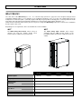
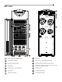
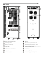
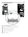
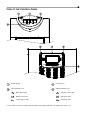
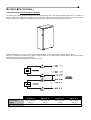
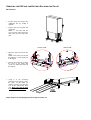
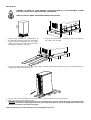
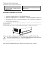
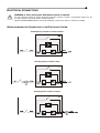
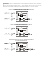
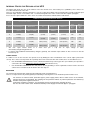
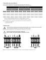
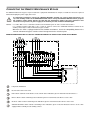
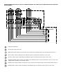
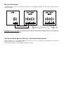
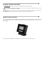
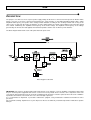
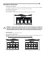
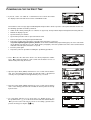
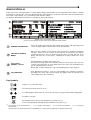
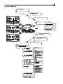
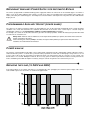
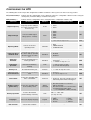
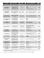
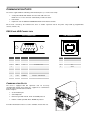
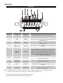
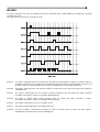
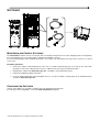
INTRODUCTION
Thank you for choosing our product.
Our company is specialised in designing, developing and manufacturing uninterruptible power supplies (UPS).
The UPS described in this manual is a high quality product which has been carefully designed and built in order to guarantee
the highest levels of performance.
This manual contains detailed instructions for using and installing the product.
For information about using and getting the most out of your appliance, this manual must be stored with care in the
vicinity of the UPS and CONSULTED BEFORE OPERATING ON IT.
NOTE: Some images contained within this document are for indication purposes only and therefore may not identically match
the products in use.
ENVIRONMENTAL PROTECTION
During the development of its products, the company uses extensive resources with regards to all environmental aspects.
All our products pursue the objective defined in the environmental management system developed by the company in
compliance with standards in force.
No hazardous materials such as CFC, HCFC or asbestos are used in this product.
When evaluating packaging, the choice of material has been made favouring recyclable materials.
For correct disposal, please separate and identify the type of material of which the packaging is made in the table below.
Dispose of all material in compliance with standards in force in the country in which the product is used.
DESCRIPTION
MATERIAL
Pallet
Packaging corner
Box
Adhesive pad
Protective bag
Heat-treated pine
Stratocell/cardboard
Cardboard
Stratocell
HD Polyethylene
DISPOSING OF THE PRODUCT
The UPS contains internal material that (in case of dismiss / disposal) are considered TOXIC and HAZARDOUS WASTE, such
as electronic circuit boards and batteries. Treat these materials according to the laws applicable referring to qualified service
personnel. Their proper disposal contributes to respect the environment and human health.
©
The reproduction of any part of this manual, in whole or in part, is forbidden without the prior consent of the manufacturer.
In order to make improvements, the manufacturer reserves the right to modify the product described at any moment and without notice.
CONTENTS
OVERVIEW
5
MULTI SENTRY
5
MCT VIEWS
6
MST VIEWS
7
VIEW OF THE UPS CONNECTIONS
8
VIEW OF THE CONTROL PANEL
9
BATTERY BOX (OPTIONAL)
10
SEPARATE BYPASS INPUT (OPTIONAL)
11
INTERNAL TRANSFORMER
11
ADDITIONAL INTERNAL BATTERY CHARGERS
11
INSTALLATION
STORING THE UPS AND THE BATTERY BOX
PREPARING FOR INSTALLATION
12
12
12
PRELIMINARY INFORMATION
12
ELECTROMAGNETIC COMPATIBILITY
13
INSTALLATION ENVIRONMENT
13
REMOVING THE UPS AND THE BATTERY BOX FROM THE PALLET
14
PRELIMINARY CHECK OF CONTENTS
16
INSTALLING THE UPS AND THE BATTERY BOX
16
STEPS TO BE TAKEN TO GAIN ACCESS TO THE TERMINALS OF THE UPS / BATTERY BOX
16
ELECTRICAL CONNECTIONS
17
WIRING DIAGRAMS FOR CONNECTING TO THE ELECTRICAL SYSTEM
17
INTERNAL PROTECTIVE DEVICES OF THE UPS
20
EXTERNAL PROTECTIVE DEVICES
21
CROSS SECTION OF THE CABLES
22
CONNECTIONS
22
CONNECTIONS OF THE MODEL WITH SEPARATE BYPASS
23
R.E.P.O.
23
EXTERNAL SYNC
23
CONNECTING THE REMOTE MAINTENANCE BYPASS
24
CONNECTING THE BATTERY BOX TO THE UPS
26
MULTIPLE EXPANSIONS
27
SETTING THE RATED BATTERY CAPACITY – SOFTWARE CONFIGURATION
27
EXTERNAL TEMPERATURE PROBE
28
REMOTE PANEL (OPTIONAL)
28
USE
29
DESCRIPTION
29
PRELIMINARY OPERATIONS
30
POWERING ON FOR THE FIRST TIME
31
POWERING ON FROM THE MAINS
32
POWERING ON FROM THE BATTERY
32
POWERING OFF THE UPS
32
GRAPHIC DISPLAY
33
DISPLAY MENUS
34
OPERATING MODES
35
MAINTENANCE BYPASS (SWMB)
35
REDUNDANT AUXILIARY POWER SUPPLY FOR AUTOMATIC BYPASS
36
PROGRAMMABLE AUXILIARY SOCKET (POWER SHARE)
36
POWER WALK-IN
36
REDUCING THE LOAD (TO 200V AND 208V)
36
CONFIGURING THE UPS
37
COMMUNICATION PORTS
39
RS232 AND USB CONNECTORS
39
COMMUNICATION SLOTS
39
AS400 PORT
40
BUZZER
41
SOFTWARE
42
MONITORING AND CONTROL SOFTWARE
42
CONFIGURATION SOFTWARE
42
TROUBLESHOOTING GUIDE
STATUS / ALARM CODES
TECHNICAL DATA
43
47
51
OVERVIEW
MULTI SENTRY
The UPS units of the Multi Sentry 10 – 12 – 15 – 20 kVA range (VFI-SS-111 type) have been designed using the latest
technology available today so as to guarantee users maximum performance. The use of the new control PCBs based on
multiprocessor architecture (DSP + µP inside) together with high frequency IGBT technology offers excellent performance both
in the input stage (absorbed current harmonic distortion ≤ 3%) and in output (output voltage distortion ≤ 1%).
Thanks to these and many other features plus the easy-to-use design, the Multi Sentry represents a new reference standard in
the three-phase UPS sector.
Depending on user requirements, there are two different versions available:
MCT
MST
The Multi Sentry MCT version stands out by its
compact size and new, modern design. These
features make it suitable for any environment.
The Multi Sentry MST version, offers longer
autonomy than the MCT version, thanks to the
possibility to double the number of batteries inside the
cabinet.
10 kVA
12 kVA
15 kVA
20 kVA
10000 VA
9000 W
12000 VA
10800 W
15000 VA
13500 W
20000 VA
18000 W
0.9
0.9
0.9
0.9
MCT
180 Kg
182 Kg
190 Kg
195 Kg
MST
305 Kg
310 Kg
315 Kg
320 Kg
Nominal power
Output power factor
Weight (with
batteries)
MCT
320 x 840 x 930 mm
MST
440 x 850 x 1320 mm
WxDxH
Accessories
Battery cabinets – Communication boards – Remote mimic panel
MCT VIEWS
Battery start button (COLD START)
Brake rod
Manual bypass switch
Slots for accessory communication cards
Battery fuse holder isolator
Communication ports (AS400, USB, RS232)
Output switch
Powershare sockets (10A max. total on the two
sockets) and relative protection
Separate bypass switch (optional)
Ventilation fans
Input switch
Parallel PCB (optional)
Terminal cover panel
1/0 main power switch
MST VIEWS
Battery start button (COLD START)
Brake rod
Manual bypass switch
Slots for accessory communication cards
Battery fuse holder isolator
Communication ports (AS400, USB, RS232)
Output switch
Powershare sockets (10A max. total on the two
sockets) and relative protection
Separate bypass switch (optional)
Ventilation fans
Input switch
Parallel PCB (optional)
Terminal cover panel
Remote Emergency Power Off (R.E.P.O.)
VIEW OF THE UPS CONNECTIONS
Connection for the R.E.P.O command (Remote Emergency Power Off)
(see previous page for the MST version)
Power connections: BATTERY, INPUT, SEPARATE BYPASS (optional), OUTPUT
Connection for remote maintenance bypass command
Connection for external Battery Box temperature probe
Connection for external synchronization signal
Slot for power relay board
VIEW OF THE CONTROL PANEL
Graphic display
Function keys *
Left-hand LEDs area:
Right-hand LEDs area:
Mains power LED
Stand-by / alarm LED
Battery power LED
Battery low LED
Load on bypass LED
ECO mode LED
* The function of each key is indicated at the bottom of the display and varies according to the menu used.
BATTERY BOX (OPTIONAL)
THE BATTERY BOX IS AN OPTIONAL ACCESSORY.
The Battery Box contains batteries that increase the operating time of the UPS during prolonged black-outs. The number of
batteries contained in it will vary according to the type of UPS to which the Battery Box is to be installed. The utmost attention
must be paid to ensure that the battery voltage of the Battery Box corresponds to that supported by the UPS.
Additional Battery Boxes may be connected in a chain to obtain the desired autonomy time during a power failure.
This series of Battery Box contains two separate strings of batteries, one with a positive voltage and the other with a negative
voltage with respect to the neutral terminal (N).
The basic diagram for the Battery Box is shown here below.
Rated voltage
Weight
WxDxH
BBX 1320 480V
BB NP T4 3F
BBX 1320 480V
BB NP T2 3F
BBX 1320 480V
BB NP T8 3F
BBX 1320 480V
BB NP T5 3F
240 + 240 Vdc
240 + 240 Vdc
240 + 240 Vdc
240 + 240 Vdc
300 Kg
390 Kg
395 Kg
400 Kg
400 x 815 x 1320 mm
SEPARATE BYPASS INPUT (OPTIONAL)
THE DI (OPTIONAL) VERSION OF THE UPS SERIES HAS SEPARATE BYPASS AND INPUT LINES.
The UPS series with separate Bypass ensures a separate connection between the input and bypass lines.
The UPS output is synchronised with the bypass line so as to safeguard against incorrect voltage changeovers in the alternate
phases, in the event of automatic bypass or closing of the maintenance switch (SWMB).
INTERNAL TRANSFORMER
THE OT (OPTIONAL) VERSION OF THE UPS SERIES DIFFERS FROM THE STANDARD VERSION IN THAT IT USES AN
ISOLATION TRANSFORMER INSTEAD OF THE BATTERIES.
This series of UPS uses an isolation transformer connected to the UPS output terminals.
NOTE: A separate bypass line is supplied on this UPS version.
The transformer is connected to the UPS output terminals, so the values displayed are those of the quantities
measured upstream of the transformer.
The presence of the transformer inside the UPS modifies the system neutral arrangements.
The installation of a remote maintenance bypass parallel to the UPS is incompatible with inclusion of the transformer.
In any event, if the remote maintenance bypass is inserted, make sure, at the time the remote bypass switch is
closed, that the UPS is isolated from the system by opening the input and/or output switches.
ADDITIONAL INTERNAL BATTERY CHARGERS
THE AC (OPTIONAL) VERSION OF THE UPS SERIES DIFFERS FROM THE STANDARD VERSION IN THAT SOME
ADDITIONAL BATTERY CHARGERS ARE USED INSTEAD OF THE BATTERIES.
This series of UPS must be used together with an external Battery Box and is suitable for applications requiring long back-up
times.
NOTE: A separate bypass line is supplied on this UPS version.
The additional internal battery charger cards are powered directly on mains power and have pseudo-sinusoidal wave form
absorption.
If the input switch is closed but the I/O switch is open (UPS switched off) the battery chargers operate independently.
Open the input switch (SWIN) to totally shutdown the UPS and the additional battery chargers.
AC Version
Nominal voltage
Current in addition to that supplied
by the internal battery charger
10 kVA
12 kVA
15 kVA
240 + 240 Vdc
6A@240Vdc
20 kVA
INSTALLATION
ALL THE OPERATIONS DESCRIBED IN THIS SECTION ARE TO BE PERFORMED EXCLUSIVELY BY
QUALIFIED STAFF.
The company declines all liability for damage caused by incorrect connections or operations not described
in this manual.
STORING THE UPS AND THE BATTERY BOX
The storage room must respect the following conditions:
Temperature:
0°÷40°C (32°÷104°F)
Relative humidity:
max. 95%
PREPARING FOR INSTALLATION
PRELIMINARY INFORMATION
UPS models
10 kVA
12 kVA
15 kVA
20 kVA
Rated power
10000 VA
12000 VA
15000 VA
20000 VA
Working temperature
0 ÷ 40 °C
Max. relative humidity during operation
90 % (non-condensing)
1000 m at rated power
(-1% Power for every 100 m above 1000 m)
max 4000 m
Max. height of installation
WxDxH
320 x 840 x 930 mm
MST
440 x 850 x 1320 mm
MCT
180 Kg
182 Kg
190 Kg
195 Kg
MST
305 Kg
310 Kg
315 Kg
320 Kg
Power dissipated at rated resistive load
(pf=0.9) and with battery as buffer *
0.63 kW
540 kcal/h
2150 B.T.U./h
0.75 kW
645 kcal/h
2560 B.T.U./h
0.86 kW
740 kcal/h
2940 B.T.U./h
1.15 kW
990 kcal/h
3930 B.T.U./h
Power dissipated at rated distortion load
(pf=0.7) and with battery charged *
0.49 kW
420 kcal/h
1670 B.T.U./h
0.58 kW
500 kcal/h
1980 B.T.U./h
0.67 kW
580 kcal/h
2290 B.T.U./h
0.90 kW
775 kcal/h
3070 B.T.U./h
Flow rate of fans for removing heat from
installation room **
340 mc/h
400 mc/h
460 mc/h
615 mc/h
Weight (w/ batteries)
Current leak to earth ***
Isolation protection
Cable input
*
MCT
< 5 mA
IP20
From bottom / on rear
3.97 B.T.U./h = 1 kcal/h
** To calculate the air flow rate, the following formula may be used: Q [m3/h] = 3.1 x Pdiss [Kcal/h] / (ta - te) [°C]
Pdiss is the power expressed in Kcal/h dissipated by all the devices installed in the installation environment.
ta= ambient temperature, te=outside temperature. To take leaks into account, the value obtained should be increased by
10%.
The table shows an example of a flow rate with (ta - te)=5°C and a rated resistive load (pf=0.9).
(Note: This formula is applicable if ta>te, only; if not the UPS installation requires an air-conditioning system).
*** The leakage current of the load is to be added to that of the UPS on the earth wire.
ELECTROMAGNETIC COMPATIBILITY
This UPS product conforms to the current electromagnetic compatibility (EMC) regulations (C2 class). It may cause radio
interference in the home environment. The user may have to adopt supplementary measures.
This product is for professional use in industrial and commercial environments. Connections to USB and RS232 connectors
must be made with the cables provided, or at least with shielded cables less than 3 metres long.
INSTALLATION ENVIRONMENT
When choosing the site in which to install the UPS and the Battery Box, the following points should be taken into consideration:
Avoid dusty environments
Check that the floor is level and capable of withstanding the weight of the UPS and the Battery Box
Avoid cramped environments that could impede the normal maintenance activities
The relative humidity should not exceed 90%, non-condensing
Check that the ambient temperature, with the UPS running, remains between 0 and 40°C
The UPS may be operated with an ambient temperature of between 0 and 40°C. The recommended
working temperature for the UPS and the batteries is between 20 and 25°C. In fact, if the battery has an
average life of 5 years with a working temperature of 20°C, the life is halved if the working temperature is
increased to 30°C.
Avoid installing the equipment in places exposed to the direct sunlight or hot air
To keep the temperature of the installation room within the range indicated above, there must be a system for eliminating the
dissipated heat (the UPS kW / kcal/h / B.T.U./h dissipation values are shown in the table on the previous page). The methods
that may be used are:
Natural ventilation
Forced ventilation, recommended if the outside temperature is less (e.g. 20°C) than the temperature at which the UPS
or Battery Box is to be operated (e.g. 25°C)
Air-conditioning system, recommended if the outside temperature is higher (e.g. 30°C) than the temperature at which
the UPS or Battery Box is to be operated (e.g. 25°C)
REMOVING THE UPS AND THE BATTERY BOX FROM THE PALLET
MCT VERSION
Cut the straps and remove the
cardboard box by sliding it
upwards
Remove the accessory box and
side blocks.
NOTE 1: You will find the
accessory box either inside the
door of the UPS or on top of the
UPS.
FRONT VIEW
Open the door and remove the
slides.
NOTE 2: The slides are fixed to
the pallet by a screw (marked C
in the figure).
Remove the 4 brackets securing
the UPS to the pallet (the
screws are marked A and B in
the figures).
REAR VIEW
B
A
A
C B
A
Using 4 of the previously
removed screws (type A) secure
the slides to the pallet (as
shown). Push the UPS from the
rear off the pallet with great
care. Make sure that the door
is closed before doing this
NOTE: All parts of the packaging should be kept for future use.
B
A
B
A A
A A
MST VERSION
WARNING: IN ORDER TO AVOID DAMAGE TO PERSONS AND/OR TO THE MACHINES, PLEASE
FOLLOW SCRUPULOUSLY THE INDICATIONS GIVEN BELOW.
SOME OF THE FOLLOWING OPERATIONS REQUIRE TWO PEOPLE.
Cut the straps and slide the cardboard box off
the unit pulling upwards. Remove the packaging.
Remove the box containing the accessories.
NOTE: The box of accessories may be inside the
packaging or behind the UPS door.
Remove the two brackets securing the UPS to the pallet by
loosening screws A and B.
Once removed, the two brackets can be used as ramps. Fasten the ramps to the pallet using the screws A and making sure
to align them with the wheels of the unit.
Turn the feet as far as they will go in order to increase the distance between the unit and the pallet.
Make sure that the door is properly closed.
WARNING: to unload the UPS from the pallet, we recommend that you push it down the ramps from behind, taking
every precaution and accompanying the unit along the ramps to the floor. In view of the weight of the machine, this
operation should be carried out by two people.
NOTE: We advise you to keep all the parts of the packaging for future use.
PRELIMINARY CHECK OF CONTENTS
Having opened the package, start by checking the contents.
UPS
BATTERY BOX (optional)
Metal slides, Guarantee document, User manual,
Serial connecting cable, 4 battery fuses (to be
inserted in the "SWBATT" fuse holders), Front door
key (MST version only)
Metal slides, Guarantee document, 4 battery fuses (to be
inserted in the "SWBATT" fuse holders), Front door key
(MST version only)
INSTALLING THE UPS AND THE BATTERY BOX
When installing the equipment, the following points should be considered:
The wheels are to be used exclusively for fine positioning, and thus for small distances only.
The plastic parts and the door are not to be used for gripping or pushing the UPS.
Sufficient space should be left in front of the equipment for it to be turned on/off and maintenance operations to be
performed on it ( ≥ 1.5 mt )
The rear part of the UPS should be set at least 30 cm from the wall, to enable the air blown by the ventilation fans to
flow away correctly
No objects should be left on its top surface
Having set the equipment in position, secure it by engaging the brake rod (see "Front Views of the UPS" point 8) situated below
the connecting terminals.
(MST version only): In seismic areas or for mobile systems, the brackets used to fasten the unit to the pallet (ramps) can be
reused to anchor the UPS to the floor (see the figure below). In normal conditions, the brackets are not necessary.
STEPS TO BE TAKEN TO GAIN ACCESS TO THE TERMINALS OF THE UPS / BATTERY BOX
The operations indicated below are to be performed with the UPS disconnected from the mains powers,
turned off and with all the switches and fuse holders of the equipment open.
Follow the instructions provided below to open the UPS:
Open the door
Remove the terminal and switches cover (see "Views of the UPS" ref. 7)
Having completed the installation operations inside the equipment, replace the terminal cover and close the door.
ELECTRICAL CONNECTIONS
WARNING: a 4-wire three-phase distribution system is required.
The UPS must be connected to a power supply line made up of 3 phases + neutral + PE (protective earth) of TT, TN
or IT type. Therefore, the phase rotation must be respected.
Optional TRANSFORMER BOXES to convert the distribution systems from 3 wires to 4 wires are available.
WIRING DIAGRAMS FOR CONNECTING TO THE ELECTRICAL SYSTEM
UPS without any variation in neutral condition
UPS with galvanic isolation at input
UPS with galvanic isolation at output
UPS without any variation in neutral condition and with separate bypass input
UPS with galvanic isolation and with separate bypass input
UPS with galvanic isolation at output and separate bypass input
Separate bypass:
if the separate bypass option is present, protective devices must be present on both the main power supply line and the bypass
line.
Note: the neutral of the input line and that of the bypass are commoned inside the equipment, so they must refer to the same
potential. If the two power supplies were different, an isolation transformer would have to be used on one of the inputs.
UPS without any variation in neutral condition and with separate bypass input
connected to independent power supply line
UPS with separate bypass input on independent power supply line
and with galvanic isolation at input
UPS with separate bypass input connected to independent power supply line
and with galvanic isolation at output
INTERNAL PROTECTIVE DEVICES OF THE UPS
The table below shows the sizes of the isolators of the UPS and the sizes of the battery fuses (SWBATT): these devices are
accessible from the front of the UPS.
There are also indications about the internal fuses (not accessible) protecting the input and output lines and the maximum input
and rated output currents. To install the UPS, see the block diagram in the “USE” section of the “Description” paragraph.
Fuses are to be replaced with ones of the same size and the characteristics indicated in the table below.
Isolators and internal protective devices
UPS
mod.
Non-automatic switches
Fuses
Input
current
[A] **
Output
current
[A]
Max *
Rated
25A FF 500V
(6.3x32)
20A
15A
32A gG 400V
(10x38)
25A FF 500V
(6.3x32)
24A
17A
2 x 20A FF
500V (6.3x32)
50A gG 400V
(14x51)
2 x 20A FF
500V (6.3x32)
29A
22A
2 x 20A FF
500V (6.3x32)
50A gG 400V
(14x51)
2 x 20A FF
500V (6.3x32)
38A
29A
UPS input /
Separate bypass
UPS output /
Maintenance
SWIN / SWBYP
(optional)
SWOUT / SWMB
10
40A(4P)
40A(4P)
25A FF 500V
(6.3x32)
32A gG 400V
(10x38)
12
40A(4P)
40A(4P)
25A FF 500V
(6.3x32)
15
63A(4P)
63A(4P)
20
63A(4P)
63A(4P)
[kVA]
Rectifier input
fuse
Battery fuse
Output fuse
SWBATT
*
The max. input current refers to a rated load (PF = 0.9) and an input voltage of 346V,
and a battery charger charged with 4A.
** In versions with additional internal battery chargers (optional), the maximum input current on lines L2 and L3 must be
increased by 7A.
SHORT CIRCUIT
If a failure occurs on the load, the UPS protects itself by limiting the value and duration of the current output (short-circuit
current). These values also depend on the operating status of the UPS at the time of the failure; there are two different cases:
2
2
UPS in NORMAL OPERATION: the load is switched instantaneously to the bypass line (I t=11250A s): the input line is
connected to the output without any internal protection (blocked after t>0.5s)
UPS in BATTERY OPERATION: the UPS protects itself by providing a current equivalent to about 1.5 times the rated
current for 0.5s and turns itself off after this time has elapsed
BACKFEED
The UPS has internal protection against backfeed through metal separating devices.
There is an output on the relay board (optional) for activating a releasing device to be installed upstream from the UPS.
The UPS has an internal device (redundant bypass power supply) which, when a failure occurs on the machine,
activates the bypass automatically, thus keeping the load powered without any internal protection and without any
limitation to the power supplied to the load.
Under these emergency conditions, any disturbance present on the input line will affect the load.
See also the “USE” section of the “Redundant Auxiliary Power Supply for Automatic Bypass” paragraph.
EXTERNAL PROTECTIVE DEVICES
MAGNETOTHERMAL
As explained previously, the UPS has protection devices for output faults as well as for internal faults.
In order to set up the power line, install a magnetothermal switch upstream from the UPS with intervention curve B or C. Please
follow the indications in the table below:
Automatic external protective devices
UPS mod.
Mains input
Separate bypass input (optional)
10 kVA
40A
40A
12 kVA
40A
40A
15 kVA
63A
63A
20 kVA
63A
63A
If the protective device upstream from the UPS interrupts the neutral wire, it must also interrupt all the phase wires at
the same time (four-pole switch).
Output protections (recommended values for discrimination)
Normal fuses (GI)
In (Nominal current)/7
In (Nominal current)/7
Normal switches (C curve)
In (Nominal current)/7
In (Nominal current)/7
Ultra-fast fuses (GF)
In (Nominal current)/2
In (Nominal current)/2
DIFFERENTIAL
In versions with no input separation transformer, the neutral from the mains power supply is connected to the UPS output
neutral; as a result, there will be no change to the neutral arrangements of the installation:
THE UPS INPUT NEUTRAL IS CONNECTED TO THE UPS OUTPUT NEUTRAL
THE DISTRIBUTION SYSTEM THAT POWERS THE UPS IS NOT MODIFIED BY THE UPS
The neutral condition is only modified if an isolation transformer is present or when the UPS works with a neutral
isolated upstream.
Make sure that the equipment is connected correctly to the input neutral because as damage may be caused
to the UPS.
During operation with the mains supply present, a differential switch (RCD) at the input to the UPS will activate should a fault
occur on the output side as the output circuit is not isolated from the input circuit.
In any case, other differential switches may still be installed on the output, preferably in coordination with those present at the
input.
The differential switch located upstream must have the following characteristics:
Differential current adjusted to the sum of UPS + Load; we recommend a suitable margin be kept to prevent unwanted
activation (100mA min. - 300mA recommended)
Type B or type A
Delay of at least 0.1s
CROSS SECTION OF THE CABLES
We recommend the INPUT/OUTPUT and BATTERY cables be passed under the UPS.
To determine the minimum cross section of the input and output cables, see the table below:
Cross section of cables (mm2)
INPUT
mains /
separate bypass (optional)
*
BATTERY** (optional)
OUTPUT
kVA
PE
L1/L2/L3
N
PE
L1/L2/L3
N
PE
+/-
N
10
4
2.5
4
4
2.5
4
4
4
4
12
6
4
6
6
4
6
6
6
6
15
6
4
6
6
4
6
6
6
6
20
10
6
10
10
6
10
10
10
10
*
The cross sections indicated in the table refer to a maximum length of 10 metres
**
The maximum length of the cables for connecting the Battery Box (optional) is 3 metres
Note: the maximum cross section of the cables that may be inserted in the terminal board is:
10mm2 for cables with lugs
16mm2 for bare cables
CONNECTIONS
The first wire to be connected is the protective earth wire, which is to be inserted in the terminal marked
PE. During operation the UPS must be connected to the earthing system
Connect the input and output cables to the terminal board as indicated in the figure below:
THE INPUT NEUTRAL MUST ALWAYS BE CONNECTED
DO NOT CONNECT THE OUTPUT NEUTRAL TO THE INPUT NEUTRAL
Note: the connections to the BATTERY module must only be made if the Battery Box (optional) is present.
CONNECTIONS OF THE MODEL WITH SEPARATE BYPASS
The first wire to be connected is the protective earth wire, which is to be inserted in the terminal marked
PE. During operation the UPS must be connected to the earthing system
Connect the input and output cables to the terminal board as indicated in the figure below:
THE INPUT AND BYPASS NEUTRALS MUST ALWAYS BE CONNECTED.
THE INPUT AND BYPASS LINES MUST REFER TO THE SAME NEUTRAL POTENTIAL.
DO NOT CONNECT THE OUTPUT NEUTRAL TO THE INPUT OR BYPASS NEUTRAL.
Note: the connections to the BATTERY module are only to be made if the (optional) Battery Box is present.
R.E.P.O.
This isolated input is used to turn off the UPS remotely in case of emergency.
The UPS is supplied from the factory with the “Remote Emergency Power Off” (R.E.P.O.) terminals short-circuited (see "View of
UPS connections” ref.15). If it is to be installed, remove the short-circuit and connect to the normally closed contact of the stop
device using a cable that provides a double isolation connection.
In case of emergency, by activating the stop device, the R.E.P.O. control is opened and the UPS enters stand-by mode (see
“USE” section), and powers off the load completely.
The R.E.P.O. circuit is self-powered with SELV type circuits. No external power supply voltage is therefore required. When it is
closed (normal condition), a maximum current of 15mA is present.
EXTERNAL SYNC
This non-isolated input is used to synchronise the inverter output with an appropriate signal coming from an external source.
For the installation:
use an isolation transformer with an isolated single-phase output (SELV) comprised in the range 12-24Vac with ≥
0.5VA power
connect the transformer secondary to the "EXTERNAL SYNC" terminal (see "View of UPS connections” ref.19) using a
2
double isolation cable with a 1mm cross-section. Make sure to respect the polarisation as in the figure below.
After installation, enable the control using the configuration software.
CONNECTING THE REMOTE MAINTENANCE BYPASS
An additional maintenance bypass may be installed on a peripheral switchboard, for example, to enable the UPS to be replaced
without interrupting the power supply to the load.
It is absolutely essential to connect the "SERVICE BYPASS" terminal (see "View of UPS connections" ref.
17) to the auxiliary contact of the SERVICE BYPASS switch. Closing the SERVICE BYPASS switch (4) opens
this auxiliary contact which informs the UPS that the maintenance bypass has been activated. If this
connection is not present, the power supply to the load may be shut off and the UPS damaged.
NOTES:
Use cables with a cross section that conforms to the indications given in "Cross Section of the Cables ".
Use a double insulated cable with a cross section of 1mm2 to connect the "SERVICE BYPASS" terminal to the
auxiliary contact of the remote maintenance bypass isolator.
Whenever the UPS is equipped with internal isolation transformer, check the compatibility between the
“remote maintenance bypass” and the neutral arrangement in the electrical plant.
REMOTE MAINTENANCE BYPASS INSTALLATION DIAGRAM ON THE THREE-PHASE-THREE-PHASE MODEL
Peripheral switchboard
Internal connections of the UPS
LINE switch: automatic circuit breaker, must conform to the indications given in "External Protective Devices "
INPUT switch: isolator conforming to the indications given in "Internal Protective Devices of the UPS"
OUTPUT switch: isolator conforming to the indications given in "Internal Protective Devices of the UPS"
SERVICE BYPASS switch: isolator conforming to the indications given in "Internal Protective Devices of the UPS"
equipped with a normally closed auxiliary contact
REMOTE MAINTENANCE BYPASS INSTALLATION DIAGRAM ON THE THREE-PHASE-THREE-PHASE WITH SEPARATE
BYPASS MODEL
Peripheral switchboard
Internal connections of the UPS
MAIN LINE switch: automatic circuit breaker, must conform to the indications given in "External Protective Devices "
INPUT switch: isolator conforming to the indications given in "Internal Protective Devices of the UPS"
OUTPUT switch: isolator conforming to the indications given in "Internal Protective Devices of the UPS"
SERVICE BYPASS switch: isolator conforming to the indications given in "Internal Protective Devices of the UPS"
equipped with a normally closed auxiliary contact
BYPASS LINE switch: automatic circuit breaker, must conform to the indications given in "External Protective Devices "
BYPASS INPUT switch: isolator conforming to the indications given in "Internal Protective Devices of the UPS"
CONNECTING THE BATTERY BOX TO THE UPS
THE CONNECTION BETWEEN THE UPS AND THE BATTERY BOX MUST BE MADE WITH THE DEVICES
POWERED OFF AND UNPLUGGED FROM THE MAINS
UPS POWER-OFF PROCEDURE:
Turn off all devices connected to the UPS or use the remote bypass option (if installed).
Turn off the UPS following the relevant power-off procedure (see the “USE” section of the “Powering off the UPS”
paragraph).
Open all the isolators and fuse holders present in the UPS.
Isolate the UPS completely from the electricity network by opening all the external protective devices situated on the
input and output lines
Wait a few minutes before proceeding to work on the UPS.
Remove the terminal cover of the UPS (see "Operations to access the UPS/Battery Box terminals).
CONNECTING THE BATTERY BOX:
Check that the battery voltage of the Battery Box corresponds to that allowed by the UPS (check the data plate on the
Battery Box and the manual of the UPS)
IMPORTANT: make sure that the fuse holders of the UPS and the Battery Box are open.
Remove the terminal cover of the Battery Box (see "Operations to access the UPS/Battery Box terminals).
Connect the earth terminals of the UPS and the Battery Box using the yellow/green wire of the cable provided.
Connect the terminals to the UPS and the Battery Box:
- terminals marked with the + symbol with the red cable
- terminals marked with the N symbol with the blue cable
- terminals marked with the – symbol with the black cable
respecting the correspondence indicated by the symbols print on the terminal cover of the Battery Box and the UPS.
Reposition the terminal covers removed previously.
CHECKING INSTALLATION:
Insert the fuses in the SWBATT fuse holders of the Battery Box.
Close the SWBATT fuse holders of the Battery Box and the UPS.
Carry out the UPS power-on procedure described in this manual.
After about 30 sec., check that the UPS is working properly: simulate a black-out by opening the SWIN input isolator of
the UPS. The load must continue to be powered, the “battery power” LED must light up on the control panel of the
UPS, and the latter will emit a beep at regular intervals. When the SWIN input isolator is closed again, the UPS must
resume operation on mains power.
MULTIPLE EXPANSIONS
Several Battery Boxes can be connected in a cascade to ensure prolonged autonomy. The connections should be made as
shown here below:
WARNING (only for single UPS): No more than one UPS may be connected to each Battery Box or to more than one
Battery Box connected in a cascade.
SETTING THE RATED BATTERY CAPACITY – SOFTWARE CONFIGURATION
Having installed one or more BATTERY BOXES, the UPS must be set up to update the rated capacity value (total Ah of
batteries inside the UPS + external batteries).
To perform this operation, use the dedicated configuration software.
EXTERNAL TEMPERATURE PROBE
This NON ISOLATED input may be used to measure the temperature inside a remote Battery Box.
The special kit provided by the manufacturers must be used: any methods not conforming to specifications may
cause faults or breakdowns in the equipment.
To install, connect the cable included in the special kit to the "EXT BATTERY TEMP PROBE" connector (see "View of the UPS
Connections" ref. 3).
After installation, enable the outdoor temperature measuring function using the configuration software.
REMOTE PANEL (OPTIONAL)
The remote panel enables the remote monitoring of the UPS and gives a real time detailed summary of the machine status. The
device ensures that the operator can control the electrical values of the mains power, outputs, batteries, etc. and locate any
alarm conditions.
For further information regarding the connection and use of this device, please refer to its apposite manual.
USE
DESCRIPTION
The purpose of a UPS is to ensure a perfect power supply voltage for the devices connected to it irrespective of whether mains
power is present or not. Once connected and powered, the UPS generates a sinusoidal alternating voltage with a stable
amplitude and frequency, irrespective of the changes and/or variations occurring on the electricity network. For as long as the
UPS receives energy from the mains, the batteries are kept charged under the control of the multiprocessor board. This board
also controls continuously the amplitude and frequency of the mains voltage, the amplitude and frequency of the voltage
generated by the inverter, the load applied, the internal temperature and the state of efficiency of the batteries.
The block diagram below shows each of the parts that make up the UPS.
Block diagram of the UPS
IMPORTANT: Our UPS are designed and produced for long life even under the severest conditions. Remember however that
they are electrical power equipment items and as such are in need of periodic checks. Besides, some components have a life
cycle of their own and must therefore be checked at regular intervals and may need to be replaced, where due to the conditions:
in particular, the batteries, fans and in some cases the electrolytic capacitors.
It is recommended to implement a preventive maintenance program, using manufacturer authorised and trained service
personnel.
Our Technical Servicing department is at your disposal to discuss the different personalized preventive maintenance options
with you.
PRELIMINARY OPERATIONS
Visual check of the connection
Check that all the connections have been made strictly following the indications given in the "Connections" paragraph.
Check that the "1/0" button is in its "0" position (see "Front Views of the UPS" point 5).
Check that all the isolators are open.
Close the battery fuse holders
Close the 4 battery fuse holders (SWBATT) present in the position indicated in the figure below.
WARNING: if a battery expansion (Battery Box) has been installed incorrectly (by not following the
information as provided in the "Connecting the Battery Box to the UPS" paragraph) this can lead to the
battery fuses becoming damaged. If this happens, contact the customer services department immediately to
avoid further damage to the UPS. Note: - When the fuses are closed, small arc flashes may occur due to the
charge of the capacitors present inside the UPS. This is normal and does not cause faults and/or damage.
Power on the UPS
Close the protective devices upstream from the UPS.
Close the input and output isolators
Close all the input (SWIN) and output (SWOUT) isolators except for the maintenance isolator (SWMB), which is to
remain open.
Note: if the separate bypass option is present, close also the bypass isolator (SWBYP).
POWERING ON FOR THE FIRST TIME
If present, set the “1/0” switch to “1” and wait for a few seconds. Check that
the display is turned on and the UPS enters "STAND-BY" mode.
Check that no error messages appear indicating that the input cables do not respect the correct phase direction. In this case,
the following operations should be performed:
Switch off the UPS by moving the “I/0” switch to “0” (if present), and open all the input and output disconnecting switches.
Wait for the display to go off.
Open the battery fuse holders.
Open all the protective devices upstream from the UPS
Remove the panel covering the input terminal board
Correct the position of the input wires so that the phase direction is respected.
only if the separate bypass option is present: check which terminal board (input and/or bypass) the error code shown
on the display corresponds to (see the “Alarm Codes” paragraph); correct the position of the wires of the terminal board
indicated so that the phase direction is respected
Close the panel again
Repeat the power-on operations including the "preliminary operations"
Press to enter the start menu. Choose Yes when prompted to confirm.
Press to confirm and wait for a few seconds. Check that the UPS is set
with the load powered by the inverter.
Open the input switch (SWIN) and wait for a few seconds. Check that the
UPS goes into battery-powered mode and that the load is still powered
correctly. A beep should be heard approximately every 7 seconds.
Close the input switch (SWIN) and wait for a few seconds. Check that the
UPS is not in battery-powered mode and that the load is powered correctly
by the inverter.
To set the Date and Time, access menu 8.6.7 (see “Display menus”). Use
the up/down arrows (↑↓) to set the desired value and then confirm with the
key to move to the next field. To save the new settings, go back to the
previous menu by pressing the
key.
POWERING ON FROM THE MAINS
Power the UPS by closing the SWIN input switch and leaving the SWMB maintenance switch open; if present, set the “1/0”
switch to “1”.
After a few moments, the UPS is turned on, the capacitors are precharged and the "Lock / stand-by" LED blinks: The UPS is
in stand-by mode.
Press the button to access the power-on menu. When prompted to confirm, select “YES” and press the button again.
All the LEDs around the display light up for about 1 sec. and a beep is emitted. The message “START UP” appears on the
display to inform the user of the beginning of the start up sequence which ends with transition of the UPS to load powered by
the inverter.
POWERING ON FROM THE BATTERY
If present, set the “1/0” switch to “1”.
Hold the “Cold Start” key down for about 5 seconds. The UPS will start and the display will light up.
Press the button to gain access to the power-on menu. When prompted to confirm, select “YES” and press the again.
All the LEDs around the display light up for about 1 sec. and the buzzer starts to beep once about every 7 seconds.
Note: if the sequence described above is not executed within 1 min., the UPS turns itself off to avoid discharging the batteries
unnecessarily.
POWERING OFF THE UPS
From the main menu, select “OFF” and press to enter the submenu. Then select the option “YES – CONFIRM” and press
. To shut down the UPS completely, set the “1/0” switch (if present) to “0” and open the SWIN input switch.
Note: during prolonged periods of inactivity, it is good practice to shut down the UPS using the “1/0” switch (if
present); open the input and output switches and lastly, with the UPS off, open the battery fuse holders.
GRAPHIC DISPLAY
At the centre of the control panel there is a large graphic display, which provides, in the foreground and in real time, a detailed
overview of the current status of the UPS. Directly from the control panel you can turn the UPS on/off, view the electrical values
(1)
of the mains, output, battery, etc., and make the main machine settings.
The display is divided into four main areas, each with its own specific function.
Sample screens of the graphic display
(screens are only indicative, the data shown may not reflect the actual situation)
GENERAL INFORMATION
Area of the display that shows the date and time permanently, and, depending on the
screen, the page number or the title of the menu currently active.
VIEW DATA / BROWSE
MENUS
Main area of the display used to view the UPS measurements (updated constantly in
real time), and to access the various menus that may be selected by pressing the
relevant function keys. Once the desired menu has been selected, this part of the
display will show one or more pages containing all the data related to the menu
chosen.
UPS STATUS/
ERRORS – FAULTS
Area indicating the operating status of the UPS.
The first line is always active and constantly shows the current status of the UPS; The
second is only active when an error and/or fault occurs on the UPS and indicates the
type of error/fault that has occurred.
On the right, each line indicates the code corresponding to the event in progress.
KEY FUNCTIONS
Area divided into four boxes, each one corresponding to the function key below it.
According to the menu active at that moment, the display shows the function for the
corresponding key in the relevant box.
Key Symbols
To gain access to the main menu
To return to the previous menu or screen
To scroll through the various items on a menu or move from one page to another while viewing data
To confirm a selection
To temporarily silence the buzzer (hold down for more than 0.5 sec.).
To cancel a programmed switching-on/off (hold down for more than 2 sec.)
(1)
The precision of the measurements is:
1% for voltage measurements,
3% for current measurements,
0.1% for frequency
measurements.
The indication of the autonomy time left is an ESTIMATE; so it should not be considered to be a perfectly accurate tool.
DISPLAY MENUS
OPERATING MODES
The mode that guarantees maximum protection for the load is ON LINE mode, in which the energy for the load is converted
twice and is generated perfectly sinusoidal at the output with the frequency and voltage set by the fine digital control of the DSP
irrespective of the input (V.F.I.). *
In addition to the traditional, double-conversion ON LINE operating mode, the following modes may be selected:
ECO (LINE INTERACTIVE)
SMART (SMART ACTIVE)
STBYOFF (STAND-BY OFF)
In order to optimize efficiency, in ECO mode, the load is normally powered from the bypass. If the mains voltage exceeds the
allowed tolerance limits, the UPS switches to normal, double-conversion ON LINE mode. About five minutes after it has
returned within the tolerance limits, the load is switched back to bypass.
If you are not sure which operating mode (ON LINE or ECO) to choose, the UPS may be set in SMART ACTIVE mode in which,
according to statistical data on the quality of the power supply mains, the UPS autonomously decides the mode it is to enter.
Finally, in STAND-BY OFF mode, the UPS is set to operate only in an emergency:
when the mains power is present, the load is powered off while, in the event of a black-out, the load is powered by the inverter
via the batteries, and is then powered off again when mains power is restored. The activation time is less than 0.5 sec.
MAINTENANCE BYPASS (SWMB)
WARNING: Maintenance work inside the UPS is to be performed exclusively by qualified staff. Inside the
UPS there may be a voltage present even when the input, output and battery switches are open. Removal of
the UPS panels by non-qualified staff may result in injury to the operator and damage the equipment.
Below is a list of the operations to be performed in order to carry out maintenance work on the equipment without shutting off
the power supply to the load:
The UPS must power the load via the automatic bypass or the inverter, with the mains voltage present.
N.B.: If the UPS is in battery power mode, activating the maintenance bypass entails shutting off the power supply to
the load.
Close the maintenance bypass isolator (SWMB) situated behind the door: in this way, the input is short-circuited with
the output.
Open the input switches (SWIN), output switches (SWOUT) and battery fuse holders (SWBATT) situated behind the
door: The signal panel is turned off. Wait for the electrolytic capacitors on the power board to discharge (about 15
minutes) and then proceed to perform the maintenance operations.
N.B.: During this phase, with a load powered via the maintenance bypass, any disturbance on the power supply line of
the UPS will affect the devices powered (The load is connected directly to the mains. The UPS is no longer active).
Having completed the maintenance operations, proceed as follows to restart the UPS:
*
Close the input and output isolators, and the battery fuse holders. The signal panel is reactivated. Turn on the UPS
again from the “SYSTEM ON” menu. Wait for the sequence to be completed.
Open the maintenance bypass: the UPS resumes normal operation.
The rms value of the output voltage is set by the fine control of the DSP irrespective of the input voltage while the frequency of the output
voltage is synchronized (within a tolerance range that may be set by the user) with the input voltage to enable the bypass to be used.
Outside this range, the UPS desynchronizes and returns to the rated frequency and the bypass may no longer be used (free running mode).
REDUNDANT AUXILIARY POWER SUPPLY FOR AUTOMATIC BYPASS
The UPS is equipped with a redundant auxiliary power supply that enables the UPS to run on an automatic bypass even when a
failure occurs in the main auxiliary power supply. If a fault occurs in the UPS shutting off the main auxiliary power supply, the
load is powered by the automatic bypass. The multiprocessor board and the control panel are not powered so the LEDs and the
display are off.
PROGRAMMABLE AUXILIARY SOCKET (POWER SHARE)
The UPS has an output socket that enables the load applied to it to be disconnected automatically under certain operating
conditions. The events that determine the automatic disconnection of the Power share socket may be selected using the
configuration software (see the Configuration software and UPS Configuration paragraphs).
For example, the socket can be disconnected after a given time of battery operation, or when the battery low prealarm threshold
is reached or an overload occurs.
Safety notes: when the UPS is switched on, if the output switch (SWOUT) is opened, the Power share socket will
remain connected to the mains.
If the manual bypass switch (SWMB) is inserted, the output switch (SWOUT) is opened and when the UPS is
shutdown, the socket will be disconnected.
POWER WALK-IN
The UPS has a Power Walk-in mode which can be enabled and configured using the configuration software. When the mode is
enabled and mains power is restored after a period of battery operation, the UPS starts to draw progressively from it so as not
to stress (due to the peak) any generating set installed upstream. The transient time may be set from 1 to 125 seconds. The
default value is 10 seconds. During the transient, the necessary power is drawn in part from the batteries and in part from the
mains, maintaining sinusoidal absorption. The battery charger is turned on again once the transient has passed.
REDUCING THE LOAD (TO 200V AND 208V)
If the output voltage is set to 200V and 208V (see “Configuring the UPS” paragraph), the maximum power output of the UPS is
reduced with respect to its rated value, as shown in the graph below:
CONFIGURING THE UPS
The following table shows all possible configurations available to tailor the UPS to your needs in the best way possible.
CP (Control Panel) =
Indicates that the configuration can be edited not only by the configuration software but also using the
control panel (if function editing is enabled on the panel).
SW (Software) =
Indicates that the configuration can be changed from the configuration software only.
FUNCTION
DESCRIPTION
DEFAULT
Output frequency
Selecting the rated output
frequency (for the setting to
be active, turn the UPS off
then back on)
50 Hz
Output Voltage
Selects nominal Output
voltage (Phase / Neutral)
230V
POSSIBLE CONFIGURATIONS
• 50 Hz
• 60 Hz
•
•
•
•
•
•
Operating Mode
Selects one of the 5
operating modes
ON LINE
•
•
•
•
MOD.
CP
200V *
208V *
220V
230V
240V
CP
220 ÷ 240 in steps of 1V
ON LINE
ECO
SMART ACTIVE
STAND-BY OFF
SW
CP
• FREQUENCY CONVERTER
SW
Power off due to
minimum load
Automatically switches off
the UPS in battery operation
when the load is less than
5%
Disabled
• Enabled
• Disabled
CP
Autonomy
limitation
Sets the maximum time of
battery operation
Disabled
• Disabled (complete battery
discharge)
• 1 ÷ 65000 in steps of 1 sec.
SW
Low battery
pre-alarm
Sets the estimated autonomy
time left for low battery
warning
3 min.
1 ÷ 255 in steps of 1 min.
(1 to 7 min from the panel)
SW
Battery test
Sets the interval of time for
the automatic battery test
40 hours
• Disabled/Enabled (from the panel)
• 1 ÷ 1000 in steps of 1 hour
SW
Maximum load
alarm threshold
Selects the user overload
limit
Disabled
• Disabled
• 0 ÷ 103 in steps of 1%
SW
Sound alarm
Selects the operating mode
of the sound alarm
Reduced
• Normal
• Reduced: does not sound because of
momentary intervention of the bypass
CP
• Always connected
• Disconnected after n seconds of
battery operation
• Disconnected after n seconds from the
end-of-discharge alarm signal
• ... (see configuration software manual)
SW
Min.: 0 - Max.: 999
(in steps of 1 Ah)
CP
Auxiliary socket
(power share)
Selects the operating mode
of the auxiliary socket
Always
connected
Battery expansion
Sets the Ah installed
(external battery extension)
0 Ah
Language**
Selects the display language
English
Date and time
Sets the date and time
--
•
•
•
•
English
Italian
German
French
•
•
•
•
--
Spanish
Polish
Russian
Chinese
CP
CP
FUNCTION
DESCRIPTION
DEFAULT
POSSIBLE CONFIGURATIONS
MOD.
Advanced Functions
± 0.25%
± 0.5%
± 0.75%
± 1 ÷ ±10 in steps of 1%
SW
180V
264V
Low:
High:
180 ÷ 220 in steps of 1V
240 ÷ 264 in steps of 1V
SW
200V
253V
Low:
High:
180 ÷ 220 in steps of 1V
240 ÷ 264 in steps of 1V
SW
Input frequency
tolerance
Selects the allowed input
frequency range for
switching to bypass and
for output synchronisation
Bypass voltage
thresholds
Selects the voltage range
allowed for switching to
bypass
Low:
High:
Bypass voltage
thresholds for ECO
Selects the voltage range
allowed for ECO mode
operation
Low:
High:
Activation sensitivity
for ECO
Selects activation
sensitivity during ECO
mode operation
Normal
Power supply of load
in stand-by
Load on bypass power
supply with UPS off
(stand-by status)
± 5%
• Low
• Normal
• High
CP
Disabled (load
NOT powered)
• Disabled (not powered)
• Enabled (powered)
SW
• Enabled / High sensitivity
• Enabled / Low sensitivity
• Disabled with input / output
synchronisation
• Disabled without input / output
synchronisation
SW
• From bypass line
• From external input
SW
• Disabled/Enabled (from the panel)
• 1 ÷ 255 in steps of 1 sec.
SW
• Enabled
• Disabled
SW
Min.: 1 sec. - Max.: 125 sec.
SW
Bypass operation
Selects the bypass line
operating mode
Enabled / High
sensitivity
Inverter
synchronization
(External Sync)
Selects the
synchronisation source
for the inverter output
From bypass line
Start-up delay
Power Walk-In
Duration of Power
Walk-In
Waiting time for automatic
restart after the mains
power supply has been
restored
Enables the mode for
gradual return to mains
power
Sets the duration of the
gradual return to mains
power (only if Power
Walk-in is enabled)
•
•
•
•
5 sec.
Disabled
10 sec.
0.5 Hz/sec
1 Hz/sec
1.5 Hz/sec
2 Hz/sec
SW
• Not enabled
• Enabled
SW
Settings enabled
• Settings enabled
• Settings disabled
SW
Controls enabled
• Controls enabled
• Controls disabled
SW
Speed of
synchronisation
between inverter and
bypass line
Selects the
synchronisation speed
between the inverter and
the bypass line
1 Hz/sec
External temperature
probe (optional)
Enables reading of the
external temperature
probe
Not enabled
UPS settings from
the display
Disable UPS settings
from the display panel
UPS controls from
the display
Disable UPS controls
from the display panel
•
•
•
•
* Once these output voltage values are set, the UPS output power is reduced (see the “Power reduction for 200V and 208V
phase-neutral loads” paragraph)
** Pressing the F1 and F4 keys at the same time for t > 2 sec. automatically resets the language to English.
COMMUNICATION PORTS
The UPS is supplied with the following communication ports (see “Views of the UPS):
Serial port available with RS232 connector and USB connector.
NOTE: the use of one connector automatically excludes the other.
Port AS400
Expansion slots for additional COMMUNICATION SLOT interface boards
On the front, covered by the terminal-cover, there is another expansion slot for the power relay board (4 programmable
contacts, 250Vac, 3A)
RS232 AND USB CONNECTORS
RS232 CONNECTOR
PIN #
NAME
1
TYPE
USB CONNECTOR
SIGNAL
IN
4
3
1
2
PIN #
SIGNAL
1
VBUS
D-
2
TX
OUT
Serial line TX
2
3
RX
IN
Serial line RX
3
D+
4
GND
4
5
GND
6
POWER
OUT
7
8
+15V
POWER
Isolated power supply
15V±5% 80mA max
9
WKATX
OUT
ATX power supply wake-up
COMMUNICATION SLOTS
The UPS is equipped with two expansion slots for accessory
communication boards that enable the equipment to communicate
using the main communication standards.
Some examples:
Second RS232 port
Serial duplicator
Ethernet agent with TCP/IP, HTTP and SNMP protocol
RS232 + RS485 port with JBUS / MODBUS protocol
For further information on the accessories available, visit the web site.
AS400 PORT
AS400 PORT
PIN #
NAME
TYPE
FUNCTION
1
15V
POWER
Isolated auxiliary power supply, +15V±5% 80mA max
15
GND
POWER
Ground to which the isolated auxiliary power supply (15V)
and the remote commands (Remote ON, Remote BYPASS,
Remote OFF) refer
2
REMOTE ON
INPUT #1
When pin 2 is connected to pin 15 for at least 3 seconds, the
UPS is turned on
8
REMOTE OFF
INPUT #2
When pin 8 is connected to pin 15, the UPS is powered off
instantly
7
REMOTE
BYPASS
INPUT #3
When pin 7 is connected to pin 15, the power supply of the
load switches from inverter to bypass. For as long as the
connection remains, the UPS continues to operate from the
bypass even if the input mains voltage is shut off. If the
jumper is removed when the mains voltage is present, the
UPS resumes operation from the inverter. If the jumper is
removed when there is no mains voltage present, the UPS
resumes operation from the battery
4,5,12
BATTERY LOW
OUTPUT #1
Indicates that the batteries are about to run out when
(1)
contact 5/12 is closed
6,13,14
BATTERY
WORKING
OUTPUT #2
Indicates that the UPS is running on battery power when
(1)
contact 6/14 is closed
9,10
LOCK
OUTPUT #3
When the contact is closed, indicates that the UPS is
(1)
locked
3,11
BYPASS
OUTPUT #4
When the contact is closed, indicates that the load is
(1)
powered via the bypass
N.B.: The figure shows the contacts present inside the UPS, capable of carrying a max. current of 0.5A to 42Vdc.
The position of the contacts shown in the figure is with no alarm or signal present.
(1)
The output may be programmed using the configuration software.
The function indicated is selected by default (factory setting)
BUZZER
The status and faults of the UPS are signalled by the buzzer, which will emit a sound modulated according to the operating
conditions of the UPS.
The various kinds of sound are described here below:
Sound A:
The signal is emitted when the UPS is turned on or off using the relevant buttons. A single beep confirms power-on,
activation of the battery test, cancellation of the programmed power-off. When the power-off button is kept pressed,
the buzzer emits the sound A quickly four times, before confirming power-off by emitting a fifth beep.
Sound B:
The signal is emitted when the UPS switches to bypass to compensate for the surge current due to the activation of
a distorting load.
Sound C:
The signal is emitted when the UPS switches to battery operation before the battery low signal (sound D).
Possibility of silencing the report (see paragraph “Graphic Display”)
Sound D:
The signal is emitted during battery operation when the battery low alarm threshold is reached.
Possibility of silencing the report (see paragraph “Graphic Display”)
Sound E:
This signal is emitted in the presence of an alarm or lock.
Sound F:
This signal is emitted if the battery overvoltage fault occurs
Sound G:
This type of signal is emitted when the battery test fails. The buzzer emits ten beeps. The alarm signal is
maintained by the “batteries to be replaced” LED lights up.
SOFTWARE
MONITORING AND CONTROL SOFTWARE
3
The PowerShield software ensures an effective and user-friendly management of the UPS, displaying all the most important
items of information such as the input voltage, load applied and battery capacity.
It can also automatically perform shutdown operations, send e-mails, sms and network messages when specific user-selected
events occur.
Installation operations:
Connect the RS232 communication port of the UPS to a COM communication port of the PC via the serial cable
provided* or connect the USB port of the UPS to a USB port of the PC using a standard USB cable *.
Download the software from www.riello-ups.com, selecting the desired operating system.
Follow the installation program instructions.
For more detailed information about installation and use, refer to the software manual which can be downloaded from
our website www.riello-ups.com.
CONFIGURATION SOFTWARE
Using special software, it is possible to configure the most important UPS parameters.
For a list of possible configurations, refer to the UPS configuration paragraph.
* We recommend the use of a cable no longer than 3 metres.
TROUBLESHOOTING GUIDE
Irregular operation of the UPS is very often not an indication of a fault but is simply caused by simple problems or distractions.
We therefore recommend you consult the table here below, which provides some information that will help you to solve the most
common problems.
WARNING: the table below frequently recommends the use of the maintenance BYPASS. We remind you that
before restoring the UPS to operation, you must make sure that it is on and not in STAND-BY.
If the UPS is in this latter mode, turn on the UPS by accessing the “SYSTEM ON” menu and wait for the power-on
sequence to be completed before removing the maintenance BYPASS.
For further details read the procedures described in the maintenance BYPASS (SWMB) paragraph.
NOTE: For a detailed explanation of the codes listed in the table, see the “STATUS/ALARM CODES” paragraph.
PROBLEM
The UPS WITH THE
MAINS VOLTAGE
PRESENT, DOES NOT
ENTER STAND-BY MODE
(THE RED LOCK/STANDBY LED DOES NOT
BLINK, NO BEEP IS
EMITTED AND THE
DISPLAY IS NOT
TURNED ON)
POSSIBLE CAUSE
SOLUTION
NO CONNECTION WITH
INPUT TERMINALS
Connect the mains to the terminals as indicated in the
installation paragraph
NO NEUTRAL CONNECTION
The UPS cannot work without a neutral connection.
WARNING: If this connection is missing, damage could
be caused to the UPS and/or the load.
Connect the mains to the terminals as indicated in the
Installation paragraph.
1/0 SWITCH BEHIND DOOR IS
SET TO 0
ISOLATOR BEHIND DOOR
(SWIN) IS OPEN
THE UPS RUNS ON
BATTERY POWER EVEN
WHEN THE MAINS
VOLTAGE IS PRESENT
Close the isolator
MAINS VOLTAGE NOT
PRESENT (BLACKOUT)
Check that the mains voltage is present. If necessary,
power on the UPS from the battery to power the load.
PROTECTIVE DEVICE
UPSTREAM ACTIVATED
Reset the protective device. Warning: check that there
is no overload or short-circuit at the output of the UPS.
NO CONNECTION WITH
OUTPUT TERMINALS
Connect the load to the terminals
ISOLATOR BEHIND DOOR
(SWOUT) IS OPEN
THE LOAD IS NOT
POWERED
Set the switch to 1 (if present)
UPS IS IN STAND-BY
Close the isolator
Execute the power-on sequence
STAND-BY OFF MODE IS
SELECTED
The mode must be changed. In fact, STAND-BY OFF
(emergency) mode only powers the loads when a black
out occurs.
UPS FAILURE AND
AUTOMATIC BYPASS OUT OF
ORDER
Insert the maintenance bypass (SWMB) and call your
local service centre
PROTECTIVE DEVICE
UPSTREAM ACTIVATED
Reset the protective device.
WARNING: Check that there is no overload or short
circuit at the output of the UPS.
INPUT VOLTAGE OUTSIDE
TOLERANCE LIMITS FOR
MAINS OPERATION
Problem caused by the mains. Wait for the input mains
voltage to return within the tolerance limits. The UPS
will return automatically to mains operation.
PROBLEM
POSSIBLE CAUSE
SOLUTION
THE DISPLAY SHOWS
C01
THE JUMPER IS MISSING
FROM THE R.E.P.O.
CONNECTOR (J13, REF. 15 “VIEW OF THE UPS
CONNECTIONS”) OR IS NOT
INSERTED CORRECTLY
Assemble the jumper or check that it is inserted
correctly.
MAINTENANCE BYPASS
ISOLATOR (SWMB) CLOSED
Open the isolator (SWMB) situated behind the door.
THE DISPLAY SHOWS
C02
THE DISPLAY SHOWS
ONE OR MORE OF THE
FOLLOWING CODES:
A30, A32, A33, A34
AND THE UPS WILL NOT
START
THE DISPLAY SHOWS
ONE OR MORE OF THE
FOLLOWING CODES:
F09, F10
THE DISPLAY SHOWS
ONE OR MORE OF THE
FOLLOWING CODES:
F11, F14, F15, F16, F17,
L06, L07, L08, L09, L14,
L15, L16, L17, L18, L19,
L20, L21, L22
THE DISPLAY SHOWS
ONE OR MORE OF THE
FOLLOWING CODES:
F03, F04, F05, A08, A09,
A10
THE DISPLAY SHOWS
ONE OR MORE OF THE
FOLLOWING CODES:
F42, F43, F44, L42, L43,
L44
THE JUMPER IS MISSING
FROM THE TERMINALS FOR
THE REMOTE MAINTENANCE
BYPASS (J10, REF. 17 - “VIEW
OF THE UPS CONNECTIONS”)
Insert the jumper
AMBIENT TEMPERATURE
< 0°C
Heat the environment, wait for the heat sink
temperature to rise above 0°C and then start up the
UPS
FAULT IN TEMPERATURE
PROBE ON HEAT SINK
Activate the maintenance bypass (SWMB), turn the
UPS off and on again and exclude the maintenance
bypass. If the problem persists, call your local service
centre
FAULT IN THE INPUT STAGE
OF THE UPS
Activate the maintenance bypass (SWMB), turn the
UPS off and on again. Exclude the maintenance
bypass. If the problem persists, call your local service
centre
PHASE 1 HAS A VOLTAGE
MUCH LOWER THAN THE
OTHER TWO PHASES.
Open SWIN, turn the UPS from the battery, wait for the
end of the sequence and close SWIN
FAULTY LOADS APPLIED
Remove the load. Insert the maintenance bypass
(SWMB), and turn the UPS off and then on again.
Exclude the maintenance bypass. If the problem
persists, call your local service centre
FAULT IN THE INPUT OR
OUTPUT STAGE OF THE UPS
Activate the maintenance bypass (SWMB) and turn the
UPS off and then on again. Exclude the maintenance
bypass. If the problem persists, call your local service
centre
NO CONNECTION ON ONE
OR MORE PHASES
Check the connections to the terminals
INTERNAL PROTECTIVE
FUSES BLOWN ON THE
PHASES OR INPUT RELAY
BROKEN
Call your local service centre
THE INTERNAL PROTECTION
FUSES ON THE BATTERIES
HAVE BLOWN
Call the nearest service centre.
PROBLEM
POSSIBLE CAUSE
SOLUTION
PROTECTIVE DEVICE
UPSTREAM FROM THE
BYPASS LINE OPEN (ONLY IF
BYPASS IS SEPARATE)
Reset the protective device upstream. WARNING:
check that there is no overload or short circuit at the
output of the UPS
BYPASS ISOLATOR OPEN
(SWBYP ONLY IF BYPASS IS
SEPARATE)
Close the isolator situated behind the door.
THE DISPLAY SHOWS
ONE OR MORE OF THE
FOLLOWING CODES:
F19, F20
BATTERY CHARGER FAULT
Open the battery fuse holders (SWBATT), insert the
maintenance bypass (SWMB) and shut down the UPS
completely. Switch on again and if the fault persists,
contact the nearest technical support centre.
THE DISPLAY SHOWS
ONE OR MORE OF THE
FOLLOWING CODES:
A26, A27
BATTERY FUSES BLOWN OR
FUSE HOLDER ISOLATORS
OPEN
Replace the fuses or close the isolators (SWBATT).
WARNING: if necessary, we recommend fuses be
replaced with others of the same type (see Internal
Protective Devices of the UPS)
THE DISPLAY SHOWS
THE CODE S06
THE BATTERIES ARE
DISCHARGED; THE UPS
WAITS FOR THE BATTERY
VOLTAGE TO EXCEED THE
THRESHOLD SET
Wait for the batteries to recharge or force power on
from the System On menu
THE DISPLAY SHOWS
ONE OR MORE OF THE
FOLLOWING CODES:
F06, F07, F08
INPUT RELAY LOCKED
Activate the maintenance bypass (SWMB), turn off the
UPS, open SWIN and call your local service centre.
THE DISPLAY SHOWS
ONE OR MORE OF THE
FOLLOWING CODES:
A13, A14, A15
FAULT IN:
THE DISPLAY SHOWS
ONE OR MORE OF THE
FOLLOWING CODES:
L01, L10, L38, L39, L40,
L41
THE DISPLAY SHOWS
ONE OR MORE OF THE
FOLLOWING CODES:
A22, A23, A24, F23, L23,
L24, L25
THE DISPLAY SHOWS
ONE OR MORE OF THE
FOLLOWING CODES:
L26, L27, L28
TEMPERATURE
PROBE OR UPS
COOLING SYSTEM
MAIN AUXILIARY
POWER SUPPLY
STATIC BYPASS
SWITCH
Activate the maintenance bypass (SWMB), turn the
UPS off and then on again. Exclude the maintenance
bypass. If the problem persists, call your local service
centre
THE LOAD APPLIED TO THE
UPS IS TOO HIGH
Reduce the load to below the 100% threshold (or user
threshold for the code A22, A23 or A24)
SHORT CIRCUIT AT OUTPUT
Power off the UPS.
Disconnect all the devices connected to the phase
concerned by the short circuit.
Power menu the UPS on again.
Reconnect the devices one by one until the faulty one is
identified.
PROBLEM
POSSIBLE CAUSE
SOLUTION
THE DISPLAY SHOWS
ONE OR MORE OF THE
FOLLOWING CODES:
A39, A40
AND THE RED
“BATTERIES TO BE
REPLACED” LED IS ON
THE BATTERIES HAVE
FAILED THE PERIODIC
EFFICIENCY TEST
The batteries of the UPS should be replaced in that
they are no longer able to maintain the charge for a
sufficient time to ensure the required autonomy.
Warning: The batteries are to be replaced by
qualified staff
THE DISPLAY SHOWS
ONE OR MORE OF THE
FOLLOWING CODES:
F34, F35, F36, L34, L35,
L36
AMBIENT TEMPERATURE
OVER 40°C
HEAT SOURCES CLOSE
TO THE UPS
VENTILATION SLITS
OBSTRUCTED OR TOO
CLOSE TO WALLS
FAULT IN TEMPERATURE
PROBE OR UPS COOLING
SYSTEM
THE DISPLAY SHOWS
ONE OR MORE OF THE
FOLLOWING CODES:
F37, L37
THE DISPLAY SHOWS
ONE OR MORE OF THE
FOLLOWING CODES:
L11, L12, L13
AMBIENT TEMPERATURE
IS OVER 40°C
HEAT SOURCES CLOSE
TO THE UPS
VENTILATION SLITS
OBSTRUCTED OR TOO
CLOSE TO WALLS
FAULT IN THE
TEMPERATURE PROBE
OR BATTERY CHARGER
COOLING SYSTEM
Activate the maintenance bypass (SWMB) without
powering off the UPS; in this way, the fans cool the
heat sink more quickly. Eliminate the cause of the
overtemperature and wait for the temperature of the
heat sink to drop. Exclude the maintenance bypass.
Insert the maintenance bypass (SWMB) without turning
off the UPS so that the fans, continuing to run, cool the
heat sink more quickly and wait for the temperature of
the heat sink to drop. Turn the UPS off and then on
again. Exclude the maintenance bypass. If the problem
persists, call your local service centre
Eliminate the cause of the overtemperature.
Open the battery fuse holder isolators (SWBATT) and
wait for the temperature of the battery charger heat sink
to drop.
Close the battery fuse holders. If the problem recurs,
call your local service centre. WARNING: never open
the SWBATT fuse holders during battery operation.
BREAKDOWN OR
MALFUNCTIONING OF
THE STATIC BYPASS
Activate the maintenance bypass (SWMB), switch the
UPS off and then on again. Exclude the maintenance
bypass. If the fault persists, contact the nearest
technical support centre
THE DISPLAY SHOWS
NOTHING OR PROVIDES
INCORRECT
INFORMATION
THE DISPLAY HAS POWER
SUPPLY PROBLEMS
Activate the maintenance bypass (SWMB), shut down
the UPS completely and wait for a few seconds.
Switch the UPS on again. Exclude the maintenance
bypass. If the problem persists, contact the nearest
technical support centre.
THE DISPLAY IS OFF,
THE FANS ARE OFF BUT
THE LOAD IS POWERED
DUE TO A FAULT IN THE
AUXILIARIES, THE UPS IS IN
BYPASS SUPPORTED BY THE
REDUNDANT POWER SUPPLY
Activate the maintenance bypass (SWMB), shut down
the UPS completely and wait for a few seconds. Try to
switch on again.
If the display does not light up or the sequence fails,
contact the nearest technical support centre and leave
the UPS in manual bypass mode.
STATUS / ALARM CODES
Using a sophisticated self-diagnostic system, the UPS can check and indicate on the display panel its status and any errors
and/or faults that have occurred during its operation. When a problem arises, the UPS signals the event by showing the code
and corresponding type of alarm on the display.
Status: indicates the current status of the UPS.
CODE
DESCRIPTION
S01
Precharging
S02
Load not powered (stand-by status)
S03
Power-on phase
S04
Load powered by bypass line
S05
Load powered by inverter
S06
Battery operation
S07
Waiting for batteries to recharge
S08
Economy mode enabled
S09
Ready for power on
S10
UPS locked – load not powered
S11
UPS locked – load on bypass
S12
BOOST stage or battery-charger locked – load not powered
S13
Frequency converter - load powered by inverter
Command: indicates that a command has been activated.
CODE
DESCRIPTION
C01
Remote power-off command
C02
Remote load on bypass command
C03
Remote power-on command
C04
Battery test running
C05
Manual bypass command
C06
Emergency power-off command
C07
Remote battery charger power-off command
C08
Load on bypass command
Warning: messages that refer to a specific configuration or operation of the UPS.
CODE
DESCRIPTION
W01
Battery low warning
W02
Programmed power-off enabled
W03
Programmed power-off command imminent
W04
Bypass disabled
W05
Synchronization disabled (UPS in Free running mode)
Anomaly: “minor” problems that do not bring the UPS to a halt but affect its performance or inhibit the use of some of
its functions.
CODE
DESCRIPTION
A03
Inverter Desynchronized
A04
External synchronism failed
A05
Overvoltage on input line of Phase1
A06
Overvoltage on input line of Phase2
A07
Overvoltage on input line of Phase3
A08
Undervoltage on input line of Phase1
A09
Undervoltage on input line of Phase2
A10
Undervoltage on input line of Phase3
A11
Input frequency outside tolerance limits
A13
Voltage on bypass line of Phase1 outside tolerance limits
A14
Voltage on bypass line of Phase2 outside tolerance limits
A15
Voltage on bypass line of Phase3 outside tolerance limits
A16
Bypass frequency outside tolerance limits
A18
Voltage on bypass line out of range
A19
Overcurrent peak on output Phase 1
A20
Overcurrent peak on output Phase2
A21
Overcurrent peak on output Phase 3
A22
Load on Phase1 > user-defined threshold
A23
Load on Phase2 > user-defined threshold
A24
Load on Phase3 > user-defined threshold
A25
Output isolator open
A26
Positive branch batteries missing or battery fuses open
A27
Negative branch batteries missing or battery fuses open
A29
System temperature probe faulty
A30
System temperature < 0°C
A31
System temperature too high
A32
Temperature of heat sink 1 < 0°C
A33
Temperature of heat sink 2 < 0°C
A34
Temperature of heat sink 3 < 0°C
A35
Internal battery temperature probe faulty
A36
Internal battery overtemperature
A37
External battery temperature probe faulty
A38
External battery overtemperature
A39
Positive branch batteries to be replaced
A40
Negative branch batteries to be replaced
Fault: more critical problems than “Anomalies” in that, if they persist, they may bring the UPS to a halt.
CODE
DESCRIPTION
F01
Internal communication error
F02
Incorrect input phase direction.
F03
Input fuse of Phase1 broken or input relay blocked (will not close)
F04
Input fuse of Phase 2 broken or input relay blocked (will not close)
F05
Input fuse of Phase3 broken or input relay blocked (will not close)
F06
Input relay of Phase1 blocked (always closed)
F07
Input relay of Phase2 blocked (always closed)
F08
Input relay of Phase3 blocked (always closed)
F09
Precharge of positive branch capacitors failed
F10
Precharge of negative branch capacitors failed
F11
BOOST stage anomaly
F12
Incorrect bypass phase direction.
F14
Sine wave of inverter phase1 distorted
F15
Sine wave of inverter phase2 distorted
F16
Sine wave of inverter phase3 distorted
F17
Inverter stage anomaly
F19
Positive battery overvoltage
F20
Negative battery overvoltage
F21
Positive battery undervoltage
F22
Negative battery undervoltage
F23
Overload at output
F26
Output relay of Phase1 blocked
F27
Output relay of Phase2 blocked
F28
Output relay of Phase3 blocked
F29
Output fuse of Phase1 blown
F30
Output fuse of Phase2 blown
F31
Output fuse of Phase3 blown
F32
Battery charger stage anomaly
F33
Output fuse of battery charger blown
F34
Heat sink overtemperature
F37
Battery charger overtemperature
F42
BOOST battery 1 fuse blown
F43
BOOST battery 2 fuse blown
F44
BOOST battery 3 fuse blown
Lock: indicate a breakdown of the UPS or one of its parts. Locks are normally preceded by an alarm signal. In the
event of a fault and resultant breakdown of the inverter, the inverter will be switched off and the load will be powered by
the bypass line (this procedure is excluded for breakdowns caused by high and persistent overloads and by short
circuits).
CODE
DESCRIPTION
L01
Incorrect auxiliary power supply
L02
One or more internal cables disconnected
L03
Phase 1 input fuse broken or input relay locked (will not close)
L04
Phase 2 input fuse broken or input relay locked (will not close)
L05
Phase 3 input fuse broken or input relay locked (will not close)
L06
BOOST stage overvoltage positive
L07
BOOST stage overvoltage negative
L08
BOOST stage undervoltage positive
L09
BOOST stage undervoltage negative
L10
Static bypass switch fault
L11
L1 bypass output breakdown
L12
L2 bypass output breakdown
L13
L3 bypass output breakdown
L14
Phase1 inverter overvoltage
L15
Phase2 inverter overvoltage
L16
Phase3 inverter overvoltage
L17
Phase1 inverter undervoltage
L18
Phase2 inverter undervoltage
L19
Phase3 inverter undervoltage
L20
Direct voltage at output of inverter or Sine wave of Phase1 inverter distorted
L21
Direct voltage at output of inverter or Sine wave of Phase2 inverter distorted
L22
Direct voltage at output of inverter or Sine wave of Phase3 inverter distorted
L23
Overload at output of Phase1
L24
Overload at output of Phase2
L25
Overload at output of Phase3
L26
Short circuit at output of Phase1
L27
Short circuit at output of Phase2
L28
Short circuit at output of Phase3
L29
Phase 1 output fuse broken or output relay locked (will not close)
L30
Phase 2 output fuse broken or output relay locked (will not close)
L31
Phase 3 output fuse broken or output relay locked (will not close)
L34
Heat sink Phase 1 overtemperature
L35
Heat sink Phase 2 overtemperature
L36
Heat sink Phase 3 overtemperature
L37
Battery charger overtermperature
L38
Temperature probe of heat sink Phase 1 faulty
L39
Temperature probe of heat sink Phase 2 faulty
L40
Temperature probe of heat sink Phase 3 faulty
L41
Temperature probe of battery charger faulty
L42
BOOST battery 1 fuse blown
L43
BOOST battery 2 fuse blown
L44
BOOST battery 3 fuse blown
TECHNICAL DATA
UPS Models
10 kVA
12 kVA
15 kVA
20 kVA
Input stage
Rated voltage
380-400-415 Vac Three-phase with neutral (4 wires)
Rated frequency
50-60Hz
Accepted tolerance for input voltage without
activation of battery (for 400Vac)
±20% @ 100% load
-40% +20% @50% load
Accepted tolerance for input frequency without
activation of battery (for 50/60Hz)
±20%
40-72Hz
IGBT high frequency with PFC control, independent digital average current mode on
each input phase
Technology
Input current harmonic distortion
THDi ≤ 3 %
Input power factor
(7)
≥0.99
Power Walk-in
Programmable from 5 to 30 sec. in steps of 1 sec.
Output stage
Rated voltage
(1)
Rated frequency
380/400/415 Vac Three-phase with neutral (4 wires)
(2)
50/60Hz
Rated apparent output power
Rated active output power
10kVA
12kVA
15kVA
20kVA
9kW
10.8kW
13.5kW
18kW
Output power factor
0,9
Short circuit current
1,5x In for t>500ms
Precision of output voltage (with respect to output
voltage 400Vac)
Static stability
(3)
± 1%
± 0.5%
Dynamic stability
± 3% resistive load
Output voltage harmonic distortion with
standardized linear and distorting load
Crest factor allowed at rated load
Precision of frequency in free running mode
Inverter overloads @ PFout = 0.8
(Resistive load)
Inverter overloads @ PFout = 0.9
(Resistive load)
Bypass overload
(4)
≤1% with linear load
≤3% with distorting load
3:1
0.01%
115% continuously
125% 10 min
150% 1 min
168% 5 sec
>168% 0.5 sec
110% 10 min
133% 1 min
150% 5 sec
>150% 0.5 sec
110% continuously
133% 60 minutes
150% 10 minutes
>150% 2 sec
IGBT high frequency with multiprocessor digital control (DSP+µP), voltage/current
based on signal processing methods with feed forward
Technology
Battery charger stage
Rated voltage
Maximum recharging current
±240Vdc
(5)
Battery charger algorithm
Technology
Tolerance of input voltage for recharging at
maximum current
6A
Two levels with temperature compensation
Analogue switching current mode under the control of the µP
(PWM regulation of charging voltage and current)
345-480Vac
UPS Models
10 kVA
12 kVA
15 kVA
20 kVA
Dimensions and weight
MCT
320 x 840 x 930 mm
MST
440 x 850 x 1320 mm
WxDxH
MCT
80 Kg
82 Kg
90 Kg
95 Kg
MST
105 Kg
110 Kg
115 Kg
120 Kg
MCT
180 Kg
182 Kg
190 Kg
195 Kg
MST
305 Kg
310 Kg
315 Kg
320 Kg
Weight without batteries
Weight with batteries
Modes and efficiency values
True on line double conversion
ECO mode
Smart Active mode
Stand-by Off (Emergency)
Frequency Converter
Operating modes
AC/AC efficiency in on line mode
≥93.5%
≥94%
AC/AC efficiency in Eco mode
≥98%
DC/AC efficiency in autonomy mode
≥92.5%
≥93.5%
≤48dB(A)
≤52dB(A)
Miscellaneous
Noise
Color
Ambient temperature
(1)
(2)
(3)
(4)
(5)
(6)
(7)
RAL 7016
(6)
0 – 40 °C
To maintain the output voltage within the range of precision indicated, it may have to be recalibrated after a long period of operation
If the mains frequency is within ± 5% of the selected value, the UPS is synchronized with the mains. If the frequency is outside the
tolerance limits or running on the battery, the frequency is the value selected +0.1%
Mains/Battery @ load 0% -100%
@ Mains / battery / mains @ resistive load 0% / 100% / 0%
The recharging current is regulated automatically according to the capacity of the battery installed
20 – 25 °C for maximum battery life
@ 100% load & THDv ≤ 1%
Battery Box
BBX 1320 480V
BB NP T4 3F
BBX 1320 480V
BB NP T2 3F
80 / 12 / 9
120 / 12 / 7
BBX 1320 480V
BB NP T8 3F
BBX 1320 480V
BB NP T5 3F
80 / 12 / 12
120 / 12 / 9
Battery
Rated voltage per branch
No. batteries / V / Ah
240 Vdc
Miscellaneous
Ambient temperature
(1)
0 – 40 °C
Humidity
<95% non-condensing
Protective devices
Overcurrent – Short circuit
WxDxH
Weight
(1)
20 – 25 °C for maximum battery life
400 x 815 x 1320 mm
300 Kg
390 Kg
395 Kg
400 Kg
0MNMSTK10RU5LUA