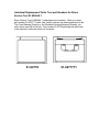
1
Table Of Contents
Section 1 - Fuel Systems
Section 2 - Electrical Systems
Section 3 - Exhaust and Cooling Systems
Section 4 - Transom Assemblies
Section 5 - Sterndrives
Section 6 - Customer Satisfaction Index
2005_MerCruiser_Product_Update (0804)
1
2005
Product Update
Section 1
Fuel Systems
Table of Contents
496 Mag & 8.1S Calibrations that Reduce the Amount of Soot
Produced
Mercury MerCruiser Engine Emission Regulations Changes Effective
January 1, 2003.
MerCruiser U.S. advertised engine power rating
2002 Built Carbureted Engines with Sealed Idle Mixture Screws.
Electric Fuel Pump Troubleshooting
Quad-Rings and O-Rings for Fuel Pressure Gauge Schrader Valve
Adaptor Kit, P/N 91-803135.
Turn Key Start (TKS) Carburetor
MEFI III to IV Conversion Kits
Cool Fuel III EFI System
Digital Diagnostic Terminal (DDT) Cartridge - 1.31 Version
Computer Diagnostic System (CDS)
496 Mag & 8.1S Calibrations that Reduce the Amount of Soot
Produced
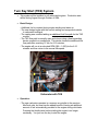
There have been complaints of MCM 496 MAG and MIE 8.1s units, both Base
and H.O., causing soot deposits on boats. A new calibration has been released
that significantly reduces the amount of soot produced. These calibrations will be
available through P&A in replacement PCM's.
Whether, or not, a boat will develop soot deposits is very much dependent on the
boat design, especially the exhaust locations and transom configuration. Boats
with molded swim platforms with thru-transom exhaust exiting below the swim
platform, are most likely to experience sooting. This is because a low pressure
area develops beneath the swim platform, when the boat is moving, which holds
the exhaust in this area and allows it to settle on the boat surfaces. This "station
wagon" effect in some boats has also caused soot to settle on the top side of the
swim platform, on the engine cover/sun deck and on other surfaces. If a
customer's boat, with a 496 Mag/8.1S engine, has this problem then contact
MerCruiser Service.
The next page shows the before and after view of a boat that had this sooting
problem. The calibration change made a 70-80% improvement in this condition.
It is recommend to use a cleaning product called Castrol Super Clean when
cleaning the boat. Some cleaning products, such as wax and PowerTune, leave
a residue that promotes the formation of soot deposits. Castrol Super Clean has
been found to not leave such a residue, and will remove the residue left by
previous cleaning products.
496/8.1 Engine Soot Update
• A twin 496/8.1L HO in a 33 Foot Boat, after 15 minutes at WOT.
Old Cal
New Cal
Mercury MerCruiser Engine Emission Regulations Changes Effective
January 1, 2003.
The changes that become effective January 1, 2003, regarding emission regulations, pertain to
all Mercury MerCruiser gas Sterndrives, Inboards and Tow Sports models, as well as the
Scorpion 377 and HP500 EFI Racing Sterndrive (hereafter referred to as MerCruiser engines)
certified to California emissions standards.
All MerCruiser engines (500 hp and below) with a production date of January 1, 2003, or later
are factory-certified to meet the California Air Resources Board’s (CARB) 2003 exhaust
emission standards. Each factory-certified engine includes a Consumer Information Hang Tag
and two California three-star labels, one on the engine and one with instructions for proper
installation by the boat builder on MerCruiser-powered boats. The star label is required by the
State of California to be affixed to the hull per their guidelines.
Dealers in CA, AZ, NV and OR received further information found below:
Please note that MerCruiser engines built prior to January 1, 2003 do not require CARB
certification and may be sold without restriction. Specifically, MerCruiser engines in your
inventory that were built prior to the effective date do not require certification (three-star label)
and may be sold in California. Also note that the HP900 SC Dry-Sump, HP575 SCi and the
HP525 EFI Mercury Racing Sterndrive engines do not require certification and may be sold in
California.
The length of warranty coverage on certain components considered as emissions related
components by California CARB certification is also different.
All carburetors on 3.0L, 4.3L, 5.0L and 5.7L engines, boxed after 1.Jan 2003, have a sealed idle
mixture screw.
The idle mixture screw adjustment is strictly regulated by CARB. However, if the carburetor is
overhauled, CARB allows the adjustment of the mixture screw back to original specifications.
The idle mixture screw is located under the sealed cap. After the overhaul, install a new Tamper
Proof Idle Mixture Screw Kit, leaving the cap off. Adjust the idle mixture screw back to the
original factory specified 'turns out' (see reference list below), then install the tamper proof
sealing cap.
NOTE: Access to the idle mixture screw can only be made by removing the seal. The sealing
cap can be removed by carefully cutting both sides of the outer seal. Use a screwdriver to pry
the outer seal apart at the cuts until you can get the cap out. It is recommended that additional
Tamper Proof Idle Mixture Screw Kits be ordered for stock because the original seal will be
damaged during the removal process.
P/N 3302-803930 Tamper Proof Idle Mixture Screw Kit. (Kit includes a new idle mixture screw,
spring, seal cup and seal cap).
3.0L: P/N 3310-864940A01 w/sealed idle mixture screw:
4.3L: P/N 3310-864941A01 w/sealed idle mixture screw:
5.0L: P/N 3310-864942A01 w/sealed idle mixture screw:
5.7L: P/N 3310-864943A01 w/sealed idle mixture screw:
Screw set at 1-1/2 turns out.
Screw set at 1-1/4 turns out.
Screw set at 1-1/2 turns out.
Screw set at 1-1/2 turns out.
NOTE: The carburetor P/N listed is the complete replacement service carburetor that must be
used on engines built after January 1, 2003.
MerCruiser U.S. advertised engine power rating
Also, effective January 1, 2003 MerCruiser U.S. advertised engine power rating will be based on
crankshaft rather than propshaft measurement. We will continue to use the same SAE
J1228/ISO 3046 rating protocol that we use now, which allows for either form of rating. The
rated horsepower will not change from the current values since both methods of rating may yield
similar values within the tolerances specified by the standard. Unlike outboards, a MerCruiser
engine may be associated with a number of transmission devices and the propshaft power will
vary depending on the specific type of transmission involved. By rating power at the crankshaft,
Mercury better defines for customers the engine that powers their vessel, regardless of the
nature of the specific propulsion system involved.
This new hp rating location is in all new owner’s manuals and consumer literature.
2002 Built Carbureted Engines with Sealed Idle Mixture Screws.
Because of the labor strike on the West Coast of the USA last year, shipments of MerCarbs for
the 2002 3.0L and 4.3L were delayed. To fill engine orders during this time period, the engines
listed below were assembled with a California CARB carburetor on them. This carburetor has a
sealed idle mixture screw. If the dealer needs to check the idle mixture screw setting, the seal
will have to be cut off. In most cases, the 3.0L MerCarb will not have to be removed. The V6
MerCarb will have to be removed from the engine to cut the seal off.
The sealing cap can be removed by carefully cutting both sides of the outer seal. Use a
screwdriver to pry the outer seal apart at the cuts until you can get the cap out.
Because these engines were built in 2002, the seal does not have to be reinstalled. If the idle
mixture screw is damaged during the removal of the seal, install a new idle mixture screw.
2002 Engines with sealed California CARB carburetors on them:
3.0L:
S/N 0M382941- 0M3845400 built 11-21-2002.
S/N 0M384660 - 0M384960 built 12-5-2002.
4.3L:
0M620455 - 0M622544 built 11-22-2002.
b
6HUYLFH%XOOHWLQ
:DUUDQW\,QIRUPDWLRQ
6HUYLFH,QIRUPDWLRQ
%XOOHWLQ1Rb
3DUWV,QIRUPDWLRQ
&LUFXODWHWR
6DOHV0DQDJHU
$FFRXQWLQJ
6HUYLFH0DQDJHU
7HFKQLFLDQ
3DUWV0DQDJHU
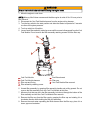
(OHFWULF)XHO3XPS7URXEOHVKRRWLQJ
0RGHOV$IIHFWHG
$OO0HU&UXLVHU9DQG9FDUEXUHWRU(),DQG03,JDVHQJLQHV
6LWXDWLRQ
0HUFXU\ 0HU&UXLVHU UHFHLYHV HOHFWULF IXHO SXPSV UHWXUQHG IRU ZDUUDQW\ WKDW IXQFWLRQ
SURSHUO\ZKHQWHVWHG1R7URXEOH)RXQG
(QJLQHV WKDW DUH QRW UXQ IRU H[WHQGHG SHULRGV RI WLPH RU DUH SODFHG LQ VWRUDJH ZLWK
XQWUHDWHGIXHODUHDWULVNRIIRUPLQJIXHOJXP7KHDFFXPXODWLRQRIIXHOJXPFDQVHL]H
HOHFWULF IXHO SXPSV ZKLFK W\SLFDOO\ UHVXOWV LQ WKH UHSODFHPHQW RI D PHFKDQLFDOO\ VRXQG
IXHOSXPS
127(%RRVWSXPSVXVHGRQ(),RU03,PRGHOVDUHWKHVDPHORZSUHVVXUHSXPSXVHG
RQFDUEXUHWHGPRGHOV7KHSXPSVXVHGWRSUHVVXUL]HWKH(),RU03,V\VWHPLVDKLJK
SUHVVXUHSXPS
,03257$17(OHFWULFIXHOSXPSFDQEHUXQGU\IRUVHFRQGV'RQRWUXQWKHSXPSGU\
UHSHDWHGO\RULQWHUQDOGDPDJHPD\RFFXU
$ORWFDQEHOHDUQHGE\SXWWLQJ\RXUKDQGRQWKHIXHOSXPSZKHQYROWDJHLVDSSOLHGWRWKH
SXPS
,I WKH SXPS GRHV QRW UXQ EXW IHHOV OLNH D VROHQRLG FORVLQJ ZKHQ EDWWHU\ YROWDJH LV
DSSOLHGLWLVORFNHGXS,QPRVWFDVHVWKHSXPSLVORFNHGXSEHFDXVHRIIXHOJXPDQG
FDQEHIUHHGE\GRLQJWKHIROORZLQJ
D /HDYHWKHSXPSIXOORIDPL[WXUHRIIUHVKJDVROLQHDQG)XHO6\VWHP7UHDWPHQW
DQG6WDELOL]HURYHUQLJKW
E 8VHPL[WXUHDVRXWOLQHGLQWKHIRJJLQJSURFHGXUHLQ0HU&UXLVHU6HUYLFH%XOOHWLQ
,03257$17 'R QRW XVH WKH )676 FRQFHQWUDWH ZKHQ GRLQJ WKLV 2WKHU IXHO V\VWHP
FRPSRQHQWVWKDWPD\EHJXPPHGXSVKRXOGEHWUHDWHGZLWKWKLVVDPHPL[WXUH
F 8VHPOIOR]RIWKH)676SHU/86JDORIIXHOIRUWKHQH[W/
86JDORIIXHOXVHGLQWKHHQJLQH
7+(,1)250$7,21,17+,6'2&80(17,6&21),'(17,$/$1'3527(&7('%<&23<5,*+7$1',67+(3523(57<2)0(5&85<0$5,1(
7KLVGRFXPHQWLVSURYLGHGIRUWKHVROHDQGH[FOXVLYHXVHRIWKHRULJLQDOUHFLSLHQWDVSUHVFULEHGE\0HUFXU\0DULQHDQGPD\QRWEHGLVWULEXWHGRUFRSLHGGLJLWDOO\RU
RWKHUZLVHZLWKRXWWKHSULRUZULWWHQFRQVHQWRI0HUFXU\0DULQH
5b-$18$5<b
k0HUFXU\0DULQH
3DJHb
b
(/(&75,&)8(/38037528%/(6+227,1*
127(2QORZSUHVVXUHERRVWRUFDUEXUHWRUIXHOSXPSVSOXJJLQJWKHRXWOHWDQGWKHQ
UXQQLQJ WKH SXPS DJDLQVW WKLV EORFNDJH IRU D VKRUW WLPH FDQ ORRVHQ WKH VWXFN LQWHUQDO
FKHFNYDOYH
,IWKHSXPSUXQVEXWIHHOVOLNHDURXJKEDOOEHDULQJZKHQEDWWHU\YROWDJHLVDSSOLHGLW
PRUHWKDQOLNHO\KDVDQLQWHUQDOSUREOHPDQGQHHGVWREHUHSODFHG$QRUPDOSXPS
UXQQLQJZLOOQRWIHHOURXJK7KHORZSUHVVXUHSXPSKDVOHVVYLEUDWLRQWRLWWKDQWKH
KLJKSUHVVXUHSXPS
,I WKH SXPS GRHV QRW UXQ DW DOO ZKHQ EDWWHU\ YROWDJH LV DSSOLHG FKHFN IRU EDWWHU\
YROWDJHDWWKHSXPS&KHFNWKHIROORZLQJ
127(8VHWKHZLULQJGLDJUDPVSUHVVXUHJDXJHFRQQHFWLRQVDQGREVHUYHDOO:DUQLQJV
DQG&DXWLRQVDVRXWOLQHGLQWKH6HUYLFH0DQXDOIRUWKHHQJLQHEHLQJZRUNHGRQ,WHPV
OLVWHGEHORZPD\QRWDSSO\WRWKHHQJLQHWKDW\RXDUHZRUNLQJRQ
ವ ,JQLWLRQ NH\ FDQQRQ SOXJ FRQQHFWRU FRUURVLRQ ORRVH FRQQHFWLRQ DW $ FLUFXLW
EUHDNHUEORZQIXVHHWF
ವ &KHFN IXHO SXPS HOHFWULF KDUQHVV FRQQHFWRU 7KH SXPS QHHGV JRRG SRVLWLYH DQG
JURXQGFRQQHFWLRQ
ವ )XHOSXPSUHOD\(),RU03,PRGHOV
ವ 2LOSUHVVXUHVZLWFKFDUEPRGHOV
,IWKHSXPSUXQVZKHQEDWWHU\YROWDJHLVDSSOLHGFKHFNIXHOSXPSSUHVVXUH&RQQHFWD
VHUYLFHWHVWIXHOJDXJHWRWKHORFDWLRQRXWOLQHGLQWKH6HUYLFH0DQXDO2Q03,HQJLQHD
6FKUDGHU YDOYH LV SURYLGHG IRU WKLV SXUSRVH 2Q (), 7%, PRGHOV DQG FDUEXUHWHG
PRGHOV D WHVW 7HHILWWLQJ LV UHTXLUHG WR FRQQHFW WKH WHVW JDXJH &RPSDUH SUHVVXUH
UHDGLQJWRWKHVSHFLILFDWLRQVOLVWHGLQWKH6HUYLFH0DQXDO
,IWKHSUHVVXUHLVKLJKHUWKDQVSHFLILFDWLRQV
ವ 7KHSXPSಬVLQWHUQDOFKHFNYDOYHPD\EHVWXFNIURPIXHOJXP
ವ $GHIHFWLYHIXHOSUHVVXUHUHJXODWRU(),RU03,PRGHOV
ವ &KHFN IRU D SLQFKHG RU SOXJJHG KRVH JRLQJ WR IXHO SUHVVXUH UHJXODWRU (), RU 03,
PRGHOV
,IWKHSUHVVXUHLVORZHUWKDQVSHFLILFDWLRQV
ವ /RZEDWWHU\YROWDJHWRWKHSXPS
ವ )XHOWDQNSLFNXSIXHOWDQNYHQWKRVHIXHOILOWHURUIXHOOLQHUHVWULFWLRQ
ವ )DXOW\DQWLVLSKRQYDOYH
ವ $LUOHDNVRPHZKHUHLQERDWಬVIXHOOLQH
ವ 9DSRUORFNLQJ
ವ )DXOW\IXHOSUHVVXUHUHJXODWRU(),RU03,PRGHOV
127(5HIHUWR0HU&UXLVHU6HUYLFH%XOOHWLQVDQG
IRUDGGLWLRQDOLQIRUPDWLRQFRQFHUQLQJHOHFWULFIXHOSXPSV
:DUUDQW\
$Q\HOHFWULFIXHOSXPSVUHWXUQHGWR0HUFXU\0HU&UXLVHUIRUZDUUDQW\DQGIRXQGWRIXQFWLRQ
SURSHUO\ 1R 7URXEOH )RXQG PD\ EH VXEMHFW WR FODLP GHQLDO DQG SDUWV UHWXUQHG WR WKH
GHDOHU
7+(,1)250$7,21,17+,6'2&80(17,6&21),'(17,$/$1'3527(&7('%<&23<5,*+7$1',67+(3523(57<2)0(5&85<0$5,1(
7KLVGRFXPHQWLVSURYLGHGIRUWKHVROHDQGH[FOXVLYHXVHRIWKHRULJLQDOUHFLSLHQWDVSUHVFULEHGE\0HUFXU\0DULQHDQGPD\QRWEHGLVWULEXWHGRUFRSLHGGLJLWDOO\RU
RWKHUZLVHZLWKRXWWKHSULRUZULWWHQFRQVHQWRI0HUFXU\0DULQH
3DJHb
k0HUFXU\0DULQH
-$18$5<bb
5
Quad-Rings and O-Rings for Fuel Pressure Gauge Schrader
Valve Adaptor Kit, P/N 91-803135.
The following is a list of replacement sealing components for this Adaptor Kit.
Qty.
1
1
Snap-On P/N
8-4814
8-4914
2
8-4614
Description
Quad-Ring for GM style schrader valve adaptor.
Quad-Ring for MC (Ford) style schrader valve
adaptor.
O-Ring, 1 ea. for GM and MerCruiser (Ford) style
schrader valves.
Mercury Parts does not stock these replacement quad-rings or o-rings. Please
order them directly from your local Snap-On Tool supplier.
Turn Key Start (TKS) System
x
This system will be installed on all carbureted engines. Production start
will be during August through October of 2004.
x
Basic Design:
- Additional fuel is required during engine starting and warm up.
- The new design began with the current casting and components similar
to carbureted outboard.
- The casting was modified adding an additional fuel flow path for the TKS
module.
- The TKS flow path is normally open and closes using a heat expanding
device coupled to a needle/seat. This device closes the additional fuel
flow path after receiving 12 Vdc for 6-10 minutes.
- The engine will run at an elevated RPM (900 – 1,000) for the 6-10
minutes and then return to the normal idle speed.
Carburetor with TKS
x
Operation:
- The new carburetor operates in a manner very similar to the previous
MerCarb units, but now has the added benefit of having an additional
amount of fuel automatically provided to the engine during cold starts.
Pumping the throttle twice before starting the engine is no longer
necessary. You just turn the key to start the engine.
- TKS fuel path is in the normally open position. Electric power causes a
wax expanding device to expand thus causing the needle to meet the
seat and close the additional TKS fuel path.
x
Electric Paths:
- There are two paths for electricity to get to the module: one via an
additional oil pressure switch and one via an additional engine coolant
switch.
- Additional Oil Pressure Switch:
An oil pressure switch is added to the system using a “T” fitting. One
lead is wired into the purple wire in the harness, the other to the TKS
unit.
When oil pressure exceeds 4psi (i.e. engine running) the oil pressure
switch closes sending power to the TKS unit. This begins heating the
element and causing closure within 6-10 minutes.
Power will continue to flow to the TKS unit as long as there is power on
the purple wire and there is oil pressure. Thus, if the key is left in the
run position, with the engine not running, the TKS unit will not receive
power.
Oil Pressure Switch
- Additional Coolant Temperature Switch:
A second switch has been added to the system and it is located in a
new thermostat housing on the 3.0L models and in the intake manifold
coolant passage on V6 and Small Block V8 models.
This switch is used to keep the TKS unit from opening (when the
engine is warm), which prevents additional fuel from entering the
engine under hot re-start conditions.
One lead is wired to the circuit breaker (i.e. battery power via an in-line
fuse) and the other lead is wired to the TKS unit. This switch is
normally open and closes (completing the circuit) above 130 degrees
F.
When the engine coolant temperature reaches 130 degrees F, the
coolant temperature switch closes and remains closed until the coolant
(or sea water on sea/raw water cooled engines) temperature drops
below 110 degrees F. When closed, the switch sends 12Vdc to the
TKS Module, thus keeping the additional fuel flow path closed until the
engine cools sufficiently to warrant the additional starting fuel.
Once the coolant temperature drops below 110 deg F. the coolant
temperature switch opens and the 12Vdc is no longer sent to the TKS
module. The TKS unit will cool allowing the needle to back off the seat
and aid in the next starting event.
The wiring harness will be equipped with a diode to prevent power
from this source running back on the purple lead, which would keep
the engine running after a commanded stop.
Coolant Temperature Switch
x
Troubleshooting and Repair:
- The TKS system has very few repair parts:
The TKS Module
The oil pressure switch
The coolant temperature switch and diode
TKS Module
- There are essentially three failure modes:
Hard Starting – Cold
In this mode, the TKS fuel path is closed. As the module is
normally open, there are 3 possible root causes:
- Continuous power is getting to the TKS module
- Debris in the TKS fuel path
- The TKS module has failed
Hard Starting – Hot
In this mode, the TKS fuel path is open. As the module is
normally open, there are two possible root causes:
- Continuous power is not getting to the TKS module
- The TKS module has failed
Poor running/running rich/excessive fuel consumption
- In this mode, the TKS fuel path is open and the causes are
the same as Hard Starting – Hot.
x
TKS Retro Fit Kit
- Retro Fit Kits will be available for all engine lines, at the end of the year
(2004):
3.0 L
4.3 L
5.0 L
5.7 L
1996 – 2004
1998 – 2004
1998 – 2004
1998 – 2004
- Anti-Dieseling Kits are not compatible with TKS carburetors or Retro Fit
Kits.
- Each kit will come with some, or all of the components shown below
(depending on engine model) that are necessary for installation:
- TKS Carburetor w/ mounting gasket
- Oil pressure switch with fittings
- Coolant temperature switch with fittings
- New thermostat housing
- Engine harness jumper
- Flexible fuel line
- Installation Instructions
MEFI III to IV Conversion Kits
• Project Objectives
– Provide long term resolution to
availability issues with MEFI III
ECM
– Prioritize highest volume service
ECMs for conversion
– started in 2004 season
MEFI III to IV Conversion Kits
• System Overview
– MEFI IV ECM which physically appears the
same as a MEFI III
• Pin out locations are different
• Coil driver is not internal
– Calibrations have been directly converted into
MEFI IV code
MEFI III to IV Conversion Kits
•
•
Kit Components
– MEFI IV ECM
– Cross-Over harness
– Secondary harnesses
– Coil driver with heat sink
– Coil driver bracket
– Hardware
– Instruction sheet
Kit Models
– 350 MPI & MIE 350 MPI FWC
– 6.2 MPI
– 7.4 MPI & MIE 7.4 MPI FWC
– 454 MPI & MIE 454 MPI FWC
– 502/8.2 MPI & MIE 8.2 MPI FWC
– 4.3 EFI
– 5.0 EFI
– 5.7 EFI
– MEFI III remans to remain for Black Scorpion and some High Perf models
MEFI III to IV Conversion Kits
•
Installation Big Block
–
Mount the MEFI IV ECM with existing hardware
– Connect the J1 & J2 connections on the crossover harness
– Connect ground wire to flywheel housing bolt that has no other ground
connection on it
MEFI III to IV Conversion Kits
Big Block
MEFI III to IV Conversion Kits
Big Block
MEFI III to IV Conversion Kits
Big Block
MEFI III to IV Conversion Kits
•
Installation Small Block
– Mount the MEFI IV ECM with existing hardware
– Connect the J1 & J2 connections on the crossover harness
– Mount coil driver/bracket to relay bracket
• Alpha requires spacer and screw provided
• Bravo remove and retain rear MerCathode and rear relay bracket screw for
mounting
– MPI models connect coil driver harness to crossover harness then to coil driver
– EFI models connect coil driver Y harness to crossover harness then to coil driver
• Route Y harness to cool fuel box
• Disconnect engine harness from fuel pump
• Connect male connector of the Y harness to fuel pump
• Connect female connector of the Y harness to the male engine harness
connector
MEFI III to IV Small Block Kit
Harnesses
MEFI III to IV Conversion Kits
•
Service Diagnostic Tools
– CDS version 3.14 or higher
(Version 4.18 or higher for fuel pressure data stream correction)
– MerCruiser Scan Tool version 4.0
(Refer to bulletin number 2001-1)
– THE DDT WILL NOT COMMUNICATE WITH THIS ECM (N0 UPDATE
CARTRIDGE WILL BE AVAILABLE)
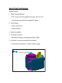
Gen III Cool Fuel System
System features:
·
Single Integrated Module
- Filter, pumps, pressure regulator and cooler, all in one unit
- Fuel flows through filter before getting to lift pump
·
More Reliable
- Fewer components
- Fewer fuel paths
·
Better Accessibility
·
“Production-Friendly”
- Eliminates installation of separate pre-filter at OEM
·
Re-usable, consumer serviceable filter element
- Pull element, dump water, re-install, continue voyage
This system will be standard on:
·
Small-Block MPI V8 Bravo
·
Small-Block MPI MIE
·
Big-Block MPI Sterndrive
·
Big-Block MPI MIE
It will not be available on:
·
V6 Sterndrive
·
Small-Block Ski
·
Small-Block Alpha
System Overview
·
Water Separating Filter Element
·
2 pumps – Lift & Pressure
- Lift pump - Gerotor
- Pressure pump – Turbine
·
Fuel Pressure Regulator
- New 288 kpa (~42 psi) regulator
- O-rings seal between OD on regulator and ID in cover, rather than a face
seal and return hose
- Regulator dumps excess fuel to inlet side of pressure pump
- Fuel pressure vs. flow characteristics differ slightly from Gen II, requires
minor calibration changes
·
Internal Low Pressure Relief Valve
- Limits pressure across lift pump to 10 psi +/- 5 psi
- Dumps fuel to inlet side of filter
System Module Features:
·
Dual Pump Configuration
- Improved Vapor Lock resistance compared to engines equipped with current
boost pumps
·
Corrosion Protection
- Strontium-coated Internal water passage (same as outboards)
- External housing e-coated
·
Engine Installation
- Low profile water connection, disconnect as required during engine
installation
- 3/8 NPTF thread inlet fuel connection
·
Service Access
- Modules located above front engine mount brackets in all applications
·
Water Jacketed
- Parallel water flow through module permits smaller module
·
Pumps immersed in fuel and draw from bottom of cavity
- Vapor rises to top of cavity, pumps always draw liquid
- Reduced pump noise – not audible over engine at idle
·
No external lines between filter, boost pump, pressure pump, and regulator
- Eliminates 20 external fuel connectors
·
5 seals, not counting inlet and outlet
- Filter cap – Modified SAE o-ring seal
- Module Cover – Controlled-Crush quad ring
- Pressure Regulator – Diametric o-ring
- Pressure Relief Valve – Diametric o-ring
- Harness – Fuel-tight pass-through fitting
·
Self-Draining
- Drains when seawater pump outlet is drained
System Overview:
Heat Exchanger
(housing - casting)
Fuel pressure
Regulator
Water Outlet
Low pressure
pump
Check Valve
(in pump)
Fuel Filter
High Pressure
Pump
To Engine
(Fuel Rail)
Water Inlet
1st stage relief
(10 psi)
Pressure
Regulator
Water Separating
Fuel Filter
Water Jacket
High Pressure
Pump
Lift Pump
( Boost Pump)
Fuel Flow Through the System
"2-Story" Water Flow Path
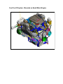
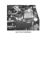
Cool Fuel III System - Mounted on Small-Block Engine
Gen III Cool Fuel Module
NOTE: This is a preliminary copy and it is subject to change.
*HQ,,,&RRO)XHO0RGXOH'LDJQRVWLFV
0RGHOV$IIHFWHG
$SSOLFDWLRQ
0RGHO
6HULDO1XPEHU
0&0
0DJ
:DQGDERYH
$OO%UDYR
/03,
:DQGDERYH
$OO%UDYR
0DJ03,
:DQGDERYH
$OO%UDYR
/03,
:DQGDERYH
0,(
/DOO
:DQGDERYH
0,(
0DJ03,
:DQGDERYH
0,(
/03,
:DQGDERYH
6LWXDWLRQ
$QHZJHQHUDWLRQRIWKH0HU&UXLVHUIXHOFRROLQJV\VWHPKDVEHHQGHYHORSHGDQGUHOHDVHG
LQWRSURGXFWLRQ7KH*HQHUDWLRQ,,,&RRO)XHOV\VWHPLQFRUSRUDWHVPDQ\GHVLJQHOHPHQWV
7KH IROORZLQJ LQIRUPDWLRQ LV SURYLGHG IRU PDLQWHQDQFH DQG WURXEOHVKRRWLQJ RI WKH
*HQHUDWLRQ,,,&RRO)XHO0RGXOH8SRQFRPSOHWLRQRIWKHVHWHVWVLISUREOHPH[LVWVUHSODFH
WKHFRPSOHWH&RRO)XHO0RGXOHDVVHPEO\
&KDQJLQJ:DWHU6HSDUDWLQJ)XHO)LOWHU(OHPHQW
:$51,1*
$YRLG)LUHRU([SORVLRQ7KHIXHOLQMHFWLRQV\VWHPLVSUHVVXUL]HGGXULQJRSHUDWLRQ8VH
FDUHZKHQUHPRYLQJWKHZDWHUVHSDUDWLQJIXHOILOWHU)XHOFRXOGVSUD\RQWKHKRWHQJLQH
FDXVLQJILUHRUH[SORVLRQ$OORZWKHHQJLQHWRFRROGRZQEHIRUHDWWHPSWLQJWRUHPRYHWKH
ZDWHUVHSDUDWLQJIXHOILOWHULQWKHIROORZLQJSURFHGXUH
:$51,1*
%H FDUHIXO ZKHQ FKDQJLQJ WKH ZDWHU VHSDUDWLQJ IXHO ILOWHU *DVROLQH LV H[WUHPHO\
IODPPDEOH DQG KLJKO\ H[SORVLYH XQGHU FHUWDLQ FRQGLWLRQV (QVXUH WKH LJQLWLRQ NH\ LV
2))'RQRWVPRNHRUDOORZVSDUNRURSHQIODPHLQWKHDUHDZKHQFKDQJLQJWKHIXHO
ILOWHU:LSHXSDQ\VSLOOHGIXHOLPPHGLDWHO\
:$51,1*
(QVXUHWKDWQRIXHOOHDNVH[LVWEHIRUHFORVLQJWKHHQJLQHKDWFK
$OORZWKHHQJLQHWRFRROGRZQ
127(0HUFXU\0HU&UXLVHUUHFRPPHQGVWKDWWKHHQJLQHEHVKXWRIIIRUKRXUVSULRUWR
ILOWHUUHPRYDO
'LVFRQQHFWWKH&RRO)XHO0RGXOHKDUQHVVIURPWKHHQJLQHZLULQJKDUQHVV
7XUQWKHNH\VZLWFKWRWKHVWDUWSRVLWLRQDQGDOORZWKHVWDUWHUWRRSHUDWHIRUVHFRQGV
WRUHOLHYHIXHOV\VWHPSUHVVXUH
7XUQNH\VZLWFKWRRIISRVLWLRQ
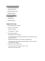
/RRVHQHDFKILOWHUDVVHPEO\UHWDLQLQJVFUHZXQWLOWKHVFUHZLVGLVHQJDJHGIURPWKH&RRO
)XHO0RGXOH'RQRWUHPRYHWKHILOWHUDVVHPEO\UHWDLQLQJVFUHZVIURPWKHILOWHUFDS
d
c
e
b
f
g
a
5658
D
E
F
G
&RRO)XHO0RGXOH
&RRO)XHO0RGXOHKDUQHVV
)LOWHUFDS and O-ring
)LOWHUDVVHPEO\UHWDLQLQJVFUHZ
H )XHOILOWHUHOHPHQW
I )LOWHUFDS
J &RRO)XHO0RGXOHILOWHUUHVHUYRLU
8QVHDWILOWHUDVVHPEO\E\JUDVSLQJILOWHUDVVHPEO\KDQGOHDQGSXOOLQJXSZDUG'RQRW
UHPRYHWKHILOWHUDVVHPEO\IURPWKH&RRO)XHO0RGXOHDWWKLVWLPH
$OORZDQ\IXHOWKDWPD\EHLQWKHILOWHUDVVHPEO\WRGUDLQRXWWKURXJKWKHERWWRPRIWKH
ILOWHUDVVHPEO\DQGLQWRWKH&RRO)XHO0RGXOHILOWHUUHVHUYRLU
5HPRYHWKHILOWHUFXSIURPWKHILOWHUFDSE\JUDVSLQJWKHILOWHUFDSDQGURWDWLQJLWLQD
FORFNZLVHGLUHFWLRQZKLOHKROGLQJWKHILOWHUFXSVWDWLRQDU\
5HPRYHWKHXVHGZDWHUVHSDUDWLQJIXHOILOWHUHOHPHQWIURPWKHILOWHUFXSSODFHLWLQD
FOHDQDSSURYHGFRQWDLQHU
'LVSRVHRIDQ\ZDWHURUGHEULVWKDWPD\EHLQWKHILOWHUFXS
,QVWDOODQHZZDWHUVHSDUDWLQJIXHOILOWHUHOHPHQWLQWRWKHILOWHUFXS3XVKWKHHOHPHQW
LQWRWKHFXSXQWLOFRPSOHWHO\VHDWHG Inspect O-ring in cap and replace if necessary.
$WWDFKWKHILOWHUFDSWRWKHILOWHUFXSE\JUDVSLQJWKHILOWHUFDSDQGURWDWLQJLWLQDFRXQWHU
FORFNZLVHGLUHFWLRQZKLOHKROGLQJWKHILOWHUFXSVWDWLRQDU\XQWLOILOWHUFDSORFNVVHFXUHO\
LQWRSODFH
,QVWDOOWKHIXHOILOWHUDVVHPEO\VORZO\LQWRWKH&RRO)XHO0RGXOHWRSUHYHQWVSLOOLQJIXHO
DQGDOLJQWKHVFUHZVUHWDLQHGLQWKHILOWHUFDSZLWKWKHVFUHZKROHVLQWKH&RRO)XHO
0RGXOH7LJKWHQWKHILOWHUDVVHPEO\UHWDLQLQJVFUHZVXQWLOKDQGWLJKW
7RUTXHHDFKILOWHUDVVHPEO\UHWDLQLQJVFUHZ
'HVFULSWLRQ
1P
OELQ
)LOWHUDVVHPEO\UHWDLQLQJVFUHZ
OEIW
5HFRQQHFWWKH&RRO)XHO0RGXOHKDUQHVVWRWKHHQJLQHZLULQJKDUQHVV
6XSSO\FRROLQJZDWHUWRWKHHQJLQH
3URSHUO\YHQWLODWHHQJLQHFRPSDUWPHQW
:$51,1*
$YRLG VHULRXV LQMXU\ RU GHDWK GXH WR ),5( RU (;3/26,21 (QVXUH WKDW HQJLQH
FRPSDUWPHQWLVZHOOYHQWLODWHGDQGWKDWQRJDVROLQHYDSRUVDUHSUHVHQWWRSUHYHQWWKH
SRVVLELOLW\RID),5(RU(;3/26,21
:$51,1*
(QVXUHWKDWQRIXHOOHDNVH[LVWEHIRUHFORVLQJWKHHQJLQHKDWFK
6WDUWWKHHQJLQH&KHFNIRUJDVROLQHOHDNVDURXQGWKHIXHOILOWHUDVVHPEO\,IOHDNVH[LVW
VWRSWKHHQJLQHLPPHGLDWHO\5HFKHFNILOWHULQVWDOODWLRQFOHDQVSLOOHGIXHODQGSURSHUO\
YHQWLODWHHQJLQHFRPSDUWPHQW&RUUHFWWKHOHDN
(OHFWULFDO
'LVFRQQHFWHOHFWULFDOFRQQHFWRUDW&RRO)XHO0RGXOH
&RQQHFW'LJLWDO9ROW2KP0HWHU'920WRHQJLQHVLGHRIHOHFWULFDOFRQQHFWRU
7XUQLJQLWLRQVZLWFKWRUXQSRVLWLRQ
9HULI\WKDWWKHUHLVYROWEDWWHU\SRZHUJRLQJWRWKH&RRO)XHO0RGXOH
127(7KHIXHOSXPSUHOD\ZLOORQO\UHPDLQDFWLYHIRUVHFRQGVZKLOHWKHNH\LVLQWKH
581SRVLWLRQ
&KHFNLQJ)XHO3UHVVXUH
&RQQHFWIXHOSUHVVXUHJDXJHWRVKUDGHUYDOYHRQIXHOUDLO
&\FOH NH\ VZLWFK WLPHV 2)) WR 581 SRVLWLRQ DW VHFRQG LQWHUYDOV WR UHDFK
PD[LPXPSUHVVXUH
9HULI\WKDWWKHSUHVVXUHLVZLWKLQVSHFLILFDWLRQ
,ISUHVVXUHLVH[FHHGVSVL
D 5HSODFH&RRO)XHO0RGXOH
,ISUHVVXUHLVHTXDOWRRUOHVVWKDQSVL
D 8VHDWHHILWWLQJDQGFRQQHFWDYDFXXPJDXJHWRWKHIXHOLQOHWVLGHRIWKH&RRO
)XHO0RGXOH'RQRWUHPRYHIXHOLQOHWILWWLQJDGDSWHU
E &\FOHNH\VZLWFKWLPHV2))WR581SRVLWLRQDWVHFRQGLQWHUYDOVWRUHDFK
PD[LPXPSUHVVXUH
F 9HULI\WKDWWKHYDFXXPIURPWKHIXHOVRXUFHLVZLWKLQVSHFLILFDWLRQ,IYDFXXPLV
H[FHHGV +J H[FHVVLYH IXHO UHVWULFWLRQ H[LVWV &RUUHFW IXHO UHVWULFWLRQ EHIRUH
SURFHHGLQJ
G :LWKYHVVHOVHFXUHGWRWKHGRFNDQGHQJLQHUXQQLQJLQQHXWUDOUHVWULFWIXHOVXSSO\
DQGYHULI\WKDWWKH&RRO)XHO0RGXOHKDVWKHDELOLW\WRFDXVHDYDFXXPUHDGLQJRI
+JRUJUHDWHU,IYDFXXPUHDGLQJLVOHVVWKDQ+JZLWKIXHOVXSSO\UHVWULFWHG
UHSODFH&RRO)XHO0RGXOH
,Q:DWHU7HVW
:LWK YDFXXP JDXJH DQG IXHO SUHVVXUH JDXJHV LQ SODFH UXQ WKH ERDW XQGHUZD\
WKURXJKRXWWKH530UDQJHDQGUHFRUGWKHSUHVVXUHDQGYDFXXPUHDGLQJV
,I IXHO VXSSO\ YDFXXP UHDGLQJ LV JUHDWHU WKDQ +J ILQG DQG FRUUHFW IXHO VXSSO\
UHVWULFWLRQ
,IIXHOVXSSO\YDFXXPLVZLWKLQVSHFLILFDWLRQDQGIXHOSUHVVXUHLVOHVVWKDQSVLUHSODFH
&RRO)XHO0RGXOH
,03257$17,WZLOOEHQHFHVVDU\WRVHDWULDOWKHERDWIROORZLQJUHSDLUVWREHVXUHWKDWWKH
SUHVVXUHDQGIXHOV\VWHPYDFXXPUHPDLQZLWKLQVSHFLILFDWLRQWKURXJKRXWWKH530UDQJH
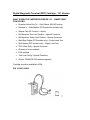
Digital Diagnostic Terminal (DDT) Cartridge - 1.31 Version
WHAT’S NEW FOR CARTRIDGE VERSION 1.31 – SMARTCRAFT
PCM’S/ECM’S
·
Guardian Active Due To: – Fault Status 2004 MY and up
·
Demand % – Data Monitor (DTS production models only)
·
‘Master Print All’ Function – History
·
Set Maximum Trim Limit Position – Special Functions
·
Set Maximum Trailer Limit Position – Special Functions
·
Start/Stop Engine (DTS models only) – Output Load Test
·
Shift Engine (DTS models only) – Output Load Test
·
TDC Offset (OB) – Special Functions
·
Glossary of terms updated
·
FAQ updated
·
Tach Link Config – Special Functions
·
All prior PCM/ECM 555 models supported
Cartridge should be available in 2004.
P/N 91-880118A04
Computer Diagnostic System
Mercury Marine has partnered with SPX Corporation to develop a PC-based
diagnostic system called “Computer Diagnostic System” or “CDS”. This system is
designed to aid the dealership technician by reducing the diagnostic times
required to identify the root cause of electrical and electronic fuel controlled
system problems. The software consists of a user friendly menu driven interface,
engine data screens, step-by-step pinpoint guided diagnostics for certain models,
internet connectivity for timely software updates, and integrated service manuals.
The following pages contain information about this system.
CDS Section Table of Contents
Computer Diagnostic System Announcement Letter
CDS / DDT Comparison Matrix
CDS FAQ's
Computer Diagnostic System Components
Computer Requirements for running the Mercury Computer
Diagnostic System (CDS) software and hardware
Computer Diagnostic System – Service Bulletin 2004-04
Dear Mercury Trade Partner
In recent years, Mercury Marine has made significant enhancements to our outboard and
MerCruiser engines. These changes were made to improve reliability, performance and
increase customer satisfaction with our products. These same changes also made our
engines more complex and sometimes more difficult to diagnose problems. Mercury
Marine has expended considerable effort in developing a system that will simplify
troubleshooting problems with these more complex engines.
Mercury Marine has partnered with SPX Corporation to develop a PC-based diagnostic
system called “Computer Diagnostic System” or “CDS”. This system is designed to aid
the dealership technician by reducing the diagnostic times required to identify the root
cause of electrical and electronic fuel controlled system problems. The software consists
of a user friendly menu driven interface, engine data screens, step-by-step pinpoint
guided diagnostics for certain models, internet connectivity for timely software updates,
and integrated service manuals.
The basic Computer Diagnostic System is offered in three different configurations. The
first will consist of diagnostic software, SmartComms Interface Box, storage case, Dell
D500 laptop and Quick Setup Guide. The second configuration includes all of the items
listed above and includes a “Rugged” Panasonic CF-18 laptop computer in place of the
Dell D500 laptop. The third configuration available is designed for our partners who have
recently purchased a computer and do not wish to purchase another. We offer the
diagnostic software and SmartComms Interface Box to those who have a computer that
meets the minimum system requirements.
Optional kit accessories available include: an Electrical Harness Break-Out Box, Harness
Pin Probes, 12 Volt DC Adapters, and the DMT 2004 VOM Meter with communications
interface. Additionally Mercury Precision Parts is developing an Electronic Dual Pressure
Tester with communications interface. These communications interfaces will reduce
required technician key strokes, remove entry errors and decrease troubleshooting times
when using the pinpoint guided diagnostics.
Please read the accompanying materials for additional details.
Sincerely,
Mercury Marine
CDS
View and Clear – Current and Historic Codes
4 lines displayed
10 lines displayed
Read Data Stream Items
MerCruiser
555 PCM / ECM
GM MEFI
Thunderbolt V
Outboard
555 PCM / ECM
2000 and prior DFI ECM
2.5L with 824003 ECU
3.0L Fuel ECM
3.0L Ignition ECM
2.5L Hi-Performance ECM
(1998 and later)
FourStroke Carbureted ECM
225 / 115 EFI FourStroke
Future Product
(CAN and DTS Control Module)
Display Data Stream
4 items
14 items
DDT
•
Short periods of time
Large periods of time
Multiple Files
•
•
*
•
•
•
•
*
*
*
*
•
•
•
•
•
Updatable Diagnostic Information
Requires new cartridge
Software updates are downloaded
via internet or DVD
Print Diagnostic Data
Special printer, difficult to use and interpret
Standard printer, easy to use and understand
*
•
*
*
•
Manual advance single frame at a time
Automatic advance
Trouble code indicator during playback
•
•
•
•
•
•
Electronic File Transfer
to Mercury Technical Service
Static – both engine data and fault buffers
•
Dynamic recorded files – allows review
of running engine over periods of time
•
Supports Multiple Languages
*
*
Electronic Service Manuals
•
MerCruiser
Mercury / Mariner Outboards
•
M2 Jet Drives
•
•
•
•
•
•
Pinpoint Guided Diagnostics
•
•
Circuit specific colored wiring diagrams
•
•
Color photographs show
component locations
•
Stores electronic file of diagnostic sequence
•
Step-by-step diagnostic trees
•
•
Digital Volt Ohm Interface
•
•
Water Test Record Module
•
•
Automatic recording started by fault code
Manual recording with lanyard switch
* Future enhancements to CDS
#
1 On The Water
Promotion # MM03-572
•
•
•
•
Playback Recorded Files
Ability to use different display methods
•
Active Tests
DDT
Record Data
•
Racing
Data Display Options
Single item expanded mode
with min. / max.
4 item meters with min. / max.
4 item graphs
CDS
1-800-345-2233
•
•
The Computer Diagnostic System (CDS) is Mercury Marine’s next generation diagnostic tool.
The tool replaces the Quicksilver (DDT) Scan Tool currently used in Mercury Marine dealerships.
Here is a list of frequently asked questions regarding CDS.
1. Why is the Quicksilver (DDT) Scan Tool being replaced?
Two main reasons, first; the DDT is being phased out of
production by the supplier. There are limited amounts of the
DDT available at this time. Second: The processor inside the
DDT is older technology and limited in its communications
speed. With the migration to the Control Area Network (CAN)
on the newer products, the DDT can only read filtered
communications from the ECM, not real-time
communications on the CAN bus.
2. Will I still be able to use my DDT Scan Tool?
Yes. You will still be able to use your DDT Scan Tool on
older products and current production engines. Use on
future products will be limited. Currently we are planning
one additional cartridge release for the DDT.
3. Does the CDS contain legacy information?
Yes. At the start of production the CDS system will read all
555 ECM & PCM processors, along with the MerCruiser
MEFI engines from 1994. As development continues, we
expect to include the older digital outboard engines.
4. What are the major components of the CDS system?
The CDS system consists of a laptop computer using the
Windows 2000 operating system and a SmartComms
interface box. The interface box allows the computer
to communicate with the ECM on the engine. Other
components are available and explained in the
advertising literature.
5. Will I need new cables to connect the CDS system to
the engine?
The current DDT cables connect directly onto the
SmartComms interface box and work with the CDS system.
Of course, newer products may require the purchase of
additional cables. Every attempt is being made to use the
existing cables.
6. Where can I purchase a CDS system?
Contact SPX at the address given in the advertising
literature. You will need your dealer information. Under
contract SPX cannot sell the CDS system to anyone unless
approved by Mercury Marine.
7. What is the warranty on the CDS system?
The standard warranty is for three years? If you wish,
extended warranty coverage can be purchased at an
additional cost. Refer to the advertising literature for
additional information.
8. Can I load other software onto the CDS laptop?
Yes, the system is not locked down. Please note that this is
done at your own risk. We support the standard
configuration and setup. The recovery disk supplied with the
CDS system will return the unit back to the original setup,
any additional data will be lost.
9. What additional functionality does the CDS offer over
the DDT?
Refer to the comparison matrix for detail between the
two systems.
10. Who do I call for technical assistance?
Contact SPX at 1-800-345-2233 between 8:00-5:00 E.S.T.
11. What is the difference between the Basic and Deluxe kits?
The Basic kits allow the technician to perform fundamental
diagnostic tests. The Deluxe kits contain hardware that will
maximize the CDS software. The technician will be able to
perform Water tests, PinPoint diagnostics, multimeter
functions and probe wiring harnesses.
12. How will the CDS software be updated?
Based on the file size, the CDS software will be updated with
a new DVD or FTP session.
13. Can I purchase the CDS software and load it on my own PC?
Yes, CDS can be loaded onto any PC but the software has
only been validated and approved to work on either the
Panasonic Toughbook CF18 or Dell D500 laptops. Loading
CDS software on other hardware may create driver
configurations and other conflicts preventing CDS and
possibly other applications from working properly. Please
contact 1-800-345-2233 for additional information.
#
1 On The Water
Promotion # MM03-572
1-800-345-2233
CDS - Computer Diagnostic System Components
Dell Latitude Laptop Computer
Panasonic Toughbook Laptop Computer
SmartComms Module
Pin Probe Kit & Loaded Volts Lead
Break-Out Box
New Digital Meter With Serial Connection for Conecting
to Laptop
Various Kit Configurations Available
Computer Requirements for running the Mercury Computer
Diagnostic System (CDS) software and hardware:
·
·
·
·
·
·
·
·
·
900 MHz Pentium Processor
USB port
Windows 2000 (or XP backed down to 2000)
56K Modem
PCMCIA slot
256 MB Ram
DVD Drive
10 GB Hard Drive
Serial Port
6HUYLFH%XOOHWLQ
:DUUDQW\,QIRUPDWLRQ
3DUWV,QIRUPDWLRQ
&LUFXODWHWR
6DOHV0DQDJHU
6HUYLFH,QIRUPDWLRQ
$FFRXQWLQJ
%XOOHWLQ1R
2(01R
6HUYLFH0DQDJHU
7HFKQLFLDQ
3DUWV0DQDJHU
&RPSXWHU'LDJQRVWLF6\VWHP
0RGHOV$IIHFWHG
0HU&UXLVHU
0RGHOV&RYHUHG
6HULDO1XPEHU2U<HDU
0&00,(0(),(),7%,DQG03,*DVROLQH0RGHOV
$OO0RGHOV
0&00,(3&0(&0RU3&0*DVROLQH0RGHOV
$OO0RGHOV
0HUFXU\0DULQHU2XWERDUGV
0RGHOV&RYHUHG
6HULDO1XPEHU2U<HDU
2SWL0D[ZLWK3&0RU3&0
DQGXS
(),ZLWK3&0RU3&0
(),)RXU6WURNHZLWK(&0
DQGXS
-HW'ULYHV
0RGHOV&RYHUHG
6HULDO1XPEHU2U<HDU
'),
$OO0RGHOV
(),ZLWK3&0
$OO0RGHOV
0HUFXU\5DFLQJ
0RGHOV&RYHUHG
6HULDO1XPEHU2U<HDU
2XWERDUGVZLWK3&0RU3&0
$OO0RGHOV
0HU&UXLVHU0RGHOVZLWK0(),)XHO,QMHFWLRQ
$OO0RGHOV
0HU&UXLVHU0RGHOVZLWK3&0RU3&0
$OO0RGHOV
)XWXUHVRIWZDUHUHOHDVHVZLOOLQFOXGHRWKHUPRGHOVZLWKGLJLWDOSURFHVVRUV
7+(,1)250$7,21,17+,6'2&80(17,6&21),'(17,$/$1'3527(&7('%<&23<5,*+7$1',67+(3523(57<2)0(5&85<0$5,1(
7KLVGRFXPHQWLVSURYLGHGIRUWKHVROHDQGH[FOXVLYHXVHRIWKHRULJLQDOUHFLSLHQWDVSUHVFULEHGE\0HUFXU\0DULQHDQGPD\QRWEHGLVWULEXWHGRUFRSLHGGLJLWDOO\RURWKHUZLVH
ZLWKRXWWKHSULRUZULWWHQFRQVHQWRI0HUFXU\0DULQH
50$<
k0HUFXU\0DULQH
3DJH
&RPSXWHU'LDJQRVWLF6\VWHP
6LWXDWLRQ
0HUFXU\ 0DULQH KDV SDUWQHUHG ZLWK 63; &RUSRUDWLRQ WR GHYHORS D 3&EDVHG V\VWHP
GHVLJQHG WR DLG WKH GHDOHUVKLS WHFKQLFLDQ E\ UHGXFLQJ WKH GLDJQRVWLF WLPHV UHTXLUHG WR
LGHQWLI\WKHURRWFDXVHRIHOHFWULFDODQGHOHFWURQLFIXHOFRQWUROOHGV\VWHPSUREOHPV7KH
VRIWZDUH FRQVLVWV RI D XVHU IULHQGO\ PHQX GULYHQ LQWHUIDFH HQJLQH GDWD VFUHHQV
VWHSE\VWHSSLQSRLQWJXLGHGGLDJQRVWLFVIRUFHUWDLQPRGHOVLQWHUQHWFRQQHFWLYLW\IRUWLPHO\
VRIWZDUHXSGDWHVDQGLQWHJUDWHGVHUYLFHPDQXDOV
7KHEDVLF&RPSXWHU'LDJQRVWLF6\VWHP&'6LVRIIHUHGLQWKUHHGLIIHUHQWFRQILJXUDWLRQV
7KHILUVWZLOOFRQVLVWRIGLDJQRVWLFVRIWZDUH6PDUW&RPPV,QWHUIDFH%R[VWRUDJHFDVH'HOO
'ODSWRSDQG4XLFN6HWXS*XLGH7KHVHFRQGFRQILJXUDWLRQLQFOXGHVDOORIWKHLWHPV
OLVWHGDERYHDQGLQFOXGHVD5XJJHG3DQDVRQLF&)ODSWRSFRPSXWHULQSODFHRIWKH
'HOO'ODSWRS7KHWKLUGFRQILJXUDWLRQLVGHVLJQHGIRURXUSDUWQHUVZKRKDYHUHFHQWO\
SXUFKDVHGDFRPSXWHUDQGGRQRWZLVKWRSXUFKDVHDQRWKHU7KHGLDJQRVWLFVRIWZDUHDQG
6PDUW&RPPV ,QWHUIDFH %R[ LV RIIHUHG WR WKRVH ZKR KDYH D FRPSXWHU WKDW PHHWV WKH
PLQLPXPV\VWHPUHTXLUHPHQWV
2SWLRQDONLWDFFHVVRULHVDYDLODEOHLQFOXGHDQ(OHFWULFDO+DUQHVV%UHDN2XW%R[+DUQHVV
3LQ3UREHV9ROW'&$GDSWHUVDQGWKH'079200HWHUZLWKFRPPXQLFDWLRQV
LQWHUIDFH$GGLWLRQDOO\0HUFXU\3UHFLVLRQ3DUWVLVGHYHORSLQJDQ(OHFWURQLF'XDO3UHVVXUH
7HVWHU ZLWK FRPPXQLFDWLRQV LQWHUIDFH 7KHVH FRPPXQLFDWLRQV LQWHUIDFHV ZLOO UHGXFH
UHTXLUHGWHFKQLFLDQNH\VWURNHVUHPRYHHQWU\HUURUVDQGGHFUHDVHWURXEOHVKRRWLQJWLPHV
ZKHQXVLQJWKHSLQSRLQWJXLGHGGLDJQRVWLFV
9HUVLRQLQ(QJOLVKLVDYDLODEOHRWKHUODQJXDJHVZLOOEHVXSSRUWHGLQIXWXUHUHOHDVHV
7KH&'6V\VWHPZLOOXVHWKHVDPHGLDJQRVWLFKDUQHVVDVVHPEOLHVDVWKH''7'LDJQRVWLF
KDUQHVVDVVHPEOLHVDUHQRWLQFOXGHGLQWKHNLWIURP63;DQGPXVWEHRUGHUHGIURP0HUFXU\
3UHFLVLRQ3DUWV7KHGLDJQRVWLFKDUQHVVDVVHPEOLHVDUHOLVWHGDWWKHHQGRIWKHEXOOHWLQ
0LQLPXP6\VWHP5HTXLUHPHQWV
0+]3HQWLXP3URFHVVRU
86%SRUW
:LQGRZV
.0RGHP
3&0,$VORW
0%5DP
'9''ULYH
*%+DUG'ULYH
Serial Port
2UGHULQJ,QIRUPDWLRQ
7RJHWDGGLWLRQDOLQIRUPDWLRQSULFLQJRUWRRUGHUWKH&RPSXWHU'LDJQRVWLFV\VWHPFRQWDFW
63;&RUSRUDWLRQ
28635 Mound Rd.
:DUUHQ0,
RUFDOO
86$
&DQDGD
(XURSH
$XVWUDOLD
$GDSWHU&DEOH+DUQHVVHV
0HUFXU\0DULQHU2XWERDUGDQG-HW'ULYH$GDSWHU+DUQHVVHV
+DUQHVVHVDUHSXUFKDVHGIURP0HUFXU\3UHFLVLRQ3DUWV
7+(,1)250$7,21,17+,6'2&80(17,6&21),'(17,$/$1'3527(&7('%<&23<5,*+7$1',67+(3523(57<2)0(5&85<0$5,1(
7KLVGRFXPHQWLVSURYLGHGIRUWKHVROHDQGH[FOXVLYHXVHRIWKHRULJLQDOUHFLSLHQWDVSUHVFULEHGE\0HUFXU\0DULQHDQGPD\QRWEHGLVWULEXWHGRUFRSLHGGLJLWDOO\RURWKHUZLVH
ZLWKRXWWKHSULRUZULWWHQFRQVHQWRI0HUFXU\0DULQH
3DJH
k0HUFXU\0DULQH
0$<
5
&RPSXWHU'LDJQRVWLF6\VWHP
127($OOKDUQHVVHVDUHQRWXVHGZLWKFXUUHQWVRIWZDUHUHYLVLRQOHYHO)XWXUHVRIWZDUH
UHOHDVHVZLOOXVHDGGLWLRQDOKDUQHVVHV
'HVFULSWLRQ
3DUW1XPEHU
/&DUE(QJLQHV
$
DQGXS/(),ZLWK(&0RQO\
3UR0D[6XSHU0D[6XSHU0DJQXP
DQGXS'),2SWL0D[2XWERDUGV
$
/(),DQG&DUE2XWERDUGV8VHZLWK$
$
/(),DQG&DUE2XWERDUGV8VHZLWK$
$
$OO+L3HUIRUPDQFH//(),2XWERDUGVZLWK$(&0RQO\
$
8VHZLWK$
KSF\FOH2XWERDUGV8VHZLWK$
$
([WHQVLRQ+DUQHVVSLQPIW8VHZLWK$
7
'LJLWDO2SWL0D[2XWERDUGVRQO\7KLV7+DUQHVVDOORZVWKH''7
7
WREHFRQQHFWHGXQGHUWKHGDVKDWWKHSLQWDFKRPHWHUKDUQHVVRXWOHW
)RU9HUDGRKSDGDSWVIODWSLQFRQQHFWRUWRSLQ
$KDUQHVV
7
9HUDGRKS&\FOH2XWERDUGVSLQFRQQHFWRUVQRDGGLWLRQDO
$
KDUQHVVUHTXLUHG
(),)RXU6WURNH1RWIRUXVHZLWKWKH''7
&$1GLDJQRVWLFVFDEOH&RQQHFWVLQWRDMXQFWLRQER[RUPDOHWRPDOH
DGDSWHUFDEOHIRU&RPPDQG0RGXOHFRQILJXUDWLRQ1RWIRUXVHZLWKWKH
''7
$
0DOHWRPDOHDGDSWHUFDEOH$OORZVFRQQHFWLRQEHWZHHQ&$1
FRPPXQLFDWLRQVFDEOHDQG&RPPDQG0RGXOHKDUQHVVLQDSSOLFDWLRQV $
ZKHUHDMXQFWLRQER[LVQRWXVHG
0HUFXU\0DULQHU2XWERDUG,QMHFWRU7HVW+DUQHVVHV
'HVFULSWLRQ
3DUW1XPEHU
DQGXS///(),2XWERDUGV8VHZLWK$
DQGXS+L3HUIRUPDQFH////(),2XWERDUGV8VH $
ZLWK$
DQGXS+L3HUIRUPDQFH////(),2XWERDUGV
LQFOXGLQJ2IIVKRUHPRGHOV8VHZLWK$
$
0HU&UXLVHU$GDSWHU+DUQHVVHV
+DUQHVVHVDUHSXUFKDVHGIURP0HUFXU\3UHFLVLRQ3DUWV
7+(,1)250$7,21,17+,6'2&80(17,6&21),'(17,$/$1'3527(&7('%<&23<5,*+7$1',67+(3523(57<2)0(5&85<0$5,1(
7KLVGRFXPHQWLVSURYLGHGIRUWKHVROHDQGH[FOXVLYHXVHRIWKHRULJLQDOUHFLSLHQWDVSUHVFULEHGE\0HUFXU\0DULQHDQGPD\QRWEHGLVWULEXWHGRUFRSLHGGLJLWDOO\RURWKHUZLVH
ZLWKRXWWKHSULRUZULWWHQFRQVHQWRI0HUFXU\0DULQH
50$<
k0HUFXU\0DULQH
3DJH
&RPSXWHU'LDJQRVWLF6\VWHP
127($OOKDUQHVVHVDUHQRWXVHGZLWKFXUUHQWVRIWZDUHUHYLVLRQOHYHO)XWXUHVRIWZDUH
UHOHDVHVZLOOXVHDGGLWLRQDOKDUQHVVHV
'HVFULSWLRQ
3DUW1XPEHU
)RU0(),(&0PRGHOV
$
)RU3&0PRGHOVDGDSWVSLQ0HU&UXLVHUFRQQHFWRUWRSLQ
2XWERDUGKDUQHVV
7
DQG
$
)RU3&0PRGHOVSLQFRQQHFWRUVQRDGGLWLRQDOKDUQHVV
UHTXLUHG
$
DQGXS9DQG9&DUE(QJLQHVZLWK7KXQGHUEROW9,JQLWLRQ
$OORZV530KLVWRU\VWRUHGLQ,JQLWLRQ0RGXOHWREHUHDG8VHZLWK
$
$
&$1GLDJQRVWLFVFDEOH&RQQHFWVLQWRDMXQFWLRQER[RUPDOHWRPDOH
DGDSWHUFDEOHIRU&RPPDQG0RGXOHFRQILJXUDWLRQ1RWIRUXVHZLWKWKH
''7
0DOHWRPDOHDGDSWHUFDEOH$OORZVFRQQHFWLRQEHWZHHQ&$1
FRPPXQLFDWLRQVFDEOHDQG&RPPDQG0RGXOHKDUQHVVLQDSSOLFDWLRQV $
ZKHUHDMXQFWLRQER[LVQRWXVHG
7+(,1)250$7,21,17+,6'2&80(17,6&21),'(17,$/$1'3527(&7('%<&23<5,*+7$1',67+(3523(57<2)0(5&85<0$5,1(
7KLVGRFXPHQWLVSURYLGHGIRUWKHVROHDQGH[FOXVLYHXVHRIWKHRULJLQDOUHFLSLHQWDVSUHVFULEHGE\0HUFXU\0DULQHDQGPD\QRWEHGLVWULEXWHGRUFRSLHGGLJLWDOO\RURWKHUZLVH
ZLWKRXWWKHSULRUZULWWHQFRQVHQWRI0HUFXU\0DULQH
3DJH
k0HUFXU\0DULQH
0$<
5
2
2004
Product Update
Section 2
Electrical Systems
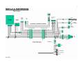
Table of Contents
2005 SmartCraft DTS Updates
Service/Repair of Electrical Test Equipment
2005
496/8.1 DTS changes and over
view of the new 5.0 DTS
DTS 496 / 8.1 New Harness Plug Locations
2005
5.0L MPI – BRAVO DTS
Engine Block: GM 5.0L
Engine Controller: PCM 03
Fuel Injection: Sequential Fuel Injection
TBU: 80mm Electric
Flame Arrestor Flow: 500 CFM @ 1 in Hg Manifold and 28” Hood Pressure
Maximum Flame Arrestor Height From Crankshaft: 557 mm
Rated Crankshaft HP: 260 Horsepower
Rated WOT Speed: 4600-5000 RPM
Transom Type: Bravo, Analog & Digital Sender, Magnum, Exhaust Tube
Available Options
Bravo 1: 1.65 (P), 1.50 (O)
Bravo 2: 2.20 (P), 2.43 (H), 2.00 (O)
Bravo 3: 2.20 (P), 2.43 (H), 2.00 (O)
FWC: Full System, Exhaust Manifolds Included, Air Actuated Water Drain STD
RWC: With Air-Actuated Water Drain
RWC: With 3-Point Drain
3” Risers
6” Risers
Jackshaft Ready
CHS: Compact Hydraulic Steering
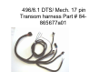
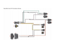
496/8.1 DTS/ Mech. 17 pin
Transom harness Part # 84865677a01
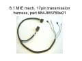
8.1 MIE DTS 17 pin transmission
harness, ZF Hurth part # 84865676a01
8.1 MIE mech. 17pin transmission
harness, part #84-865769a01
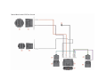
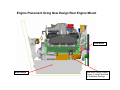
Over view of the 5.0 DTS engine
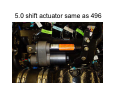
5.0 shift actuator same as 496
From left to right; 4 pin diagnostics, 6 pin paddle wheel /fuel tanks,17 pin
transom harness and 2 pin clean power
top of bracket 14 pin Deutsch
Termination Resistors Can 1 Yellow Can 2 new Blue
HVS Cam sensor location used on Small Block DTS
80 MM Electronic Throttle Body same as 496/8.1 DTS
PCM 03 controller uses box part number 885558 same as used on
496/8.1 DTS engines
5 Relays used from left to right Trim down /Trim up /Fuel pump
Main Power/Start relay. Small block DTS are used with Bravo
Transom assy, with 3 wire SmartCraft Trim sender
b
6HUYLFH%XOOHWLQ
:DUUDQW\,QIRUPDWLRQ
6HUYLFH,QIRUPDWLRQ
%XOOHWLQ1Rb
3DUWV,QIRUPDWLRQ
&LUFXODWHWR
6DOHV0DQDJHU
$FFRXQWLQJ
6HUYLFH0DQDJHU
7HFKQLFLDQ
3DUWV0DQDJHU
6HUYLFH5HSDLURI(OHFWULFDO7HVW(TXLSPHQW
1RWLFH
7KLVEXOOHWLQUHSODFHV0HU&UXLVHU6HUYLFH%XOOHWLQ
7HVW(TXLSPHQW
$OOHOHFWULFDOWHVWHTXLSPHQWPXVWEHUHWXUQHGWRWKHYHQGRURUUHSDLUIDFLOLW\IRUVHUYLFH
UHSDLUDQGRUUHSODFHPHQWSDUWV$Q\HOHFWULFDOWHVWHTXLSPHQWUHFHLYHGLQ)RQGGX/DF
VKDOOEHUHWXUQHGWRWKHVHQGHU:HHQFRXUDJHFRQWDFWZLWKWKHEXVLQHVVSULRUWRVKLSSLQJ
WKH XQLW WR REWDLQ VKLSSLQJ HVWLPDWH DQG UHSDLU GHWDLOV 7KH DGGUHVVHV DQG SKRQH
QXPEHUVDUHIROORZLQJ
9HQGRU
(OHFWURQLF6SHFLDOWLHV,QF
3LHUFH'ULYH
6SULQJ*URYH,/
)D[b
(TXLSPHQW
3DUW1XPEHU
7LPLQJ/LJKWVHOIFRQWDLQHG
0XOWL0HWHU'9$
0HUFWDFK'LJLWDO7DFKRPHWHU
$
(),7HVWHU
$
127( 'LJLWDO 9ROW 0HWHU LV QRW VHUYLFHDEOH 3XUFKDVH D JRRG TXDOLW\ PHJ RKPV
LPSHGDQFH1RWXVLQJPHJRKPVLPSHGDQFHPD\QRWDOORZ(),WHVWHUWRQRUPDOL]H
9HQGRU
(TXLSPHQW
0HUF27URQLF6HUYLFH'HSDUWPHQW
%UDQFK
32%R[
$OPRQW0,
)D[b
3DUW1XPEHU
7DFK'ZHOO0HWHU
,JQLWLRQ$QDO\]HU
7+(,1)250$7,21,17+,6'2&80(17,6&21),'(17,$/$1'3527(&7('%<&23<5,*+7$1',67+(3523(57<2)0(5&85<0$5,1(
7KLVGRFXPHQWLVSURYLGHGIRUWKHVROHDQGH[FOXVLYHXVHRIWKHRULJLQDOUHFLSLHQWDVSUHVFULEHGE\0HUFXU\0DULQHDQGPD\QRWEHGLVWULEXWHGRUFRSLHGGLJLWDOO\RU
RWKHUZLVHZLWKRXWWKHSULRUZULWWHQFRQVHQWRI0HUFXU\0DULQH
5b'(&(0%(5b
k0HUFXU\0DULQH
3DJHb
b
6(59,&(5(3$,52)(/(&75,&$/7(67(48,30(17
9HQGRU
(TXLSPHQW
1RWDYDLODEOH
5HSODFHPHQWSDUWVDUHQRWDYDLODEOH
3DUW1XPEHU
7KXQGHUEROW,JQLWLRQ$QDO\]HU
$
92$0HWHU
0DUN7HVWHU
9HQGRU
63;&RUSRUDWLRQ
3DUN'ULYH
2ZDWRQQD01
,QWHUQDWLRQDO
$
(TXLSPHQW
3DUW1XPEHU
'LJLWDO'LDJQRVWLF7HVWHU''7
$
127($Q\HOHFWULFDOWHVWHTXLSPHQWUHFHLYHGLQ)RQGGX/DFVKDOOEHUHWXUQHGWRWKH
VHQGHU
9HQGRU
(TXLSPHQW
3DUW1XPEHU
%OXH3RLQW3URGXFWV
'07'LJLWDO7DFKRPHWHU0XOWLPHWHU 6:$OOHQ%OYG6WH '07$'LJLWDO7DFKRPHWHU
%HDYHUWRQ25
0XOWLPHWHU
127( 3OHDVH FDOO DQG PDNH UHSDLU DUUDQJHPHQWV SULRU WR VHQGLQJ PHWHU %OXH3RLQW
7HFKQLFDODQG&XVWRPHU6HUYLFHRIILFHKRXUV$0303DFLILF7LPH=RQH
7+(,1)250$7,21,17+,6'2&80(17,6&21),'(17,$/$1'3527(&7('%<&23<5,*+7$1',67+(3523(57<2)0(5&85<0$5,1(
7KLVGRFXPHQWLVSURYLGHGIRUWKHVROHDQGH[FOXVLYHXVHRIWKHRULJLQDOUHFLSLHQWDVSUHVFULEHGE\0HUFXU\0DULQHDQGPD\QRWEHGLVWULEXWHGRUFRSLHGGLJLWDOO\RU
RWKHUZLVHZLWKRXWWKHSULRUZULWWHQFRQVHQWRI0HUFXU\0DULQH
3DJHb
k0HUFXU\0DULQH
'(&(0%(5bb
5
3
2005
Product Update
Section 3
Exhaust and Cooling Systems
Table Of Contents
MerCruiser Dry Joint Exhaust and Cooling System - V6, V8 Small
Block
MCM Exhaust Elbow Height Change
MerCruiser
Dry Joint
Exhaust and Cooling System
V6, V8 Small Block
Strategy Behind MerCruiser
Exhaust System Changes
• Prevent Coolant Leaks.
• Eliminate Water from Leaking into Exhaust
Passages.
• Help Prevent Reversion.
• Insure More Robust Exhaust Collection &
Muffling System.
Start of Dry Joint System
• MCM V6 Models: S/N 0M615000-UP.
• MCM V8 Models: S/N 0M600000-UP.
• MIE V8 Models: S/N 0M0317000-UP.
Dry Joint Design Changes
•
•
•
•
New Exhaust Manifold.
New Exhaust Elbow.
New Gaskets.
New Risers.
Dry Joint Gaskets
• Built-in Turbulator
– Traps Condensation From Elbow
– Traps Water Reversion
– Increases Local Flow Velocity
• Water & Exhaust Separated
– Better Sealing
– No Leakage into Exhaust
Dry Joint Gaskets
• New Materials
– 18 gauge 316 ss Core.
– Two Layer 5000o F GrafoilTM, Seals Exhaust Passage.
– High Temp 4 Bead Silicone Seals Water Ports.
– Perfect Seal Protects Manifold and Elbow.
Dry Joint Gaskets
• Coat Edge of All Water Ports with Perfect Seal.
• If Bare Metal on Gasket Surface, use Perfect
Seal.
Restrictor Gasket
Restrictor End of Gasket is Straight
Open
Restricted
Open End of Gasket is Contoured
Restrictor Gasket
• Used on All Raw Water Cooled Engines
on the Manifold.
• Restrictor Opening Goes Toward End That
Bypass Water Comes From Thermostat
Housing Into Exhaust Elbow.
• Turbulator Points Upward.
Full Flow Gasket
Open
Open
Both Ends of Gasket are Contoured
Full Flow Gasket
• Used on All Engines with Risers.
• Goes Between the Riser and Exhaust Elbow.
• Turbulator Points Upward.
Block Off Gasket
Closed
Closed
Both Ends of Gasket are Straight
Block Off Gasket
• Used on All Closed Cooled Engines.
• Goes Between the Exhaust Manifold and Riser.
• Turbulator Points Upward.
Installation Reminder
• Current MIE Inboard and Tow Sports V-Drive
Requirements.
–
–
–
–
–
–
–
Test & Verify Exhaust System Designs
6.9-13.7 kPa (1-2 psi) Exhaust Back Pressure.
Maintain Adequate Support of System Components.
Use Exhaust Resonators if They Help.
Use at Least Minimum Size Exhaust Hoses.
Use Heat Resistant Exhaust Hose.
Use at Least 2 Clamps per Connection.
Dry Joint 14o Exhaust Elbow
Dry Joint Service Manual
• Nbr 37 V8 Service Manual Supplement.
– 90-864260020 Oct 2002.
• Section 6 Cooling System.
– All Models.
– Seawater System.
– Closed Cooling System.
• Section 7 Exhaust System.
– Manifolds and Elbows.
– Cold Riser Models.
– Warm Riser Models.
• Section 10 Color Diagrams.
– Water Flow Diagrams.
MCM Exhaust Elbow Height Change
• Project Objectives
– Provide V-6 and S.B. V-8 MCM engines with
increased elbow height
– Increase exhaust elbow outlet angle
– Create 1.7 inch riser for applications that
would necessitate an engine box redesign
– Provide 6 inch riser kit for V-6
– SOP date by November 2004
Exhaust Elbow Height
• System Overview
– Current MIE elbow will become standard on
all V-6 & S.B. V-8 MCM’s except inline ski
• Increases height by 1.5 inches over current MCM
– Factory option for 1.7, 3 & 6 inch risers for
MCM and 3 & 6 MIE
– New intermediate exhaust pipes required
• Individual pipes for each elbow/riser height
Exhaust Elbow Height 1.5”
Elbow Only
Exhaust Elbow Height 3.2”
Elbow, 1.7” Riser
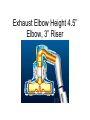
Exhaust Elbow Height 4.5”
Elbow, 3” Riser
Exhaust Elbow Height 7.5”
Elbow, 6” Riser
Exhaust Elbow Height Summary
V6 MCM
Models
SB V8
MCM
Models
SB V8 Inboard Models
(either rear or fwd
facing exh)
SB V8 Towsports
Models w / Rear
Facing Exhaust
SB V8 Towsports
Models w /
Fwd Facing
Exhaust
1.81
standard
standard
standard
N/A
standard
3.20
3.51
factory
option
factory
option
kit
N/A
kit
864591 (tall) Elbow + 3.00" Riser
4.50
4.81
factory
option
factory
option
factory option
N/A
N/A
864591 (tall) Elbow + 6.00" Riser
7.50
7.81
kit
kit
factory option
N/A
N/A
864309 (short) Exhaust Elbow Only
0.00
0.00
N/A
N/A
N/A
standard
N/A
864309 (short) Elbow + 1.70" Riser
1.70
1.70
N/A
N/A
N/A
kit
N/A
864309 (short) Elbow + 3.00" Riser
3.00
3.00
N/A
N/A
N/A
N/A
N/A
864309 (short) Elbow + 6.00" Riser
6.00
6.00
N/A
N/A
N/A
N/A
N/A
Exhaust Elbow or Elbow / Riser
Combination
External
¨ Height
(in)
Overall
¨ Height
(in)
864591 (tall) Exhaust Elbow Only
1.50
864591 (tall) Elbow + 1.70" Riser
Exhaust Elbow Height
Turbulator will be removed from full flow gasket “New” PN 865786A01
Exhaust Elbow Height
Intermediate Pipes
New V6
New intermediate pipes will be labeled with model, riser size and pn.
Improved alignment with bullhorn
Exhaust Elbow Height
Intermediate Pipes
Exhaust Elbow Height
• System Overview
– Flow control valve installed on thermostat
housing for RWC 350 MAG & MX 6.2 MCM &
MIE
• Balances water flow between banks
Exhaust Elbow Height
• New Service Kit’s
– 1.7 inch riser’s
• 865995A01 RWC Warm Riser
• 865996A01 FWC Warm Riser
• 866007A01 RWC Tow Sports Warm Riser
– Supplementary hose’s
• 865022A01 V6 MPI RWC 6” riser
• 865998A01 V6 MPI FWC 6” riser
Exhaust Elbow Height
• New Service Kit’s
– Intermediate Elbow Kit’s (2 elbows per kit)
•
•
•
•
•
•
866000A01 V6 1.7” riser
866001A01 V6 3” riser
866002A01 V6 6” riser
866003A01 SB V8 1.7” riser
866004A01 SB V8 3” riser
866005A01 SB V8 6” riser
Exhaust Elbow Height
• Service Kit’s
– Several existing kits will be impacted
• CC for MPI & Carb
• 3 & 6 inch riser
• Long block
2005
Product Update
Section 4
Transom Assemblies
4
Table of Contents
Quick Connects
• Gear Lube Bottle Relocation
• Oil Reservoir Hose
• Power Trim Hoses
• Power Steering Hoses
• Bravo Transom Water Hose
• Speedometer Hose
• MerCathode Assembly
Power Trim Pump Fuse Change
New Trim Pump Harness
Control Harness to Trim Pump Adaptor Harness
Trim Pump Reservoir Cap Change
Oil Bottle Float Change
New Rear Engine Mount Design (Quick Mounts)
Shift Plate Assembly Redesign
Intermediate Shift Cable Redesign
Transom Plate Assembly Components
Quick Connects
Added For Reduced Installation Time
and Secure Connections
Gear Lube Bottle Relocation
Previous
Design
Released
Design
•
Project Definition
– Relocate gear lube bottle to eliminate
interferences
– Add inline quick connection to lube line
•
Benefits
– Eliminate improper connection
between hose and gimbal housing due
to space limitations
– Reduce installation time
– SN 0M640000 and up
•
Start of Production
– March 10, 2003 - completed
Inline Quick Connect
New Oil Reservoir
Quick Connects
There is a new quick connect fitting between the oil
reservoir bottle and the current 90 degree quick connect
fitting at the transom for easier removal and installation
of the bottle for cleaning and or engine removal
• 3/10/03 started with serial numbers 0M640000.
Quick Connect
at Gimbal
Hsng
Drive Lube
Monitor
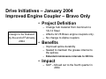
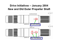
Drive Initiatives – January 2004
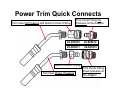
Power Trim Quick Connects
Old Design
• Project
– Hydraulic quick connect fittings
– Brass Construction – brass components
shown in picture
– In March 2004 the Male fittings on both the
trim pump adapter and the trim line from the
transom will change from brass to stainless
steel
– Affects Alpha and Bravo Drives
• Benefits
– Male / Female connections to insure correct
connections
• Impact
New Design
– SOP – January 12, 2004
– Hydraulic lines will be connected - no plugs
to remove
– Single hand installation
Power Trim Quick Connects
Trim Hose Up Pressure and Quick Connect Fitting
Trim Pump Fitting Up
Pressure at the Adapter
22-865410
22-865412
22-865411
22-865413
Quick Connect Fitting
Trim Hose Down Pressure
Trim Pump Fitting
Down pressure at
the Adapter
§ Power steering hose quick-connect fittings
– Reduce installation time and opportunity for leaks
• All Sterndrive models with power steering
New Design
Current Production
Drive Initiatives – January 2004
Power Steering Quick Connects
•
Project Definition
– Quick connect fittings
– Nickel Plated Brass Construction
– Affects Alpha and Bravo Drives
•
Benefits
– Eliminate cross threading on power
steering cylinder
– Reduce installation time
– Male / Female connections to insure
correct connections
•
Installation Clearance - .85”
OEM Impact
– Overall fitting height is 0.5” taller, requires
.85 installation clearance
– Hydraulic lines will be connected - no
plastic coupler
– Single hand installation
– SOP – January 5, 2004
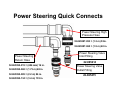
Power Steering Quick Connects
Power Steering High
Pressure Hose
32-865387-053 = (1.3 m) 53in.
32-865387-060 = (1.5 m) 60 in.
Power Steering
Return Hose
32-865390-015 = (406 mm) 16 in.
32-865390-068 = (1.73 m) 68 in.
32-865390-085 = (2.2 m) 86 in.
32-865390-134 = (3.4 m) 135 in.
Power Steering Valve
Inlet Fitting
22-865414
Power Steering Valve
Outlet Fitting
22-865415
Drive Initiatives – January 2004
Transom Water Hose Fitting
• Project
OLD DESIGN
865470
– Redesign the inlet water fitting
located on the transom.
– Add quick connect fitting to inlet
water hose
– Minimize flow restriction through
fitting.
– Affects Bravo Drives Only
• Benefits
– Reduce installation time at
– Improved water flow through
fitting
22-865324
NEW DESIGN
• Impact
– SOP – January 8th, 2004
Drive Initiatives – January 2004
Sea Pump Water Hose Quick Connect
22-865324
• Project
– Provide easier installation for
inlet hose via a quick
connect junction in between
transom and sea pump
– Affects Bravo Drives Only
• Benefits
22-865362
– Eliminates difficulty
associated with removal of
hose from inlet of sea pump
• Impact
– SOP – January 9th, 2004
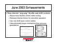
Speedometer Quick Connect June 2003
Old Design
• Project Definition
– Quick connect fitting
– Nickel Plated Brass / Plastic Construction
– Affects Alpha and Bravo Drives
New Quick Connect
• Benefits
– Male connector factory installed on gimbal
housing – sealed when disconnected
– SmartCraft steering / speedo kit will
incorporate same fittings
• OEM Impact
– Female connector included in parts bag
– SOP – June 16, 2003
– Single hand / blind installation
MerCathode Assembly
•
Project Definition
– Add sealed connector in MerCathode
harness to reduce installation time
– Improve aesthetics on product
Previous
Design
– SN 0M640000 and up (Bravo
Applications)
– Launched in conjunction with gear lube
relocation and quick connect changes
•
Start of Production
– March 10, 2003 completed
Released
Design
New MerCathode Quick Connect Feature
MerCathode Quick Connects
The service replacement MerCathode unit will come with the connector
disassembled for ease in replacement through the hydraulic manifold
New Quick Connect Design
Old Design
Drive Initiatives – January 2004
Fuse change – Trim Pump
• Project
– Replace glass fuse assembly
with flat blade style fuse
• Benefits
– Eliminate damage to fuse during
disassembly of fuse holder
– Automotive style fuse
• Impact
– SOP – January 12, 2004
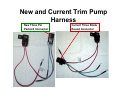
New Trim Pump Harness
Fuse and Holder
New Three Pin
Connector
New and Current Trim Pump
Harness
New Three Pin
Packard Connector
Current Three Blade
Round Connector
Control Harness to Trim Pump
Adapter Harnesses
A02
A02
Control Harness to Trim Pump
Adapter Harness
Trim Pump Reservoir Cap
Change
Problem: Trim Pump Cap Leaks
• Trim pump purges oil through side
vents in rough water applications.
Root Cause:
• Cap vents are large enough to allow
sloshing oil to pass from reservoir to
the exterior.
Solution:
• Provide a baffle in cap which allows
air to vent but reduce the ability for
liquid to migrate. New cap has a
(yellow colored baffle and a rubber seal
gasket) installed.
Current Status:
•Tested in Placida and passed with
no leakage
•New design went in to production
starting with serial number 0M680000
Oil Bottle Float Change
The float in the oil reservoir bottle
was improved to prevent it from
sealing off the outlet when the
bottle is filled from the top, causing
the audio warning to sound even
though the bottle was filled
The new float went into production
on 5/19/03 Starting S/N 0M653864
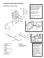
New Rear Engine Mount Design
Note: New engines use a
modified rear engine mount
system (a). The bottom of
the rear mount now has a
knurled edge (b) [older
version was smooth].
Alpha Shown - Bravo Similar
The "double-wound"
lockwasher (spring) is no
longer used.
The large fiber washer is
still used.
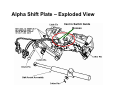
1 - Transom Plate Assembly
2 - Pivot Bolts
3 - Tab Washers
4 - Screw Engine Mounting
5 - Washer
6 - Spacer
7 - Washer - Fiber
8 - Lockwasher - Double Wound
9 - Locknut
10- Washer
11- Locknut
12- Shift Cable Outer Casing
13- End Guide
14- Core Wire Anchor
15- Anchor Screws
16- Core Wire
17- Shift Slide
18- Screw - Core Wire Cavity
19- Gimbal Housing Eyelet
20- Cable Wrapping
NOTE: Some OEM's
have not yet made the
final modifications to
the boat stringers
(front engine mounts
are now lower). A
.104 in. stainless steel
washer is placed in
the center of each
fiber washer to slightly
raise the engine when
installed.
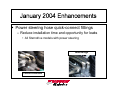
Drive Changes – June 2003
Improved Engine Alignment
•
Project Definition
–
Address offset at nominal (detected
by stack-up) at the rear engine
mount / inner transom plate
interface – additional material to be
added to rear engine mounts
–
Minimize future potential for
misalignment due to component
stack-up in the following areas:
•
•
•
–
–
•
Rear engine mounts / inner transom plate
interface
Engine coupler position / flywheel interface
Engine coupler perpendicularity / flywheel
interface
Tied in with coupler improvements
Affects Alpha and Bravo Drives
Benefits
–
Eliminate misalignment (MerCruiser
product) at the Dealer & OEM.
Eliminates double-wound lock washer
– SOP – June 17, 2003
New Rear Engine
Mount Design
Old and New Style Mounts
Old Engine Mount
New Engine Mount
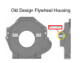
Old Design Flywheel Housing
Mount Location
Old Style Rear Mount Installed
Flywheel Housing
Rear Mount (old)
Spring Washer
Inner Transom Plate
New Design Flywheel Housing
Mount Location
New Style Rear Mount Installed
Flywheel Housing
Rear Mount ( New)
Inner Transom Plate
Engine Placement When Using Old Style Rear Engine Mount
Front Mount
Boat Stringer
Misalignment Clearance
Caused when old mount was
used. Some Boatbuilders
Compensated For This By
Raising stringer Heights
Engine Placement Using New Design Rear Engine Mount
Front Mount
Boat Stringer
New Mount Design Lowers
Engine To Height Specified
In Installation Drawings
b
:DUUDQW\,QIRUPDWLRQ
6HUYLFH,QIRUPDWLRQ
3DUWV,QIRUPDWLRQ
&LUFXODWHWR
%XOOHWLQ1Rb
6DOHV0DQDJHU
$FFRXQWLQJ
2(01Rb
6HUYLFH0DQDJHU
7HFKQLFLDQ
3DUWV0DQDJHU
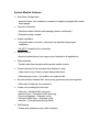
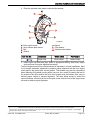
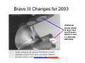
0&05HDU(QJLQH0RXQW'HVLJQ&KDQJH
0RGHOV$IIHFWHG
0&0/0&0/0&003,0&0/0&003,0&0/0&0
0$* 03, 0&0 0$* 03, +25,=21 0&0 0; 03, 0&0 03, 0$*
+25,=210&00$*0$*+2
6LWXDWLRQ
6WDUWLQJ ZLWK VHULDO QXPEHU 0 DQG DERYH WKH UHDU HQJLQH PRXQWV KDYH EHHQ
UHGHVLJQHGWRLPSURYHHQJLQHDOLJQPHQWEHWZHHQWKHWUDQVRPDQGWKHHQJLQH:LWKWKLV
GHVLJQ WKH GRXEOH ZRXQG ORFN ZDVKHU KDV EHHQ UHPRYHG DQG WKH IO\ZKHHO KRXVLQJ
HQJLQHPRXQWKDVEHHQDGMXVWHGWREHWWHUDOLJQWKHHQJLQHFRXSOHUWRWKHJLPEDOEHDULQJ
c
c
d
d
e
e
a
a
g
f
f
b
D
E
F
G
2ULJLQDOGHVLJQ
5HDUHQJLQHPRXQW
,QQHUWUDQVRPSODWH
%ROW
:DVKHU
b
1HZGHVLJQ
H 6SDFHU
I )LEHUZDVKHU
J 'RXEOHZRXQGZDVKHU
7+(,1)250$7,21,17+,6'2&80(17,6&21),'(17,$/$1'3527(&7('%<&23<5,*+7$1',67+(3523(57<2)0(5&85<0$5,1(
7KLVGRFXPHQWLVSURYLGHGIRUWKHVROHDQGH[FOXVLYHXVHRIWKHRULJLQDOUHFLSLHQWDVSUHVFULEHGE\0HUFXU\0DULQHDQGPD\QRWEHGLVWULEXWHGRUFRSLHGGLJLWDOO\RU
RWKHUZLVHZLWKRXWWKHSULRUZULWWHQFRQVHQWRI0HUFXU\0DULQH
5b2&72%(5b
k0HUFXU\0DULQH
3DJHb
b
0&05($5(1*,1(02817'(6,*1&+$1*(
7KHQHZIO\ZKHHOKRXVLQJPRXQWLVVHUUDWHGRQWKHERWWRPVLGHZKHUHLWPDNHVFRQWDFW
ZLWKWKHVXSSRUWPRXQWHDURQWKHLQQHUWUDQVRPSODWHDVVHPEO\7KHNQXUOZLOOSUHYHQW
PRXQWZLQGXSZKHQWLJKWHQLQJWKHUHDUPRXQWEROWWRWKHQXWLQWKHLQQHUWUDQVRPSODWH
a
mc79724-1
1HZGHVLJQ
2OGGHVLJQ
D .QXUO
:KHQ0&0HQJLQHVVWDUWHGVKLSSLQJRQWKHUHDUHQJLQHPRXQWZDVFKDQJHGWR
WKHQHZGHVLJQ:KHQWKLVQHZGHVLJQVWDUWHGWKHLQQHUWUDQVRPSODWHDVVHPEO\KDGWKH
GRXEOHZRXQGORFNZDVKHUVDQGWKHILEHUZDVKHUVUHPRYHGDVSDUWRIWKHQHZGHVLJQ
7KHILEHUZDVKHUVZHUHODWHUSXWEDFNRQWRWKHLQQHUSODWHWRHOLPLQDWHDQ\SRVVLEOHW\SH
RI HQJLQH IO\ZKHHO KRXVLQJ FRQWDFW ZLWK WKH LQQHU WUDQVRP SODWH PRXQWLQJ HDU :KHQ
UHSRZHULQJDERDWWKHQHZUHSODFHPHQWHQJLQHPD\UHTXLUHWKHDGGLWLRQRID6SDFHU.LW
31$WREHLQVWDOOHGEHWZHHQWKHUHDUHQJLQHPRXQWDQGWKHLQQHUWUDQVRP
SODWHPRXQWLQJHDU(DFKNLWFRQWDLQVWKHSDUWVUHTXLUHGWRVKLPRQHHQJLQH3URFHGXUH
VKRZQIROORZLQJ
,QVWDOODWLRQ
127((QVXUHWKDWWKHLQQHUWUDQVRPSODWHPRXQWLVFOHDQDQGIUHHRIDOODGKHVLYHDQG
GHEULV
$SSO\JOXHWRWKHILEHUZDVKHUDQGSRVLWLRQLWHTXDOO\DURXQGWKHUHDUHQJLQHPRXQW
EROWKROHRQWKHLQQHUWUDQVRPSODWHPRXQW
7+(,1)250$7,21,17+,6'2&80(17,6&21),'(17,$/$1'3527(&7('%<&23<5,*+7$1',67+(3523(57<2)0(5&85<0$5,1(
7KLVGRFXPHQWLVSURYLGHGIRUWKHVROHDQGH[FOXVLYHXVHRIWKHRULJLQDOUHFLSLHQWDVSUHVFULEHGE\0HUFXU\0DULQHDQGPD\QRWEHGLVWULEXWHGRUFRSLHGGLJLWDOO\RU
RWKHUZLVHZLWKRXWWKHSULRUZULWWHQFRQVHQWRI0HUFXU\0DULQH
3DJHb
k0HUFXU\0DULQH
2&72%(5bb
5
b
0&05($5(1*,1(02817'(6,*1&+$1*(
3ODFHWKHVWDLQOHVVVWHHOZDVKHULQVLGHWKHILEHUZDVKHU
c
d
e
a
g
b
f
mc79566-1
D
E
F
G
5HDUHQJLQHPRXQW
,QQHUWUDQVRPSODWHPRXQW
%ROW
:DVKHU
7XEH5HI1R
162
H 6SDFHU
I )LEHUZDVKHU
J 6WDLQOHVVVWHHOZDVKHU
'HVFULSWLRQ
:KHUH8VHG
3DUW1XPEHU
6XSHU*OXH
)LEHUZDVKHU
2EWDLQ/RFDOO\
LQVWDOO HQJLQH LQWR ERDW DQG DOLJQ 5HIHU WR DSSURSULDWH 0HUFXU\ 0HU&UXLVHU HQJLQH
VHUYLFHPDQXDOIRUHQJLQHDOLJQPHQWSURFHGXUH
7KHIURQWHQJLQHPRXQWVKDYHDOLPLWHGDPRXQWRIDGMXVWPHQW,QVRPHLQVWDOODWLRQVWKHUH
LV QRW HQRXJK GRZQZDUG DGMXVWPHQW WR DFKLHYH SURSHU DOLJQPHQW ZLWK WKH IURQW HQJLQH
PRXQWSDGVLQWKHERDWDWWKHLUFXUUHQWSRVLWLRQ7KLVVLWXDWLRQPD\DOVREHHQFRXQWHUHG
ZKHQUHSODFLQJROGIO\ZKHHOKRXVLQJZLWKDQHZRQH$VDUHVXOWRIORZHULQJWKHUHDURI
WKH HQJLQH WR WKH LGHDO SRVLWLRQ WKH IURQW RI WKH HQJLQH PXVW EH ORZHUHG HYHQ PRUH WR
DFKLHYH SURSHU HQJLQH WR WUDQVRP DOLJQPHQW 7KH FKDUW EHORZ VKRZV E\ PRGHO WKH
QRPLQDOGLVWDQFHPHDVXUHGDWWKHIURQWHQJLQHPRXQWWKDWWKHIURQWRIWKHHQJLQHPXVW
EHORZHUWRDFKLHYHSURSHUDOLJQPHQW
7+(,1)250$7,21,17+,6'2&80(17,6&21),'(17,$/$1'3527(&7('%<&23<5,*+7$1',67+(3523(57<2)0(5&85<0$5,1(
7KLVGRFXPHQWLVSURYLGHGIRUWKHVROHDQGH[FOXVLYHXVHRIWKHRULJLQDOUHFLSLHQWDVSUHVFULEHGE\0HUFXU\0DULQHDQGPD\QRWEHGLVWULEXWHGRUFRSLHGGLJLWDOO\RU
RWKHUZLVHZLWKRXWWKHSULRUZULWWHQFRQVHQWRI0HUFXU\0DULQH
5b2&72%(5b
k0HUFXU\0DULQH
3DJHb
b
0&05($5(1*,1(02817'(6,*1&+$1*(
1RPLQDO'URS$W)URQW0RXQW8VLQJ1HZ5HDU(QJLQH0RXQWV
0RGHO
PPLQ 7UDQVRP7KLFNQHVV 7UDQVRP7KLFNQHVV
6SDFHU
PPLQ PPLQ
/$OSKDZLWKIURQW
SHGHVWDOPRXQW
:LWK
:LWKRXW
/$OSKDZLWKVLGH
PRXQWV
:LWK
:LWKRXW
/$OSKD%UDYR
:LWK
:LWKRXW
/$OSKD%UDYR
:LWK
:LWKRXW
/$OSKD%UDYR
:LWK
:LWKRXW
0DJ$OSKD%UDYR
:LWK
:LWKRXW
0;03,%UDYR
:LWK
:LWKRXW
0DJ03,
%UDYR%DVH+2
:LWK
:LWKRXW
PPLQ
PPLQ
PPLQ PPLQ
PPLQ
PPLQ
PPLQ PPLQ
PPLQ
PPLQ
PPLQ PPLQ
PPLQ
PPLQ
PPLQ PPLQ
PPLQ
PPLQ
PPLQ PPLQ
PPLQ
PPLQ
PPLQ PPLQ
PPLQ
PPLQ
PPLQ PPLQ
PPLQ
PPLQ
PPLQ PPLQ
7+(,1)250$7,21,17+,6'2&80(17,6&21),'(17,$/$1'3527(&7('%<&23<5,*+7$1',67+(3523(57<2)0(5&85<0$5,1(
7KLVGRFXPHQWLVSURYLGHGIRUWKHVROHDQGH[FOXVLYHXVHRIWKHRULJLQDOUHFLSLHQWDVSUHVFULEHGE\0HUFXU\0DULQHDQGPD\QRWEHGLVWULEXWHGRUFRSLHGGLJLWDOO\RU
RWKHUZLVHZLWKRXWWKHSULRUZULWWHQFRQVHQWRI0HUFXU\0DULQH
3DJHb
k0HUFXU\0DULQH
2&72%(5bb
5
Shift Plate Assembly June 2003
•
Project Definition
– Redesign shift plate assembly to
eliminate improper installation of shift
interrupt and gear indicator switches
– Affects Alpha and Bravo
New Design
•
Benefits
– Eliminate failure / claims due to
improperly assembled shift plate
assemblies (switch plunger engagement)
– Repeatable and consistent shift events
– Decrease adjustments to shift cables
•
Impact
– Threaded stud/nuts replaced with stud
and cotter pin
– SOP June 17, 2003
– Original release included hair pin Cotters,
– changed to cotter pins on 8/23/03
Old Design
Alpha Shift Plate – Exploded View
Cast in Switch Guide
Bosses
New Shift Levers for Alpha & Bravo
Shift Plate Assemblies
Neutral Switch adjustment notch
Drive Initiatives – June 2003
Intermediate Shift Cable
• Project Definition
Black Teflon Coating
– Alpha and Bravo intermediate
shift cable redesign / resource to
reduce friction and lost motion
– Affects Alpha and Bravo
• Benefits
– Reduce required bend radius
• Impact
New Crimp method to prevent
water leak
– Installs exactly as the old style
cable did
– Went into production on June
17th 2003
Alpha / Bravo Shift Cables
BRAVO
Intermediate Shift Cable
Part # 865437 A02
ALPHA
Intermediate Shift Cable
Part # 865436 A02
§ New internal “wig-wag” throttle and shift controls
–
–
–
–
Allows more flexible control cable routing
Reduced internal friction for smoother operation
Use new SAE-style control cables
Uses physically larger mechanism than previous
generations
2005
Product Update
Section 5
Sterndrives
5
Table of Contents
New Alpha One Gen II Drive Shaft Housing Oil Seal Installation Tool
Bravo Drive Updates and Changes
x Bravo Engine Coupler Redesign
x Bravo Universal Joint Assembly Changes
x U-Joint Retainer Nut
x Bravo Drive Shaft Housing Driven Gear Information
x Bravo Gear Upgrade Components
x Bravo Drive Shaft Housing Chimney Bearing Placement
x Bravo Chimney Bearing Removal Tool
x Bravo Lower Drive Shaft Comparison
x Standard and High Performance Prop Shafts
x Bravo Three Propeller Shaft and Oil Seals
Bravo III Changes for 2003
x Additional Anodes
x Bravo III Bearing Carrier/Forward Propeller Issues
x Bravo Three Thrust Bearing Redesign
New for Bravo 2003/2004
x Bravo Shift Lever Detent Redesign
x Bravo Cone Clutch Redesign
x Bravo Drive Shaft Housing Restyling
x Shift Shaft Cavity Seal Redesign
New Bravo 2004 Shimming Process
New Alpha One Generation II
Drive Shaft Housing Oil Seal Installation Tool
91-864497 New Integrated Oil Seal
Installation Tool
New Integrated Oil Seal
Part Number 26-864319
91-817570T ( Two Seal
Installation Tool)
Old Style (Back to Back)
Oil Seal Installation Part
Number 26-66302
New Alpha One Generation II Drive Shaft
Housing Oil Seal Installation Tool
91-864497
Drive Initiatives – January 2004
Improved Engine Coupler – Bravo Only
• Project Definition
Design to be finalized
by the end of February
2004
– Change hub material from Aluminum to
12L14 Steel
– Affects All V8 Bravo engine couplers only.
– No change to Alpha couplers
• Benefits
– Improved spline durability
– Sealed to maintain the grease internal to
the splines
– Extended maintenance intervals to 300 hrs
• Impact
– SOP – Moved out to the fourth quarter in
2004
Bravo Engine Couplers
Current Bravo Small Block
Current Bravo Big Block
Proposed New Design Bravo
Engine Coupler
Proposed Bravo Gas Engine
Coupler Design
•Shortened snout to provide
installation clearance
•Shielded for grease retention
•Grease channel to direct
lubrication to splines
•Steel insert
Bravo Universal Joint Assy.
•
•
•
•
•
•
•
The Bravo U-Joint Assembly has changed from the Rockwell U-joint
assembly to the GKN assembly.
The Rockwell assembly is Gray in color, where as the GKN assembly
is Black in color.
The Rockwell assembly has the Cross & Bearing end caps retained
with clips at the bottom of the cap inside of the yoke ear.
The GKN assembly has the Cross & Bearing end caps retained with
the clips above the cap on the outside of the yoke ear for Standard
Bravo and Alpha.
The Rockwell U-Joint assembly was a greaseable assembly.
The GKN is a Permalube style like the Alpha U-Joint assembly and
cannot be greased.
The GKN Bravo X assembly is Black in color and has the Cross &
Bearing end caps retained with clips at the bottom of the cap inside of
the yoke ear as did the [ Bachman U-Joint Assembly ] Rockwell style.
Comparison of Rockwell to
the GKN U-Joint Assy.
GKN U-Joint Repair Parts
Alpha / Bravo Std.
• ALPHA
Universal Joint Assembly
Stub Yoke Gear End
Center Socket
Splined Yoke Engine Coupler End
Cross and Bearing Assembly
864281A 2
864282T
865503T
864281A01
865493A01
• BRAVO Std.
Universal Joint Assembly
Stub Yoke Gear End
Center Socket
Splined Yoke Engine Coupler End
Cross and Bearing Assembly
864244A 2
864245T
865503T
864244A01
865496A01
Rockwell U-Joint Assembly
Bravo Standard
GKN U-Joint Assembly
Bravo “X”
GKN U-Joint Assembly
Repair parts for the GKN “X” Drive U-Joint Assembly such as the
part numbers for all of the individual replacement parts are being
worked on and will be brought out at a later date in 2004
Bravo (X)
U-Joint Assemblies
New L18 GKN U-Joint Assembly ( Bravo X Drives)
• Original style Driven gear (1999 & Prior)
• New style Replacement Gear for 1999 & prior as
well as current Bravo Drives.
• Old Style Cone Clutch
• with the number “7”
New Upgrade cone clutch
with the Top Groove
• Original Chimney bearing positioning for 1999 & prior Bravo
Drives
• Proper positioning of the Top Cover and Drive Shaft
Housing Chimney Bearing.
• 91-90773T
• Original
91-864220
Upgrade
91-862530
2000 & up
Individual Replacement Puller Tool part Numbers for Bravo
Service Tool 91-90244A 1
Bravo Service Tool 91-90244A 1 replacement part numbers. When you order
part number 91-90777T1 puller Jaw, used to remove the sleeve bearing from the
Top Cover Bearing Chimney or the Driveshaft Housing Bearing Chimney, you
only receive one half of the tool. Part number 91-90778 puller jaw will also have
to be ordered to make the puller tool complete.
91-90778
91-90777T1
• We have had some reports of Bravo Three propeller shaft oil seal
leakage.
• Samples of the production oil seal were placed on test in our
engineering test cells to check for leakage.
• The oil seals were also measured by our quality department to make
sure that they were made to print.
• After measuring oil seal samples that were taken from production,
the seals were found to be out of print.
• The seal vendor was then contacted to set up a meeting on the
quality and design issue of the oil seal.
• The first thing that was done was to increase the ID of the Urethane
retainer at the outside seal towards the propeller.
• The next thing that was done was to have the vendor make the oil
seals to print and air freight them to our facility for testing.
• The new oil seals that were made to print were much better.
• Our next step is to get a total new redesign for the oil seal and that
is in process at this time.
• New improved propshaft seals – Bravo Three
– New lip design, material and spring tension
– Greatly reduces potential for leakage and early
failure
Bravo III Changes for 2003
Additional
Anode added
to Gear Case
and Propeller
Shaft on June
17, 2003 S/N
0M179452
Bravo III Anode Design Targets
¾Add 43% Anode Volume w/ Dual Gearcase and
Propeller shaft Anode
¾Baseline -current 17.41 in³ (285.3 cm³)
¾Actual - added 4.52 in³ (74.07 cm³) – 25.9 % increase w/
propeller shaft anode
¾Actual – added 2.79 in³ (45.72 cm³) - 16 % increase w/ dual
gearcase anode
¾Actual – total added 7.31 in³ (119.79 cm³)- 41.9% w/
propeller shaft and dual gearcase anode
¾Increase Hull Potential to Improve Protection
¾Freshwater target 750 – 1050 mv
¾Saltwater target 850 – 1150 mv
Bravo III Bearing Carrier
Threads machined
after anodizing
• You may have also heard that the front propeller was hitting on the
bearing carrier causing some surface rub damage.
• It was found to be several issues.
• 1) The ID of the front propeller is now opened up by an additional
one hundred thousands per side to eliminate any possible rub.
• 2) The propellers were not within the balance specifications of the
print and were adding to the oil seal leaks as well as the hitting
on the carrier.
• 3) There was some Devcon that is used as a filler for small amounts
of porosity in the casting that was hitting on the bearing carrier,
Devcon is a filler material commonly used in most all of the
Stainless steel cast process propellers as a filler for porosity.
• 4) There was some casting flash that had not been properly cleaned
out of the bottom radius of the bore causing some of the rubbing.
Bravo Three Bearing Carrier
Damage / Propeller Defect
Bravo Three Bearing Carrier
Damage / Propeller Defect
•
•
Heavy deposit on lower rib of propeller causing it to rub on the
bearing carrier.
Heavy Devcon Deposit on lower section of rib on inner propeller,
causing it to rub on the bearing carrier.
Bravo Three Bearing Carrier
Damage / Propeller Defect
•
Casting Flash on leading edge of propeller rib, Devcon across the
face of the rib causing the propeller to Gaul on the bearing carrier.
Bravo Three Bearing Carrier
Damage / Propeller Defect
•
•
•
The new version of the front propeller.
Version One is the Machined current version using the letter (X) as an
identifier.
Version Two is the new Cast version using the letter (A) as an
identifier.
Drive Initiatives – January 2004
New Thrust Bearing
• Project Definition
– Redesigned bearing to
improve durability.
– Increased roller diameters
– Bravo III only
Current Design
• Benefits
– Longer Bearing Life
– Dynamic Load Rating
• Impact
– SOP – January, 2004
New Design
Drive Initiatives – January 2004
New and Old Outer Propeller Shaft
New Shaft Marking
Older Shaft Markings
Drive Initiatives – May 2004
• Project Definition
– initiatives directed at improving the
following:
• NVH / Shift Effort
– Bravo shift lever detent
– Revised engine management during shift
event ECM / PCM
– Bravo Clutch Geometry
• Bravo Styling
– Ribbed Top Cover – Bravo (X) Only
– Drive Shaft Housing, Top Cover & Rear
Cover
– Decals
– Start of Production
May 31, 2004
– End Model Number Change
Drive Initiatives – May 2004
Bravo Shift Lever Detent
• Project Definition
Baseline & Prototype Shift Handle Loads
• Benefits
20
18
16
14
Load (lb.)
– Modify Detent Shape
– Smooth detent transition from
forward into neutral and from
reverse into neutral.
– Improve positioning of detent
canister
– Affects Bravo Drives only
– Not applicable to Bravo X
Drives
12
Baseline TR# 2002-771
10
Rapid Proto TR# 2002-7739
8
– Reduces shift loads measured
at control handle by 17%
– NVH Improvement
Impact
6
4
2
0
N-F
F-N
N-R
Shift Operation
R-N
Av.
– Standard Bravo Drives only
SOP – May 31, 2004
Bravo Shift Lever Detent Socket
Current Bravo Shift Lever
New Design Bravo Shift Lever
Bravo Shift Lever Detent Socket
Used in all Bravo X and XR
Stern Drives with High Bump
Brass Sleeves
Used in all Standard Bravo
Stern Drives with Low Bump
Brass Sleeves
Drive Initiatives – May 2004
Bravo Cone Clutch Redesign
Drive Initiatives – May 2004
Bravo Cone Clutch Redesign
Current Bravo Cone Clutch
New Design Bravo Cone Clutch
Drive Initiatives – May 2004
Bravo Styling
•
Project Definition
– Restyling of
• Upper Driveshaft Housing
(DSH)
• Rear Cover
• Top Cover
• Decals
– No external changes to Bravo Drive
since 1987
– Affects Bravo Drives only
•
Current
Design
Bravo
New Design
Bravo
June 2004
Benefits
– Enhanced aesthetics to identify the
new and improved Bravo Drive
•
Impact
– External Steering Suppliers may
require changes to their components
to match DSH changes
– SOP – May 31, 2004
Bravo Drive Shaft Housing
The “O” ring for the drive shaft housing shift
shaft bore has been replaced with a new seal.
Shift Cavity Seal
19-865866
Bravo Drive Shaft Housing
The “O” ring for the drive shaft housing shift shaft bore has been
replaced with a new seal. Part Number 19-865866
New Designed Seal
Introducing the New Bravo
Jan, 2004 Shimming process
•
•
•
•
•
•
•
The Bravo drives for 2004 will have the gears in the drive shaft
housing shimmed into position to improve on gear life.
The Universal joint pinion gear will be shimmed for gear depth.
The driven gears will be set by checking gear lash.
There are new shims for the U-joint pinion gear bearing set as well
as a new bearing pack to allow shimming to be done.
The new shims will be placed between the new special bearing cup
and the aluminum shoulder in the U-joint snout.
The new shims will come in 0.001 graduated sizes, starting at
(0.71mm) 0.028 through (1.02mm) 0.040 in size.
The driven gear shims will also come in .001 graduated sizes,
starting at (1.47mm) 0.058 through (1.70mm) 0.067.
U-joint and Driven Gear Bearing
Spacer Cup for all Bravo Drives
• New U-joint shouldered bearing pack spacer cup and
bearing.
U-joint and Driven Gear Shims
and Chart
•
New U-joint shouldered bearing pack Chart and Shim.
Bravo 2004 Driven Gear Thrust
Bearing Race and Chart
Gear Lash Specification Chart
for Bravo 2004
•
•
•
•
•
Gear Tooth Count
27 x 32
27 x 29
23 x 30
16 x 19
Spiral Tooth Gear
Spiral Tooth Gear
Spiral Tooth Gear
Straight Tooth Gear
Gear Lash
.011 - .016
.013 - .018
.011 - .016
.010 - .015
New Shimming Tools Required
to shim a Bravo Upper
• U-Joint pinion gear shimming tool
U-Joint pinion gear shaft tools
• Standard Bravo
• All Bravo X models
Gear Lash Flags for the new
shimming procedure
Holding Block and Rod assembly
for the Dial Indicator
•
Dial Indicator holder rod and retaining nut.
•Dial Indicator holding block.
Handle Fixture for checking
Gear Lash
•
Handle fixture for checking gear lash.
Driven Gear Clamp Tool
•
Clamp tool to hold driven gear when checking gear lash.
To order the Complete Tool Kit Including both sets of Shims required
to Fully Shim the NEW Bravo Upper Drive Shaft Housing
Order Tool Kit Part Number 91-865114 A01
New Shimming procedure for
Bravo Upper 2004
•
•
Step 1) Place the new U-Joint bearing pack on to the gear as you
have in the past, by pressing the first bearing roller and cone
assembly onto the gear until it bottoms on the gear. Next place
the bearing cup for that bearing over the cone and roller
assembly.
Step 2) Place the center cup/spacer over the gear and press the
second bearing onto the gear until a slight preload is felt. Stop
at that point, now place the assembly you just set up over the
U-joint along with the large thrust washer and the retainer
nut assembly and adjust the bearing preload to (.9 Nm) 8 lb. in.
for new bearings and (.6 Nm) 5 lb. In. for used bearings.
New Shimming procedure
(continued)
•
Step 3) After the bearing preload is set remove the gear and bearing
pack from the U-joint assembly along with the large thrust
support washer, place them over the stub shaft tool. 91865084 for the standard Bravo and 91-865083 for the (X)
models and reinstall the pinion nut and washer, (DO NOT)
over tighten the pinion nut, just tighten the nut and washer
until it feels firmly seated against the gear.
New Shimming procedure
(continued)
•
•
Step 4) In this step you will insert the original shim thickness that
came out of the drive or a starting shim of (.089mm) .035 and
the U-joint bearing pack and pinion gear on the shaft tool into
the housing bore.
Step 5) Install the U-joint retainer nut and torque to (271Nm) 200 lb. ft.
(use the reference chart for the actual torque that must be
applied per the length of the torque wrench being used).
New Shimming procedure
(continued)
•
Step 6) Insert Pinion gear shimming tool 91-865114 into the top of the
driveshaft housing using the proper gear tooth count for the
gear ratio of the unit being worked on.
New Shimming procedure
(continued)
•
•
•
•
Step 7)
Using a feeler gauge between the tool face and the gear
teeth measure for the (0.64mm) .025 distance between
the gear teeth and the face of the shimming tool. If a
change is required the shims come in (.0254mm) .001
increments. Make the changes and recheck for the
(0.64mm) .025 distance between the gear teeth and the
face of the tool.
Step 8) Next loosen the U-joint assembly retainer nut and
remove the gear and bearing assembly, using caution to
prevent damaging the shims in the snout.
Step 9) You now will place a (1.62mm) .064 shim race thickness
as a starting point into the drive unit under the driven gear
or the original shim race that was removed when the unit
was disassembled.
Step 10) Now install the driven gear set and the thrust bearing
into the housing.
New Shimming procedure
(continued)
•
•
Step 11) Place the thrust bearing on the top gear along
with the shim race (thickness that was originally
removed) or a (1.62mm) .064 starting point shim race,
install the top cover and torque to (27Nm) 20 lb. ft.
Step 12) Making sure that the gears are lined up (+) plus over (-)
minus and the gears are in the proper position with the
marks on the back of the driveshaft housing.
New Shimming procedure
(continued)
•
•
Step 13) Reinstall the U-joint gear and bearing pack with the
stub shaft tool that you previously removed and
retorque the retainer nut to (271 Nm) 200 lb. ft.
Step 14) Next you will place the proper gear lash flag per the
gear ratio of the drive, onto the stub of the shaft that
you just installed with the U-joint pinion gear and
bearing pack.
New Shimming procedure
(continued)
•
Step 15) The next step will be to install the clamp block and handle
assembly onto the end of the U-joint stub tool on the Pinion
gear and bearing pack tightening it lightly at this point, just
enough to keep the tool from coming off of the shaft.
•
Step 16) Now install the dial indicator holder rod into the top stud hole
of the driveshaft housing and tighten the nut.
New Shimming procedure
(continued)
•
Step 17) The next step will be to install the dial indicator holding
block onto the holder rod.
•
Step 18) Install the dial indicator into the holding tool and lock it in
place with the screw in the tool, using caution not to tighten
the screw to tight causing it to bind the indicator movement.
New Shimming procedure
(continued)
•
Step 19) Next align the Gear Lash Flag perfectly straight up and down
on the bearing and pinion gear stub shaft.
•
Step 20) Move the dial indicator holding tool to align the dial indicator
tip 90° perpendicular to the gear lash flag at the hash mark
on the flag.
•
Step 21) Install the clamp tool onto the bottom driven gear in the drive
shaft housing, making sure that it is over to one side of the
drive shaft housing so you can hold the driven gear from
moving, while doing the gear lash reading.
New Shimming procedure
(continued)
•
•
•
Step 22) Now tighten the clamp block on the stub shaft locking it to
the shaft.
Step 23) While holding the driven gear in a locked position with the
clamp tool, you will now check the amount of gear lash you
have on this gear to the pinion gear, it must be from .000 to
.000 if the lash is more than the high limit per the lash chart
you will have to change the shim race to a thicker race,
making sure you record the gear lash reading, Do not
make any changes at this time.
The shim races will change by (.0254) .001 in. in thickness.
(example for a (1.60mm) .063 the next thicker shim race
will be a (1.62mm) .064 and etc.) from (1.47mm) .058
though (1.68mm) .066. The change should be a one to
one match.
Step 24) You now have to remove the clamp tool from the bottom
gear and change it to the top gear and repeat steps 21 and
22 performed previously.
New Shimming procedure
(continued)
•
•
•
•
Step 25) In this step you will make the required shim race changes
and redo the process, by first removing the dial indicator
from the holding block, loosen the lash flag and remove
it from the stub shaft, next remove the dial indicator rod
to make room for the spanner wrench so you can
remove the pinion gear and bearing pack from the
housing. Taking care not to damage the pinion gear
shims in the snout.
Step 26) Remove the top cover.
Step 27) Next remove the driven gear pack and make the proper
changes for the shim race under the bottom gear first,
then reinstall the driven gear pack aligning the (+) plus
over (-) minus on the brass sleeve to the hash marks on
the housing and make the proper shim race change for
the top gear, then reinstall the top cover and torque to
specifications.
Step 28) To recheck your work repeat the process following steps
8 through 22.
New Shimming procedure
(continued)
•
•
Step 29) After the gear lash process is complete and the drive is
ready to reassemble for the final time, remove the U-joint
stub yoke shaft assembly and remove the pinion gear and
bearing pack assembly.
Step 30) Reassemble the U-joint assembly as follows, first place
the retainer nut over the stub yoke, then place the seal
carrier along with the “L” washer on the standard Bravo as
well as the “O” ring and the large thrust washer now
before you place the pinion gear and the bearing pack
onto the shaft you will have to back off the bearing preload
so when you place the gear and bearing pack onto the
splined stub yoke, the preload can be reset to the same
Inch pounds you started with.
2005
Product Update
Section 6
Customer Satisfaction Index
(CSI)
6
Notes:_________________________________________________
_______________________________________________________
_______________________________________________________
_______________________________________________________
_______________________________________________________
_______________________________________________________
_______________________________________________________
_______________________________________________________
_______________________________________________________
_______________________________________________________
_______________________________________________________
_______________________________________________________
_______________________________________________________
_______________________________________________________
_______________________________________________________
_______________________________________________________
_______________________________________________________
_______________________________________________________
_______________________________________________________
_______________________________________________________
_______________________________________________________
_______________________________________________________
_______________________________________________________
_______________________________________________________
_______________________________________________________
_______________________________________________________
_______________________________________________________
_______________________________________________________
_______________________________________________________
_______________________________________________________
_______________________________________________________
_______________________________________________________
_______________________________________________________
_______________________________________________________
_______________________________________________________
Table of Contents
CSI Info and FAQ
Customer Satisfaction Index (CSI)
Frequently Asked Questions
Sample of Card
Notes
CSI Info and FAQ
_______________________
Customer Satisfaction Index (CSI)
_______________________
Customer Satisfaction Index (CSI) Getting your finger on the pulse of
your customer. People spend a lot of energy trying to make customers
happy. Money spent for advertising, new and different merchandise, boat
shows, open houses, training, and special programs. Staffing for peak
customer traffic times or extending service department hours. Always trying to
provide ourselves with something that the customer wants that will make them
your customers instead of the competition’s customer.
_______________________
_______________________
_______________________
_______________________
_______________________
_______________________
_______________________
_______________________
How do we determine what that competitive advantage is? First you have to
identify what your strengths are. What is it that your service department does
that your customers really like and keeps them coming back? When we
identify what those items are we can build on those strengths. We also need
to identify what our opportunities for improvement are. What do our customers
feel that we could do to better serve them and make them want to come back
to our service department?
_______________________
_______________________
_______________________
_______________________
_______________________
_______________________
_______________________
_______________________
_______________________
What better way to gain this kind of insight than to ask the customers
themselves? As any technician will tell you, a big part of being successful in
service is having the right tools for the job. These tools range from wrenches,
screwdrivers, and special tools to computer diagnostic equipment. All of those
tools won’t help us if we do not understand what we need to fix? So we need
reference manuals and we need to ask questions. We are going to reach in to
the tool box today to pull out some very important reference materials. The
Consumer Survey Index (CSI). CSI is just like any other tool. If you never take
it out of the box it cannot help you. The CSI reports for your dealership are
readily available on MercNET for your review and are broken down into four
easy to use categories. We will provide you with a brief overview of the CSI
program, answer some of the most frequently asked questions regarding CSI
and show you how easy it is to gain access to your individual CSI report.
_______________________
Program Overview
_______________________
Mercury Marine’s Dealer Warranty Service CSI program is designed to help
dealers understand how they are doing relative to customer’s perceptions.
The goal of this program is to measure the satisfaction level of consumers
who have had Mercury engine warranty work performed at a Mercury
Authorized dealership. The results are then provided to each dealership to
assist in recognizing the customer’s perception of their dealership.
_______________________
_______________________
_______________________
_______________________
_______________________
_______________________
_______________________
Frequently Asked Questions
Notes
_______________________
Why is CSI important?
·
CSI shows customers that we care about them.
·
They communicate whether our customers are happy with our
products or services.
·
They tell us if we are providing the goods or services that they want.
·
The survey can provide us a valuable opportunity to correct an
oversight or miscommunication with a customer.
·
They can indicate how profitable your dealership will be.
How is the CSI survey generated?
A CSI survey is sent out to the consumer two weeks after receipt of a Mercury
Outboard, Sterndrive, or Inboard warranty claim is submitted by the servicing
dealer. A consumer will only receive one survey in a three month time period
for the same serial number (regardless of how many claims are submitted for
that serial number).
_______________________
_______________________
_______________________
_______________________
_______________________
_______________________
_______________________
_______________________
_______________________
_______________________
_______________________
What question(s) are used to determine a dealer’s CSI score?
_______________________
Only one question is used to determine the overall service CSI score. The
question is “Overall, how satisfied were you with your service experience?”
_______________________
_______________________
How can a dealer check their overall CSI score?
_______________________
Dealer CSI reports are available on MercNET. After logging into MercNET, a
dealer should look under the “Service” heading for the “CSI Score/Service
Rates” link. This will take the dealer to the CSI Score/Service Rates summary
page. Dealers can then view detailed reports by clicking on the “Detailed
Dealer CSI Report” link on the top left hand of the screen.
_______________________
_______________________
_______________________
_______________________
When is the CSI information updated?
The CSI information is updated on a quarterly basis approximately four weeks
after the quarter ends. For example first quarter data would be updated and
available approximately the fourth week of April.
_______________________
_______________________
_______________________
What timeframe is used to determine a dealer overall CSI score?
_______________________
A dealer CSI score is calculated on a quarterly and 12-month rolling basis.
The overall CSI score is based on the 12-month rolling average.
_______________________
_______________________
_______________________
_______________________
Notes
_______________________
_______________________
_______________________
What is a “Hot Alert” and how is it generated?
A Hot Alert is a faxed notification to a dealer that a consumer has returned a
survey in which they indicated their engine problems / service issues were not
resolved by the dealer and or their engine problems / service issues were not
resolved to their satisfaction by the dealer.
_______________________
_______________________
_______________________
_______________________
_______________________
How does the “Hot Alert” affect a dealer’s CSI score?
A Hot Alert does not directly affect a dealer’s CSI score. As stated above, a
dealer’s overall Service CSI score is determined by the score of the question
“Overall how satisfied were you with your service experience?” A consumer
may mark “Very Satisfied” in response to this question and indicate that their
issue is unresolved in the surevy. This would generate a “Hot Alert” that would
then be faxed to the dealer for follow-up.
_______________________
_______________________
_______________________
_______________________
_______________________
What is the “Hot Alert Postcard” that consumers receive?
10 days after a Hot Alert is sent to a dealer, Mercury sends out a postcard to
the consumer on the Hot Alert. This postcard indicates that Mercury has
contacted the dealer and asked them to get in touch with the consumer. The
postcard also provides the Customer Service telephone number on the
postcard in case the issue has not yet been addressed or resolved by the
dealer.
_______________________
_______________________
_______________________
_______________________
_______________________
_______________________
_______________________
_______________________
_______________________
_______________________
_______________________
_______________________
_______________________
_______________________
_______________________
If a dealer has questions on their CSI score or about the program, who
should they contact?
Dealers can contact their Mercury Marine Technical Account Manager (TAM)
or Chuck Willems at (920) 929-5019 or at [email protected].
The Mercury CSI surveys are only sent out to customers which have a
warranty repair performed. How can I reach my other customers and
gather this type of valuable information?
There are many ways you can access your customers for post-contact
information ranging from in-house or third party telephone follow-up programs
to personalized letters. In response to your inquiries Mercury Marine has
developed a new way and revised an old standby to assist you in this regard.
First, we have developed a couple of form letters in which you can insert your
company and customer information and or tailor the content to your specific
needs. These follow-up form letters will be available on MercNET in the
summer of 2004 and will be in MSWord documents to provide easy access.
The second is a time-tested, easy to use and cost effective method Customer Satisfaction Survey Cards. For several years Mercury Marine
offered Customer Satisfaction Survey Cards, (P/N 90-821218), to dealers at
no cost to provide you the opportunity to get some direct feedback from your
service customers. Having a customer service follow-up system in place is
one of the best ways to keep customers satisfied and improve your CSI score!
Last year we solicited dealer feedback to update and release the revised card!
CUSTOMER SATISFACTION SURVEY
Dear Valued Customer,
We would like to ask you a few questions regarding your last Service visit to our Dealership.
We appreciate your business and your responses today will allow us to better serve your
needs in the future.
# .$* '' + ) $*' ()$' ,( $*' () %'$(( $#! # $*')$*(
' .$*' ('+ '&*()( $"%!) () ()$' !.
)' '% '( ,' $"%!) ,' !! '!) '( -%! # *!!.
Customer’s Return Address
.$* #(,' )$ #. $ ) $+ &*() $#( %!( )!! *( ,.
( $# ) ( ('+ -%' # ,$*! .$*
'$""# $*' '+ %) )$ ' # $' '!) +
Customer Satisfaction Survey
DEALER’S NAME
and ADDRESS
Your satisfaction is important to us! Please return the completed post card or call us if you
wish to discuss your experience. Thank you for your continued patronage.
90-821218 2-204
CUSTOMER SATISFACTION SURVEY
Dear Valued Customer,
We would like to ask you a few questions regarding your last Service visit to our Dealership.
We appreciate your business and your responses today will allow us to better serve your
needs in the future.
# .$* '' + ) $*' ()$' ,( $*' () %'$(( $#! # $*')$*(
' .$*' ('+ '&*()( $"%!) () ()$' !.
)' '% '( ,' $"%!) ,' !! '!) '( -%! # *!!.
.$* #(,' )$ #. $ ) $+ &*() $#( %!( )!! *( ,.
( $# ) ( ('+ -%' # ,$*! .$*
'$""# $*' '+ %) )$ ' # $' '!) +
Customer’s Return Address
Customer Satisfaction Survey
Your satisfaction is important to us! Please return the completed post card or call us if you
wish to discuss your experience. Thank you for your continued patronage.
90-821218 2-204
DEALER’S NAME
and ADDRESS
Notes
_______________________
_______________________
_______________________
_______________________
_______________________
_______________________
_______________________
_______________________
_______________________
_______________________
_______________________
_______________________
_______________________
_______________________
_______________________
_______________________
_______________________
_______________________
_______________________
_______________________
_______________________
_______________________
_______________________
_______________________
_______________________
_______________________
_______________________
_______________________
Dealers have found this card useful for several reasons:
1) The card allows you the opportunity to gain insight from each and every
customer by way of an internal survey.
2) The card affords another opportunity for a positive interaction with the
customer and your service personnel and 3) the card reinforces your
position that you CARE about the customer and their opinion of your
service. The card is not brand or marine specific which allows you to use
the card for all of the products and brands that you service. It provides you
an opportunity to gain valuable insight toward improving the retail
customer’s service experience while effectively managing costs!
The survey information has been updated to coincide with three major
areas that affect your Mercury Dealer Service CSI reports: Your Personnel,
your Service Technicians and your Procedures. The survey was kept
simple and easy to complete providing space for comments if the customer
answered “no” to any of the questions. Finally, the card then asks the all
important question, “Based on this service experience, would you
recommend our Service Department to a friend or relative?” The final
statement on the card reinforces the importance of the customer and the
service relationship by asking them to return the card or call you to discuss
their experience and thanking them for their business. This is still the lowest
cost way for you to solicit feedback from your service customer. Just hand
the customer the card with their copy of the service repair order at the time
you re-deliver their boat or leave it in the boat after an in-water service call
advising them that you would appreciate them taking the time to fill it out
and return it because the information is important to you. This way no
mailing costs are involved to get it to the customer and dealership
personnel are not using valuable shop time creating after the fact mailings
or performing costly telephone surveys. The part number remained the
same (90-821218) and can be ordered on your regular P&A order in
quantities of 50 at no cost to you.