1
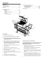
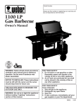
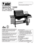
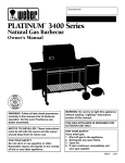
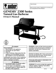
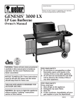
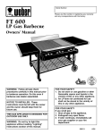
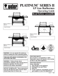
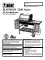
Serial Number Please use this number in registering your warranty and any correspondence with the factory. PLATINUM 3200 Series ™ LP Gas Barbecue Owner's Manual ® National PROPANEGAS Association WARNING: Follow all leak check procedures carefully in this manual prior to barbecue operation. Do this even if barbecue was dealer assembled. NOTICE TO INSTALLER: These instructions must be left with the owner and the owner should keep them for future use. WARNING: Do not try to light this appliance without reading "Lighting" instructions section of this manual. THIS GAS APPLIANCE IS DESIGNED FOR OUTDOOR USE ONLY. FOR YOUR SAFETY 1. Do not store or use gasoline or other flammable vapors and liquids in the vicinity of this or any other appliance. 2. An LP tank not connected for use shall not be stored in the vicinity of this or any other appliance. FOR YOUR SAFETY If you smell gas: 1. Shut off gas to the appliance. 2. Extinguish any open flame. 3. Open lid. 4. If odor continues, immediately call your gas supplier or call your fire department. 98832 12/97 DANGER Failure to follow the Dangers, Warnings and Cautions contained in this Owner’s Manual may result in serious bodily injury or death, or in a fire or an explosion causing damage to property. WARNINGS Do not store a spare or disconnected LP tank under or near this barbecue. Improper assembly may be dangerous. Please carefully follow the assembly instructions in this manual. After a period of storage, and/or nonuse, the Weber Gas Barbecue should be checked for gas leaks and burner obstructions before using. See instructions in this manual for correct procedures. Do not operate the Weber Gas Barbecue if there is a gas leak present. Do not use a flame to check for gas leaks. Combustible materials should never be within 24 inches of the top, bottom, back or sides of your Weber Gas Barbecue. Do not put a barbecue cover or anything flammable on or in the storage area under the cooking box. Your Weber Gas Barbecue should never be used by children. You should exercise reasonable care when operating your Weber Gas Barbecue. It will be hot during cooking or cleaning, and should never be left unattended. Should the burners go out during operation, turn all gas valves off. Open the lid and wait five minutes before attempting to relight, using the lighting instructions. Do not use charcoal or lava rock in your Weber Gas Barbecue. Never lean over open grill or place hands or fingers on the front edge of the cooking box. Should a grease fire occur, turn off all burners and leave lid closed until fire is out. Do not enlarge valve orifices or burner ports when cleaning the valves or burners. The Weber Gas Barbecue should be thoroughly cleaned on a regular basis. LP gas is not natural gas. The conversion or attempted use of natural gas in an LP unit or LP gas in a natural gas unit is dangerous and will void your warranty. Do not attempt to disconnect any gas fitting while your barbecue is in operation. Use heat-resistant barbecue mitts or gloves when operating barbecue. LP GAS UNITS ONLY: Use the regulator that is supplied with your Weber Gas Barbecue. Do not attempt to disconnect the gas regulator or any gas fitting while your barbecue is in operation. A dented or rusty LP tank may be hazardous and should be checked by your liquid propane supplier. Do not use an LP tank with a damaged valve. Although your LP tank may appear to be empty, gas may still be present, and the tank should be transported and stored accordingly. If you see, smell or hear the hiss of escaping gas from the LP tank: 1. Get away from LP tank. 2. Do not attempt to correct the problem yourself. 3. Call your fire department. 2 WARRANTY Weber-Stephen Products Co. (Weber) hereby warrants to the ORIGINAL PURCHASER of this Weber Gas Barbecue that it will be free of defects in material and workmanship from the date of purchase as follows: There are no other express warrants except as set forth herein and any applicable implied warranties of merchantability and fitness are limited in duration to the period of coverage of this express written Limited Warranty. Some states do not allow limitation on how long an implied warranty lasts, so this limitation may not apply to you. Aluminum Castings, 10 years, Cooking Grates and Flavorizer Bars, 3 years, All Remaining Parts, 5 years, Weber is not liable for any special, indirect or consequential damages. Some states do not allow the exclusion or limitation of incidental or consequential damages, so this limitation or exclusion may not apply to you. when assembled and operated in accordance with the printed instructions accompanying it. Weber may require reasonable proof of your date of purchase. THEREFORE, YOU SHOULD RETAIN YOUR SALES SLIP OR INVOICE. Weber does not authorize any person or company to assume for it any other obligation or liability in connection with the sale, installation, use, removal, return, or replacement of its equipment; and no such representations are binding on Weber. This Limited Warranty shall be limited to the repair or replacement of parts which prove defective under normal use and service and which on examination shall indicate, to Weber's satisfaction, they are defective. Before returning any parts, contact your local dealer. If your dealer confirms the defect and approves the claim, Weber will repair or replace such part without charge and return it to you freight or postage prepaid. This Warranty applies only to products sold at retail. WEBER-STEPHEN PRODUCTS CO. Customer Service Center 250 South Hicks Road Palatine, IL, 60067-6241 (800) 446-1071 This Limited Warranty does not cover any failures or operating difficulties due to accident, abuse, misuse, alteration, misapplication, vandalism, improper installation or improper maintenance or service, or failure to perform normal and routine maintenance, including but not limited to damage caused by insects within the burner tubes, as set out in this owner's manual. LP Tank The LP tank manufacturer is responsible for the materials, workmanship and performance of the tank. If the tank has a defect, malfunctions, or you have a question regarding the tank, call the tank manufacturer's customer service center. The phone number is on the warning decal which is permanently attached to the tank. If the tank manufacturer has not resolved the issue to your satisfaction, then call your dealer. Deterioration or damage due to severe weather conditions such as hail, hurricanes, earthquakes or tornadoes, discoloration due to exposure to chemicals either directly or in the atmosphere, is not covered by this Limited Warranty. 3 PATENTS AND TRADEMARKS © 1997 Weber. Weber, , Flavorizer and Crossover are registered U.S. trademarks; Platinum, Perma-Mount, Gas Catcher, FlameCheck, SteamN-Chips, Spider Stopper, and Warm-Up are U.S. trademarks of WeberStephen Products Co., 200 East Daniels Road, Palatine, IL 60067-6266. U.S.A. Genesis Gas Barbecues are covered under the following patent nos.: U.S.A. #4,677,964; 4,727,853; #4,777,927; #4,829,978; #4,860,724; #4,941,817; #4,966,125; #5,070,776; #D293,067; #D316,355; Canada: Rd 1987 Reg. #58,034; #1,279,540; #1,283,586; #1,300,994; #1,300,995. Printed in the U.S.A. 4 Contents WARNINGS ................................................................ 2 Warranty & Patents.................................................. 3-4 General Instructions.................................................... 6 Assembly ............................................................... 7-24 Troubleshooting & Maintenance Annual Maintenance ........................................ 32 General Maintenance.................................. 33-35 Troubleshooting .......................................... 36-37 Parts Listing .............................................................. 39 Operating Instructions Lighting ....................................................... 25-27 Cooking ............................................................ 28 Storage and/or Nonuse .................................... 28 Cleaning ........................................................... 28 LP Tank Information.................................... 29-31 b c e a d f g k FEATURES: j a a) Convenient tables and racks. i h b) Heavy gauge porcelain-on-steel lid seals in heat. c) Rapid read thermometer for precision cooking measures grill temperature, and can be removed and inserted into the food. d) Heavy gauge steel Flavorizer Bars distribute heat within the grill. Flavorizer Bars heat just the right amount of drippings for flavoring, letting excess fat drip past to help prevent flare-ups. IMPORTANT NEW FEATURES: Your Weber Gas Barbecue is equipped with a new and improved LP tank connection, that has additional safety features. They are: e) Weber Warm-Up Basket for additional cooking or warming space. f) 1. The connection of the barbecue to the LP tank can be made without the use of tools. Separate burners for temperature control. 2. The new connection will not permit the flow of gas until a positive gas connection is made. g) Side burner for making sauces, gravies, etc.,while main grill is in use. 3. If an accidental fire occurs at the LP tank connection, the flow of gas is stopped by a temperature activated shutoff. h) Fuel scale indicates LP gas supply. i) j) Crossover Ignition System with Gas Catcher Ignition Chamber. 4. If the LP supply hose becomes damaged, cut, punctured, or accidentally fire damaged, the barbecue connection is equipped with an excess flow control that will limit the flow of gas if leakage or a fire occurs. Catch pan catches excess grease. k) Locking casters for additional portability. 5 General Instructions Storage ■ The gas must be turned OFF at the LP tank when the Weber Gas Barbecue is not in use. ■ When the Weber Gas Barbecue is stored indoors, the gas supply must be disconnected and the LP tank stored outdoors in a well-ventilated space. The Weber Gas Barbecue is portable so you can easily change its location in your yard or on your patio. Portability means you can take your Weber Gas Barbecue with you if you move. ■ LP tanks must be stored outdoors in a well-ventilated area out of the reach of children. Disconnected LP tanks must not be stored in a building, garage or any other enclosed area. Liquid Propane (LP) gas supply is easy to use and gives you more cooking control than charcoal fuel. ■ When the LP tank is not disconnected from the Weber Gas Barbecue, the appliance and LP tank must be kept outdoors in a well-ventilated space. Your Weber Gas Barbecue is a portable outdoor cooking appliance. With the Weber Gas Barbecue you can grill, barbecue, roast and bake with results that are difficult to duplicate with indoor kitchen appliances. The closed lid and Flavorizer Bars produce that "outdoor" flavor in the food. ■ These instructions will give you the minimum requirements for assembling your Weber Gas Barbecue. Please read the instructions carefully before using your Weber Gas Barbecue. Improper assembly can be dangerous. ■ Not for use by children. ■ If there are local codes that apply to portable gas grills, you will have to conform to them. If there are no local codes, you must conform to the latest edition of the National Fuel Gas Code: ANSI Z 223.1. ■ ■ Operating area WARNING: Only use this barbecue outdoors in a well ventilated area. Do not use in a garage, building, breezeway or any other enclosed area. The pressure regulator supplied with the Weber Gas Barbecue must be used. This regulator is set for 10.5 inches of water column (pressure). This Weber Gas Barbecue is designed for use with liquid propane (LP) gas only. Do not use with natural (piped in city) gas. The valves, orifices, hose and regulator are for LP gas only. ■ Do not use with charcoal fuel. ■ Check that the area under the control panel and the bottom tray are free from debris that might obstruct the flow of combustion or ventilation air. ■ The area around the LP tank must be free and clear from debris. For Installation in Canada These instructions, while generally acceptable, do not necessarily comply with the Canadian Installation codes, particularly with piping above and below ground. In Canada the installation of this appliance must comply with local codes and/or Standard CAN/CGA-B149.2 (Installation Code for Propane Burning Appliances and Equipment). 6 ■ Never use your Weber Gas Barbecue under an unprotected combustible roof or overhang. ■ Your Weber Gas Barbecue is not intended to be installed in or on recreational vehicles and/or boats. ■ Do not use combustible materials within 24 inches of the top, bottom, back or sides of the grill. ■ The entire cooking box gets hot when in use. Do not leave unattended. ■ Keep any electrical supply cord and the fuel supply hose away from any heated surface. ■ Keep the cooking area clear of flammable vapors and liquids, such as gasoline, alcohol, etc., and combustible materials. ■ Never store an extra (spare) LP tank under or near the Weber Gas Barbecue. Assembly Step 1 Check package contents Tools needed Screwdrivers, regular Cooking box (assembly) and Phillips Hammer 7/16, 5/8, 11/16, and 3/4 inch open-end or two adjustable wrenches Lid (assembly) Pliers Block of wood LP tank Supplies needed Your LP tank is shipped empty for safety. After setting the LP fuel scale you will need to fill it. (See Step "Fill LP tank.") You will need a soap and water solution to check for gas leaks. (See Step "Check for gas leaks.") Filler adapter Note - The hardware size of nuts, bolts and screws is given. For example "1/4-20 x 2 inch bolt" means a bolt 1/4 inch in diameter with 20 threads to the inch, 2 inches long. On a small screw for example, "6-32 x 1/2 inch screw" means a number 6 screw, with 32 threads to the inch, 1/2 inch long. Bottom tray Work table Two accessory trays Two swing tables 7 ® ® Control panel Two casters Front panel Two cooking grates Left frame Warming rack Wheel frame Warm-Up Basket Two frame connectors Thermometer Tank panel assembly Left hand slide bar assembly Five long Flavorizer Bars Assembly consists of: Left hand slide bar Two wheels Support WE BE R WE B E R Eight short Flavorizer Bars Slide Two aluminum drip pans Catch pan Right hand slide bar assembly Axle Assembly consists of: Right hand slide bar Spacer bracket Support Right frame Slide Caster frame 8 Fuel scale assembly Two wheel hubcaps (actual size) Two hinge pins (hardware size: 1/4 x 1 1/2 inch clevis pin) (actual size) Catch pan holder Five 1/4-20 x 2 inch bolts (actual size) Manifold bracket Six 1/4-20 x 1/2 inch bolts (actual size) Side burner assembly Two 1/4-20 wing nuts (actual size) Burner grate Four 10-24 x 1 3/4 machine screws (actual size) Side burner knob Four 10-24 hex nuts (actual size) Twenty-two 1/4 inch nylon washers (actual size) Two side burner locks 1/4-20 keps nut Check contents of hardware packs 1/4-20 x 1 1/4 inch bolt (actual size) Three burner control knobs 1/4-20 hex nut (actual size) Three tool holders Two hair pin cotters Four tubing plugs (two are spares) Two swing table end brackets Two Phillips screws/washers 9 Step 3 Assemble wheels Assemble frame You will need: axle, two wheel hubcaps, two wheels, wheel frame, hammer and a block of wood. You will need: left frame, right frame, two nylon washers, two 1/4-20 x 1/2 inch bolts and a 7/16 inch wrench. Place one end of the axle on the block of wood (or other protected surface). Tap on one hubcap. Note - Work on carpeted area (on grass, or on one of the boxes) to protect the finish during frame assembly. Put one wheel on the axle, WEBER side toward the hubcap. Slide the axle through the frame. Add the other wheel, WEBER side out. Tap on the hubcap. Figure 1. Put the frame pieces so the leg tabs are up. Put the right frame to your right and left frame to your left. Figure 2. Slip the two frame halves together with the tabs inside, until the tabs of the right frame are inside the left frame and the holes align. Figure 2 (a). WE BE WE B E R Step 2 R Slip washers over bolts; insert and tighten bolts. (If you try to insert a bolt and there are no holes, you have the left frame turned the wrong way. Turn the left frame around.) Figure 2 (b). (a) Figure 1 Frame tabs Leg tabs Right frame Left frame (b) Figure 2 10 Step 4 Step 5 Continue frame assembly Complete frame assembly You will need: frame assembly, wheel frame assembly, front panel, caster frame, four 1/4-20 x 1/2 inch bolts, four nylon washers and a 7/16 inch wrench. You will need: partial frame assembly, two frame connectors, four 1/4-20 x 2 inch bolts, four nylon washers and a 7/16 inch wrench. Place the caster frame onto the tabs of the left frame with the dimple to the inside. Figure 3. Place the wheel frame onto the tabs of the right frame with the dimple to the inside. The fuel scale decal should face away as shown. Figure 3. Hold one frame connector between the caster and wheel frame. Add the nylon washer to the bolt. Put the bolt through the frame and screw into frame connector. Tighten. Repeat procedure with the other frame connector. Figure 4. The leg tabs must be on the inside of the frames. Add front panel with the hole down and to your right. Add the washers to the bolts, insert in the holes as shown. Only start the bolts at the wheel frame, figure 3 (a) & (b), and tighten the bolts at the caster frame. Note - Fuel scale decal on wheel frame must be on the same side as the front panel. Caster frame Dimples to the inside Wheel frame Figure 4 Fuel scale decal Step 6 Insert casters (b) (a) You will need: frame assembly and two casters. Push the casters firmly into the inserts in the ends of the caster legs. Figure 5. Only start this bolt Figure 3 Figure 5 11 Step 7 Step 8 Install side burner locks Add cooking box You will need: frame assembly, two side burner locks and a 7/16 inch wrench. You will need: frame assembly, cooking box assembly, spacer bracket, 1/4-20 x 2 inch bolt, nylon washer, 1/4-20 keps nut, pliers and a 7/16 inch wrench. Loosen the right rear 1/4 x 20 bolt. Install the side burner lock. The “U” shape cut out of the lock slips down over the bolt. Tighten with a wrench. Figure 6 (a). Uncoil the hose. Set the cooking box into the frame so the burner tubes are under the frame brace. Figure 7. Loosen the right front 1/4 x 20 bolt. The side burner lock fits between the front panel and the frame. The “U” shape cut out slips up over the bolt. Tighten with a wrench. Figure 6 (b). Burner tubes Frame brace (a) (b) Figure 7 Slide the cooking box to the left within the frame. Put the washer on the bolt. Take the spacer bracket and hold it up to the frame making sure both tabs fit underneath the frame cross piece. Figure 8 (a). Insert the bolt through the center hole in the spacer bracket, frame and cooking box with the head of the bolt outside the spacer bracket. Figure 8 (b). Add the keps nut. Figure 8. Tighten by holding the bolt with pliers while you tighten the nut with a wrench. Figure 6 (a) Spacer bracket Keps nut (b) Bolt Nylon washer Figure 8 12 Frame cross piece Your Weber Gas Barbecue burner assembly has been factory assembled, pressure and flame tested. As a safety precaution we recommend you check the burner alignment: Step 9 a) Do the valves fit into the ends of the burners? Figure 9 (a). You will need: tank panel assembly, 1/4-20 x 1 1/4 inch bolt, 1/4-20 hex nut, nylon washer and a 7/16 inch wrench. b) Are the ends of the burners under the washers at the left rear and left front of the cooking box? The screws are only guides. Do not tighten. Figure 9 (b). Insert the tank panel tabs into the slots in the frame brace. Slide up until the notch at the bottom of the tank panel fits over the cross brace. Figure 10 (a). c) Are the wing nuts under the burner assembly hand tight? Do not tighten with pliers. Figure 9 (c). Add the washer to the bolt. Put the bolt through panel and frame brace, add hex nut and tighten with the 7/16 inch wrench. Figure 10 (b). Install tank panel assembly If you answered YES to a, b and c, the burners are correctly aligned. If you answered NO, the burners are misaligned. Contact your dealer. Do not use your barbecue. Slot in frame brace (a) Guide screw Frame brace (b) (a) Tabs on tank panel (c) (b) Figure 10 Figure 9 Cross brace Wing nuts 13 Step 10 Step 11 Add fuel scale Install igniter You will need: fuel scale assembly, two 1/4-20 wing nuts and two nylon washers. Note - The igniter wires are already attached to the Gas Catcher Ignition Chamber and the igniter. This was done to factory test the ignition system. Slip the bolts on the back of the fuel scale assembly through the two small holes in the tank panel. Add washers, then wing nuts and tighten. Figure 11. The igniter lock nut is on the igniter. Route the igniter and wires as shown. Figure 12 (a). Insert the top of the igniter up through the large part of the keyhole in the frame brace. Figure 12 (b). Loosen the igniter lock nut and slide the igniter to the small part of the keyhole. Figure 12 (c). Tighten the igniter lock nut. Note - If the igniter works loose, carefully tighten the igniter lock nut with an adjustable wrench or pliers. Figure 11 (a) E E (b) F F Figure 12 View from front left View from front right (c) Keyhole in frame brace Frame brace 14 Small part of keyhole in frame brace Igniter lock nut Step 12 Step 13 Check that all burner valves are off Install side burner You will need: one burner control knob. You will need: side burner assembly, burner grate, and manifold bracket. (Valves are shipped in the OFF position, but you should check to be sure.) Put the knob on each valve. Check by pushing down and turning clockwise. If they do not turn, they are off, proceed to the next step. Figure 13. WARNING: Make sure gas supply is OFF. Slide the side burner assembly into the open end of the right frame. Route the side burner hose around the tank panel so it will not interfere with scale indicator rod. The side burner hose is connected in the following manner: Slide back the collar of the quick disconnect on the manifold. Push the male fitting of the side burner hose into the quick disconnect, and maintain pressure. Slide the collar closed. Figure 14 (a). Figure 14 (b) shows the quick disconnect engaged. Install burner grate. Check to be sure the side burner valve is OFF. Push side burner control knob down and turn clockwise. Figure 14. Figure 13 Figure 14 Male fitting of side burner a) Manifold side view Quick disconnect engaged b) Side burner hose 15 Manifold side view Step 14 Step 15 Install manifold bracket Set LP fuel scale You will need: manifold bracket You will need: LP tank (empty). Hook the bracket onto the manifold at the center burner valve. Figure 15. Place your hand underneath the bracket. Lift the bracket, manifold and cooking box slightly as a unit and hook onto the frame brace. Note - For accuracy, the fuel scale must be set with an empty tank. We utilize various LP tank manufacturers. Some of the tanks we receive have differing top collar assemblies. (The top collar is the metal protective ring around the valve.) One series of tanks mounts with the valve facing the front. The other tanks mount with the valve facing away from the fuel scale. These types of tanks are illustrated in Figure 16. Manifold bracket Frame brace Loosen the tank lock wing nut. Tighten so the lock is held up out of the way. Figure 16 (a). Lift and hook the tank onto the fuel scale. With an empty LP tank, adjust the fuel scale setting to E by turning the scale setting (top) wing nut. Figure 16 (b). CAUTION: Do not remove adjustment wing nut from tank scale. Figure 15 After adjusting tank scale, push tank down a couple of times to check that the tank scale is set on “E”. Scale setting wing nut Tank lock wing nut (a) (b) E E F F Figure 16 Step 16 Fill LP tank Note - The LP tank manufacturer is responsible for the materials, workmanship and performance of the tank. If the tank has a defect, malfunctions, or you have a question regarding the tank, call the tank manufacturer's customer service center. The phone number is on the warning decal which is permanently attached to the tank. If the tank manufacturer has not resolved the issue to your satisfaction, then call Weber-Stephen Products Co., Customer Service Center. 16 To fill, take the LP tank and filler adapter to an RV center or look gas-propane in the phone book for other sources of LP gas. The hose and regulator are connected in the following manner: Slide back the collar of the quick disconnect on the tank valve. Push the male fitting of the regulator into the quick disconnect, and maintain pressure. Slide the collar closed. Figure 18 (a). Figure 18 (b) shows the quick disconnect engaged and various components of the tank and regulator. Regulator vent hole should be at 3, 6, or 9 o'clock. It should not be pointed up. Figure 18 (c). WARNING: We recommend that your LP tank be filled at an authorized LP gas dealer by a qualified attendant, who fills the tank by weight. IMPROPER FILLING IS DANGEROUS. Tell your LP dealer that this is a new LP tank. The air must be removed from a new LP tank before the initial filling. Your LP gas dealer is equipped to do this. WARNING: If you exchange your LP tank, make sure you get a similar tank in return. Your LP tank is equipped with a quick-disconnect valve and an OPD (Overfilling Prevention Device). Other LP tanks are not compatible with your barbecue connection. (a) Collar The LP tank must be installed, transported and stored in an upright position. LP tank should not be dropped or handled roughly. Male fitting Never store or transport the LP tank where temperatures can reach 125° Fahrenheit (too hot to hold by hand – for example: do not leave the LP tank in a car on a hot day). For full instructions for safe handling of LP tanks see section "Operating Instructions". (b) Hose Note - Remove LP tank filler adapter before connecting the regulator to the tank. Tank valve Regulator Step 17 Valve handwheel close clockwise Pressure relief valve Connect LP tank WARNING: Make sure that the LP tank valve is closed. Close by turning clockwise. Tank Hook the LP tank onto the fuel scale. Loosen the tank lock wing nut. Swing the tank lock down. Tighten the wing nut. Figure 17. Regulator vent Tank lock wing nut E Quick disconnect engaged (c) F Turn so regulator vent does not collect water Figure 17 Figure 18 17 Step 18 WARNING: Do not ignite burners while leak checking. Check for gas leaks Check for leaks by wetting the connections with the soap and water solution and watching for bubbles. If bubbles form or if a bubble grows there is a leak. DANGER Check: Do not use an open flame to check for gas leaks. Be sure there are no sparks or open flames in the area while you check for leaks. This will result in a fire or explosion which can cause serious bodily injury or death and damage to property. a) Hose to manifold connection. Figure 21 (a). b) Regulator to tank connection. Figure 21 (b). c) Manifold to side burner hose connection. Figure 21 (c). WARNING: If there is a leak at connections a, b or c, retighten the fitting and recheck for leaks with soap and water solution. WARNING: You should check for gas leaks every time you disconnect and reconnect a gas fitting. If a leak persists after retightening the fitting, turn OFF the gas. DO NOT OPERATE THE BARBECUE. Contact your dealer. Note - All factory made connections have been thoroughly checked for gas leaks. The burners have been flame tested. As a safety precaution you should recheck all fittings for leaks before using your Weber Gas Barbecue. Shipping and handling may have loosened or damaged a gas fitting. d) Side burner hose to side burner connection. Figure 21 (d). e) Valves to manifold connections. Figure 21 (e). f) WARNING: Perform these leak checks even if your barbecue was dealer or store assembled. Hose to regulator connection. Figure 21 (f). WARNING: If there is a leak at connections d, e or f, turn OFF the gas. DO NOT OPERATE THE BARBECUE. Contact your dealer. You will need: a soap and water solution and a rag or brush to apply it. When leak checks are complete, turn gas supply OFF at the source and rinse connections with water. Note - Since some leaks test solutions, including soap and water, may be slightly corrosive, all connections should be rinsed with water after checking for leaks. (a) (b) Make sure side burner is OFF. Remove valve control knob and screws. Remove porcelain top. Figure 19. (c) Figure 19 To perform leak checks: open tank valve by turning the tank valve handwheel counterclockwise. Figure 20. (d) E (f) (e) F Figure 20 Figure 21 18 Step 19 Step 20 Install Flavorizer Bars and Cooking Grates Install the bottom tray You will need: five long Flavorizer Bars, eight short Flavorizer Bars and two cooking grates. You will need: bottom tray, catch pan holder, catch pan and one drip pan. Set the long Flavorizer Bars side to side in the lower position, then set the short Flavorizer Bars front to back in the upper position in the cooking box. Figure 22. Finger grip on front edge of bottom tray Front side of catch pan holder Figure 24 Hook the ends of the catch pan holder into the hole in the bottom tray. Figure 25. The front of the catch pan holder must be on the same side as the finger grip of the bottom tray. Figure 22 The open "U" of the cooking grates goes down. Set the cooking grates onto the ledges in the cooking box. Figure 23. Finger grip Figure 25 Slide the bottom tray onto the mounting rails under the cooking box with finger grip toward you. Figure 26. CAUTION: Do not line bottom tray with aluminum foil. It can cause grease fires by trapping the grease and not allowing grease to flow into the catch pan. Figure 23 Bottom tray Figure 26 Put the foil drip pan into the catch pan. Slide the catch pan into the catch pan holder with its finger grip towards you. 19 Step 21 Step 22 Install the lid You will need: lid, two hinge pins and two hair pin cotters. Install tool holders, control panel and burner control knobs Set the lid in place. Align the hinges at the rear of the barbecue. Insert hinge pins from the outside. Insert hair pin cotters into the small holes in the hinge pins. Figure 27. You will need: three tool holders, control panel, two Phillips screws/washers, a Phillips screwdriver, and three burner control knobs. Hook the tool holders over the frame rail. Figure 28. Set the control panel in place over both frame braces. (Hold the Crossover Ignition button up while setting the control panel in place.) Line up the holes in the control panel with the holes in the inserts in the frame brace. Insert screws and tighten with a Phillips screwdriver until snug. Do not overtighten. Figure 28 (a). Hair pin cotter Hinge pin Push on the burner control knobs. Figure 28 (b). Insert in frame brace (a) Crossover Ignition Button Figure 27 Control panel Phillips screws/ washers (b) Tool holders Figure 28 20 Step 23 Step 24 Secure side burner Install left hand swing table Pull the right hand swing table up. Stand to the right side of the barbecue. Slightly pull back both side burner locks. Slide the side burner toward the control panel. The locks will snap into the slots in the front and back of the side burner. Figure 29. You will need: swing table end bracket, two 10-24 hex nuts, two 10-24 x 1 3/4 inch machine screws, left hand slide bar assembly, swing table, four nylon washers, screwdriver and pliers. Allow the slide bar to hang down. Push the support rod into the lower support bracket. Figure 30 (a). Swing the rod up so you can slide the rod all the way inside the locking tab. Figure 30 (b). The rod should swing freely inside the locking tab. Figure 30 (c). CAUTION: Make sure both locks have snapped into place. (b) (c) Support rod View from top (a) Figure 30 Side view Figure 29 21 Insert one end of the hinge rod into the hole in the frame. Figure 31 (a). Position slide bar assembly on the outside of the caster frame. Put a nylon washer on each 1 3/4 inch screw, insert screws through frame and slide bar assembly and add nylon washers and hex nuts. Tighten nuts using a screwdriver and pliers. Figure 32. Insert the other end into the hole in the swing table end bracket. Figure 31 (b). Hold the end bracket at an angle so the lower tab is inside the frame tube. Push the bracket into the frame. Check to see that the lower tab of the bracket is hooked in the slot in the frame. Figure 31 (c). Notch to the front To fully seat the bracket, you may have to tap it lightly with a hammer. Slide bar WARNING: If swing table end bracket is in any way cracked or damaged, do not use swing table. Call your dealer to order a new part. WARNING: The load limit for the swing table is 30 pounds. Hinge rod (a) View from front of barbecue (b) Figure 32 To lower table: Pull support rod up to disengage slide lock, and lower table. To raise table, lift table up and engage slide in locked position. Figure 33. View from rear of barbecue Support rod (c) View from rear of barbecue Slide Figure 31 Slot in frame (view from below) Unlocked position Locked position Figure 33 22 Step 25 Insert one end of the hinge rod into the hole in the frame. Figure 35 (a). Install right hand swing table Insert the other end into the hole in the swing table end bracket. Figure 35 (b). Hold the end bracket at an angle so the lower tab is inside the frame tube. Push the bracket into the frame. Check to see that the lower tab of the bracket is hooked in the slot in the frame. Figure 35 (c). You will need: swing table end bracket, two 10-24 hex nuts, two 10-24 x 1 3/4 inch machine screws, right hand slide bar assembly, swing table, four nylon washers, screwdriver and pliers. Allow the slide bar to hang down. Push the support rod into the lower support bracket. Figure 34 (a). Swing the rod up so you can slide the rod all the way inside the locking tab. Figure 34 (b). The rod should swing freely inside the locking tab. Figure 34 (c). To fully seat the bracket, you may have to tap it lightly with a hammer. WARNING: If swing table end bracket is in any way cracked or damaged, do not use swing table. Call your dealer to order a new part. View from rear (b) WARNING: The load limit for the swing table is 30 pounds. (c) (a) (b) Support rod Hinge rod (a) View from rear of barbecue Slide bar assembly Figure 34 (c) Figure 35 Slot in frame (view from below) 23 Step 26 Position slide bar assembly on the outside of the wheel frame. Put a nylon washer on each 1 3/4 inch screw, insert screws through wheel frame and slide bar assembly and add nylon washers and hex nuts. Tighten nuts using a screwdriver and pliers. Figure 36. Complete accessory installation You will need: work table, two accessory trays, Warm-Up Basket, warming rack, thermometer, two tubing plugs and a hammer. Notch F Insert one end of the Weber Warm-Up Basket into the hole in the right end of the lid and the other end into the slot in the left end of the lid. Figure 38 (a). Slide bar Set the work table onto the left side rails. Figure 38 (b). Set the accessory trays between the two frame connectors. Figure 38 (c). F Open the lid and set the warming rack into the slots at the rear of the cooking box. Figure 38 (d). Insert the thermometer into its holder. Figure 38 (e). View from front of barbecue Insert tubing plugs into the ends of the frame. To fully seat the plugs, you may have to tap them lightly with a hammer. Figure 38 (f). Wheel frame Figure 36 To lower table: Pull support rod up to disengage slide lock and lower table. To raise table, lift table up and engage slide in locked position. Figure 37. (a) Support rod (d) (e) (b) (f) (c) Slide Figure 38 CAUTION: To keep the barbecue stationary, the tabs on the locking casters should be in the down position. Unlocked position Locked position Figure 37 24 OPERATING INSTRUCTIONS Lighting WARNING: The burner control knobs must be in the OFF position before turning on the LP tank valve. If they are not in the OFF position, when you turn on the LP tank valve, the excess flow control will activate, limiting the flow of gas from the LP tank. If this should occur, turn OFF the LP tank valve and burner control knobs and start over. Summary lighting instructions are on the control panel. DANGER Failure to open lid while igniting the barbecue, or not waiting 5 minutes to allow the gas to clear if the barbecue does not light, may result in an explosive flame-up which can cause serious bodily injury or death. DANGER When the excess flow control is activated, a small amount of gas is still flowing to the burners. After turning OFF the tank and burner control knobs, wait at least 5 minutes for the gas to clear before attempting to light the barbecue. Failure to do so may result in an explosive flame-up which can cause serious bodily injury or death. Crossover Ignition System Note - The Crossover Ignition System ignites the Front burner with a spark from the igniter electrode inside the Gas Catcher Ignition Chamber. You generate the energy for the spark by pushing the Crossover Ignition Button until it clicks. WARNING: Check hose before each use of barbecue for nicks, cracking, abrasions or cuts. If the hose is found to be damaged in any way, do not use the barbecue. Replace the manifold assembly, which includes the gas hose. Call your dealer for the necessary parts. 4) Turn the tank on by turning the tank valve counterclockwise. WARNING: Do not lean over open barbecue. Keep your face and body at least one foot away from the matchlight hole when lighting the barbecue. Crossover Ignition System 1 5) Push Front burner control knob down and turn to START/HI. 6) Push the Crossover Ignition Button several times, so it clicks each time. 3 8 7) Check that the burner is lit through the matchlight hole on the front of the cooking box. WARNING: If the burner does not light, turn the Front burner control knob to OFF and wait 5 minutes to let the gas clear before you try again or try to light with a match. 4 7 5 6 2 8) After the FRONT burner is lit you can turn on the other burners. Figure 1 Note - Always light the FRONT burner first. The other burners ignite from the FRONT burner. 1) Open the lid. Figure 1. 2) Check that the fuel scale reads more than “E”. Note - E = empty; F = full. To Extinguish 3) Make sure all burner control knobs are OFF. (Push each burner control knob down and turn clockwise.) Turn gas supply OFF at the source, then push down and turn each burner control knob clockwise to OFF. 25 Manual Lighting 4) Turn the tank on by turning the tank valve counterclockwise. DANGER 5) Strike a match and put the flame into the matchlight hole in the front of the cooking box. Failure to open lid while igniting the barbecue, or not waiting 5 minutes to allow the gas to clear if the barbecue does not light, may result in an explosive flame-up which can cause serious bodily injury or death. WARNING: Do not lean over open barbecue. Keep your face and body at least one foot away from the matchlight hole when lighting the barbecue. 6) Push Front burner control knob down and turn to START/HI. 7) Check that the burner is lit by looking through the matchlight hole on the front of the cooking box. 1) Open the lid. Figure 2. WARNING: If the burner does not light, turn the Front burner control knob to OFF and wait 5 minutes to let the gas clear before you try again or try to light with a match. 2) Check that fuel scale reads more than “E”. Note - E = empty; F = full. 3) Make sure all burner control knobs are OFF. (Push each burner control knob down and turn clockwise.) 8) After the FRONT burner is lit you can turn on the other burners. WARNING: The burner control knobs must be in the OFF position before turning on the LP tank valve. If they are not in the OFF position, when you turn on the LP tank valve, the excess flow control will activate, limiting the flow of gas from the LP tank. If this should occur, turn OFF the LP tank valve and burner control knobs and start over. Note - Always light the FRONT burner first. The other burners ignite from the FRONT burner. To Extinguish Turn gas supply OFF at the source, then push down and turn each burner control knob clockwise to OFF. DANGER When the excess flow control is activated, a small amount of gas is still flowing to the burners. After turning OFF the tank and burner control knobs, wait at least 5 minutes for the gas to clear before attempting to light the barbecue. Failure to do so may result in an explosive flame-up which can cause serious bodily injury or death. Manual Lighting 1 3 8 4 7 5 6 2 Figure 2 26 Lighting the side burner Lighting the side burner if the main burners are lit. Figure 4. The side burner has a separate ignition system from the main cooking box. 1) Open the side burner lid. 2) Push down and turn the side burner control to HI. DANGER 3) Press the side burner igniter button several times so it clicks each time. Failure to open lid while igniting the barbecue, or not waiting 5 minutes to allow the gas to clear if the barbecue does not light, may result in an explosive flame-up which can cause serious bodily injury or death. 1 2 Lighting only the side burner. Figure 3. 3 1) Open the side burner lid. Figure 4 2) Check that the fuel scale reads more than “E”. 3) Check that the side burner valve is OFF (push down and turn clockwise), and all main burner control valves are OFF (push down and turn clockwise). CAUTION: Side burner flame may be difficult to see on a bright sunny day. 4) Turn the LP tank valve on (turn counterclockwise). a) 5) Push down and turn the side burner control valve to HI. b) Wait 5 minutes to let the gas clear before you try again or try to light with a match. WARNING: If the side burner does not light: 6) Push the side burner igniter button several times so it clicks each time. 1 5 3 6 Figure 3 CAUTION: Side burner flame may be difficult to see on a bright sunny day. WARNING: If the side burner does not light: a) Turn OFF the side burner control valve. b) Wait 5 minutes to let the gas clear before you try again or try to light with a match. 27 Turn OFF the side burner control valve. Cooking Storage and/or Nonuse continued WARNING: Do not move the Weber Gas Barbecue when operating or hot. You can adjust the FRONT, CENTER and BACK burners as desired. The control settings High (H), Medium (M), Low (L), or Off (O) are described in your Weber cookbook. The cookbook uses these notations to describe the settings of the FRONT, CENTER, and BACK burners. For example, to sear steaks you would use (HHH) (all burners at high). Then to complete cooking you would use (MOM) (FRONT at medium, CENTER off, and BACK at medium). See your Weber cookbook for detailed cooking instructions. ■ When the LP tank is not disconnected from the Weber Gas Barbecue, the appliance and LP tank must be kept outdoors in a well-ventilated space. ■ The Weber Gas Barbecue should be checked for gas leaks and any obstructions in the burner tubes before using. (See Sections "General and Annual Maintenance.") ■ Check that the areas under the control panel and the bottom tray are free from debris that might obstruct the flow of combustion or ventilation air. ■ The Spider Stopper Guards should also be checked for any obstructions. (See Section "Annual Maintenance.") Note: The temperatures inside your cooking box, for the first few uses, while surfaces are still very reflective, may be hotter than those shown in your cookbook. Cooking conditions may require the adjustment of the burner controls to attain the correct cooking temperatures. Periodic Cleaning CAUTION: Replace thermometer in lid when not in use. Do not leave thermometer in food while cooking. WARNING: Turn your Weber Gas Barbecue OFF and wait for it to cool before cleaning. If burners go out during cooking, open lid, turn off all burners and wait 5 minutes before relighting. CAUTION: Do not clean your Flavorizer Bars or cooking grates in a self-cleaning oven. Preheating - Your Weber Gas Barbecue is an energy efficient appliance. It operates at a low B.T.U. rate for economy. To preheat, after lighting, close lid and turn all burners to high (HHH). Preheating to between 500° and 550° F (260° and 290° C) will take 10 to 15 minutes depending on conditions such as air temperature and wind. Outside surfaces - Use a warm soapy water solution. Rinse well after cleaning. CAUTION: Do not use oven cleaner, abrasive cleansers (kitchen cleansers) cleaners that contain citrus products or abrasive cleaning pads on barbecue or cart surfaces. Drippings and grease - The Flavorizer Bars are designed to "smoke" the right amount of drippings for flavorful cooking. Excess drippings and grease accumulate in the catch pan under the bottom tray. Disposable foil liners are available that fit the catch pan. Bottom tray - Remove excess grease and then wash with warm soapy water. Rinse well after cleaning. Flavorizer Bars and Cooking Grates- Clean with a suitable brass bristle brush. As needed, remove from grill and wash with warm soapy water. Rinse well after cleaning. WARNING: Check the bottom tray for grease buildup before each use. Remove excess grease to avoid a grease fire in the bottom tray. Catch pan - Disposable foil trays are available, or you can line the catch pan with aluminum foil. To clean the catch pan, wash with warm soapy water. Rinse well after cleaning. Thermometer - Wipe with warm soapy water, clean with plastic scrub ball. Do not put in dishwasher or submerge in water. Storage and/or Nonuse ■ The gas must be turned off at the LP tank when the Weber Gas Barbecue is not in use. ■ When the Weber Gas Barbecue is stored indoors, the gas supply must be DISCONNECTED and the LP tank stored outdoors in a well-ventilated space. ■ LP tanks must be stored outdoors in a well- ventilated area out of reach of children. Disconnected LP tanks must have the dust cover in place and must not be stored in a building, garage or any other enclosed area. Inside cooking box - Brush with a suitable barbecue brush (brass bristle). Brush any debris off of burners with barbecue brush. DO NOT ENLARGE BURNER PORTS (OPENINGS). Wash inside box with warm soapy water. Rinse well after cleaning. Inside Lid - While lid is warm, wipe inside with paper towel to prevent flaking due to grease build-up. Work tables and accessory trays - Use any household cleaners on these surfaces except those that contain acid, mineral spirits or Xylene. Rinse well after cleaning. 28 Refilling the LP tank Connecting the filled LP tank WARNING: Make sure that the LP tank valve is closed. Close by turning clockwise. We recommend that you refill before the scale indicator reaches "E". DANGER Note - If you run out of fuel, check the indicator setting and/or adjust the fuel scale indicator setting with the scale setting wing nut while the tank is empty so you do not run out again. Do not use an open flame to check for gas leaks. Be sure there are no sparks or open flames in the area while you check for leaks. This will result in a fire or explosion which can cause serious bodily injury or death and damage to property. Removal of the LP tank 1) Close tank valve (turn clockwise). Figure 5 (a). 2) Slide the collar back on the quick disconnect to disengage the fitting. Figure 5 (b). 3) Loosen tank lock wing nut and turn tank lock up out of the way. You will need: LP tank, a soap and water solution and a rag or brush to apply it. 4) Lift tank off. Note - Since some leak test solutions, including soap and water, may be slightly corrosive, all connections should be rinsed with water after checking for leaks To refill take LP tank and tank filler adapter to a "Gas Propane" dealer. a) Lift and hook the tank onto the fuel scale. WARNING: We recommend that your LP tank be filled at an authorized LP gas dealer, by a qualified attendant, who fills the tank by weight. IMPROPER FILLING IS DANGEROUS. b) Loosen the tank lock wing nut. Swing the tank lock down. Tighten the wing nut. Figure 6. WARNING: If you exchange your LP tank, make sure you get a similar tank in return. Your LP tank is equipped with a quick-disconnect valve and an OPD (Overfilling Prevention Device). Other LP tanks are not compatible with your barbecue connection. Scale setting wing nut Tank lock wing nut Figure 6 (a) Tank valve Collar (b) Figure 5 29 c) Connect the hose to the tank. Slide back the collar of the quick disconnect on the tank valve. Figure 7 (a). Push the male fitting of the regulator into the quick disconnect, and maintain pressure. Slide the collar closed. Figure 7 (b). If it does not engage or lock, repeat procedure. Gas will not flow unless the quick disconnect is properly engaged. f) Check for leaks by wetting the fitting with the soap and water solution and watching for bubbles. If bubbles form or if a bubble grows there is a leak. If leak does not stop, turn off the gas and contact Weber-Stephen Customer Service. Do not use the barbecue. g) When leak checks are complete, turn gas supply OFF and rinse connections with water. (a) LP Tank The LP tank manufacturer is responsible for the materials, workmanship and performance of the tank. If the tank has a defect, malfunctions, or you have a question regarding the tank, call the tank manufacturer's customer service center. The phone number is on the warning decal which is permanently attached to the tank. If the tank manufacturer has not resolved the issue to your satisfaction, then call Weber-Stephen Products Co., Customer Service Center. Male fitting Regulator Collar (b) Quick disconnect Figure 7 engaged d) Mix soap and water. e) Open the tank valve. Figure 8. Figure 8 30 Safe handling tips for LP Gas ■ Liquid Propane (LP) Tank(s) Liquid Propane (LP) gas is a petroleum product as are gasoline and natural gas. LP gas is a gas at regular temperatures and pressures. Under moderate pressure, inside a tank, LP gas is a liquid. As the pressure is released the liquid readily vaporizes and becomes gas. ■ LP gas has an odor similar to natural gas. You should know this odor. ■ LP gas is heavier than air. Leaking LP gas may collect in low areas that prevent dispersion. ■ To fill, take the LP tank to an RV center, or look up gaspropane in the phone book for other sources of LP gas, to fill the tank with 20 pounds of liquid propane. ■ The LP tank and connections supplied with your Weber Gas Barbecue have been designed and tested to meet government, American Gas Association and Underwriters Laboratories requirements. ■ Replacement LP tanks supplied by Weber satisfy the requirements. Check to be sure the tank has a D.O.T. certification, and has been tested within five years. Your LP gas supplier can do this for you. Figure 9. If you have questions about spare LP tanks, please call Weber-Stephen Customer Service. D.O.T. Certification (example) WARNING: We recommend that your LP tank be filled at an authorized LP gas dealer, by a qualified attendant, who fills the tank by weight. IMPROPER FILLING IS DANGEROUS. DOT 4BA240 1/97 2/96 WARNING: If you exchange your LP tank, make sure you get a similar tank in return. Your LP tank is equipped with a quick-disconnect valve and an OPD (Overfilling Prevention Device). Other LP tanks are not compatible with your barbecue connection. ■ Air must be removed from a new LP tank before the initial filling. Your LP dealer is equipped to do this. ■ The LP tank must be installed, transported and stored in an upright position. LP tanks should not be dropped or handled roughly. ■ Never store or transport the LP tank where temperatures can reach 125° F (too hot to hold by hand - for example: do not leave the LP tank in a car on a hot day). 20 lb LP tank Figure 9 Note - A refill will last about 20 hours of cooking time at normal use. The fuel scale will indicate the propane supply so you can refill before running out. You do not have to run out before you refill. ■ Treat "empty" LP tanks with the same care as when full. Even when the LP tank is empty of liquid there still may be gas pressure in the tank. Always close the tank valve before disconnecting. ■ Do not use a damaged LP tank. Dented or rusty LP tanks or LP tanks with a damaged valve may be hazardous and should be replaced with a new one immediately. See "LP tank requirements". ■ The joint where the hose connects to the LP tank must be leak tested each time the LP tank is reconnected. For example, test each time the LP tank is refilled. ■ Be sure the regulator is mounted with the small vent hole pointed downward so it will not collect water. This vent should be free of dirt, grease, bugs etc. Date Tested 31 ■ All LP tank supply systems must include a collar to protect the tank valve. ■ The LP tank must be a 20 lb size (18 1/4 inches high, 12 1/4 inches in diameter). ■ The LP tank must be constructed and marked in accordance with the specifications for LP gas cylinders of the U.S. Department of Transportation (D.O.T.). WARNING: If there is a leak at connections a, b or c, retighten the fitting and recheck for leaks with soap and water solution. Annual Maintenance After a period of nonuse we recommend that you perform the following maintenance procedures for your safety. If a leak persists after retightening the fitting, turn OFF the gas. DO NOT OPERATE THE BARBECUE. Contact your dealer. WARNING: Check hose before each use of barbecue for nicks, cracking, abrasions or cuts. If the hose is found to be damaged in any way, do not use the barbecue. Replace the manifold assembly, which includes the gas hose. Contact your dealer for the necessary parts. ■ ■ d) Side burner hose to side burner connection. Figure 10 (d). e) Valves to manifold connections. Figure 10 (e). f) Inspect the burners for correct flame pattern. Clean if necessary, following the procedures outlined in the "General Maintenance" section of this manual. Hose to regulator connection. Figure 10 (f). WARNING: If there is a leak at connections d, e or f, turn OFF the gas. DO NOT OPERATE THE BARBECUE. Contact your dealer. Check all gas fittings for leaks. When leak checks are complete, turn gas supply OFF at the source and rinse connections with water. DANGER Do not use an open flame to check for gas leaks. Be sure there are no sparks or open flames in the area while you check for leaks. This will result in a fire or explosion which can cause serious bodily injury or death, and damage to property. (a) (b) (c) WARNING: You should check for gas leaks every time you disconnect and reconnect a gas fitting. You will need: a soap and water solution and a rag or brush to apply it. Make sure main burners are in the OFF position. (d) Make sure side burner is OFF. Remove valve control knob and screws. Remove enamel top. To perform leak checks: Turn on gas supply. WARNING: Do not ignite burners while leak checking. Check for leaks by wetting the connections with the soap and water solution and watching for bubbles. If bubbles form or if a bubble grows there is a leak. (f) (e) Note - Since some leak test solutions, including soap and water, may be slightly corrosive, all connections should be rinsed with water after checking for leaks. Check: a) Hose to manifold connection. Figure 10 (a). Figure 10 b) Regulator to tank connection. Figure 10 (b). Inspection and Cleaning of the Weber Spider Stopper Guards c) Manifold to side burner hose connection. Figure 10 (c). To inspect the Spider Stopper Guards, remove the control panel and look to see if they have dust or dirt on their outside surfaces. If they do, brush off the outside surface of the Spider Stopper Guards with a soft bristle brush (an old toothbrush for example). Check that there are no gaps in the Spider Stopper Guards’ seams or in the fit around the burners or valves. (See Section "General Maintenance".) 32 General Maintenance Main Burner Flame Pattern Weber Spider Stopper Guards The Weber Gas Barbecue burners have been factory set for the correct air and gas mixture. The correct flame pattern is shown in Figure 13. Your Weber Gas Barbecue, as well as any outdoor gas appliance, is a target for spiders and other insects. They can nest in the venturi section of the burner tubes. This blocks the normal gas flow, and can cause the gas to flow back out of the air shutter. Figure 11. This could result in a fire in and around the air shutters, under the control panel, causing serious damage to your barbecue. Tips occasionally yellowish Burner inside cooking box Venturi Light blue Dark blue Flames Figure 13 Air shutter Venturi fin If the flames do not appear to be uniform the length of the burner tube, follow the burner cleaning procedures. Figure 11 The Weber Spider Stopper Guard is factory installed. It fits tightly around the air shutter section of the burner tube and the valve, thereby preventing spiders and other insects access to the burner tubes through the air shutter openings. Figure 12. Main Burner Cleaning Procedure Turn off the gas supply. Remove the manifold. (See Section “Replacing the main burners”.) Look inside each burner with a flashlight. Figure 14. Figure 14 Weber Spider Stopper Guard Clean the inside of the burners with a wire (a straightened out coat hanger will work). Figure 15. Check and clean the air shutter opening at the ends of the burners. Check and clean the valve orifices at the base of the valves. Use a brass bristle brush to clean outside of burners. This is to make sure all the burner ports are fully open. Figure 12 We recommend that you inspect the Weber Spider Stopper Guards at least once a year. (See section “Annual Maintenance”.) Also inspect and clean the Spider Stopper Guards if any of the following symptoms should ever occur. 1. The smell of gas in conjunction with the burner flames appearing yellow and lazy. 2. Barbecue does not reach temperature. Figure 15 3. Barbecue heats unevenly. CAUTION: Do not enlarge the burner ports when cleaning. 4. One or more of the burners do not ignite. DANGER Failure to correct these symptoms may result in a fire which can cause serious bodily injury or death and cause damage to property. Replacing Main Burners a) Your Weber Gas Barbecue must be OFF and cool. b) Turn gas OFF at source. c) Remove control panel: take off the burner control knobs. Remove the screws holding the control panel in place. Lift off the control panel. 33 d) Unlatch the Spider Stopper Guards and remove. Figure 16. g) Lift and twist the burner assembly slightly, to separate the crossover tube from the burners. Figure 19. Remove the burners from the cooking box. Crossover tube Figure 19 Figure 16 h) To reinstall burners, reverse steps c) through g). e) Remove the manifold bracket and unscrew the two wing nuts that hold the manifold to the cooking box. Pull the manifold and valve assembly out of the burners and carefully set it down. Figure 17. CAUTION: The burner openings must be positioned properly over the valve orifices. Figure 20 (a). Check proper assembly before fastening manifold in place. Figure 20 (b). View from behind cooking box (a) Valve Wing nuts Figure 17 f) Slide the burner assembly out from under the guide screw and washer in the corners of the cooking box. Figure 18. Burner Guide screw (b) Figure 18 Figure 20 34 i) Crossover Ignition System Operations Reinstall the Spider Stopper Guards. Slightly rotate the Spider Stopper Guards so that the seams are in line with the Venturi fins. There should be no gaps in the seams or in the fit around the burners and valves. Figure 21. If the Crossover Ignition System fails to ignite the Front burner, light the Front burner with a match. If the Front burner lights with a match, then check the Crossover Ignition System. ■ Check that both the white and black ignition wires are attached properly. Figure 22. Venturi fin White wire Check fit around valve Black wire Check fit around burner Figure 21 Figure 22 CAUTION: If the Spider Stopper Guards do not fit tightly, contact your dealer. ■ Check that the Crossover Ignition button pushes the igniter (button) down, and returns to the up position. WARNING: After reinstalling the gas lines, they should be leak checked with a soap and water solution before using the barbecue. (See Step "Check for gas leaks".) ■ Check to see if the igniter is loose in the frame. Tighten if necessary; see Step “Install igniter” for correct procedure. If the Crossover Ignition System still fails to light, see Section "Manual Lighting", and contact your dealer. 35 TROUBLESHOOTING Problem Check Cure Burners burn with a yellow or orange flame, in conjunction with the smell of gas. Inspect Weber Spider Stopper Guards for possible obstructions. (Blockage of holes.) Clean Weber Spider Stopper Guards. (See Section "Annual Maintenance".) Burners do not light. -orBurners have a small flickering flame in the HIGH position. -orBarbecue temperature only reaches 250˚ to 300˚ degrees in the HIGH position. The excess flow safety device, To reset the excess flow safety which is part of the barbecue to tank device turn all burner control connection, may have activated. knobs and the tank valve OFF. Disconnect the regulator from the tank. Turn burner control knobs to HIGH. Wait at least 1 minute. Turn burner control knobs OFF. Reconnect the regulator to the tank. Turn tank valve on slowly. Refer to “Lighting Instructions”. Burner does not light, or flame is low in HIGH position. Is LP fuel low or empty? Refill LP tank. Is fuel hose bent or kinked? Straighten fuel hose. Does the Front burner light with a match? If you can light the Front burner with a match, then check the Crossover Ignition System. Are you preheating barbecue in the prescribed manner? All burners on high for 10 to 15 minutes for preheating. Are the cooking grates and Flavorizer Bars heavily coated with burned-on grease? Clean thoroughly. (See Section "Periodic Cleaning".) Is the bottom tray "dirty" and not allowing grease to flow into catch pan? Clean bottom tray. Experiencing flare-ups: 몇CAUTION: Do not line the bottom tray with aluminum foil. Burner flame pattern is erratic. Flame is low Are burners clean? when burner is on HIGH. Flames do not run the whole length of the burner tube. Inside of lid appears to be “peeling.” (Resembles paint peeling.) The lid is porcelain-on-steel, not paint. It cannot “peel.” What you are seeing is baked on grease that has turned to carbon and is flaking off. THIS IS NOT A DEFECT. Fuel scale shows that there is gas in the LP Check adjustment of fuel scale. tank, but tank is empty. Clean burners. (See Section "General Maintenance".) Clean thoroughly. (See Section "Periodic Cleaning".) Fuel scale must be adjusted with an empty tank. If problems cannot be corrected by using these methods, please contact Weber-Stephen Customer Service. 36 Side Burner Troubleshooting WARNING: Before attempting any troubleshooting steps, all gas controls and supply valves should be in the OFF position. Problem Check Cure Side burner does not light. Is gas supply off? Turn supply on. Flame is low in HIGH position. Is fuel hose bent or kinked? Straighten hose. Flame is very yellow in conjunction with the smell of gas, Inspect the Weber Spider Stopper Guard for possible obstructions. (Blockage of holes.) Clean Weber Spider Stopper Guard. (See Section "Annual Maintenance.") Does burner light with a match? If match lights burner, check igniter (see below). OR Burner makes popping noise in conjunction with the smell of gas. Push button ignition does not work. Side Burner Maintenance Venturi/Burner WARNING: All gas controls and supply valves should be in the OFF position. Check igniter: Remove side burner cover. To remove side burner cover, remove control knob and screws that hold cover to bottom. Figure 23. Make sure wire is connected between igniter and electrode. Check that igniter lock nut is tight. Figure 24. Igniter wire Electrode Note - If the igniter works loose, carefully tighten the igniter lock nut with an adjustable wrench or pliers. Igniter Adjust igniter electrode. Gap should be 1/8 to 3/16 inch from tip of electrode to burner. Figure 25. Spark should be a white/blue color, not yellow. Figure 24 1/8 to 3/16 inch gap Figure 23 Figure 25 37 1 41 42 ® ® 43 2 3 4 5 6 44 45 46 7 47 48 49 50 8 51 52 53 54 55 9 10 11 12 56 13 57-58,54 14 59 48 15-16 60 61 72 62-66 17 18-19, 16 67-68 10 20 21 12 22-23 14 71 24 W 25 E BE R 27 28 29 30 W 26 70 E BE R 31 32 33 34 38 38 35 36 37 38 39 18 40 19 16 69 Parts List While we give much attention to our products, unfortunately an occasional error may occur. If a part is missing, do not go back to the store. Call the Weber Customer Service Center toll free 1-800-446-1071 to receive immediate assistance. Have your owner’s manual and serial number of the barbecue available for reference. All items are single quantities unless otherwise specified. Parts can be ordered directly from Weber-Stephen Products Company by phone or mail. Note - Do not return parts to Weber-Stephen Products Co. without first contacting the Customer Service Center by phone or mail. Returning the part may not be necessary. 1 2 3 4 5 6 7 8 9 10 11 12 13 14 15 16 17 18 19 20 21 22 23 24 25 26 27 28 29 30 31 32 33 34 35 36 37 38 39 40 Weber-Stephen Products Company Customer Service Center 250 South Hicks Road Palatine, IL 60067-6241 (800) 446-1071 Lid (assembly) Lid handle Warm-Up Basket Warming rack Short Flavorizer Bars (8) Long Flavorizer Bars (5) Cooking grates (2) Work table Tubing plugs (4) 1/4-20 x 2 inch bolts (5) Spacer bracket Swing table end brackets (2) Left frame Swing table assemblies (2) 1/4-20 x 1/2 inch bolts (6) 1/4 inch nylon washers (22) Left hand slide bar assembly 10-24 x 1 3/4 inch machine screws (4) 10-24 hex nuts (4) Caster frame Casters (2) Bottom tray mounting rails (2) Bottom tray Catch pan holder Catch pan Drip pans (2) Frame connectors (2) Accessory trays (2) Wheel hub caps (2) Wheels (2) Axle Front panel Wheel frame 1/4-20 hex nut Tank glides (2) Glide axle Glide hubcaps (2) Side burner locks (2) Tank panel 1/4-20 x 1 1/4 inch bolt 41 Hair pin cotters (2) 42 Hinge pins (2) (Hardware size: 1/4 x 1 1/2 inch clevis pin) 43 Thermometer 44 1/4-20 keps nut 45 Cooking box 46 Burner control knobs (3) 47 Control panel 48 Igniter button 49 Phillips screws/washers (2) 50 Crossover tube 51 Front or Back burner 52 Center burner 53 1/4-20 wing nuts (2) 54 Spider Stopper Guards (4) 55 Manifold assembly 56 Manifold bracket 57 Side burner assembly 58 Burner grate 59 Side burner knob 60 Tool holders (3) 61 Right frame 62 Igniter 63 Igniter lock nut 64 Igniter wire (black) 65 Igniter wire (white) 66 Gas catcher ignition chamber 67 Fuel scale (assembly) 68 1/4-20 wing nuts (2) 69 Right hand slide bar assembly 70 LP tank 71 Filler adapter 72 Control panel inserts (2) 몇WARNING: Use only Weber factory authorized parts. The use of any part that is not factory authorized can be dangerous. This will also void your warranty. 39 A FINAL WORD OF THANKS Thank you for choosing a Weber Barbecue. Our family here at Weber has worked hard to produce the highest quality products for your satisfaction. While we give much attention to our products, an occasional error may occur. Our knowledgeable Customer Service staff is prepared to help you with any problems with parts or assembly. Call our toll free number 1-800-446-1071. For quicker service, please have your owner’s manual available for reference. We also welcome any comments or suggestions you might have regarding our products. We wish your family the best in outdoor cooking enjoyment. Weber-Stephen Products Company Customer Service Center 200 East Daniels Road Palatine, Illinois 60067-6266