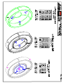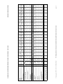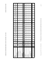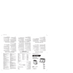
1
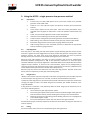
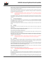
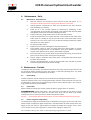
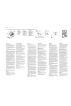
HF225 OPERATOR’S MANUAL DIXON INDUSTRIES PTY LTD ABN 89 008 171 855 17 Frederick Road, Royal Park, South Australia, 5014.Tel: +61 8 8240 1555. Fax: +61 8 8240 5588 Email: [email protected], HF225 manual hydraulic butt welder Simply Better. 1. Safety considerations ...............................................................................................................................3 2. Machine Description.................................................................................................................................4 2.1. General Specification ...........................................................................................................................4 2.2. Hydraulic System .................................................................................................................................4 2.3. Heater Plate .........................................................................................................................................5 2.4. Facer ....................................................................................................................................................5 2.5. Reducing Liners ....................................................................................................................................5 2.6. Fittings Attachment .............................................................................................................................5 2.7. Accessory Cases ...................................................................................................................................5 2.8. High Pressure Welding .........................................................................................................................5 3. Using the HF225 – single pressure low pressure method ........................................................................6 3.1. Preparation ..........................................................................................................................................6 3.2. Pipe Alignment ....................................................................................................................................6 3.3. Drag Pressure.......................................................................................................................................6 3.4. Facing ...................................................................................................................................................6 3.5. Re-Check Pipe Alignment .....................................................................................................................7 3.6. Bead Up ...............................................................................................................................................7 3.7. Heat Soak .............................................................................................................................................7 3.8. Fusion Cycle .........................................................................................................................................7 3.9. Weld Quality Check..............................................................................................................................8 4. 4.1. 5. Maintenance - Daily ..................................................................................................................................9 Maintenance - Daily Check List ............................................................................................................9 Maintenance - Periodic.............................................................................................................................9 5.1. General/Drag .......................................................................................................................................9 5.2. Heater Plate .........................................................................................................................................9 5.3. Heater Temperature Adjustment ........................................................................................................9 5.4. Temperature Calibration ...................................................................................................................10 5.5. Heater Non-Stick Cloth Replacement ................................................................................................10 5.6. Temperature Controller Failure .........................................................................................................10 5.7. Electrical safety testing heater plate .................................................................................................10 5.8. Element Pad Failure ...........................................................................................................................10 5.9. Hydraulic Operating Pressure ............................................................................................................11 5.10. Pressure Gauge Calibration ...............................................................................................................11 5.11. Hydraulic Bleeding Method ...............................................................................................................11 5.12. Facer Drive .........................................................................................................................................12 5.13. Cutter Blade Sharpening ....................................................................................................................12 6. Notes About Heater Plates And Temperature ........................................................................................13 6.1. PE Welding Temperatures .................................................................................................................13 6.2. Heater Plate Temperature .................................................................................................................13 6.3. Measuring Surface Temperature .......................................................................................................13 7. Butt Welding Guidelines .........................................................................................................................14 8. Weld failure trouble shooting.................................................................................................................14 9. Warranty.................................................................................................................................................15 10. Machine Assembly Drawings .............................................................................................................16 11. Butt Welding Tables (single pressure, low pressure) .........................................................................17 FUSIONMASTER® and DIXON® are registered trademarks of Dixon Industries Pty. Ltd. ©August 2002 Revised August 2013 Page 2 HF225 manual hydraulic butt welder Simply Better. 1. Safety considerations This machine should only be used by an operator fully trained in its use. Read these operating instructions carefully. Learn the operation, limitations and potential hazards of using your butt fusion machine. Avoid Dangerous Environments The equipment is not explosion proof. Never carry out butt fusion in a gaseous or combustible atmosphere. Electrical safety Use only a qualified electrician to carry out electrical maintenance work. Connect electrical components only to a voltage source that corresponds to that marked on the components. Do not operate the electrical equipment in damp or wet locations. Prevent electric shock by correctly grounding electrical components. The green (or green/yellow) conductor in the electric cable is the grounding wire and should never be connected to a live terminal. The use of earth leakage protection with portable electric tools is essential and must be provided by the user. Heater The heater operates at over 200°C and contact can cause serious burns. Always wear gloves when handling the hot plate. The heater is supplied with a short extension cord that has a high melting point outer sheath. This will delay, but will not prevent, the inevitable life threatening situation which could occur if the cord is allowed to contact the hot plate and melt through. Never use a standard appliance cord with low melting point PVC sheath. Standing the hot plate so that the temperature controller handle is not vertically above the hot plate will direct the cord away from the hot surface, and keep the controller relatively cool. Facer The facing machine is powerful and the cutting blades are sharp. To prevent injury the facer should only be operated when it is securely located in the pipe cutting position. The nature of the machine and welding process makes it impractical to guard the operational area. Do not attempt to remove shavings from the cutting area while the facer is running. Remove loose clothing or jewelry to prevent these items being dragged into moving parts. Hydraulic Pressure A sudden hydraulic oil leak can cause serious injury or even death if the pressure is high enough. Do not search for oil leaks with the fingers because a fine jet of pressurised oil could penetrate the skin causing serious injury. Use a piece of cardboard to test for leaks under pressure. Avoid spraying oil into eyes when bleeding air from the system by wearing safety glasses and keeping the face clear of the area. Keep fingers and limbs well clear of moving clamps, facer or heater to avoid crush injuries. Maintain Equipment Carefully The machine has moving parts and/or parts that may deteriorate with age and require maintenance. Regular inspection is recommended. For best results keep all machine components clean and properly maintained. Always disconnect the power when adjusting, servicing or changing accessories. Repair or replace damaged electric cables. Transporting The Machine Dixon equipment mounted on wheels is not designed for on-road towing. Any attempt to do so could result in machine damage and/or personal injury. Transportation should be by truck or similar, with the machine well secured. Do not allow the heater plate to contact the facer. FUSIONMASTER® and DIXON® are registered trademarks of Dixon Industries Pty. Ltd. ©August 2002 Revised August 2013 Page 3 HF225 manual hydraulic butt welder Simply Better. 2. Machine Description The FUSIONMASTER® HF225 is designed for “single pressure – low pressure” butt welding of pipe from 225mm down to 63mm. It is ideally suited to joining PE pipe to pipe in the field. The HF225 machine strength is derived from the hard chromed, high strength steel guide shafts, rigid sub frame and high strength cast aluminium alloy clamps. Mild steel machine components are zinc plated for maximum corrosion protection. Two solid rubber wheels and a basic machine weight of only 40kg allows easy mobility. The two fixed and two moving clamps have three segments to help reduce alignment problems caused by excessive pipe ovality. 2.1. General Specification Machine dimensions Main clamp bore 225 mm Length overall 860 mm Width overall 410 mm Height overall (wheels attached) 460 mm Component Weights Butt machine 40kg Heater plate 3.5kg Facer 11kg Fittings chuck 4.4kg Heater/Facer stand 5.2kg Reducing liner sets 3kg (min.) to 6.4kg (max.) Carry case containing heater, facer, liners 44kg Liner carry case (loaded) 45kg Shipping crate (loaded) 160 kg Hydraulic Specifications Cylinder area for weld calculation 753 mm² Hand pump, single acting 2.2. Relief valve setting 7,500kPa Pressure gauge 0 - 8,000kPa System oil capacity 0.75 litre Recommended hydraulic oil Any brand with viscosity ISO 46 Heater plate 1400W, 240V, single phase Minimum genset for field operation. 2.5kva, 240V, single phase Recommended grease for facer drive Shell Alvania EP/LF2 Hydraulic System The HF225 has a hand operated single acting hydraulic pump that applies pressure to a single hydraulic cylinder that transports the moving clamp carriage. Carriage motion direction is changed by a directional control valve located on the pump body. A needle valve is fitted between the pump and ram to lock off pressure during the fusion and cooling cycles. A direct pressure gauge indicates heating and joining pressures. FUSIONMASTER® and DIXON® are registered trademarks of Dixon Industries Pty. Ltd. ©August 2002 Revised August 2013 Page 4 HF225 manual hydraulic butt welder Simply Better. The maximum machine pressure is factory set by adjusting a pressure relief valve located in the pump. 2.3. Heater Plate The 1400W, 240V, single phase aluminium heater plate has a cast in circular element to ensure uniform heat distribution across the 240mm effective heating diameter. Plate temperature is regulated by an electronic controller sealed inside the heater handle. LED’s indicate when power is connected to the electric element. A dial thermometer indicates internal plate temperature. (Refer section on heater technology.) It takes less than 15 minutes to heat up to working temperature. Replaceable non-stick cloths are fitted to the heater surfaces to eliminate hot plastic adhesion. They are secured by snap rings enabling quick and easy field repair if the surface is damaged. The detachable 1.8m electric cord has a high melting point outer sheath for protection against short periods of accidental contact with the heater. When not in use, the heater plate is stored in a protective floor stand it shares with the facer. 2.4. Facer The lightweight electric powered facing head is self aligning and will always produce parallel pipe joint faces. Operating the variable speed motor at low speed will provide adequate torque and speed to process small or large diameter pipes quickly. There is one blade on each cutting face that will cut pipe from 225mm OD, to 45mm inside diameter. 2.5. Reducing Liners Each reducing liner set consists of 2 plain rings and 2 narrow rings. Each ring is made up of 3 segments. When welding pipe to pipe the plain rings are usually mounted in the inner two clamps, with the narrow rings in the two outer clamps. The narrow rings are for clamping short leg moulded fittings and must be placed in the inner clamps when welding elbows. The wide liners for 63mm, 75mm and 90mm nest inside 110mm wide liners. All the narrow liner sizes fit directly into the main 225mm clamp. 225-110mm plain liner (1 ring) Reducing liners can be manufactured to suit any pipe size from 200mm to 63mm, in either metric or imperial dimensions. Note: 2.6. The HF225 is not able to hold 225mm short leg moulded elbows or most short leg moulded Tees. Such fittings should be purchased with long leg lengths to enable the Tee or elbow section to protrude beyond the end clamp. 225-110mm narrow liner (1 ring) Fittings Attachment The fittings attachment tool is used when butt welding stub flanges or shouldered end fittings to pipe. It is usually held in the inner 225mm main clamp on the hydraulic cylinder side. The tool centrally locates flanges or shouldered ends quickly and accurately. It will securely hold the fitting either by the outside or inside diameter depending on the fitting size. 2.7. Accessory Cases A steel accessory case provides storage for the heater, the facer, the heater floor stand, and up to three sets of reducing liners. Up to five additional liner sets may be stored in a separate steel carry case. 2.8. High Pressure Welding The EHF225 is not designed for high pressure welding. However the high pressure method may be used providing the combined welding + drag pressure for a particular job falls within the range of the fitted pressure gauge. FUSIONMASTER® and DIXON® are registered trademarks of Dixon Industries Pty. Ltd. ©August 2002 Revised August 2013 Page 5 HF225 manual hydraulic butt welder Simply Better. 3. Using the HF225 – single pressure low pressure method 3.1. Preparation 1. 2. 3. 4. 5. 6. 7. 8. 9. 3.2. Connect only to a 240v, 50Hz power source. Ensure the output of any portable generator used is 240v ±20v. Check for air in the hydraulic system and bleed if necessary (see maintenance section). Clean and/or replace the non-stick cloths. Clean the heater plate before every weld with clean dry paper or cotton cloth - never use synthetic materials that may melt. Check, and if necessary adjust the heater surface temperature. Install the correct reducing liners for the pipe to be welded. Check the facer cutting action (the shaving thickness should be 0.30-0.40mm). Before facing, clean inside and outside of each pipe end, and the cutter blades. Record the drag pressure from the pressure gauge before every weld. Add the drag pressure to the calculated pressure to determine the appropriate bead up and fusion gauge pressures. Pipe Alignment Place the pipes in the clamp jaws with about 25mm of pipe extending past the clamps into the weld zone. Tighten the clamp toggle bolts securely to prevent the pipe from moving when under hydraulic pressure. The outer ends of the pipe should be supported such that any external bending loads on the machine are eliminated and drag pressure is minimised Move the pipe ends together until they are almost touching, then check for misalignment (maximum allowable misalignment is 10% of wall thickness). Tolerances on small bore pipes should be sufficient to permit pipe alignment in the HF225 without much adjustment of the three segment clamps. However, in severe out of round situations, adjust out any misalignment by loosening the clamps and rotating the pipes, and/or using packers as necessary. (Adjustment will not be possible if the pipe ends are in contact and under pressure.) Move the pipe end clear of the weld zone and record the drag pressure. Add this value to the fusion pressure required to join the pipe (refer welding table). 3.3. Drag Pressure "DRAG" is the amount of pressure required to overcome carriage friction plus the effort required to move the pipe. As drag pressure is a variable, it must be measured before every weld. To determine the drag pressure, operate the pump handle and observe the pressure at which the carriage just begins to move. The HF225 drag pressure without pipe loaded should be in the range 200-500kPa. If drag pressure is excessive it may adversely affect the weld. Drag may be reduced by one or more of the following actions: 1. 2. Use a low friction pipe support/roller system. Ensure the pipe support/roller system maintains the whole length of the pipe level with the machine base to prevent bending forces acting on the machine frame. 3. Minimise the amount of pipe being pulled. Welding machines are not designed to pull multiple lengths of pipe. 4. Ensure the heater/facer rest bar does not obstruct carriage movement All of these techniques are always important, but become critical when working near the limits of machine capacity. 3.4. Facing Ensure the heater plate rest bars are retracted during the facing operation. FUSIONMASTER® and DIXON® are registered trademarks of Dixon Industries Pty. Ltd. ©August 2002 Revised August 2013 Page 6 HF225 manual hydraulic butt welder Simply Better. Move the pipe ends apart and place the facing machine between the pipe faces. Ensure the facer body is securely hooked on to both guide shafts as this will ensure the facer sits square to the frame and parallel with the clamps. Start the facer rotating. Move the pipe ends into contact with the facer and apply the minimum pressure necessary to achieve cutting until a continuous shaving of plastic is simultaneously produced from both sides of the facer. Caution: To maximise drill and facer drive life, operate the drill at low speed (for maximum torque), and do not apply excessive carriage pressure – e.g. never exceed 1,000 kPa more than drag. On completion of facing, reverse the pipe carriage away from the facer then stop facer rotation. This prevents a step being produced in the faced ends. Raise the facer up and fully out of the machine. 3.5. Re-Check Pipe Alignment Clear away all plastic cuttings without contaminating the pipe ends. Do not touch the cut surface or re-clean it. Move the pipe ends together and re-check pipe alignment (maximum allowable misalignment is 10% of wall thickness). Always re-face the pipe ends if it becomes necessary to rotate the pipe in the clamps after initial facing. 3.6. Bead Up Extend the heater rest bars through the left clamp into the weld zone ready to support the heater plate. Check the heater plate temperature before commencing each joint in case there has been any failure of the power supply or temperature controller. Place the heater plate between the pipe faces. Move the carriage to bring the pipe faces into contact with the heater plate. Increase pressure to the predetermined “bead-up” pressure. Maintain pressure until an initial bead has formed completely around the pipe circumference on both sides of the heater plate. The bead up time is variable, and is influenced by weather conditions and pipe dimensions. Caution: 3.7. Ensure the heater handle is NOT standing vertically above the plate or dangerous overheating may occur. Do not allow the electric cord to rest on the hot plate. Heat Soak After bead up, reduce the pressure down to the drag pressure to maintain a slight positive pressure between the pipe and the heater for the heat soak period. Failing to reduce pressure forces hot plastic out of the joint zone and could lead to a weld failure. On completion of heat soak time, reverse the carriage direction to “crack” the heater plate away from the melted pipe, then move the heater plate out of the weld zone as quickly as possible. (Refer to parameters table for allowable changeover time). The unique non-stick cloths allow a "peeling off" action as the pipe is cracked away, minimising adhesion of the melted pipe to the heater. Remove the heater plate and replace it in the floor stand. Caution: 3.8. Do not allow the heater plate to slide across the pipe ends and distort the melted surface. Do not contaminate the melted surface in any way. Fusion Cycle Bring the melted pipe faces into contact with each other immediately to minimise heat loss from the weld zone. Smoothly build up to the required fusion pressure to avoid squeezing out too much hot plastic. Shrinkage will occur as the weld cools allowing the pressure to fall. Voids may also form in the weld zone. It is essential to operate the hand pump to maintain pressure until shrinkage ceases, FUSIONMASTER® and DIXON® are registered trademarks of Dixon Industries Pty. Ltd. ©August 2002 Revised August 2013 Page 7 HF225 manual hydraulic butt welder Simply Better. which could take 20 minutes or more for large pipes. Once the rate of pressure loss has diminished, close the lock off valve to maintain the hydraulic pressure at a sufficient level until the cooling cycle is completed. Maintain the pipe under pressure in the clamps until the weld/cooling time is complete. 3.9. Weld Quality Check Inspect the uniformity of the bead size inside and out, top and bottom of the pipe. It is advisable to monitor and record times, temperatures and pressures at each phase of every joint for future reference. (See section on trouble-shooting weld failures.) FUSIONMASTER® and DIXON® are registered trademarks of Dixon Industries Pty. Ltd. ©August 2002 Revised August 2013 Page 8 HF225 manual hydraulic butt welder Simply Better. 4. Maintenance - Daily 4.1. Maintenance - Daily Check List 1. 2. 3. 4. 5. 6. 7. 8. 9. 10. 11. Keep the machine and accessories clean and free of dust and grease. Do not lubricate any HF225 components except for the facer drive (see later). Inspect hydraulic components for leaks from connections and seals. Overhaul seals and fittings as necessary. Check for air in the carriage cylinder (as evidenced by shuddering, and/or “springing back” of the cylinder). Air trapped in the hydraulics will adversely affect weld quality and must be removed by bleeding (see later). Check the pressure gauge needle returns to zero and does not stick. Check the temperature of a number of points on the surface of both sides of the heater plate. The reading at any point on either side of the heater plate surface should not be more than ±10°C from the desired welding temperature. (Refer later section on heater plates.) Do electrical safety checks. Replace non-stick cloths if damaged in way of the weld area. Facing blades should be sharp and have defect free cutting edges to provide continuous shaving thickness of 0.30-0.40mm. Shim worn blades if necessary; sharpen cutter blades if blunt; replace cutter blades if chipped. Ensure the facer drill is securely fixed into the facer body casting, if not the drive gears may not mesh properly causing extensive damage. Feel for “sloppy” movement of the cutter plates. This indicates the need to adjust the facer drive internally. If using a portable generator, ensure its output is 240v ± 20v and 50hz, to protect electronic equipment from permanent damage. 5. Maintenance - Periodic In addition to the daily checks, more detailed inspections of the key machine components should be carried out before commencing each new project, or after 250 operating hours. Any faults found should be corrected as described in this section. 5.1. General/Drag Check the hydraulic cylinder shafts for cuts or dents likely to damage the hydraulic seals. Check the machine frame, main carriage guide shafts, hydraulic shafts and heater rest bars are not damaged or bent such that excessive drag pressure results. Without pipe in the machine, drag pressure should not exceed 500kPa. 5.2. Heater Plate Heater surfaces should be flat, smooth and free of dents or gouges. Dress as necessary. FUSIONMASTER® heater plates have a vent machined in the edge of the casting to allow entrapped air to escape from under the non-stick cloth. Clean out any build up of foreign material from the air vent to prevent any adverse temperature effect. Caution: 5.3. Ensure heater plate non-stick surfaces are protected from damage during transport. Heater Temperature Adjustment The temperature setting of the HF225 heater is adjusted by turning the screw in the end of the heater handle, clockwise for higher temperature, and anticlockwise for lower temperature. One degree of turn will result in approximately one degree of temperature change. Always allow several minutes for the plate temperature to stabilise after making any adjustment. The controller is factory set to 220°C. It has an operating range of 180°C to 260°C. FUSIONMASTER® and DIXON® are registered trademarks of Dixon Industries Pty. Ltd. ©August 2002 Revised August 2013 Page 9 HF225 manual hydraulic butt welder Simply Better. 5.4. Temperature Calibration The thermometer in the heater plate indicates the internal plate temperature not the surface temperature, although the difference will not be great. It is essential to check and record the surface temperature of the heater plate before every weld. This is best measured with either a contact pyrometer or a non contact infrared pyrometer. The outer circumference of the heater should not be measured as this is too far from the weld area. The pyrometer used to measure surface temperature will itself require calibration to a procedure as recommended by the pyrometer manufacturer. Caution: 5.5. Be aware that an insulating air gap can form between the Teflon cloth and the hot plate. Always ensure the cloth is forced into contact with the hot metal surface when using an infrared or non contact pyrometer or a false reading is likely to occur. Never use an infrared pyrometer on a shiny surface as a false reading will occur. Heater Non-Stick Cloth Replacement The non-stick cloths should be replaced if they are torn, contaminated, or badly discoloured (due to overheating) or lose their non-stick ability. Use the following procedure. 1. 2. 3. 5.6. Temperature Controller Failure 1. 2. 5.7. Use a screw driver to lever the snap rings out of their securing grooves. This takes very little force. Do not attempt to remove the snap rings if the plate temperature is more than 40°C because they will not release. With the plate flat, place a new cloth into position and reposition the snap ring over the cloth. Push the snap ring into the groove around an arc of the plate. Hold in position with one hand. With the free hand, use a piece of wood or plastic to force the snap ring completely into its groove. (This may take several attempts until some experience is developed.) Never use metallic objects to force the snap rings back into position as this may result in accidental damage to the cloth. When power is connected, one LED glows amber. When the electric element is drawing power the other LED glows red. Either of the LEDs flashing on-off indicates the temperature controller has failed and must be replaced. If neither LED glows when power is connected, first test the power supply and the power cord to ensure those items are not at fault. If not faulty, next test the element pad before replacing the temperature controller. Electrical safety testing heater plate Use an appliance tester capable of performing a Class 1 250V Run Test to verify the functionality of FUSIONMASTER® model MV70, SV70, LF110, HF225, EHF225 heater plates. These devices cannot be safety tested either as an earthed appliance or as a double insulated appliance because the temperature controller Is fitted with surge protection (i.e. metal oxide varistor), and uses solid state switching that only functions when power is applied. 5.8. Element Pad Failure Caution: This job must be performed by a qualified electrician. 1. Disconnect the power supply. 2. (Refer to heater plate drawing.) Remove the screws securing the temperature controller handle to the heater bracket, and the screws securing the bracket to the heater plate. 3. Remove the bracket and gasket from the heater plate to expose the temperature sensor probe. (If the gasket is broken by this action it should be replaced.) 4. Withdraw the sensor probe with long nose pliers, pulling on the metal case, not the fine lead wires. 5. Disconnect the quick connect leads from the element ends and unscrew the earth connection and measure the resistance across the two ends of the element FUSIONMASTER® and DIXON® are registered trademarks of Dixon Industries Pty. Ltd. ©August 2002 Revised August 2013 Page 10 HF225 manual hydraulic butt welder Simply Better. 6. 7. 8. 5.9. (should be 40 ohms ±10%). If there is a short circuit, the element pad must be replaced. If the element, leads and connectors are OK, the controller will be faulty and must be replaced. Before re-fitting the controller, sparingly coat the sensor probe with some silicon heat sink compound to increase thermal sensitivity, then carefully insert the probe into the probe hole. Reassemble the handle and bracket to the heater plate and tighten screws securely. Reconnect the power cord and switch on. Both LEDs should glow immediately. Allow 20 minutes for the heater to reach temperature and to stabilise before making any adjustments or measuring temperature. Hydraulic Operating Pressure The operating pressure of the HF225 is limited to 7,500kPa by a relief valve on the side of the pump. Should it be necessary to adjust the relief pressure contact the manufacturer for advice. Care should be taken if increasing the pressure above this setting as the pressure gauge may be damaged. (Older models were fitted with a 0-6000kPa gauge with operating pressure limited to 5,500kPa.) 5.10. Pressure Gauge Calibration Pressure gauges are easily damaged and may lose their accuracy. Periodically either 1. 2. 5.11. Remove the pressure gauge and check it against a known standard test gauge, or Replace the pressure gauge with a certified gauge from time to time. Hydraulic Bleeding Method The presence of air in the system could result from loose hydraulic fittings, damaged hydraulic cylinder shaft or seals. These should all be inspected and repaired before bleeding the system. The following method is recommended for recharging with oil (use ISO 46 viscosity) 1. 2. 3. 4. 5. 6. 7. 8. Check there are no loose hydraulic fittings. The hydraulic system contains approximately 750ml of oil in total. With the machine standing in its normal position, remove the filler/breather cap from the oil reservoir, insert a filling funnel and add oil to the reservoir. The reservoir oil level should be kept about 25mm below the filler/breather cap. Operate the pump and directional valve alternately such that the cylinder moves slowly no more than 50mm in either direction. Top up the reservoir as required, especially if motion stops while pumping. Repeat this action several times, increasing the distance moved by the cylinder a few millimetres each time as more oil is transferred into the cylinder. If oil is ejected from the filler/breather cap during this operation reduce the distance and/or speed of travel. As the amount of air being forced from the system reduces, rotate the machine along its longitudinal axis so that the cylinder piping entry points face vertically up which allows trapped air to rise and escape. Do not omit this step or air will remain in the system. Continue pumping and move the cylinder to the fully open position, then back to the fully closed position. Repeat this cycle in each direction until any operation of the pump handle and the resultant motion of the carriage, is immediate and exactly in sequence. There should also be no clamp spring back at the end of the cylinder stroke (either end) on changing the directional control valve. At this point all air should be fully expelled from the system. Top up the reservoir when the cylinder shaft is retracted such that the oil level is about 25mm below the filler/breather cap. FUSIONMASTER® and DIXON® are registered trademarks of Dixon Industries Pty. Ltd. ©August 2002 Revised August 2013 Page 11 HF225 manual hydraulic butt welder Simply Better. 5.12. Facer Drive Refer to Facer drawing. 1. 2. 3. 4. 5. 5.13. Access the facer drive assembly by removing the securing screw from the facer plate and removing the plate. Inspect the worm and worm wheel assembly for wear. If the worm, or worm wheel, or worm shaft or dog coupling is excessively worn or broken, the complete worm drive assembly must be replaced as a matching assembly. Inspect the worm shaft needle thrust bearing for damage and replace if necessary. Otherwise, clean out and re-grease sparingly with a high pressure grease e.g. Shell Alvania EP2. Do not use molybdenum disulphide, graphite grease or similar as these may run and cause welding contamination. Replace felt dust seals as required. Cutter Blade Sharpening If chipped or damaged, the blades should be replaced. If blunt, the high grade tool steel blades may be sharpened with a die grinder. Shim the cutter blades if they are sharp, but shavings are too thin. FUSIONMASTER® and DIXON® are registered trademarks of Dixon Industries Pty. Ltd. ©August 2002 Revised August 2013 Page 12 HF225 manual hydraulic butt welder Simply Better. 6. Notes About Heater Plates And Temperature 6.1. PE Welding Temperatures Polyethylene pipe is weldable at temperatures ranging from 180°C to 260°C. However butt fusion parameters typically specify 220 ±15°C which is the required surface temperature of the heater plate. Temperatures greater than 240°C when coupled with long heat soak times may result in diminution of the anti-oxidants in the pipe. Cold joints will result if the weld temperature is too low, or the heat soak time is too short, or the time between removal of the heater and butting the pipes together is too long. Caution: 6.2. Either situation may lead to premature joint failure. Heater Plate Temperature Heater plate temperature displays generally indicate the internal heater temperature. Actual surface temperature may vary from the display, and will also fluctuate, for the following reasons. 1. 2. 3. 4. 6.3. Measuring Surface Temperature 1. Note: It is not physically possible for heater surface temperatures to vary significantly from one point to another. If such a variation is observed, it is most likely to result from using an incorrect temperature measuring technique. The rate of heat loss from the heater surface depends on the design of the heater plate and temperature controller. The surface temperature could be significantly different to the thermometer indication. This variation will be greatest on cold, windy days. Always use a shelter when welding in these conditions. As power input cycles on and off the temperature will be highest just after the power cycles off and lowest just as it cycles back on. The temperature is unlikely to be exactly the same at every point on the heater surface due to manufacturing tolerances. As heat is transferred into the pipe during heat soak, the heater temperature initially falls but eventually returns to the set point. 2. 3. 4. 5. 6. Always wait 5 minutes after the heater has first reached set temperature for the temperature to stabilize before recording measurements. Take readings at several points (at 3, 6, 9, 12 o’clock) on both sides of the heater, at the diameter of the pipe being welded. FUSIONMASTER heater plates are fitted with non-stick replaceable cloth. It is essential to use a contact probe to force the cloth into intimate contact with the plate. (Incorrect readings will result when the cloth system traps an insulating air layer between the cloth and the heater surface.) If a contact probe is used it should be held in position for several seconds before the reading is taken. If an infra red pyrometer is used incorrect reading are likely to result unless: • the emissivity is set at 0.95 for use on the non-stick cloth; • the device is held square to the surface being measured; • the non-stick cloth is forced into intimate contact with the heater plate (see suggestion below). Never use an infra-red pyrometer to take a reading from a shiny aluminium surface (such as a FUSIONMASTER heater without cloths, or the outer rim of a heater plate) or an error will result. Suggestion Use a "spot control adapter" fitted to an Infra-red pyrometer for consistently accurate measurements. When pressed squarely against the heater surface the infra-red beam is correctly focused every time, and intimate contact between the heater plate and non-stick cloth is assured. FUSIONMASTER® and DIXON® are registered trademarks of Dixon Industries Pty. Ltd. ©August 2002 Revised August 2013 Page 13 HF225 manual hydraulic butt welder Simply Better. 7. Butt Welding Guidelines It is recommended that the following guidelines be downloaded from Plastics Industry Pipe Association of Australia Ltd web site (www.pipa.com.au) 1. POP003 Butt Fusion Jointing of PE Pipes and Fittings - Recommended Parameters. 2. TP003 Specifying Butt Welding of Polyethylene Pipe Systems. FUSIONMASTER® welders are designed for the “single pressure – low pressure” fusion method described in POP003. The welding tables appended to the HF225 operating manual are based on POP003-SP-LP. Operators should take care to determine the compatibility of materials for butt welding and only attempt to weld pipes and fittings made of the same polymer, eg PE to PE, PP to PP, PVDF to PVDF, etc. The joint area must always be protected from adverse weather conditions, eg strong winds, excessive cold or heat, or rain, which could lead to the pipe wall developing non-uniformly heated zones and consequent failure issues. The weld zone should be free of bending stress, free of notches or similar damage, and be free of contamination. 8. Weld failure trouble shooting (Bead shapes are exaggerated for effect.) Uniform bead correct welding. NB the external bead is always more uniform than the internal bead. Crack down centre of bead. "Cold weld" signified by clean break through the middle of the weld with a smooth appearance. Could be due to insufficient heat soak time or temperature, or changeover time too long, or excessive soak pressure, or insufficient fusion pressure, or no allowance for drag pressure, or drag pressure too great eg due to pulling pipe up a gradient. Misalignment - maximum allowable 10% of wall thickness. Care should also be taken to ensure pipes or fittings being joined have the same diameter and wall thickness or the probability of weld failure is significantly increased. Insufficient bead roll over. Could be due to insufficient heat soak time or temperature, or changeover time too long, or insufficient fusion pressure, or no allowance for drag pressure, Unequal bead size. Look for temperature gradients e.g. pipe surface in the hot sun vs pipe in the shade, or heater plate hot spots. Look for unequal application of pressure. If unequal uniformly around the whole circumference, look for physical difference in materials being joined eg melt flow index. FUSIONMASTER® and DIXON® are registered trademarks of Dixon Industries Pty. Ltd. ©August 2002 Revised August 2013 Page 14 HF225 manual hydraulic butt welder Simply Better. 9. Warranty FUSIONMASTER Butt Fusion Equipment 1. 2. 3. 4. 5. 6. 7. Subject to the terms below, Dixon Industries Pty Ltd (“The Company”) warrants to repair or replace at its option ex-works Adelaide any product manufactured or repaired by it within 2 years from the date of shipment which are found to be defective due to either faulty workmanship or use of faulty materials, provided that such defective product is returned to the Company’s works at the customer’s expense, unless otherwise agreed. This warranty is limited solely to products manufactured or repaired by the Company. Products not manufactured by the Company (such as pumps, gauges, motors, switches, etc.) are not covered by this warranty. In relation to a repair, this warranty is limited to the Company’s cost of parts and labour to remedy a defective repair. This warranty does not apply to any product that has been damaged by accident, misuse, neglect, use of an electrical power supply that is incompatible with the design specifications of the product or repair or alteration of the product by anyone other than the Company. A warranty claim must be made to the Company in writing within 14 days of the first occurrence of the event or condition on which the claim is based. The claim must include proof of purchase and a detailed statement of the manner in which the product has been used and the event or condition occurred. The Company’s decision to admit or refuse any warranty claim shall be binding. Replacement parts provided to the customer before the right to a warranty claim is accepted by the Company will be invoiced at the full cost of the parts, including applicable taxes and freight charges. If a warranty claim is accepted, the cost of any replacement parts covered by the warranty claim which have been so invoiced will be credited to the customer. All costs of returning product to the customer shall be paid by the customer. Other than provided in this warranty, the Company excludes any other responsibility or liability whatever to the maximum extent permitted by law including liability for breach of contract, negligence or incidental, consequential, indirect or special damages including without limitation, interruption to use of the product or any other plant or equipment. Disclaimer As the conditions of use of welding equipment are outside the control of Dixon Industries, no warranties are expressed or implied and no liability is assumed in connection with the use of butt welding equipment or the butt welding guidelines or parameters. The manufacturer reserves the right to vary specifications without notice. FUSIONMASTER® and DIXON® are registered trademarks of Dixon Industries Pty. Ltd. ©August 2002 Revised August 2013 Page 15 UNCONTROLLED DOCUMENT 4 16 22 23 18 1 5 13 12 13 9 8 20 11 19 15 14 7 Facer Worm Drice Assembly, Part No. BF200203 10 6 17 26 21 23 2 24 25 not to scale Update: 6/11/12 Drawn: SR Scale: BF225231 BF000239 BF225240_2 BF225208 BF225201_2 5 4 3 2 1 A.B.N. 89 008 171 855 Part No. BF200224 6 Item BF200221 QTY 1 1 1 1 3 1 1 1 1 1 1 1 2 1 3 1 1 1 2 2 1 1 6 1 1 1 www.dixonind.com.au Copyright ©. No part of this drawing may be reproduced in whole or in part without the written permission of Dixon Industries Pty. Ltd. Part Name Facer Body Dog Coupling DRP20ET Drill suit 225 Facer Set Screw 5/16"xs 5/15" Nylon Bush Dog Coupling Fixed Silver Steel Shaft Worm BF200222 7 Spring Pin 3/16"x 1" Acetal Spacer BF000222 BF200210 11 Thrust Bearing Spring Pin 1/8" x 3/4" BF000176 12 Thrust Washer Worm Wheel Spring Pin 3/16"x 1 1/4" Cutter Plate (bored) Cutter Plate ( tapped) SHCS 3/8"x 2" Thrust Ring - pair Felt Seal - pair Cutter Blade ( tapped) Cutter Blade (bored) Blade Screws Facer Handle Hex Nut M16 SHCS 1/4"x 3/4" BF000213 BF000207 13 Worm & 10 Coupling Assembly 9 Part No. BF200220 8 BF200223 14 BF200208 17 BF000337 BF000267 18 15 BF200207 19 BF200202 BF200205 20 16 BF200212T BF200212B 22 BF200218 24 BF000217 BF000166 25 23 BF000232 26 BF200212 21 Kit Part No. Cutter Blades & Screws, CAD File: U:\Inventor\HF225\225200\BF225200_4.idw OPERATORS MANUAL ONLY HF225 Fasser Assembly Drawing Name: 3 NOTE: PROTOOL DRP20ET & DRP20ET Coupling used after 17/01/2012 UNCONTROLLED DOCUMENT 17 15 15 17 16 19 20 21 35 22 23 37 36 25 24 26 18 12 14 13 34 11 10 9 8 33 32 not to scale Update: 11/05/2012 Drawn: SR Scale: BF200672 Directional Control Lever optional BF000091 Spring (Check Valve) 18 Steel Ball Steel Valve Hex Bolt M10 x 20 BF000147 BF000141 BF000333 9 8 7 6 5 1 QTY Part Name A.B.N. 89 008 171 855 Item Pump Body 1 www.dixonind.com.au Copyright ©. No part of this drawing may be reproduced in whole or in part without the written permission of Dixon Industries Pty. Ltd. 1 1 Tank Cover/Reservoir-mod. 2 1 Washer 3 1 2 Rubber Seal Hex Bolt M8 x 65 2 1 1 1 1 1 1 1 2 1 2 1 1 1 1 1 4 Part No. Spring Clip 10 Flat Washer M10 Reataining Screw 11 Aluminium Knob Directional Spool BF200671 12 13 Spring Pin Valve Screw 15 14 Washer 16 Copper Washer Check Valve 19 17 Spring (Check V. press.relief) Check Valve - pressure relief 21 20 Plug 22 1 1 Breather 23 1 1 1 Handle (modified) 26 1 Piston Hinge 27 2 24 HingePin - long 28 6 B/Up Washer Hinge Pin - short 29 1 1 25 Retaining Washer 30 O-Ring (BS242) 31 1 1 O-Ring (10x2) O-Ring (BS115) 1 Washer (BD021) 32 1 O-Ring (14x3) Washer (BD027) 1 Oil Seal/ Case Wiper 33 Seal Kit, 37 HF225 Pump P.No.:200650 36 supplied if 35 required 34 Note: All parts without part number are components of purchased pump CAD File: U:\Inventor\HF225\225600\BF200658.idw OPERATORS MANUAL ONLY HF225 Hydraulic Hand Pump modified Drawing Name: 5 3 4 2 31 1 6 7 30 28 27 29 29 t+3 t+3 P3 P2 T2 T3 T4 P3 P3 P3 T5 total bead up pressure soak pressure soak time heater out pressure up welding & cooling pressure + measured drag total welding & cooling pressure minimum welding & cooling time in the clamps cooling time out of clamps before rough handling T6 PE welding parameters POP003.6.1 SPLP.xls FUSIONMASTER225 +drag 170+/-20 0.4t + 2 0.1t + 4 (11±1)t drag +drag 170+/-20 P1 P3 bead up pressure 0.1t 220+/-15 + measured drag allowable axial misalignment mean heater surface temp minute minute kPa kPa kPa second second second kPa kPa kPa kPa mm °C 10 10 1128 5 5 80 drag 1128 0.7 220 7.3 PN4 33 225 12 12 1394 6 5 100 drag 1394 0.9 220 9.1 PN6.3 26 225 14 14 1728 7 5 125 drag 1728 1.1 220 11.4 PN8 PN6.3 21 225 17 17 2117 8 5 156 drag 2117 1.4 220 14.2 PN10 PN8 17 225 225 21 21 2576 9 6 193 drag 2576 1.8 220 17.5 PN12.5 PN10 13.6 25 25 3117 11 6 238 drag 3117 2.2 220 21.6 PN16 PN12.5 11 225 29 29 3725 13 7 291 drag 3725 2.6 220 26.5 PN20 PN16 9 225 35 35 4426 15 7 356 drag 4426 3.2 220 32.4 PN25 PN20 7.4 225 8 8 719 4 5 57 drag 719 0.5 220 5.2 PN4 PN3.2 41 200 10 10 906 5 5 73 drag 906 0.7 220 6.6 PN4 33 200 NB the drag pressure must be re-measured and added to the calculated weld pressure for each new joint. 5 5 317 3 4 22 drag 317 0.2 220 2.0 Parameter PN4 mean wall thickness mm PE100 t PN3.2 225 PE80 mm 41 D SDR nominal pipe od Parameters based on PIPA Guideline POP003: 6.1 Sept 2011, Single Pressure - Low Pressure. 11 11 1109 5 5 90 drag 1109 0.8 220 8.2 PN6.3 26 200 13 13 1367 6 5 112 drag 1367 1.0 220 10.2 PN8 PN6.3 21 200 16 16 1669 7 5 138 drag 1669 1.3 220 12.6 PN10 PN8 17 200 19 19 2029 8 6 171 drag 2029 1.6 220 15.5 PN12.5 PN10 13.6 200 22 22 2463 10 6 211 drag 2463 1.9 220 19.2 PN16 PN12.5 11 200 32 32 3492 14 7 316 drag 3492 2.9 220 28.8 PN25 PN20 7.4 200 appendix 1/5 27 27 2953 11 6 260 drag 2953 2.4 220 23.6 PN20 PN16 9 200 225 hydraulic cylinder area 753mm² t+3 t+3 P3 P2 T2 T3 T4 P3 P3 P3 T5 total bead up pressure soak pressure soak time heater out pressure up welding & cooling pressure + measured drag total welding & cooling pressure minimum welding & cooling time in the clamps cooling time out of clamps before rough handling T6 PE welding parameters POP003.6.1 SPLP.xls FUSIONMASTER225 +drag 170+/-20 0.4t + 2 0.1t + 4 (11±1)t drag +drag 170+/-20 P1 P3 bead up pressure 0.1t 220+/-15 + measured drag allowable axial misalignment mean heater surface temp minute minute kPa kPa kPa second second second kPa kPa kPa kPa mm °C 9 9 729 4 5 65 drag 729 0.6 220 5.9 PN4 33 180 10 10 895 5 5 80 drag 895 0.7 220 7.3 PN6.3 26 180 12 12 1104 6 5 100 drag 1104 0.9 220 9.1 PN8 PN6.3 21 180 14 14 1353 7 5 124 drag 1353 1.1 220 11.3 PN10 PN8 17 180 180 17 17 1654 8 5 155 drag 1654 1.4 220 14.1 PN12.5 PN10 13.6 20 20 1997 9 6 190 drag 1997 1.7 220 17.3 PN16 PN12.5 11 180 24 24 2388 10 6 233 drag 2388 2.1 220 21.2 PN20 PN16 9 180 29 29 2831 12 7 285 drag 2831 2.6 220 25.9 PN25 PN20 7.4 180 7 7 470 4 4 47 drag 470 0.4 220 4.3 PN4 PN3.2 41 160 8 8 571 4 5 57 drag 571 0.5 220 5.2 PN4 33 160 NB the drag pressure must be re-measured and added to the calculated weld pressure for each new joint. 8 8 585 4 4 52 drag 585 0.5 220 4.7 Parameter PN4 mean wall thickness mm PE100 t PN3.2 180 PE80 mm 41 D SDR nominal pipe od Parameters based on PIPA Guideline POP003: 6.1 Sept 2011, Single Pressure - Low Pressure. 10 10 719 5 5 73 drag 719 0.7 220 6.6 PN6.3 26 160 11 11 878 5 5 90 drag 878 0.8 220 8.2 PN8 PN6.3 21 160 13 13 1069 6 5 111 drag 1069 1.0 220 10.1 PN10 PN8 17 160 15 15 1303 7 5 137 drag 1303 1.2 220 12.5 PN12.5 PN10 13.6 160 18 18 1580 8 6 169 drag 1580 1.5 220 15.4 PN16 PN12.5 11 160 26 26 2239 11 6 254 drag 2239 2.3 220 23.1 PN25 PN20 7.4 160 appendix 2/5 22 22 1888 10 6 207 drag 1888 1.9 220 18.9 PN20 PN16 9 160 225 hydraulic cylinder area 753mm² t+3 t+3 P3 P2 T2 T3 T4 P3 P3 P3 T5 total bead up pressure soak pressure soak time heater out pressure up welding & cooling pressure + measured drag total welding & cooling pressure minimum welding & cooling time in the clamps cooling time out of clamps before rough handling T6 PE welding parameters POP003.6.1 SPLP.xls FUSIONMASTER225 +drag 170+/-20 0.4t + 2 0.1t + 4 (11±1)t drag +drag 170+/-20 P1 P3 bead up pressure 0.1t 220+/-15 + measured drag allowable axial misalignment mean heater surface temp minute minute kPa kPa kPa second second second kPa kPa kPa kPa mm °C 8 8 442 4 4 51 drag 442 0.5 220 4.6 PN4 33 140 9 9 548 4 5 63 drag 548 0.6 220 5.8 PN6.3 26 140 10 10 670 5 5 78 drag 670 0.7 220 7.1 PN8 PN6.3 21 140 12 12 819 6 5 97 drag 819 0.9 220 8.8 PN10 PN8 17 140 140 14 14 999 6 5 120 drag 999 1.1 220 10.9 PN12.5 PN10 13.6 16 16 1204 7 5 147 drag 1204 1.3 220 13.4 PN16 PN12.5 11 140 20 20 1450 9 6 182 drag 1450 1.7 220 16.6 PN20 PN16 9 140 23 23 1720 10 6 223 drag 1720 2.0 220 20.3 PN25 PN20 7.4 140 6 6 285 3 4 36 drag 285 0.3 220 3.3 PN4 PN3.2 41 125 7 7 356 4 4 46 drag 356 0.4 220 4.2 PN4 33 125 NB the drag pressure must be re-measured and added to the calculated weld pressure for each new joint. 7 7 363 4 4 41 drag 363 0.4 220 3.8 Parameter PN4 mean wall thickness mm PE100 t PN3.2 140 PE80 mm 41 D SDR nominal pipe od Parameters based on PIPA Guideline POP003: 6.1 Sept 2011, Single Pressure - Low Pressure. 8 8 434 4 5 56 drag 434 0.5 220 5.1 PN6.3 26 125 9 9 535 5 5 70 drag 535 0.6 220 6.4 PN8 PN6.3 21 125 11 11 653 5 5 86 drag 653 0.8 220 7.9 PN10 PN8 17 125 13 13 797 6 5 107 drag 797 1.0 220 9.8 PN12.5 PN10 13.6 125 15 15 966 7 5 133 drag 966 1.2 220 12.1 PN16 PN12.5 11 125 21 21 1370 9 6 199 drag 1370 1.8 220 18.1 PN25 PN20 7.4 125 appendix 3/5 18 18 1154 8 5 162 drag 1154 1.5 220 14.8 PN20 PN16 9 125 225 hydraulic cylinder area 753mm² t+3 t+3 P3 P2 T2 T3 T4 P3 P3 P3 T5 total bead up pressure soak pressure soak time heater out pressure up welding & cooling pressure + measured drag total welding & cooling pressure minimum welding & cooling time in the clamps cooling time out of clamps before rough handling T6 PE welding parameters POP003.6.1 SPLP.xls FUSIONMASTER225 +drag 170+/-20 0.4t + 2 0.1t + 4 (11±1)t drag +drag 170+/-20 P1 P3 bead up pressure 0.1t 220+/-15 + measured drag allowable axial misalignment mean heater surface temp Parameter minute minute kPa kPa kPa second second second kPa kPa kPa kPa mm °C 7 7 276 3 4 40 drag 276 0.4 220 3.7 PN4 33 110 8 8 344 4 4 51 drag 344 0.5 220 4.6 PN6.3 26 110 9 9 419 4 5 62 drag 419 0.6 220 5.7 PN8 PN6.3 21 110 10 10 512 5 5 77 drag 512 0.7 220 7.0 PN10 PN8 17 110 110 12 12 619 5 5 95 drag 619 0.9 220 8.6 PN12.5 PN10 13.6 14 14 748 6 5 117 drag 748 1.1 220 10.6 PN16 PN12.5 11 110 16 16 895 7 5 143 drag 895 1.3 220 13.0 PN20 PN16 9 110 19 19 1064 8 6 175 drag 1064 1.6 220 16.0 PN25 PN20 7.4 110 5 5 150 3 4 26 drag 150 0.2 220 2.4 PN4 PN3.2 41 90 6 6 186 3 4 33 drag 186 0.3 220 3.0 PN4 33 90 NB the drag pressure must be re-measured and added to the calculated weld pressure for each new joint. 6 6 221 3 4 32 drag 221 0.3 220 2.9 mean wall thickness mm PN4 t PN3.2 PE100 110 PE80 mm 41 D SDR nominal pipe od Parameters based on PIPA Guideline POP003: 6.1 Sept 2011, Single Pressure - Low Pressure. 7 7 230 4 4 41 drag 230 0.4 220 3.8 PN6.3 26 90 8 8 279 4 4 51 drag 279 0.5 220 4.6 PN8 PN6.3 21 90 9 9 344 4 5 63 drag 344 0.6 220 5.8 PN10 PN8 17 90 10 10 413 5 5 77 drag 413 0.7 220 7.0 PN12.5 PN10 13.6 90 12 12 502 5 5 96 drag 502 0.9 220 8.7 PN16 PN12.5 11 90 90 16 16 710 7 5 143 drag 710 1.3 220 13.0 PN25 PN20 7.4 appendix 4/5 14 14 602 6 5 118 drag 602 1.1 220 10.7 PN20 PN16 9 90 225 hydraulic cylinder area 753mm² t+3 t+3 P3 P2 T2 T3 T4 P3 P3 P3 T5 total bead up pressure soak pressure soak time heater out pressure up welding & cooling pressure + measured drag total welding & cooling pressure minimum welding & cooling time in the clamps cooling time out of clamps before rough handling T6 PE welding parameters POP003.6.1 SPLP.xls FUSIONMASTER225 +drag 170+/-20 0.4t + 2 0.1t + 4 (11±1)t drag +drag 170+/-20 P1 P3 bead up pressure 0.1t 220+/-15 + measured drag allowable axial misalignment mean heater surface temp Parameter minute minute kPa kPa kPa second second second kPa kPa kPa kPa mm °C 6 6 129 3 4 28 drag 129 0.3 220 2.5 PN4 33 75 6 6 159 3 4 34 drag 159 0.3 220 3.1 PN6.3 26 75 7 7 195 4 4 42 drag 195 0.4 220 3.9 PN8 PN6.3 21 75 8 8 239 4 4 53 drag 239 0.5 220 4.8 PN10 PN8 17 75 75 9 9 287 4 5 64 drag 287 0.6 220 5.9 PN12.5 PN10 13.6 75 10 10 347 5 5 79 drag 347 0.7 220 7.2 PN16 PN12.5 11 12 12 418 6 5 98 drag 418 0.9 220 8.9 PN20 PN16 9 75 75 14 14 496 6 5 120 drag 496 1.1 220 10.9 PN25 PN20 7.4 63 5 5 77 3 4 19 drag 77 0.2 220 1.8 PN4 PN3.2 41 63 5 5 93 3 4 24 drag 93 0.2 220 2.2 PN4 33 NB the drag pressure must be re-measured and added to the calculated weld pressure for each new joint. 5 5 107 3 4 23 drag 107 0.2 220 2.1 mean wall thickness mm PN4 t PN3.2 PE100 75 PE80 mm 41 D SDR nominal pipe od Parameters based on PIPA Guideline POP003: 6.1 Sept 2011, Single Pressure - Low Pressure. 63 6 6 112 3 4 29 drag 112 0.3 220 2.6 PN6.3 26 63 6 6 136 3 4 35 drag 136 0.3 220 3.2 PN8 PN6.3 21 7 7 170 4 4 45 drag 170 0.4 220 4.1 PN10 PN8 17 63 8 8 206 4 5 55 drag 206 0.5 220 5.0 PN12.5 PN10 13.6 63 9 9 248 4 5 68 drag 248 0.6 220 6.2 PN16 PN12.5 11 63 63 12 12 348 6 5 100 drag 348 0.9 220 9.1 PN25 PN20 7.4 appendix 5/5 11 11 297 5 5 83 drag 297 0.8 220 7.6 PN20 PN16 9 63 225 hydraulic cylinder area 753mm² DIXON INDUSTRIES PTY LTD ABN 89 008 171 855 17 Frederick Road, Royal Park South Australia, 5014. Tel: (08) 8240 1555 Fax: (08) 8240 5588