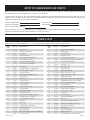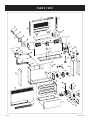
1
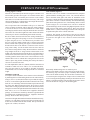
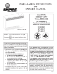
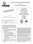
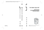
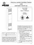
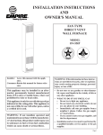
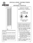
INSTALLATION INSTRUCTIONS
AND
OWNER'S MANUAL
FAN TYPE
Direct Vent
Wall Furnace
For Installation in
Manufactured (Mobile Home),
Modular or Residential Homes
Patent # 5.664.555
Model
DV-55E-5
Installer: Leave this manual with the appliance.
Consumer:Retain this manual for future reference.
WARNING: If the information in these instructions are not followed exactly, a fire or explosion
may result causing property damage, personal
injury or loss of life.
— Do not store or use gasoline or other flammable vapors and liquids in the vicinity of this or
any other appliance.
— WHAT TO DO IF YOU SMELL GAS
• Do not try to light any appliance.
• Do not touch any electrical switch; do not
use any phone in your building.
• Immediately call your gas supplier from a
neighbor’s phone. Follow the gas supplier’s instructions.
• If you cannot reach your gas supplier, call
the fire department.
— Installation and service must be performed by
a qualified installer, service agency or the gas
supplier.
This appliance may be installed as an OEM
installation in a manufactured home (USA only)
or mobile home and must be installed in accordance with the manufacturer's instructions
and the Manufactured Home Construction and
Safety Standard, Title 24 CFR, Part 3280, in the
United States, or the Mobile Home Standard,
CAN/CSA Z240 MH Series, in Canada.
This appliance is only for use with the type(s)
of gas indicated on the rating plate. A conversion kit is supplied with the appliance.
WARNING: If not installed, operated and
maintained in accordance with the manufacturer's instructions, this product could expose you
to substances in fuel or from fuel combustion
which can cause death or serious illness.
Page 1
TABLE OF CONTENTS
SectionPage
Important Safety Information.......................................................................................................................3
Safety Information for Users of LP Gas.......................................................................................................4
Requirements for Massachusetts...................................................................................................................5
Introduction...................................................................................................................................................6
Specifications................................................................................................................................................6
Gas Supply....................................................................................................................................................7
Gas Conversion Instructions.........................................................................................................................8
Clearances.....................................................................................................................................................9
Furnace Installation................................................................................................................................. 9-11
Lighting Instructions ..................................................................................................................................12
Wiring.........................................................................................................................................................13
Maintenance................................................................................................................................................14
Operation and Troubleshooting............................................................................................................. 15-16
How to Order Repair Parts..........................................................................................................................17
Parts List ....................................................................................................................................................17
Parts View...................................................................................................................................................18
Service Notes..............................................................................................................................................19
Page 2
19563-5-1012
IMPORTANT SAFETY INFORMATION
This Is a Heating Appliance
Do Not Operate This Appliance Without Front Panel Installed.
• Due to high temperatures the appliance should be located
out of traffic and away from furniture and draperies.
• Children and adults should be alerted to the hazards of
high surface temperatures and should stay away to avoid
burns or clothing ignition.
• Young children should be carefully supervised when they
are in the same room as the appliance.
• Clothing or other flammable material should not be placed
on or near the appliance.
• Any safety screen or guard removed for servicing an
appliance must be replaced prior to operating the
appliance.
• Keep burner and control compartment clean. • Vent cap hot while furnace is in operation.
• For manufactured home (USA only) or mobile home or
residential installation convertible for use with natural gas
and liquefied petroleum gases when provision is made for
the simple conversion from one gas to the other.
19563-5-1012
• Installation and repair should be done by a qualified
service person. The appliance should be inspected
before use and at least annually by a qualified service person. More frequent cleaning may be required due to excessive
lint from carpeting, bedding materials, etc. It is imperative
that control compartments, burners and circulating air
passageways of the appliance be kept clean.
• Do not put anything around the furnace that will obstruct
the flow of combustion and ventilation air.
• Do keep the appliance area clear and free from combustible
material, gasoline and other flammable vapors and
liquids.
• Do examine venting system periodically and replace
damaged parts.
• Do make a periodic visual check of burner. Clean and
replace damaged parts.
• Do not use this heater if any part has been under water.
Immediately call a qualified service technician to inspect
the heater and to replace any part of the control system
and any gas control which has been under water.
Page 3
SAFETY INFORMATION FOR USERS OF LP-GAS
Propane (LP-Gas) is a flammable gas which can cause fires and
explosions. In its natural state, propane is odorless and colorless.
You may not know all the following safety precautions which can
protect both you and your family from an accident. Read them
carefully now, then review them point by point with the members
of your household. Someday when there may not be a minute to
lose, everyone's safety will depend on knowing exactly what to
do. If, after reading the following information, you feel you still
need more information, please contact your gas supplier.
LP-GAS WARNING ODOR
If a gas leak happens, you should be able to smell the gas because of the odorant put in the LP-Gas.
That's your signal to go into immediate action!
• Do not operate electric switches, light matches, use your phone.
Do not do anything that could ignite the gas.
• Get everyone out of the building, vehicle, trailer, or area. Do
that IMMEDIATELY.
• Close all gas tank or cylinder supply valves.
• LP-Gas is heavier than air and may settle in low areas such as
basements. When you have reason to suspect a gas leak, keep
out of basements and other low areas. Stay out until firefighters
declare them to be safe.
• Use your neighbor's phone and call a trained LP-Gas service
person and the fire department. Even though you may not
continue to smell gas, do not turn on the gas again. Do not
re-enter the building, vehicle, trailer, or area.
• Finally, let the service man and firefighters check for escaped
gas. Have them air out the area before you return. Properly
trained LP-Gas service people should repair the leak, then
check and relight the gas appliance for you.
no odor detected - odor fade
Some people cannot smell well. Some people cannot smell the
odor of the chemical put into the gas. You must find out if you
can smell the odorant in propane. Smoking can decrease your
ability to smell. Being around an odor for a time can affect your
sensitivity or ability to detect that odor. Sometimes other odors
in the area mask the gas odor. People may not smell the gas odor
or their minds are on something else. Thinking about smelling a
gas odor can make it easier to smell.
The odorant in LP-gas is colorless, and it can fade under some
circumstances. For example, if there is an underground leak, the
movement of the gas through soil can filter the odorant. Odorants
in LP-Gas also are subject to oxidation. This fading can occur if
there is rust inside the storage tank or in iron gas pipes.
The odorant in escaped gas can adsorb or absorb onto or into walls,
masonry and other materials and fabrics in a room. That will take
some of the odorant out of the gas, reducing its odor intensity.
LP-Gas may stratify in a closed area, and the odor intensity could
vary at different levels. Since it is heavier than air, there may be
more odor at lower levels. Always be sensitive to the slightest gas
odor. If you detect any odor, treat it as a serious leak. Immediately
go into action as instructed earlier.
some points to remember
• Learn to recognize the odor of LP-gas. Your local LP-Gas
Dealer can give you a "Scratch and Sniff" pamphlet. Use it to
find out what the propane odor smells like. If you suspect that
your LP-Gas has a weak or abnormal odor, call your LP-Gas
Dealer.
• If you are not qualified, do not light pilot lights, perform service,
or make adjustments to appliances on the LP-Gas system. If
you are qualified, consciously think about the odor of LP-Gas
prior to and while lighting pilot lights or performing service
or making adjustments.
• Sometimes a basement or a closed-up house has a musty smell
that can cover up the LP-Gas odor. Do not try to light pilot
lights, perform service, or make adjustments in an area where
the conditions are such that you may not detect the odor if
there has been a leak of LP-Gas.
• Odor fade, due to oxidation by rust or adsorption on walls of
new cylinders and tanks, is possible. Therefore, people should
be particularly alert and careful when new tanks or cylinders
are placed in service. Odor fade can occur in new tanks, or
Page 4
reinstalled old tanks, if they are filled and allowed to set too
long before refilling. Cylinders and tanks which have been out
of service for a time may develop internal rust which will cause
odor fade. If such conditions are suspected to exist, a periodic
sniff test of the gas is advisable. If you have any question about
the gas odor, call your lp-gas dealer. A periodic sniff test of
the lp-gas is a good safety measure under any condition.
• If, at any time, you do not smell the LP-Gas odorant and you
think you should, assume you have a leak. Then take the same
immediate action recommended above for the occasion when
you do detect the odorized LP-Gas.
• If you experience a complete "gas out," (the container is under no vapor pressure), turn the tank valve off immediately.
If the container valve is left on, the container may draw in
some air through openings such as pilot light orifices. If this
occurs, some new internal rusting could occur. If the valve is
left open, then treat the container as a new tank. Always be
sure your container is under vapor pressure by turning it off
at the container before it goes completely empty or having it
refilled before it is completely empty.
19563-5-1012
REQUIREMENTS FOR MASSACHUSETTS
For all side wall horizontally vented gas fueled equipment
installed in every dwelling, building or structure used in
whole or in part for residential purposes, including those
owned or operated by the Commonwealth and where the
side wall exhaust vent termination is less than seven (7) feet
above finished grade in the area of the venting, including but
not limited to decks and porches, the following requirements
shall be satisfied:
3. SIGNAGE. A metal or plastic identification plate shall be
permanently mounted to the exterior of the building at a
minimum height of eight (8) feet above grade directly in
line with the exhaust vent terminal for the horizontally
vented gas fueled heating appliance or equipment. The
sign shall read, in print size no less than one-half (1/2)
inch in size, “GAS VENT DIRECTLY BELOW. KEEP
CLEAR OF ALL OBSTRUCTIONS”.
1. INSTALLATION OF CARBON MONOXIDE DETECTORS. At the time of installation of the side wall horizontal
vented gas fueled equipment, the installing plumber or
gasfitter shall observe that a hard wired carbon monoxide
detector with an alarm and battery back-up is installed on
the floor level where the gas equipment is to be installed.
In addition, the installing plumber or gasfitter shall observe
that a battery operated or hard wired carbon monoxide
detector with an alarm is installed on each additional
level of the dwelling, building or structure served by
the side wall horizontal vented gas fueled equipment. It
shall be the responsibility of the property owner to secure
the services of qualified licensed professionals for the
installation of hard wired carbon monoxide detectors
4. INSPECTION. The state or local gas inspector of the
side wall horizontally vented gas fueled equipment shall
not approve the installation unless, upon inspection, the
inspector observes carbon monoxide detectors and signage
installed in accordance with the provisions of 248 CMR
5.08(2)(a) 1 through 4.
a. In the event that the side wall horizontally vented gas
fueled equipment is installed in a crawl space or an
attic, the hard wired carbon monoxide detector with
alarm and battery back-up may be installed on the
next adjacent floor level.
1. The equipment listed in Chapter 10 entitled
“Equipment Not Required To Be Vented” in the
most current edition of NFPA 54 as adopted by
the Board; and
2. Product Approved side wall horizontally vented
gas fueled equipment installed in a room or
structure separate from the dwelling, building or
structure used in whole or in part for residential
purposes.
b. In the event that the requirements of this subdivision
can not be met at the time of completion of installation, the owner shall have a period of thirty (30) days
to comply with the above requirements; provided,
however, that during said thirty (30) day period, a
battery operated carbon monoxide detector with an
alarm shall be installed.
2. APPROVED CARBON MONOXIDE DETECTORS.
Each carbon monoxide detector as required in accordance
with the above provisions shall comply with NFPA 720
and be ANSI/UL 2034 listed and IAS certified.
(c)MANUFACTURER REQUIREMENTS - GAS
EQUIPMENT VENTING SYSTEM PROVIDED.
When the manufacturer of Product Approved side
wall horizontally vented gas equipment provides a
venting system design or venting system components
with the equipment, the instructions provided by the
manufacturer for installation of the equipment and
the venting system shall include:
1. Detailed instructions for the installation of the
venting system design or the venting system
components; and
2. A complete parts list for the venting system design
or venting system.
19563-5-1012
(b) EXEMPTIONS: The following equipment is exempt
from 248 CMR 5.08(2)(a)1 through 4:
(e) A copy of all installation instructions for all Product
Approved side wall horizontally vented gas fueled
equipment, all venting instructions, all parts lists for
venting instructions, and/or all venting design instructions shall remain with the appliance or equipment
at the completion of the installation.
Page 5
INTRODUCTION
Introduction
Always consult your local Building Department regarding
regulations, codes or ordinances which apply to the installation of
a direct vent wall furnace.
Instructions to Installer
1.Installer must leave instruction manual with owner after
installation.
2. Installer must have owner fill out and mail warranty card supplied
with furnace.
3. Installer should show owner how to start and operate furnace
and thermostat.
4. Installer must locate unit near a grounded wall receptacle for
115VAC power and must provide gas supply and vent the unit
properly for safe operation.
Warning:
Any change to this furnace or its control can be dangerous.
This is a heating appliance and any panel, door or guard
removed for servicing an appliance must be replaced prior
to operating the appliance.
General Information
This series is design certified in accordance with American National
Standard / CSA Standard Z21.86 and CSA 2.32 by the Canadian
Standards Association as a Fan Type Direct Vent Wall Furnace to
be installed according to these instructions.
Any alteration of the original design, installed other than
as shown in these instructions or use with a type of gas not
shown on the rating plate is the responsibility of the person and
company making the change.
Important
All correspondence should refer to complete Model Number, Serial
Number and type of gas.
Notice: During initial firing of this unit, oil from the heat exchanger
may bake out and smoke may occur. To prevent triggering of smoke
alarms, ventilate the room in which the unit is installed.
Installation in Residential Garages
Gas utilization equipment in residential garages shall be installed
so that all burners and burner ignition devices are located not less
than 18" (457mm) above the floor.
Such equipment shall be located, or protected, so it is not subject
to physical damage by a moving vehicle.
Qualified Installing Agency
Installation and replacement of gas piping, gas utilization equipment
or accessories and repair and servicing of equipment shall be
performed only by a qualified agency. The term "qualified agency"
means any individual, firm, corporation or company which either in
person or through a representative is engaged in and is responsible
for (a) the installation or replacement of gas piping or (b) the
connection, installation, repair or servicing of equipment, who is
experienced in such work, familiar with all precautions required
and has complied with all the requirements of the authority having
jurisdiction.
State of Massachusetts: The installation must be made by
a licensed plumber or gas fitter in the Commonwealth of
Massachusetts.
The installation must conform with local codes, or in the absence
of local codes, the National Fuel Gas Code, ANSI Z223.1/NFPA
54 or Natural Gas and Propane Installation Code, CSA B149.1.
*Available from the American National Standards Institute, Inc.,
11 West 42nd St., New York, NY 10036.
A manufactured home (USA only) or mobile home OEM installation
must conform with the Manufactured Home Construction and Safety
Standard, Title 24 CFR, Part 3280, or, when such a standard is not
applicable, the Standard for Manufactured Home Installations, ANSI
Z225.1, or Standard for Gas Equipped Recreational Vehicles and
Mobile Housing, CSA Z240.4.
High Altitudes
For altitudes/elevations above 2,000 feet (610m), input ratings should
be reduced at the rate of 4 percent for each 1,000 feet (305m) above
sea level, this may be accomplished by reducing manifold pressure.
The maximum allowable reduction in manifold pressure for Natural
gas shall be from 3.5" w.c. (.872kPa) to 2.8" w.c. (.697kPa). The
maximum allowable reduction in manifold pressure for Propane
(LP) gas shall be from 10.0" w.c. (2.49kPa) to 8.0" w.c. (1.99kPa).
For Canadian high altitude applications, this appliance is suitable
for installation at elevations between 0 feet (0m) and 4,500 feet
(1,372m) without change.
SPECIFICATIONS
Model
DV-55E
Input BTU/HR (KW/H)
55,000 (16.1)
Height
26" (660mm)
Width
37" (940mm)
Depths with Shroud
15 3/4" (400mm)
Gas Inlet (Pipe)
1/2" (13mm)
Electrical - Unit has a 5' (1.5m) 3 pronged cordset for connection to an approved 115 VAC 60HZ minimum
AMPs - 5A wall receptacle.
Page 6
Accessories for DV-55E Furnaces
Extended Vent Terminal
DVT-2
For walls up to 32" (813mm)
Floor Pad
DVP-1
19563-5-1012
GAS SUPPLY
Consult the current National Fuel Gas Code, ANSI Z223.1 CAN/
CGA-B149 (.1 or .2) installation code.
Recommended Gas Pipe Diameter
Pipe Length
Schedule 40 Pipe
Tubing, Type L
Inside Diameter
Outside Diameter
Nat.
L.P.
Nat.
L.P.
0-10 feet
1/2”
3/8”
1/2”
3/8”
0-3 meters
12.7mm 9.5mm 12.7mm 9.5mm
10-40 feet
1/2”
1/2”
5/8”
1/2”
4-12 meters 12.7mm 12.7mm 15.9mm 12.7mm
40-100 feet
1/2”
1/2”
3/4”
1/2”
13-30 meters 12.7mm 12.7mm
19mm 12.7mm
100-150 feet
3/4”
1/2”
7/8”
3/4”
31-46 meters 19mm 12.7mm 22.2mm 19mm
Note: Never use plastic pipe. Check to confirm whether your local
codes allow copper tubing or galvanized.
Note: Since some municipalities have additional local codes, it is
always best to consult your local authority and installation code.
The use of the following gas connectors is recommended:
— ANS Z21.24 Appliance Connectors of Corrugated Metal Tubing
and Fittings
— ANS Z21.45 Assembled Flexible Appliance Connectors of
Other Than All-Metal Construction
The above connectors may be used if acceptable by the authority
having jurisdiction. The state of Massachusetts requires that a flexible
appliance connector cannot exceed three feet in length.
equate, contact your local authorized installer for installation or
relocation.
Compounds used on threaded joints of gas piping shall be resistant
to the action of liquefied petroleum gases. The gas lines must be
checked for leaks by the installer. This should be done with a soap
solution watching for bubbles on all exposed connections, and if
unexposed, a pressure test should be made.
Never use an exposed flame to check for leaks. Appliance must
be disconnected from piping at inlet of control valve and pipe
capped or plugged for pressure test. Never pressure test with
appliance connected; control valve will sustain damage!
A gas valve and ground joint union should be installed in the gas
line upstream of the gas control to aid in servicing. It is required
by the National Fuel Gas Code that a drip line be installed near
the gas inlet. This should consist of a vertical length of pipe tee
connected into the gas line that is capped on the bottom in which
condensation and foreign particles may collect.
Pressure Testing of the Gas Supply System
1. To check the inlet pressure to the gas valve, a 1/8" (3mm) N.P.T.
plugged tapping, accessible for test gauge connection, must be
placed immediately upstream of the gas supply connection to
the appliance.
2. The appliance and its individual shutoff valve must be
disconnected from the gas supply piping system during any
pressure testing of that system at test pressures in excess of
1/2 psig (3.5 kPa).
3. The appliance must be isolated from the gas supply piping
system by closing its individual manual shutoff valve during
any pressure testing of the gas supply piping system at test
pressures equal to or less than 1/2 psig (3.5 kPa).
Attention! If anyone of the procedures results in pressures in
excess of 1/2psig (14" w.c) (3.5kPa) on the fireplace gas valve,
it will result in a hazardous condition.
Checking Maniflold Pressure
Both propane and Natural gas valves have a built-in pressure
regulatior in the gas valve. Natural gas models will have a valve
outlet with the inlet pressure to the valve from a minimum of 5.0"
w.c. (1.245kPa) for the purpose of input adjustment to a maximum
of 10.5" w.c. (2.614kPa) Propane gas models will have a manifold
pressure apporximately 10.0" w.s. (2.49kPa) at the valve outlet
with the inlet pressure to the valve from a minimum of 11.0" w.c.
(2.739kPa) for the purpose of input adjustment to a maxium of
13.0" w.c. (3.237kPa).
A 1/8" (3mm) N.P.T. plugged tapping, accessible for test gauge
connection, is located on the outlet side of the gas control.
Figure 1
Installing a New Main Gas Cock
Each appliance should have its own manual gas cock.
A manual main gas cock should be located in the vicinity of the
unit. Where none exists, or where its size or location is not ad19563-5-1012
Page 7
GAS CONVERSION INSTRUCTIONS
Warning: Conversion must be done by a qualified service technician. Main burner orifice(s) and new
gas conversion label are provided in conversion kit attached to manifold pipe.
CONVERSION INSTRUCTIONS FROM (LP) Propane GAS TO NATURAL GAS
1. Make sure gas supply to furnace is off prior to conversion and disconnect electrical power to unit.
2. Open brass union located between the gas valve and burner box.
VINYLCAP
CAP
GAS
LEVER
SHOWN
GAS CONTROL
CONTROL LEVER
SHOWN
VINYL
IN
POSITION
IN "OFF"
"OFF" POSITION
Remove the 4 mounting screws securing manifold plate to the burner
CONVERTIBLE
CONVERTIBLE
REGULATOR
box. Remove the top 2 screws holding the burner box top in place
REGULATOR
and then remove the 1 screw holding the end of the manifold pipe in
OFF
place. Grasp union and remove manifold pipe.
3. Remove (1) LP gas main burner orifice marked 55 for DV-20E, (2)
LP gas main burner orifices marked 55 for DV-40E or (3) LP gas main
TOP VIEW
TOP VIEW
burner orifices marked 1.20mm for DV-55E located in the manifold
pipe and replace with (1) Natural gas main burner orifice marked 44 GAS VALVE-NATURAL
BACK END VIEW
BACK END VIEW
for DV-20E, (2) Natural gas main burner orifices marked 44 for DV40E or (3) Natural gas main burner orifices marked 47 for DV-55E
supplied in conversion kit.
4. Replace manifold pipe being sure to locate orifice(s) in the end of the burner. Secure the manifold and top burner box cover in
place using the screws earlier removed. Reconnect the brass union.
5. Remove the vinyl cap and unscrew the gas control convertible regulator and reverse to Natural gas side and screw back into place.
The red LP ring will be up just under the vinyl cap. Reattach vinyl cap. Refer to figure illustrating the gas valve.
6. Place LP gas main burner orifice(s) in conversion kit. Attach conversion kit to manifold pipe. Attach new label to unit nameplate
indicating that the unit was converted to Natural gas.
7. Turn on gas supply to furnace and check all gas connections for leaks with soap solution, watching for bubbles on all gas connections.
8. Turn on electrical power to unit and turn on furnace to verify proper operation. It may take several tries for ignition to completely
purge all the air from the gas line.
Warning: Conversion must be done by a qualified service technician. Main burner orifice(s) and new gas
conversion label are provided in conversion kit attached to manifold pipe.
CONVERSION INSTRUCTIONS FROM Natural GAS TO (LP) Propane GAS
1. Make sure gas supply to furnace is off prior to conversion and disconnect electrical power to unit.
2. Open brass union located between the gas valve and burner box. ReVINYLCAP
CAP
GAS
LEVER
SHOWN
GAS CONTROL
CONTROL LEVER
SHOWN
VINYL
move the 4 mounting screws securing manifold plate to the burner box.
IN
POSITION
IN "OFF"
"OFF" POSITION
CONVERTIBLE
Remove the top 2 screws holding the burner box top in place and then
CONVERTIBLE
REGULATOR
REGULATOR
remove the 1 screw holding the end of the manifold pipe in place. Grasp
OFF
union and remove manifold pipe.
3. Remove (1) Natural gas main burner orifice marked 44 for DV-20E, (2)
Natural gas main burner orifices marked 44 for DV-40E or (3) Natural
TOP VIEW
TOP VIEW
gas main burner orifices marked 47 for DV-55E located in the manifold
pipe and replace with (1) LP gas main burner orifice marked 55 for
GAS VALVE-LP
BACK END VIEW
DV-20E, (2) LP gas main burner orifices marked 55 for DV-40E or (3)
BACK END VIEW
LP gas main burner orifices marked 1.20mm for DV-55E supplied in
conversion kit.
4. Replace manifold pipe being sure to locate orifice(s) in the end of the burner. Secure the manifold and top burner box cover in
place using the screws earlier removed. Reconnect the brass union.
5. Remove the vinyl cap and unscrew the gas control convertible regulator and reverse to LP gas side (red ring on regulator) and screw
back into place. Reattach vinyl cap. Refer to figure illustrating the gas valve.
6. Place Natural gas main burner orifice(s) in conversion kit. Attach conversion kit to manifold pipe. Attach new label to unit nameplate indicating that the unit was converted to LP gas.
7. Turn on gas supply to furnace and check all gas connections for leaks with soap solution, watching for bubbles on all gas connections.
8. Turn on electrical power to unit and turn on furnace to verify proper operation. It may take several tries for ignition to completely
purge all the air from the gas line.
Page 8
19563-5-1012
CLEARANCES
1. Pick a location on a wall with a clear space of 36" (91.4cm)
high by 43" (109cm) wide in the room. In selecting a location
for installation, it is necessary to provide adequate accessibility
clearances for servicing and proper installation. Be sure to locate
the unit close enough to a 115 VAC wall receptacle to properly
power appliance.
2. Unit is supported by a wall bracket secured to the wall.
3. When facing the front of the furnace the minimum clearances
from casing to combustible construction are 10" (254mm) on
top, 3" (76mm) on each side, recommend 18" (457mm) on right
side for servicing and 0" (0mm) from the floor and 0" (0mm)
to rear wall.
4. The minimum distance from the center of the vent cap to the
nearest outside corner or obstruction is 12" (305mm).
5. The minimum wall depth is 2" (51mm) and the maximum is
10"(254mm) [or 32"(813mm) using the extended vent terminal
kit accessory]. The use of vent tubes not supplied by the
manufacturer may result in unsatisfactory performance.
The vent terminal of a direct vent appliance, with an input of
50,000 BTU (14.6KW) per hour or more shall be located at least
12" (305mm) from any opening through which flue gases could
enter a building.
The bottom of the exhaust vent terminal and the air intake shall
be located at least 12" (305mm) above grade and must be vented
outside.
Warning: The nearest point of the vent cap should be
a minimum horizontal distant of six (6) feet (1.83m) from
any pressure regulator. In case of regulator malfunction,
the six (6) feet (1.83m) distance will reduce the chance of
gas entering the vent cap.
Installation on Rugs and Tile
If this appliance is to be installed directly on carpeting, tile, or other
combustible material, other than wood flooring, the appliance shall
be installed on a metal or wood panel extending the full width and
depth of the appliance.
The base referred to above does not mean the fire-proof base as
used on wood stoves. The protection is primarily for rugs that may
be extremely thick and light-color tile that can discolor.
FURNACE INSTALLATION
Locating Wall Opening (Figures 2, 3 and 4)
This furnace must be installed on an outside wall. Locate wall
studs so that wall vent opening will be located between wall studs.
The wall studs can be used for attachment of wall mounting bracket.
The wall opening required for venting is a 3 1/4" (83mm) diameter
opening.
Refer to Figures 2 and 3 for positioning the furnace on wall and
for locating gas line connection and vent opening. Furnace can
sit on the floor and should be secured to the wall through the wall
bracket secured to the rear top shroud.
MAY BE 20" TO 13"
TO AVOID STUD
20" (508mm)
WALL
12 5/16"
(313 mm)
Figure 3
3 1/4" (83mm) DIA. VENT
HOLE THRU OUTSIDE WALL
1/2" (13mm) DIA.
GAS SUPPLY
FLOOR TO
17 11/16"
BOTTOM OF
(449mm)
WALL BRACKET
3"
(76mm)
10 1/2"
8 3/4"
(267mm)
(222mm)
FRONT OF FURNACE
Figure 2
19563-5-1012
Page 9
2" (51mm) TO 13" (330mm)
2" (51mm) TO 32" (813mm)
CASING
BACK
4" (102mm)
WALL
WALL MOUNTING BRACKET
#10 X 1"
#10 X 1/2"
WALL
BRACKET
#10 X 1/2"
Figure 6
Figure 4
Installing Wall Bracket (Figures 5 and 6)
After finding a location for the furnace, gas supply and vent, the
wall bracket must be positioned and installed. The bracket should
be mounted to the wall studs, if possible, or anchored solidly to
the wall. Use the (2) 10 x 1 1/2" (38mm) hex-head screws or (2)
plastic anchors provided. Drill (2) 5/16" (8mm) diameter holes
in wall if plastic anchors are used. Attach the two wall mounting
brackets to the casing back by using (4) 10 x 1/2" (13mm) hexhead screws provided.
WALL
KEEP CAP ON
UN-USED AIR
INTAKE OPENING
MOUNTING PLATE
INTAKE AIR
EXHAUST
EXHAUST ELBOW MAY
BE CUT TO LENGTH
TO FIT VENT BOX.
SECURE IN PLACE
USING HOSE CLAMPS
PROVIDED.
INTAKE FLEX HOSE
WITH CLAMPS
Figure 7
EXHAUST AIR
ORANGE SILICONE
ELBOW CONNECTOR
INTAKE AIR
BLACK FLEXIBLE HOSE
Figure 8
Figure 5
Page 10
19563-5-1012
FURNACE INSTALLATION (continued)
Venting (Figures 7 and 8)
This unit is vented directly out the back using the concentric vent
tube assembly provided. See Figure 2 for vent hole location. This
hole location can be conveniently moved closer to unit exhaust
outlet tube to avoid wall stud interference if necessary. The orange
silicone exhaust elbow would need to be cut to length. Do not locate
vent directly behind the exhaust outlet.
The vent provided will accommodate walls up to 10" thick and
can be cut shorter for thinner walls if desired by using a hacksaw
or cut-off saw. Be sure to leave the minimum 3/4" of tube length
extending beyond the outside wall plate. Both the inner and outer
tube will be cut to the same length as the inner exhaust tube has an
extension piece which is added during final outside assembly.
Be sure to deburr the ends with a file after cutting. Installation is
easy after cutting the wall opening secure the vent terminal box
in place using the (4) 10 x 1" hex-head screws provided. Locate
the box so that the middle exhaust tube is directed toward the
furnace exhaust outlet opening. See Figure 8. Attach the black 2"
flexible inlet air hose to the bottom 2" connector on the vent box
using a hose clamp. Secure the other end to the lower inlet air
box connector using the hose clamp. Do not kink hose. Attach the
long straight end of the 2" orange silicone exhaust elbow to the
middle vent terminal tube and rotate the elbow toward the furnace
exhaust outlet. Secure the hose to the vent box using a hose clamp.
Carefully push the furnace back closer to the wall and secure the
exhaust elbow to the 2" exhaust tube exiting the unit. Secure the
elbow in place using the last remaining hose clamp. The furnace
can now be secured to the wall.
For wall depths thicker than 10" (254mm) order the extended vent
terminal kit which will cover walls to 32" (813mm) thickness.
The vent pipes must be cut to length to assemble for desired
wall thickness. Do not extend venting beyond the 32" maximum
length.
Installation of Shroud
To complete inside installation, secure furnace to the wall bracket
by attaching the two wall mounting brackets to the wall bracket by
using (2) 10 x 1/2" (13mm) hex-head screws provided (See Figures
4 and 6). To attach the right shroud and left shroud to the casing
back, the 3/4" wide flange on the shroud must be positioned toward
the casing side. When positioned correctly, the (6) louvers on the
shroud will be facing up and the knock-out on the shroud will be
facing down. Attach the right shroud and left shroud to the casing
back with (3) 10 x 1/2" hex-head screws supplied in hardware
package, for each shroud. Attach top shroud to right shroud and
left shroud with (4) Phillips-head screws, supplied in hardware
package. Insert air filter into top shroud.
Vent Terminal (Figure 9)
Place the 6 3/8" x 6 3/8" (162mm x 162mm) black foam, wall plate
gasket within the mounting plate. The 4 3/4" (121mm) diameter
hole in the black foam gasket will allow for installation of the
concentric vent tube assembly. Slide the outside mounting plate into
place on the concentric vent tube assembly. The outside mounting
plate should seal against the face of the building and be secured
in place using (4) 10 x 1" hex-head screws. Be sure to caulk and
seal around the pipe on the exterior using high temperature exterior
grade, silicone caulk rated at 204°C/400°F. Wipe some silicone
sealant on the 2" (51mm) exhaust pipe extension. The end cap can
be pushed into place on the exhaust outlet tube.
Attention: The opening on the bottom of the end cap must be
positioned toward the ground. The opening on the bottom cannot
be pivoted to the right or left, it must be centered toward the
ground.
NO. 10 X 1 1/2"
SCREWS (4)
INLET AIR
CAULK AROUND PIPE
EXHAUST FITTING-SLIDE ONTO
2" EXHAUST TUBE AND USE RTV
SEALANT TO SECURE IN PLACE
WITH OUTLET POINTED DOWN
AS SHOWN
EXHAUST
AIR
12"(305mm)MIN.
ABOVE GRADE
Figure 9
Reassembly and Resealing Vent-Air Intake System
When vent-air intake system is removed for servicing the furnace,
the following steps will assure proper reassembly and resealing
of the vent-air intake assembly. Be sure all hose connections are
re-secured in place using the hose clamps removed. Reattach all
screws securing mounting flanges and inspect all connections for a
tight fit. Use high temperature silicone caulk rated at 204°C/400°F
to reseal the inlet air vent pipe to the mounting plate.
Attention: If the right shroud and left shroud are installed incorrectly,
with the 3/4" wide flanges facing inward, the top shroud will not
be able to be installed onto the side shrouds. The top shroud will
appear to be 2 inches, too narrow.
19563-5-1012
Page 11
LIGHTING INSTRUCTIONS
FOR YOUR SAFETY READ BEFORE OPERATING
Warning: If you do not follow these instructions exactly, a fire or explosion
may result causing property damage, personal injury or loss of life.
A. This appliance does not have a pilot. It is equipped with an
ignition device which automatically lights the burner.
Do not try to light the burner by hand.
B. Before OPERATING smell all around the appliance area
for gas. Be sure to smell next to the floor because some gas
is heavier than air and will settle on the floor.
What To Do If You Smell Gas
• Do not try to light any appliance.
• Do not touch any electrical switch;
do not use any phone in your building.
• Immediately call your gas supplier from a neighbor's
phone. Follow the gas supplier's instructions.
• If you cannot reach your gas supplier, call the fire
department.
C. Use only your hand to push in or turn the gas control knob.
Never use tools. If the knob will not push in or turn by hand,
don't try to repair it; call a qualified service technician. Force
or attempted repair may result in a fire or explosion.
D. Do not use this appliance if any part has been under water.
Immediately call a qualified service technician to inspect the
appliance and to replace any part of the control system and
any gas control which has been under water.
OPERATING Instructions
1. Stop! Read the safety information above.
5. Remove control access panel (front panel).
2. Set the thermostat to lowest setting.
6. Turn gas control knob clockwise
3. Turn off all electric power to the appliance.
7. Wait ten (10) minutes to clear out any gas. Then smell for
gas, including near the floor. If you smell gas, STOP! Follow
"B" in the safety information above. If you don't smell gas,
go to the next step.
4. This appliance is equipped with an ignition device which
automatically lights the burner. Do not try to light the burner
by hand.
VINYLCAP
CAP
VINYL
GAS
LEVER
SHOWN
GAS CONTROL
CONTROL LEVER
SHOWN
IN
POSITION
IN "OFF"
"OFF" POSITION
to "OFF."
8. Turn gas control knob counterclockwise
to "ON".
9. Replace control access panel (front panel).
CONVERTIBLE
CONVERTIBLE
REGULATOR
REGULATOR
10. Turn on all electric power to the appliance.
OFF
11. Set thermostat to desired setting.
12. If the appliance will not operate, follow the instructions "TO
TURN OFF GAS TO APPLIANCE" and call your service
technician or gas supplier.
TOP VIEW
TOP VIEW
BACK END VIEW
BACK END VIEW
To Turn Off Gas To Appliance
1. Set the thermostat to lowest setting.
2. Turn off all electric power to the appliance if service is to be
performed .
4. Turn gas control knob clockwise
force.
to "OFF." Do not
5. Replace control access panel (front panel).
3. Remove control access panel (front panel).
Page 12
19563-5-1012
WIRING
GV = GAS VALVE
LS = LIMIT SWITCH
FS = FLAME SENSOR
XFMR = TRANSFORMER
PS = PRESSURE SWITCH
IGN = HOT SURFACE IGNITOR
ROS = ROLLOUT LIMIT SWITCH
OPTIONAL WALL MOUNT THERMOSTAT
DISCONNECT INTEGRAL THERMOSTAT "R", "W", AND "C" LEADS AND ATTACH WALL THERMOSTAT AS SHOWN
CORDSET 115 VAC
XFMR
R
BLACK HOT
SMOOTH
INSULATION
WHT
BLACK NEUTRAL
RIBBED
INSULATION
BLK
24 V
GRY
BRN
THERMOSTAT
ELECTRONIC
INTEGRAL
BRN
GV
115 V
ON/OFF
POWER SWITCH
GRY
W
RED
YEL
WHT
CIRCULATING AIR
BLOWER MOTOR
COMBUSTION AIR
INDUCER MOTOR
RED LED
STATUS
LIGHT
HOT SURFACE
IGNITOR
PS
ORG
ROS
ORG
GRN
9
6
RED
8
5
3
2
7
4
1
FLAME SENSOR
IGN
RED
RED
LS
PRIMARY
TRANSFORMER
BLU
YEL
115 VAC
BLU
SECONDARY
24 VAC
COMMON
GND
WHITE
3A FUSE
FS
BLACK
6
3
5
2
4
1
ON/OFF
THERMOSTAT
LIMIT
SWITCH
ROLLOUT
LIMIT SWITCH
PRESSURE
SWITCH
GAS
VALVE
PUR
115 VAC
24 VOLT
FIELD INSTALLED
PUR
WHT
BLK
INDUCER
BLOWER
IF ANY OF THE ORIGINAL WIRE AS SUPPLIED WITH THE
APPLIANCE MUST BE REPLACED, IT MUST BE REPLACED
WITH A WIRE OF AT LEAST 105
° C TEMPERATURE RATING.
CIRCULATING AIR BLOWER
R-8191
The appliance, when installed, must be electrically grounded in accordance
with local codes or, in the absence of local codes, with the National
Electrical Code, ANSI/NFPA 70 or Canadian Electrical Code, CSA C22.1,
if an external electrical source is utilized. This appliance is equipped
with a three-prong [grounding] plug for your protection against shock
hazard and should be plugged directly into a properly grounded
three-prong receptacle. Do not cut or remove the grounding prong
from this plug. For an ungrounded receptacle, an adapter, which has
two prongs and a wire for grounding, can be purchased, plugged into the
ungrounded receptacle and its wire connected to the receptacle mounting
screw. With this wire completing the ground, the appliance cord plug can
be plugged into the adapter and be electrically grounded.
CAUTION: Label all wires prior to disconnection when servicing
controls. Wiring errors can cause improper and dangerous operation.
Verify proper operation after servicing.
Note: For testing flame sensor circuit use a micro-amp meter in series
with sensor. Minimum current should be 1 micro-amp during operation.
Be careful as flame sensor is in the 115VAC circuit. If current is below 1
micro-amp, remove sensor, clean with light sandpaper and retest.
Note: This heater is equipped with a remote bulb electronic thermistor
control located down low at the back of the furnace. Sometimes due to
field locations different air currents may effect the control sensing of the
19563-5-1012
thermistor. This sensing bulb can be re-located if necessary to provided
for better room air sensing and control.
Replacement of Thermistor with 24 Volt Wall Thermostat
1. If furnace is installed, turn off gas supply and electric supply.
2. Remove casing front.
3. Remove black hose from front nipple on pressure switch.
4. Remove junction box cover (4 screws).
5. Please refer to wiring diagram for removal of the following
wires.
6. Internal Electronic Thermostat/Temperature Control Board
Attention! No 24 volt wall thermostat wires are to be attached
to the internal electronic thermostat.
7. Control Board
A. Remove white wire form screw marked W.
B. Remove yellow wire from screw marked C.
C. Remove red wire from screw marked R.
8. Route (2) wires from any 24 volt wall thermostat through the
casing back of furnace to the screws marked W and R on the
control board.
9. Replace junction box cover (4 screws).
10. Replace black hose onto front nipple on pressure switch.
11. Replacement of thermistor with 24 volt wall thermostat is
completed.
Page 13
MAINTENANCE
Proper Main Burner Flame
The proper main burner flame will be a blue primary (inner) flame
with a larger, lighter blue secondary (outer) blue flame.
Removing Gas Valve
1. Remove front grill assembly.
2. Disconnect manifold union assembly at gas valve.
3. Remove (2) two 24 volt wires from gas valve. Label wires prior
to disconnection from gas valve.
4. Remove gas valve from gas valve bracket.
Removing Main Burner Orifice(s)
1. Remove front grill assembly.
2. Remove burner compartment access panel (2 screws).
3. Disconnect manifold union assembly.
4. Disconnect manifold union assembly brackets (5 screws).
Removing Ignitor and Flame Sensor
1. Remove front grill assembly.
2. Remove ignitor from burner compartment (2 screws).
3. Remove flame sensor from burner compartment (1 screw).
Figure 10
Cleaning Main Burner(s)
Remove main burner(s) and apply air pressure inside the throat and
ports of the main burner(s).
Removing Main Burner(s)
1. Remove front grill assembly.
2. Remove burner compartment access panel (2 screws).
3. Remove main burner(s) from burner compartment (2 screws
per main burner).
Page 14
Cleaning Combustion (Exchanger) Assembly
A Qualified Service Person should remove the
combustion (exchanger) assembly. Apply air pressure to the
inside of the combustion (exchanger) assembly in order to clear
all passageways.
Oiling
The blower motor has an oil hole located on each end of the motor.
Use #20 motor oil only. It is best to oil the motor several times
during the heating season using 2 or 3 drops each time.
19563-5-1012
OPERATION AND TROUBLESHOOTING
Your new furnace should provide many years of trouble free
performance, however, a yearly inspection of the burners , flue
passageways and the outlet vent assembly should be done. Be
sure all passageways are open and clear of any obstruction, or soot
build up. Be sure to shut off all power to the unit while performing
this inspection.
Periodically remove the circulating air filter and clean with water
to remove all dirt. Shake dry and reinstall in unit.
System Operation
1. This furnace has an electronic thermostat and control board
to monitor the room temperature and then control the furnace
operation to provide the best comfort and performance from a
heating appliance. To operate unit turn ON/OFF switch to ON
and then turn temperature control knob clockwise slowly till
furnace turns on. For typical room comfort, the control knob
should be pointed toward medium.
2. The furnace control board follows sequence of operation which
allows for self diagnosis in the event there is a problem. The
control then blinks a status light, a set number of blinks based
on what problem has been encountered. When the furnace is
on and there is a no fault condition, the red LED is on.
On a typical call for heat by the integral thermostat 24 VAC is
applied to the W terminal on the board.
The inducer blower circuit is energized and the inducer blower
comes on for 15 seconds pre-purging out any gas and closing
the pressure switch.
19563-5-1012
The hot surface ignitor is energized and after a 17 second warmup, the gas valve circuit is energized, opening the gas valve and
igniting the burners. After burning for about 30 seconds, the
circulating air blower comes on, delivering warm air to the room.
If ignition does not occur, the ignition sequence is repeated again
up to 2 more times. (3 trials for ignition-total)
3. After the furnace operates and satisfies the thermostat, the gas
valve closes and the circulating air blower continues to run for
about 2 minutes and then shuts off. The inducer blower runs
for 5 seconds and shuts off.
If for any reason ignition and operation does not occur, the
control board will blink the red fault status LED, a sequence
code, indicating what to look for as a troubleshooting guide.
If the red LED is ON but not blinking check the electronic
temperature control to verify its operation. This can be easily done
by disconnecting the 3 electronic temperature control leads from
the main furnace board and using a pig tail jumper to connect
R & W together on the board. If the furnace comes on and runs
normally the temperature control board is malfunctioning. If
the heater still does not come on, then the main furnace board
is malfunctioning. Look for any fault codes below and verify
the 3 amp fuse is not blown.
Page 15
FURNACE CONTROL BOARD
DIAGNOSTICS
Fault Sequence Code — Trouble Shooting GUIDE
# of Blinks
Steady On
1 Flash
Fault Condition
Control OK
Temperature limit switch is open
Fault Correction
-Check Circulating Air Blower Inlet or Grill Outlet for Blockage, Inducer
Blower/Circulating Air Blower Run to Cool Heat Exchanger and Limit
-Check for Flame Roll Out Condition Causing Roll Out Limit Switch on
Burner Box to Open
-Clean Circulating Air Filter
2 Flashes
Pressure switch is open with inducer on
-Check Heat Exchanger and Flue System, Outlet and Inlet for Restriction
-Check Inducer Blower/Wheel for Operation/Airflow
-Check Pressure Switch
3 Flashes
Pressure switch is closed with inducer off -Check Pressure Switch and Replace
4 Flashes
Lockout due to failed ignition
-Check for Broken Ignitor
-Check for Bent Ignitor Bracket - Ignitor too far from Burner
-Check for Flame Sensor Malfunction/or False Ground
-Check Gas Valve
-Reset Thermostat
5 flashes
L1/Neutral reversed or voltage not present -Shut Off Power to Unit and Dis-Connect Cordset Plug from Wall Recepon L1
tacle.
Open Junction Box and Un-Reverse Polarity of Incoming Power Leads
Rapid Flash Flame sense or internal control fault
-Check Ignitor Operation
-Check Flame Sensor for Malfunction or False Grounding
-Check Gas Valve
-Reset Thermostat
Note: If the hot surface ignitor is to be replaced, be sure to disconnect all power to the unit. Be very careful in handling the new ignitor
as they are fragile and can be broken easily if hit or dropped.
Page 16
19563-5-1012
HOW TO ORDER REPAIR PARTS
Parts can be ordered only through your service person or dealer. For best results, the service person or dealer should order parts through
the distributor. Parts can be shipped directly to the service person/dealer.
All parts listed in the Parts List have a Part Number. When ordering parts, first obtain the Model Number from the name plate on your
equipment. Then determine the Part Number (not the Index Number) and the Description of each part from the following appropriate
illustration and list. Be sure to give all this information.
Furnace Model Number
Part Description
Furnace Serial Number
Part Number
Type of Gas (Propane or Natural)
Do not order bolts, screws, washers or nuts. They are standard hardware items and can be purchased at any local hardware store.
Shipments contingent upon strikes, fires and all causes beyond our control.
Empire Comfort Systems, Inc. Nine Eighteen Freeburg Ave. Belleville, IL 62222-0529
PARTS LIST
Please Note: When ordering parts, it is very important that part number and description of part coincide.
INDEX
NO.
PART NO.
1
DV-1378
2
DV-1376
INDEX
NO.
PART NO.
SHROUD TOP
33
15785
EXCHANGER ASSEMBLY
SHROUD SIDE RIGHT
34
27523
IGNITOR KIT
DESCRIPTION
DESCRIPTION
3
R-2521
AIR FILTER
37
R-2543
FLAME SENSOR
4
DV-1375
FILTER RETAINER
38
R-2541
BURNER - 3 REQ
FLAME ROLLOUT SWITCH
5
DV-1379
WALL MOUNTING BRACKET
39
R-2575
6
DV-1048
WALL BRACKET - 2 REQ
40
DV-1038
BURNER COMPARTMENT ACCESS PANEL
7
R-2586
CONTROL DOOR PIN - 2 REQ
41
DV-1143
BURNER COMPARTMENT
8
19676
9
DV-1373
CONTROL DOOR ASSEMBLY
42
R-3237
GAS VALVE - Nat
CASING TOP
42
R-3238
10
GAS VALVE - LP
R-2661
BLOWER HOUSING - 2 REQUIRED
43
DV-1366
VALVE BRACKET
11
R-2663
BLOWER WHEEL - 2 REQ
44
DV-1147
MANIFOLD ASSEMBLY
12
R-2662
BLOWER MOTOR
45
P-88-1.20MM
ORIFICE (LPG GAS) - 3 REQ
13
R-2598
MOTOR BASE WASHER - 4 REQ
45
P-88-47
ORIFICE (NAT GAS) - 3 REQ
14
R-1279
LIMIT SWITCH
46
M-148
MANIFOLD GASKET
15
DV-1367
INNER TOP
47
DV-781
OBSERVATION HOLE COVER ASSEMBLY
16
R-2546
CONTROL KNOB
48
M-155
OBSERVATION HOLE COVER GASKET
17
R-2522
ON/OFF SWITCH
49
15792
FRONT SHIELD ASSEMBLY
JUNCTION BOX
50
DV-1024
BOTTOM SHIELD
JUNCTION BOX COVER
51
DV-1364
FRONT GRILL ASSEMBLY
TRANSFORMER
52
DV-1380
CASING FRONT ASSEMBLY
18
19561
19
DV-1370
20
R-1995
21
R-6988
PRESSURE SWITCH
53
R-2539
HOSE CLAMP - 4 REQ
22
R-8140
CONTROL BOARD
54
R-3113
INLET HOSE
OUTLET ELBOW
23
R-2577A
TEMPERATURE CONTROL BOARD
55
R-3111
24
DV-1365
CASING WELDED ASSEMBLY
56
DV-1192
25
R-1468
STRAIN RELIEF BUSHING
57
R-3114
INLET CAP
VENT PAN ASSEMBLY
26
R-2099
CORD SET
58
R-3115
WALL PLATE GASKET - INSIDE
27
DV-1371
INNER END
59
R-2587
WALL PLATE GASKET - OUTSIDE
28
DV-1372
CASING SIDE - 2 REQUIRED
60
DV-1195
WALL PLATE - OUTSIDE
29
DV-1163
COLLECTOR BOX
61
DV-1193
TUBE SPACER
30
R-2519
INDUCER WHEEL
62
DV-1194
END CAP ASSEMBLY
31
DV-1169
INDUCER BLOWER HOUSING ASSEMBLY
63
DV-1377
32
R-2523
INDUCER MOTOR
NS
R-8142
19563-5-1012
SHROUD SIDE LEFT
WIRE ASSEMBLY - CONTROL BOARD
Page 17
PARTS VIEW
Page 18
19563-5-1012
SERVICE NOTES
19563-5-1012
Page 19
EMPIRE
Comfort Systems
Empire Comfort Systems Inc.
918 Freeburg Ave. Belleville, IL 62220
If you have a general question about our products, please e-mail us at
[email protected].
If you have a service or repair question, please contact your dealer.
www.empirecomfort.com
Page 20
19563-5-1012