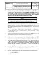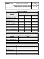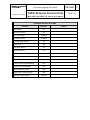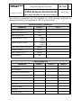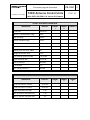
1
TYPE: NO: Firmware Upgrade Procedure TITLE: Longview, TX Facility REV: CG-1281 C PAGE: 72XX Antenna Control Units 1 OF 18 (With VCPU 201358-01 & Version 4 Firmware) WARNING This procedure will erase the ACU NVRAM database. This includes site data, antenna parameters, the target data base, and OPT solutions. PURPOSE This procedure describes the steps for upgrading the 7200/7205/7210 Antenna Control Unit (ACU) firmware on VCPU boards (201358-01), using the Version 4 FLASH command to copy an image from a PC. SCOPE This operational procedure is applicable when upgrading factory installed Version 4 firmware on the 72xx family of Antenna Control Units (ACU) for the following: Field upgrades of VCPU (201358-01) ACU firmware. NOTE This procedure may ONLY be used to upgrade CPU boards running Version 4.XX ACU firmware. For V3.XX FLASH instructions, see document CG-5546 V2.xx does not provide support for the FLASH command EXPORT CONTROL WARNING The disclosure of this document or its contents to non-U.S. persons, or the transmission of its contents outside the United States must be in compliance with U.S. Export Laws and Regulations. The bearer of this document is under obligation to know the applicable restrictions for the dissemination of its contents that relate to U.S. Export Laws and Regulations or any other U.S. government approvals. TYPE: NO: Firmware Upgrade Procedure TITLE: Longview, TX Facility REV: CG-1281 C PAGE: 72XX Antenna Control Units 2 OF 18 (With VCPU 201358-01 & Version 4 Firmware) PERSONNEL RESPONSIBLE FOR IMPLEMENTATION Manufacturing, Project Engineering, Field Services, R&D departments as necessary, and site Maintenance Engineers upon General Dynamics recommendation only. To successfully complete this procedure you must be familiar with the terminal software on your laptop or PC and have a working knowledge of the General Dynamics SATCOM Technologies ACU product you need to program, particularly the type of CPU board used. DESCRIPTION This procedure describes the steps required to upgrade a VCPU board, using the Version 4 FLASH command to copy an image from a PC. The VCPU board has 4 Mbytes of FLASH memory for use as System PROM, mapped to the following VME addresses: $FD00 $FD10 $FD20 $FD30 0000 0000 0000 0000 … … … … FD0F FD1F FD2F FD3F FFFF FFFF FFFF FFFF --------- FLASH FLASH FLASH FLASH Bank Bank Bank Bank 0 (bootable) 1 2 3 In factory a “bootable” firmware image is programmed on Bank 0 (the first Mbyte of FLASH). The Version 4-firmware images are about 640 Kbytes in size. The method described in this procedure requires an operational ACU system running Version 4 firmware and with a RS232 serial port available to configure as a Menu Tree Remote M&C shell (MT M&C). Some preparation and planning must precede the execution of this procedure. As a minimum, you will need to obtain the following: a binary image (electronic file) of the firmware you need to duplicate. The equipment described below (and this procedure). WARNING This procedure will erase the ACU NVRAM database. This includes site data, antenna parameters; the target data base, and OPT solutions. Record all user parameters BEFORE executing this procedure, and then re-enter them as necessary once the new ACU firmware is operational. For that purpose a TYPE: NO: Firmware Upgrade Procedure TITLE: Longview, TX Facility 72XX Antenna Control Units REV: CG-1281 C PAGE: 3 OF 18 (With VCPU 201358-01 & Version 4 Firmware) worksheet is provided in Appendix A to facilitate recording the user parameters or if the ACU is using V4.3 or higher firmware an automatic full parameter download to a PC is available (Reference GDST Document #CG-1295). This is extremely important in the case of upgrades to ACU systems already in service. TYPE: NO: Firmware Upgrade Procedure TITLE: CG-1281 C PAGE: 72XX Antenna Control Units Longview, TX Facility REV: 4 OF 18 (With VCPU 201358-01 & Version 4 Firmware) TECHNICAL SUPPORT Read over the following procedure before attempting to program your VCPU. If there are any questions concerning this procedure, or technical support is needed, please contact General Dynamics SATCOM Technologies (903)295-1480 or send a fax to the attention of the Technical Support department at (903)295-1479 or email at [email protected] (Website is www.gdsatcom.com). EQUIPMENT REQUIRED Phillips screwdriver for #10-32 screws A VertexRSI 72XX ACU with V4.XX firmware Laptop or PC with available serial port and terminal software (i.e. Tera Term, ProComm, HyperTerminal, etc.) capable of binary data transfers using Xmodem with CRC checksums. The laptop or PC must have the binary image (electronic file) of the upgrade on a hard disk (not a floppy drive). An RS-232 serial communication cable. The pin out of the interconnecting cable must be set up as follows: D-sub 9-pin female D-sub 25-pin male Modular wire color Connect to PC Connect to CPU 2 2 Black 3 3 Yellow 5 7 Green TYPE: NO: Firmware Upgrade Procedure TITLE: Longview, TX Facility REV: CG-1281 C PAGE: 72XX Antenna Control Units 5 OF 18 (With VCPU 201358-01 & Version 4 Firmware) PROCEDURE 1. Record all user parameters in ACU NVRAM using the worksheets contained in Appendix A OR the parameters can be downloaded using the DOWNLOADPARAMS command per GDST procedure CG-1295 (the DOWNLOAD-PARAMS command is only available in firmware version 4.3 or higher). WARNING This procedure will erase the ACU NVRAM database. This includes site data, antenna parameters, the target data base, and OPT solutions. Make sure the ACU parameters have been properly recorded in the preceding worksheet. WARNING This procedure must be performed with the system in STANDBY. All tracking operations must be halted prior to proceeding. 2. Place the ACU in Standby mode. 3. FLASH memory on the VCPU is protected by DIP switch settings. To enable writing to FLASH memory it is necessary to access the front of the CPU board and change DIP switches. a) Attain access to the top cover of the 7200 ACU. b) Remove the screws in front of the hinge, near the edges of the top cover. c) Open the top cover of the ACU chassis (or the Servo Control Unit on 7210 systems). d) Locate DIP switch number S6 on the front left side of the printed circuit board (PCB). Set DIP switch S6 1,2,3,4 to the ON position to enable writing to FLASH memory. The VCPU board (201358-01) is located in slot 1 of the VME card cage and the front panel looks like this: TYPE: NO: Firmware Upgrade Procedure TITLE: Longview, TX Facility REV: CG-1281 C PAGE: 72XX Antenna Control Units 6 OF 18 (With VCPU 201358-01 & Version 4 Firmware) Hex Rotary Switch S2 – This rotary switch is used to determine which firmware to run when the system is powered on. The VCPU contains enough flash memory to hold four unique versions of application code (each of these four allocations in memory is referred to as a boot bank). This is useful when upgrading the 7200 ACU firmware because the new image can be uploaded to another boot bank, the rotary switch can be changed, and the ACU can be booted up with the new application firmware without erasing the original factory supplied application code. The rotary switch positions and their respective functions are defined in the table below: TABLE 2-2 VCPU S2 HEX ROTARY SWITCH POSITIONS DEFINITION S2 SWITCH POSITION DESCRIPTION 0 (Factory Setting) On power-up, run the application firmware contained in boot bank 0. 1 On power-up, run the application firmware contained in boot bank 1. 2 On power-up, run the application firmware contained in boot bank 2. 3 On power-up, run the application firmware contained in boot bank 3. 4-D Unused (currently these positions are treated like position E). On power-up, run the MONDO Monitor program. MONDO is a low level monitor program used by VertexRSI to power-up, test and program a new 7200 ACU. MONDO uses an ASCII based protocol to interface with a PC via a terminal program via serial port 0 (front panel display or serial port 1 – J14 on the rear of the 7200). E F On power-up, run the Swift X talker (Used by VertexRSI software developers only) DIP Switch S6 – This DIP switch directly controls various hardware related board functions as defined in the following table: TABLE 2-4 S6 SWITCH POSITION VCPU S6 DIP SWITCH POSITIONS DEFINITION OFF POSITION (SWITCH OPEN) ON POSITION (SWITCH CLOSED) 1-4 Flash Write Disabled Flash Write Enabled 5 EEPROM Write Disabled EEPROM Write Enabled 6 Normal Operation Hold the VCPU board in Reset 7 CPU Watchdog Disable CPU Watchdog Enable 8 Board Reset Disabled Board Reset Enabled Denotes the normal operating position of the switch (factory setting). To program the flash boot banks with new application code, S6 pos 1-4 must be in the ON position; after programming is complete, return these four switches to the OFF position. TYPE: NO: Firmware Upgrade Procedure TITLE: Longview, TX Facility 4. REV: CG-1281 C PAGE: 72XX Antenna Control Units 7 OF 18 (With VCPU 201358-01 & Version 4 Firmware) Connect the PC or laptop RS-232 port to an RS-232 port (typically Port 1 – J14 connector on the rear of the 7200) on the CPU using the RS-232 Serial Communication Cable referenced in the EQUIPMENT REQUIRED section in this document. Typically, the 7200 ACU utilizes RS-422 on ports 3-7. 7205 and 7210 systems may have custom port configurations. Port 0 is always reserved for the front panel console and should not be used. NOTE On most laptops COM1: is the only available serial port (RS-232); if using a PC make sure to connect to the correct COM port. Make sure the communications parameters in the terminal program match those of the ACU. The ACU communications parameters are found in the Edit System configuration/Remote Port configuration Menu. Recommended settings are: Port = 1 (or 2), Baud = 38400, Parity = None, Data bits = 8, Stop bits = 1, Shell = MT M&C, Echo = Enabled, Newline = CRLF, Handshake = None and Screen lines = 20. 5. Confirm communications are working by pressing the ENTER key on the terminal program; the ACU should respond with a prompt ‘>’. 6. Further confirm that communications are working by entering the HELP command and verify that the ACU responds by sending the help screen text. 7. The FLASH memory is partitioned into four banks (0-3). Each FLASH bank is 1 MB in size; therefore each bank may contain a complete ACU firmware image. FLASH bank 0 is programmed in factory by Vertex and cannot be changed with this procedure. FLASH banks 1, 2 and 3 can be used for firmware upgrades. 8. From the 72XX ACU front panel, set the User Level of the ACU to Monitor mode. This is found under Set User level (and Passwords)… menu. 9. From the terminal program type (All commands shown are case sensitive): > SU 0 <ENTER> > TYPE: NO: Firmware Upgrade Procedure TITLE: Longview, TX Facility REV: CG-1281 C PAGE: 72XX Antenna Control Units 8 OF 18 (With VCPU 201358-01 & Version 4 Firmware) This is a request for the M&C port to enter Supervisor mode. If your system uses a security password the 0 in the SU command will need to be replaced by the numeric password. Verify that you are in Supervisor mode by typing: > WHO <ENTER> > 10. Look at the VCPU board inside the ACU chassis or inside the Servo Control Unit (SCU) in 7210 systems. Verify the position of rotary Switch 2 (mounted on the front edge of the board). The location of Switch 2 dictates which FLASH bank is used when the ACU boots up. When using the FLASH command in the next step DO NOT upload the new firmware into the current bank that is currently in use by the ACU. 11. From the terminal program type: > FLASH 1 <ENTER> > The number 1 in this command is the FLASH bank you wish to program (i.e. you can use 2 or 3 as well). 12. The ACU will respond with “Erasing Flash bank #:”. Then the ACU will erase the FLASH bank specified by the FLASH command in the previous step. 13. When the ACU has finished erasing the selected FLASH bank (this takes approximately 10 seconds), the ACU will then respond with “Start XMODEM send.” 14. Using the terminal program, send the file using a binary transfer using XMODEM protocol, with CRC checksums. For example, using Windows Terminal the XMODEM/CRC should be selected under the Settings/Binary Transfers… menus; and the image should be sent using the Transfers/Send Binary file…menu. NOTE The ACU sill be sending a “C” character to the terminal program about every 6 seconds. After sending 11 “C”s in the ACU will timeout on waiting for the upload and abort the process with the following message “Transfer canceled.” Sample sessions follow, including a timeout example followed by a successful transfer: TYPE: NO: Firmware Upgrade Procedure TITLE: Longview, TX Facility REV: CG-1281 C PAGE: 72XX Antenna Control Units 9 OF 18 (With VCPU 201358-01 & Version 4 Firmware) > >SU 0 >WHO Port 2 at supervisor >FLASH 1 Erasing flash bank #:-----: Start XMODEM send. CCCCCCCCCCC Transfer canceled Update not successful >FLASH 1 Erasing flash bank #:-----: Update successful. > NOTE The FLASH command takes approximately 4 minutes to complete, at a baud rate of 38400. 15. After the upload is complete, the ACU will return the message “ Update Successful.” if the command was successful. Change rotary Switch 2 on the VCPU board to the number of the FLASH bank into which you downloaded the image (i.e. if you used a FLASH 1 command turn the rotary switch S2 to 1). 16. Press the Reset Button S1 on the front of the VCPU board. 17. To confirm this procedure was performed successfully and that the ACU is using the correct firmware, simply view the firmware revision information provided in the Display System Status… Firmware Version Information screen. 18. Enable FLASH memory protection by returning DIP switch S6 1,2,3,4 to it’s original position (OFF). 19. Navigate the 7200 menu system to Edit System Configuration/Factory Tests/Reset the ACU to ROM defaults. Select YES and press Enter. 20. Enter all the user parameters previously recorded in the worksheet (See Appendix A) or upload the parameters per the instructions contained in CG1295. 21. The ACU firmware upgrade is complete. TYPE: NO: Firmware Upgrade Procedure CG-1281 TITLE: Longview, TX Facility REV: C PAGE: 72XX Antenna Control Units 10 OF 18 (With VCPU 201358-01 & Version 4 Firmware) Appendix A Worksheet to manually record the parameters. Firmware version 4.3 or higher enables the user to download the parameters to a PC as an alternative to manually filling out the tables below (Reference GDST Document #CG-1295 72xx Parameter Download/Upload Procedure) TRACKING RECEIVER SETUP PARAMETER VALUE Frequency RF input Attenuation [dB] Receiver controller 0 dB setting A/D slope STEPTRACK DEFAULTS PARAMETER DEFAULT Cycle time 00:02:00 Receive -3 dB beamwidth [deg] 0.45 Step size [deg] 0.040 Position deadband [deg] 0.040 Maximum no. of cycles 5 Cycle to start rate estimates 3 Peaking correction limit (%BW) 30 Weight adjustment value 1.00 Low tracking signal level [dB] -10.00 dB Signal threshold [dB] 15.00 dB Axis to peak first Elevation # of samples 10 Sun outage protection Enabled VALUE TYPE: NO: Firmware Upgrade Procedure CG-1281 TITLE: PAGE: 72XX Antenna Control Units Longview, TX Facility REV: 11 OF 18 (With VCPU 201358-01 & Version 4 Firmware) POSITION ENCODER CONFIGURATION PARAMETERS PARAMETER AZ EL POL Encoder direction Current position [deg] Offsets [deg] Encoder type 2-speed internal alignment (Only in systems with Encoder type set to 2-speed resolvers. ) MOTION LIMITS PARAMETERS PARAMETER DEFAULT Soft limits VALUE Enabled Lower/CCW soft limits [deg] AZ: EL: POL: 100.00 0.00 -90.00 Upper/CW soft limits [deg] AZ: EL: POL: 260.00 90.00 90.00 Motion errors Disabled Immobile/reversed timeout [ms] AZ: EL: POL: 2000 2000 2000 Immobile/reversed tolerance [deg] AZ: EL: POL: 0.02 0.02 0.20 Runaway angle [deg] AZ: EL: POL: 0.1 0.1 0.2 Velocity error timeout [ms] AZ: EL: 2000 2000 AZ: EL: 20 20 (Used only for dc/ac flux vector motor control.) Velocity error tolerance [%] C TYPE: NO: Firmware Upgrade Procedure TITLE: Longview, TX Facility REV: CG-1281 PAGE: 72XX Antenna Control Units 12 OF 18 (With VCPU 201358-01 & Version 4 Firmware) MOTION LIMITS PARAMETERS PARAMETER (Used only for dc/ac flux vector motor control.) DEFAULT VALUE C TYPE: NO: Firmware Upgrade Procedure TITLE: CG-1281 PAGE: 72XX Antenna Control Units Longview, TX Facility REV: 13 OF 18 (With VCPU 201358-01 & Version 4 Firmware) POSITION LOOP PARAMETERS VALUE PARAMETER AZ EL Gain crossover [1/sec*1000] Integral break [1/sec*1000] Filter break [rad/sec*1000] Velocity limit [deg/sec] Acceleration limit [deg/sec^2] Positioning deadband [deg] Velocity deadband [deg/sec] Jacksaver Track -> stop coast time [ms] Inching on time [ms] ADDITIONAL POSITION LOOP PARAMETERS (AVAILABLE IN SYSTEMS WITH AUXILLARY DRIVES) PARAMETER VALUE Slew rate Slew -> track transition [deg] Slew -> stop coast time [ms] SITE DATA PARAMETERS PARAMETER Antenna Name E. Longitude of site [deg] N. Latitude of site [deg] Site altitude [meters] Timezone offset Timezone abbreviation VALUE POL C TYPE: NO: Firmware Upgrade Procedure CG-1281 TITLE: Longview, TX Facility REV: PAGE: 72XX Antenna Control Units 14 OF 18 (With VCPU 201358-01 & Version 4 Firmware) RF/Geometry PARAMETERS PARAMETER VALUE Polarization axis Antenna droop correction Amplitude droop corr. [deg] Elevation alignment [deg] REMOTE PORT CONFIGURATION PARAMETER Port bps (baud) Parity Data bits Stop bits Shell Echo Newline Checksums Screen lines Port 1 Port 2 Port 3 Port 4 C TYPE: NO: Firmware Upgrade Procedure CG-1281 TITLE: Longview, TX Facility PAGE: 72XX Antenna Control Units (With VCPU 201358-01 & Version 4 Firmware) INTERFACE OPTIONS SETTINGS OPTION DEFAULT UTC display On Local time display On UTC date format dd Mmm Local date format dd Mmm Tracking signal display On Signal units dB User level display On Confirm tracking On Confirm edits On Warning bell On Audible alarm On Monitor can [STOP]/[RESUME] YES Monitor can clear defaults YES YES/NO default answer YES Always show target position NO Command angle display REV: Position VALUE 15 OF 18 C TYPE: NO: Firmware Upgrade Procedure CG-1281 TITLE: Longview, TX Facility REV: C PAGE: 72XX Antenna Control Units 16 OF 18 (With VCPU 201358-01 & Version 4 Firmware) The following parameters are only available on 7210 systems configured for Monopulse tracking (not applicable to 7200 and 7205 ACUs). MONOPULSE GLOBAL PARAMETERS PARAMETER DEFAULT Nominal gain value 200000 Maximum rotation value 45.0 Maximum gain ratio 1.000 Negate RF Input 1 error(s) e1: e2: Disabled Disabled Negate RF Input 2 error(s) e1: e2: Disabled Disabled Error coupler rotation correction Disabled Rotation direction Forward Direct position control Disabled Gain multiplier VALUE 0.60 TARGET PARAMETERS PARAMETER Target name Tracking Mode Box Center Longitude [deg E] Longitude range [deg] Estimated inclination [deg] Box limit Orbit scan Frequency [MHz] RF input Attenuation [dB] TARGET 1 TARGET 2 TARGET 3 TYPE: NO: Firmware Upgrade Procedure CG-1281 TITLE: Longview, TX Facility REV: PAGE: 72XX Antenna Control Units 17 OF 18 (With VCPU 201358-01 & Version 4 Firmware) TARGET STEPTRACK PARAMETERS PARAMETER DEFAULT Cycle time 00:02:00 Receive -3 dB beamwidth [deg] 0.45 Step size [deg] 0.040 Position deadband [deg] 0.040 Maximum no. of cycles 5 Cycle to start rate estimates 3 Peaking correction limit (%BW) 30 Weight adjustment value 1.00 Low tracking signal level [dB] -10.00 dB Signal threshold [dB] 15.00 dB Axis to peak first Elevation # of samples 10 Sun outage protection Enabled TARGET 1 TARGET 2 TARGET 3 TARGET 1 TARGET 2 TARGET 3 OPT PARAMETERS PARAMETER DEFAULT Cycle time with ST solution 00:10:00 Cycle time with LT solution 00:20:00 Signal fluctuation limit [dB] 0.20 Min. ST solution time span [hrs] 1.25 Min. LT solution time span [hrs] 18 C TYPE: NO: Firmware Upgrade Procedure CG-1281 TITLE: Longview, TX Facility REV: C PAGE: 18 OF 18 72XX Antenna Control Units (With VCPU 201358-01 & Version 4 Firmware) ADVANCED OPT PARAMETERS PARAMETER DEFAULT ST discard point 0.10 LT discard point 0.09 dB collect cycle time [ms] 500 ms (0.5 sec) Propagator cycle time [ms] 1000 ms (1 sec) Max solution RMS 0.10 (10% beamwidth) Max steptrack fit [db] 0.50 Max steptrack std [db] 0.20 Use solutions Enabled TARGET 1 TARGET 2 TARGET 3 NON-GEOSYNCHRONOUS SUPPORT PARAMETERS PARAMETER DEFAULT Non-geosynchronous tracking Disabled Orbital period [seconds] 86164.09 seconds Orbital eccentricity 0.00000 Orbit argument of perigee [deg] 0.000 Rev C – Updated ECW STMT Rev B – updates to params Rev A - Original Release Rev. No/change B. Tanner M. Neely D. Harding M. Neely Revised By TARGET 1 9/1/10 1-16-06 9-23-03 9-17-02 Date TARGET 2 D. Fredrickson D. Harrison B. Harris D. Harding Approved By TARGET 3 9/1/10 1-16-06 9-23-03 9-17-02 Date 9722 6311 4812 4254 ECO#