1
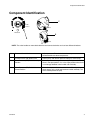
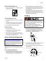
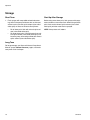
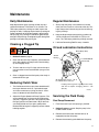
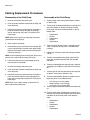
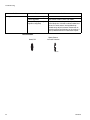
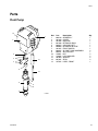
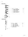
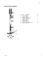
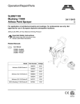
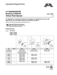
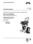
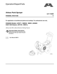
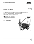
Operation/Repair/Parts
3A1187E
Airless Paint Sprayer
EN
For application of architectural paints and coatings. For professional use only.
Airlessco - GS6250 (24F575), (16M532)
3000 psi (20.7 MPa, 207 bar) Maximum Working Pressure
Important Safety Instructions
Read all warnings and instructions in this
manual. Save these instructions.
Related Manuals
Gun Manual
Model 24F575
Model 16M532
312363
312364
312365
3A0413
ti15986a
Warnings
Warnings
The following warnings are for the setup, use, grounding, maintenance, and repair of this equipment. The exclamation point symbol alerts you to a general warning and the hazard symbols refer to procedure-specific risks. When
these symbols appear in the body of this manual, refer back to these Warnings. Product-specific hazard symbols and
warnings not covered in this section may appear throughout the body of this manual where applicable.
WARNING
WARNING
FIRE AND EXPLOSION HAZARD
Flammable fumes, such as solvent and paint fumes, in work area can ignite or explode. To help prevent
fire and explosion:
• Use equipment only in well ventilated area.
• Do not fill fuel tank while engine is running or hot; shut off engine and let it cool. Fuel is flammable and
can ignite or explode if spilled on hot surface.
• Eliminate all ignition sources; such as pilot lights, cigarettes, portable electric lamps, and plastic drop
cloths (potential static arc).
• Keep work area free of debris, including solvent, rags and gasoline.
• Do not plug or unplug power cords, or turn power or light switches on or off when flammable fumes are
present.
• Ground all equipment in the work area. See Grounding instructions.
• Use only grounded hoses.
• Hold gun firmly to side of grounded pail when triggering into pail.
• If there is static sparking or you feel a shock, stop operation immediately. Do not use equipment until
you identify and correct the problem.
• Keep a working fire extinguisher in the work area.
SKIN INJECTION HAZARD
High-pressure spray is able to inject toxins into the body and cause serious bodily injury. In the event that
injection occurs, get immediate surgical treatment.
• Do not aim the gun at, or spray any person or animal.
• Keep hands and other body parts away from the discharge. For example, do not try to stop leaks with
any part of the body.
• Always use the nozzle tip guard. Do not spray without nozzle tip guard in place.
• Use Airlessco nozzle tips.
• Use caution when cleaning and changing nozzle tips. In the case where the nozzle tip clogs while
spraying, follow the Pressure Relief Procedure for turning off the unit and relieving the pressure
before removing the nozzle tip to clean.
• Do not leave the unit energized or under pressure while unattended. When the unit is not in use, turn
off the unit and follow the Pressure Relief Procedure for turning off the unit.
• Check hoses and parts for signs of damage. Replace any damaged hoses or parts.
• This system is capable of producing 3000 psi. Use Airlessco replacement parts or accessories that are
rated a minimum of 3000 psi.
• Always engage the trigger lock when not spraying. Verify the trigger lock is functioning properly.
• Verify that all connections are secure before operating the unit.
• Know how to stop the unit and bleed pressure quickly. Be thoroughly familiar with the controls.
2
3A1187E
Warnings
WARNING
WARNING
EQUIPMENT MISUSE HAZARD
Misuse can cause death or serious injury.
• Always wear appropriate gloves, eye protection, and a respirator or mask when painting.
• Do not operate or spray near children. Keep children away from equipment at all times.
• Do not overreach or stand on an unstable support. Keep effective footing and balance at all times.
• Stay alert and watch what you are doing.
• Do not leave the unit energized or under pressure while unattended. When the unit is not in use, turn
off the unit and follow the Pressure Relief Procedure for turning off the unit.
• Do not operate the unit when fatigued or under the influence of drugs or alcohol.
• Do not kink or over-bend the hose.
• Do not expose the hose to temperatures or to pressures in excess of those specified by Airlessco.
• Do not use the hose as a strength member to pull or lift the equipment.
PRESSURIZED ALUMINUM PARTS HAZARD
Use of fluids that are incompatible with aluminum in pressurized equipment can cause serious chemical
reaction and equipment rupture. Failure to follow this warning can result in death, serious injury, or
property damage.
• Do not use 1,1,1-trichloroethane, methylene chloride, other halogenated hydrocarbon solvents or
fluids containing such solvents.
• Many other fluids may contain chemicals that can react with aluminum. Contact your material supplier
for compatibility.
MOVING PARTS HAZARD
Moving parts can pinch, cut or amputate fingers and other body parts.
• Keep clear of moving parts.
• Do not operate equipment with protective guards or covers removed.
• Pressurized equipment can start without warning. Before checking, moving, or servicing equipment,
follow the Pressure Relief Procedure and disconnect all power sources.
CARBON MONOXIDE HAZARD
Exhaust contains poisonous carbon monoxide, which is colorless and odorless. Breathing carbon
monoxide can cause death.
• Do not operate in an enclosed area.
TOXIC FLUID OR FUMES HAZARD
Toxic fluids or fumes can cause serious injury or death if splashed in the eyes or on skin, inhaled, or
swallowed.
• Read MSDSs to know the specific hazards of the fluids you are using.
• Store hazardous fluid in approved containers, and dispose of it according to applicable guidelines.
3A1187E
3
Warnings
WARNING
WARNING
BURN HAZARD
Equipment surfaces and fluid that’s heated can become very hot during operation. To avoid severe burns:
• Do not touch hot fluid or equipment.
PERSONAL PROTECTIVE EQUIPMENT
You must wear appropriate protective equipment when operating, servicing, or when in the operating area
of the equipment to help protect you from serious injury, including eye injury, hearing loss, inhalation of
toxic fumes, and burns. This equipment includes but is not limited to:
• Protective eye wear, and hearing protection.
• Respirators, protective clothing, and gloves as recommended by the fluid and solvent manufacturer.
4
3A1187E
Component Identification
Component Identification
C
PRIME
ti14792a
ti16292a
PRESSURE
B
A
ti16293a
NOTE: The valve handle can move both clockwise and counter clockwise and can face different directions.
A
Pressure Control Knob
Adjusts pressure. Turn clockwise to increase pressure and
counterclockwise to decrease pressure.
Prime/Pressure (PR) Relief Valve
Primes pump and relieves pressure from gun, hose and tip.
B
Prime/Pressure (PR) Relief Valve Open
Position
Relieves pressure from gun, hose and tip and primes the unit
when in the open position. It is in the Open position when there
is a wider gap between valve handle and cam body.
C
Prime/Pressure (PR) Relief Valve
Closed Position
Pressurizes system when closed. It is in the Closed position
when there is only a slight gap between handle and body. Turn
to the closed position to spray.
3A1187E
5
Operation
Operation
Pressure Relief Procedure
NOTE: If you suspect that pressure hasn’t been relieved
due to damaged Prime/Pressure Relief Valve, or other
reason, slowly loosen the tip nut or hose coupling.
To reduce risk of injury, follow this pressure relief procedure whenever you see this symbol throughout this
manual, Also, perform this procedure whenever you:
• Stop spraying
• Check or repair any part of this system
• Install or clean spray nozzle
ti16293a
1. Engage the gun trigger lock. Refer to the separate
instruction manual provided with gun for safety features and how to engage the trigger lock.
Setup
2. Turn the unit off.
3. Disengage the gun trigger lock and trigger the gun
to relieve residual fluid pressure.
Hold metal part of the gun in contact with
grounded metal pail. Use minimum pressure.
Grounding
Always ground the following components:
•
Sprayer - Connect a ground wire and clamp (supplied) to a true earth ground.
•
Fluid Hose - Use only grounded hoses.
•
Spray Gun of Dispensing Valve - Grounding is
obtained through connection to a properly grounded
fluid hose and pump.
•
Object being sprayed - According to local code.
ti15989a
4. Turn Prime/Pressure Relief Valve (PR Valve) to the
open (priming) position to relieve residual pressure.
5. Re-engage gun trigger lock and close Prime/Pressure Relief Valve.
If the spray tip or hose is clogged, follow Steps 1
through 5 above. Expect paint to splash into the
bucket while relieving pressure during Step 4.
Connect the hose and gun
1. Remove the plastic cap plug from the outlet and
screw a conductive or grounded 3000 psi spray
hose onto fluid outlet.
2. Connect an airless spray gun to the other end of the
hose. Do not install spray tip.
NOTE: Do not use thread sealer on swivel unions as
they are made to self seal.
NOTE: The 6’ whip hose should always be 3/8”.
6
3A1187E
Operation
Fill the Packing Nut/Wet Cup
•
1. Fill the Packing Nut/Wet Cup 1/3 full with Airlessco
Throat Seal Oil (TSO).
ti15987a
When changing from oil based material to water
base material, flush with mineral spirits solvent (also
called white spirit), followed by soapy water, then a
clean water flush.
•
When flushing with solvents, ground pail and gun.
•
Flush before changing colors, before fluid can dry in
the equipment, at the end of the day, before storing,
and before repairing equipment.
Flushing
Check the Engine Oil Level
1. Unscrew the oil fill plug. The dipstick is attached to
the plug.
2. Without threading the plug into place, check to be
sure the oil is up to the top mark of the dipstick.
3. If oil is needed, refer to engine manual.
Fill the Fuel Tank
1. Close the fuel shutoff valve.
2. Use only clean, fresh, well-known brands of
unleaded regular grade gasoline.
• To reduce the risk of static sparking, which can
cause fire or explosion. Always hold a metal part of
the gun firmly against the metal pail when flushing.
This also reduces splashing.
• Always remove the spray tip before flushing.
• Only metal pails, which are conductive, should be
used as solvent pails when flushing.
1. Make sure the gun trigger lock in engaged and there
is no spray tip in the gun. Refer to the separate
instruction manual provided with gun for safety features and how to engage the trigger lock.
3. Remove the fuel cap and fill tank. Be sure the air
vent in the fill cap is not plugged so fuel can flow to
the carburetor, then replace the cap.
Prime and Flush Storage Fluid
ti16028a
NOTICE
The equipment was tested with lightweight oil,
which is left in the fluid passages to protect parts.
To avoid contaminating your fluid with oil, flush the
equipment with a compatible solvent before using
the equipment for the first time.
Before beginning a new spraying project you need to
prime the sprayer and flush the storage fluid out of the
sprayer.
2. Pour enough clean, compatible solvent into a large,
empty metal pail to fill the pump and hoses.
3. Place the suction tube into the pail or place the pail
under the pump.
4. Turn Pressure Control Knob to low.
Oil- or Water-based Materials
•
When changing from water-based material to oil
based material, flush with soapy water and then
mineral spirits solvent (also called white spirit).
PRIME
HIGH PRESSURE
ti17939a
PRESSURE
3A1187E
7
Operation
5. Open the prime valve to the open - “Priming Position”. This will allow an easy start.
Open
(Priming and
Pressure Relief)
12. Disengage the gun trigger lock and squeeze the gun
trigger. At the same time, slowly turn the pressure
control knob clockwise, just enough to move liquid
at low pressure.
13. Allow the pump to operate until clean solvent comes
from the gun.
ti16293a
14. Release the trigger and engage the gun trigger lock.
6. Turn the engine ON/OFF switch to ON.
7. Move the choke toward the closed position.
8. Move the throttle lever slightly to the left.
9. Turn the fuel valve ON. Pull the start rope. Pull the
engine over against compression stroke and then let
the rope rewind slowly into the starter. Pull firmly
and rapidly to start the engine. Do NOT drop the
rope. Hold on to the handle while rewinding, or the
rope may rewind improperly and jam the assembly.
If the engine does not start, open the choke a little
more. If the engine floods, open the choke all the
way and continue cranking.
15. If you are going to start spraying, place the pump or
suction tube into the supply container. Release the
gun trigger lock and trigger the gun into another
empty, metal container, holding a metal part of the
gun firmly against the metal pail, forcing the solvent
from the pump and hose. When paint starts coming
from gun, turn pressure control knob to minimum
pressure, place prime valve in prime (open) position
and engage the gun trigger lock.
16. If you are going to store the sprayer, remove the
suction tube or pump from the solvent pail, force the
solvent from the pump and hose. Engage the gun
trigger lock. See Storage, 10.
17. Whenever shutting down the sprayer, follow Pressure Relief Procedure, page 6.
NOTICE
Throttle Lever
Choke Lever
ti14793a
Fuel Valve
10. After the engine is warm, gradually close the choke,
raise the RPM of engine slightly by moving throttle
to the left. Close the prime valve.
Closed
(Pressure)
To prevent damage and freezing during storage,
never leave water in the fluid pump
Startup
1. Prepare the material according to the material manufacturer’s recommendations.
2. Place pump or suction tube into the material container.
3. Start the sprayer.
ti15988a
11. Point the gun into the metal pail and hold a metal
part of the gun firmly against the pail. Maintain firm
metal to metal contact between gun and container.
ti10312a
8
a.
Prime Valve must be “OPEN” in the priming
position.
b.
Pressure Control Knob must be in low pressure.
c.
Turn the engine ON/OFF switch to ON.
d.
Move the choke toward the closed position.
e.
Move the throttle lever slightly to the left.
f.
Turn the fuel valve ON. Pull the start rope. Pull
the engine over against compression stroke
and then let the rope rewind slowly into the
3A1187E
Operation
starter. Pull firmly and rapidly to start the
engine. Do NOT drop the rope. Hold on to the
handle while rewinding, or the rope may
rewind improperly and jam the assembly. If the
engine does not start, open the choke a little
more. If the engine floods, open the choke all
the way and continue cranking.
g.
After the engine is warm, gradually close the
choke, raise the RPM of engine slightly by
moving throttle to the left. Close the prime
valve.
h.
Point the gun into the metal pail and hold a
metal part of the gun firmly against the pail.
Maintain firm metal to metal contact between
gun and container.
i.
Disengage the gun trigger lock and squeeze
the gun trigger. At the same time, slowly turn
the pressure control knob clockwise, just
enough to move liquid at low pressure.
4. Prime the pump.
NOTICE
Do not start engine without fluid pump having
enough fluid so that it can be primed. Running fluid
pump dry will decrease life of the pumps packings.
a.
Allow pump to operate until paint comes from
gun.
b.
Release the trigger and engage the gun trigger lock.
c.
Turn Prime Valve OPEN to the prime position
ensuring the pressure is released from the
system.
d.
Turn Pressure Control Knob to minimum pressure.
e.
Install spray tip onto gun.
f.
Close the prime valve to the pressure position.
g.
Turn the pressure control knob to desired
spray pressure.
h.
Disengage the gun safety lock and you are
ready to start spraying.
NOTE: If you spray into the paint bucket, always use the
lowest spray pressure and maintain firm metal to metal
contact between gun and container.
3A1187E
Adjust the Pressure
• To reduce the risk of injection, never hold your
hand, body, fingers or hand in a rag in front of the
spray tip when cleaning or checking for a cleared
tip. Always point the gun toward the ground or into
a waste container when checking to see if the tip is
cleared or when using a self cleaning tip.
• To stop the unit in an emergency, turn the engine
off. Then relieve the fluid pressure in the pump and
hose. See Pressure Relief Procedure, page 6
When adjusting the pressure, turn the Pressure Control
Knob clockwise to increase pressure and counterclockwise to decrease pressure. Always use the lowest pressure necessary to completely atomize the material. If
more coverage is needed, use a larger tip rather than
increasing the pressure. Check the spray pattern. The
tip size and angle determines the pattern width and flow
rate.
NOTICE
NOTE: Operating the sprayer at higher pressure than
needed wastes material, causes early tip wear, and
shortens sprayer life.
Shutdown
1. Relieve Pressure, page 6.
2. Clean the tip and gun as recommended in the separate Gun Manual supplied with the gun.
3. If spraying water-based material or a material that
could harden in the sprayer overnight, flush the
sprayer after use. See Flushing, page 7.
NOTE: To stop the unit in an emergency, turn the engine
off. Then relieve the fluid pressure in the pump and
hose. See Pressure Relief Procedure, page 6
9
Operation
Storage
Short Term
Start Up After Storage
1. Flush sprayer with compatible solvent before storing, then fill the pump and hoses with an oil based
solvent such as mineral spirits solvent (also called
white spirit) or Graco or Airlessco Pump Armor.
Before using water-base paint, flush sprayer with soapy
water and then a clean water flush. When using oil-base
paint, flush out the mineral spirits solvent (also called
white spirit) with the material to be sprayed.
•
•
For oil base paint: flush with mineral spirits solvent (also called white spirit)
For water-base paint: flush with water, then mineral spirits solvent (also called white spirit) and
leave the pump, hose and gun filled with mineral
spirits solvent (also called white spirit).
NOTE: Always store unit indoors.
Long Term
For longer storage, use Graco or Airlessco Pump Armor.
Shut off sprayer, Relieve Pressure, page 6, and make
sure prime valve is left open.
10
3A1187E
Maintenance
Maintenance
Daily Maintenance
Regular Maintenance
Keep displacement pump packing nut/wet cup lubricated with Airlessco Throat Seal Oil at all times. The
TSO helps protect the packings and rod. Inspect the
packing nut daily. If seepage of paint into the packing nut
and/or movement of the piston upward is found (while
not spraying), the packing nut should be tightened just
enough to stop leakage. Overtightening will damage the
packings and reduce the packing life.
1. Always stop the pump at the bottom of its stroke
when you take a break or at the end of the day. This
helps keep material from drying on the rod, damaging the packings.
2. Keep the displacement pump packing nut/wet cup
1/3 full of Airlessco Throat Seal Oil (TSO) at all
times. The TSO helps protect the packings and rod.
3. Lubricate Connecting Rod Pin every 3 months.
Cleaning a Clogged Tip
Oil and Lubrication Instructions
Bleed (Weep Hole)
1. Relieve Pressure, page 6.
Sealed
Bearing
1 oz. SAE 30W Oil semi-annually
2. Clean the front of the tip frequently (with toothbrush
only) during the day to keep material from building
up and clogging the tip.
3. To clean and clear a tip if it clogs, refer to the separate instruction manual received with your gun and
nozzle.
4. Clean a clogged standard flat tip only after the tip is
removed from the gun.
Reducing Clutch Wear
1. The first 50 feet of airless spray hose should be 3/8”,
the larger diameter works as a pulsation damper
and saves unnecessary cycling the clutch. A minimum of 100 feet of hose should be used.
2. Adjust the Engine Speed and Pump Pressure. First
set the throttle lever to the maximum RPM setting
(fully left). Trigger the gun onto a test paper to check
the spray pattern and atomization. Adjust the Pressure Control Knob until you get a good pattern.
Reduce RPM of engine to support pressure without
laboring engines.
Oil impregnated sleeve - dip in
hot 10W oil when removed
Fill plug- unit has grease in gearbox from factory
and will not require changing. (Grease - PN
301178)
ti15992a
Servicing the Fluid Pump
Fluid Pump Disconnect
1. Flush the material you are spraying, if possible.
2. Relieve Pressure, page 6. Stop the pump in the
middle of down stroke.
3. Remove the suction tube and fluid hose (if so
equipped) from the fluid pump.
4. Remove the connecting rod shield from the pump.
3A1187E
11
Maintenance
5. Remove two retaining rings (4) and slip the sleeve of
the coupling down and remove both coupling
halves. This will disconnect fluid pump from the connecting rod.
2. Insert one of the retaining rings through the packing
nut and rest the sleeve on top of it.
6. Using a 7/8” box wrench disconnect the high pressure fluid line from the pump.
7. Using a 9/16” wrench, unscrew the two tie rod locknuts (10).
8. Pull the pump off the tie rods.
ti15995a
ti15996a
3. Connect the connecting rod with the fluid pump by
installing the coupling halves. Slide sleeve over the
coupling halves and secure with retaining ring.
1
2
3
ti15997a
5
12
4
4. Remove the retaining ring from the packing nut and
insert into coupling halves.
6
13
8
11
10
ti15998a
9
ti15993a
5. Secure the fluid pump housing to the tie rods and
screw locknuts with washers on loosely.
Fluid Pump Reinstall
6. Tighten the tie rod locknuts evenly to 30 ft. lb.
1. Loosen the packing nut and extend piston rod to
fully up position.
NOTE: After all the rod locknuts are tight, the alignment
of both rods should allow easy assembly and disassembly of the coupling. If any binding, loosen and retighten
all the rod locknuts to improve the alignment. Misalignment causes premature wear of seal and packings.
7. Tighten packing nut clockwise until resistance
against the packings can be felt. Turn it one full turn
more.
ti15994a
12
3A1187E
Maintenance
8. Start the pump and operate it slowly (at low engine
speed) to check the piston rod for binding. Adjust tie
rod lock nuts if necessary to eliminate binding.
Servicing the Outlet Valve
1. Complete all steps of the Fluid Pump Disconnect,
page 11.
9. Prime the unit and run at maximum pressure for
several minutes, then release the pressure and
repeat step 7.
2. Screw the suction nut off the pump and remove inlet
valve assembly.
10. Fill the wet cup (packing nut) with five drops of TSO
(Throat Seal Oil).
3. Using the rod collar tool, loosen the packing nut and
push the piston (13) down and out of the fluid body.
Servicing the Inlet and Outlet
Valves
Disassembly of the Outlet Valve
1. Using the rod collar tool (189211), screw the suction
nut (7), containing intake seat support, off of the
fluid body.
2. Remove the inlet seat (4), O-ring, inlet ball (3) and
inlet retainer (2) with O-ring.
3. Clean all parts and inspect them for wear and damage, replacing parts as needed. Old O-rings should
be replaced with new ones.
NOTE: Inlet Seat (867574) is reversible.
4. Clean inside of fluid body.
5. Reassemble the valve and screw it onto the fluid
body if no further service is needed.
4. Place piston holder (866058) in a vise. Slide piston
(13) into holder and lock in place with a 1/4” pin
(867166).
5. Clean all parts and inspect them carefully for wear
or damage. Inspect the outside of the piston rod for
scoring or wear. Replace these parts if needed. A
worn piston rod will cause premature wear of packings.
6. Using 3/8” allen wrench to unscrew retainer (8) from
piston (13).
7. Remove outlet seat (9), O-ring, outlet ball (11) and
outlet retainer (12).
8. Inspect outlet ball (11) and seat for wear. Replace
as required.
NOTE: Outlet Seat (867575) is reversible.
9. Install parts back into piston rod. Place two drops of
loctite No. 242 (blue) on threads of the retainer (8)
before assembling and torque to 20 ft-lbs.
8
1
9
10
11
2
12
13
3
4
5
867166
6
866058
7
ti15999a
3A1187E
ti16000a
13
Maintenance
Packing Replacement Procedures
Disassembly of the Fluid Pump
Reassembly of the Fluid Pump
1. Unscrew and remove the packing nut.
1. Take the lower metal male gland and place it down
on the flat side.
2. Push the piston rod down through the packings and
out of the pump.
3. Now push the packing removal tool up through the
pump and remove the top bringing the packings,
spacer and springs along with it, leaving the fluid
body empty.
NOTE: Make sure all packings and glands have been
removed from the fluid pump.
2. Take three of the lower polyethylene V-packings and
tow of the leather V-packings and place onto the
male gland, with the inverted side down, in the following order:
•
•
•
•
•
Polyethylene
Leather
Polyethylene
Leather
Polyethylene
4. Clean inside of fluid body.
5. Disassemble all parts and clean for reassembly. Discard any old packings. Save the metal upper glands.
Replace metal lower glands with new metal glands
from the packing kit.
NOTE: If the old packing had a metal gland, discard and
replace with a new plastic one from packing kit.
6. Lubricate leather packing in lightweight oil for 10
minutes prior to reassembly.
7. Unscrew and remove the packing nut.
8. Push the piston rod down through the packings and
out of the pump.
9. Now push the packing removal tool up through the
pump and remove from the top bringing the packings, spacer and springs along with it, leaving fluid
body empty.
NOTE: Make sure all old packings and glands have
been removed from fluid pump.
3. Take the female adaptor, which is inverted on both
sides, and place it on top of the assembled lower
packings.
4. Follow step 2 above, but with the packings inverted
side up.
5. Take the second lower male gland and place it on
top of the assembled packings with the rounded
side down.
6. Take the assembled glands and packings (13 pieces
all together) and slide on to the lower half of the piston.
7. Take the spacer and slide over the top of the piston
(it doesn’t matter which direction it sits).
8. Take the three Belleville Springs and slide over the
top of the piston in the following order:
• First spring, curve facing down
• Second spring, curve facing up
• Third spring, curve facing down
9. Take the upper male gland and place it rounded side
up.
10. Take the three upper polyethylene V-packings and
two leather packings and assemble with the inverted
side down on to the male gland in the following
order:
•
•
•
•
•
14
Polyethylene
Leather
Polyethylene
Leather
Polyethylene
3A1187E
Maintenance
11. Take the upper female gland and place on top of the
assembled upper packings with the inverted side
down.
Replacement of Electrical
Control Board
12. Take the assembled upper glands and packings (7
pieces) and slide over the top of the piston, making
sure the inverted sides are facing down.
1. Remove electrical cover.
13. Take the V-packing holder and replace the white
O-ring and the black O-ring with new ones form the
packing kit.
14. Slide the V-packing holder over the top of the upper
packings so they fit inside.
15. Lubricate the inside of the fluid pump body and the
outside of the packings with a lightweight oil.
2. Disconnect sensor lead from Electrical Board.
3. Disconnect two clutch leads on Electrical Board
from leads on clutch.
4. Using a 1/16” allen, loosen set screw in Pressure
Control Knob and remove knob.
5. Using a 1/2” nutdriver or 1/2” deep socket, remove
nut from pressure control shaft. This will allow
removal of electrical control board from frame.
16. Slide the completed assembly into the fluid pump
body.
6. Replace Electrical Board Assembly in reverse order.
Adjust pressure. See Pressure Calibration of the
Electrical Control Board, page 15.
NOTE: To keep packings secured in the correct position,
hold the pump body upside down and push the completed assembly upwards into the pump body. Once
placed inside, tilt the pump body back up to keep all
pieces.
Pressure Calibration of the
Electrical Control Board
17. Thread the packing nut into the top of the fluid body
and tighten hand tight.
18. Take the suction retainer and replace the black
O-ring with a new one from the packing kit. Replace
the suction ball with the new one from the kit into the
suction retainer. Place the suction seat into the flat
side of the ball guide, over the suction ball. Now
place the white O-ring into the groove around the
suction seat.
19. Take the completed suction valve assembly and
place it into the bottom of the fluid body, with the
rounded side fitting inside.
20. Take the suction seat support and place the flat side
down on the suction valve assembly (threads will be
facing upwards).
21. Thread the suction nut, over the suction seat support.
22. Tighten the packing nut (utilizing the packing nut
adjustment tool) clockwise one full turn.
1. Turn “Pressure Calibration” Trimpot adjustment on
electrical control board in the counter clockwise
direction at least 15 revolutions.
2. Connect 5000 psi glycerine pressure gauge on outlet of pump between fluid pump and airless hose to
monitor Fluid Pump Pressure.
3. Start engine and run at maximum RPM. Turn prime
Valve to open (Prime) position. Turn Pressure Control Knob to maximum position (fully clockwise).
4. Using an insulated screwdriver adjust “Pressure
Calibration” Trimpot by turning clockwise until the
clutch engages. When the clutch engages the pump
will commence Priming. When pump is primed, turn
the Prime Valve to the Closed (Pressure) Position.
NOTE: The pump will begin to pressurize and the clutch
will disengage at a low pressure. Continue turning the
trimpot clockwise to increase pressure 3000 psi.
5. Trigger gun. The pressure should drop approximately 350-400 psi, the clutch will engage and build
pressure to 3000 psi and disengage. Trigger gun
several times to ensure proper pressure setting.
6. Turn Pressure Control Knob to minimum position.
The clutch should disengage and pump stop moving.
3A1187E
15
Maintenance
7. Secure leads with tie strap.
8. Replace cover on unit. Ensure the leads are not
pinched or damaged in the process of replacing
covers.
4
BLACK
SENSOR
PRESSURE
CALIBRATION
TRIMPOT
3
BLACK
BLUE
BLACK
GREEN
BLUE
BLACK
TO CLUTCH
1
2
TO ENGINE
16
ti16006a
3A1187E
Clutch Replacement
Clutch Replacement
Removing the Clutch
Refer to the following parts diagrams: Belt Tensioning,
Clutch Assembly, and Power Unit Assembly
1. Remove the gear box cover (Power Unit Assembly,
item 1) by disconnecting fluid hose to the manifold
filter by unscrewing the four allen head bolts (Power
Unit Assembly, item 36).
2. Disconnect the Fluid Pump, page 11.
3. Pull off the spacer tubes (Power Unit Assembly, item
30) and drop the sleeve bearing down and off. Slide
the connecting rod off the gear box.
14. Hold coupling screw, with 13/16” wrench, then with
5/16” allen wrench, screw differential screw out of
coupling screw and gearbox shaft.
15. Remove the coupling screw from the clutch bore.
NOTE: After extended use the coupling screw can hang
up inside of the clutch bore. Tapping on the side of the
coupling screw and/or the use of the lightweight oil or
break free product can ease the removal process. In
extreme cases, screw the differential screw large thread
size in, then place a washer and nut on the small thread
side. This allows pulling or prying on the coupling screw
in order to remove it.
4. Remove the top cover (Power Unit Assembly, item
2) by unscrewing the 6 mounting screws. Be careful
not to lose the 6 matching grommets.
16. The clutch and other components can now be slid
off the gear box shaft.
5. Remove the bottom cover (Power Unit Assembly,
item 14) by unscrewing the 2 bolts and nuts.
Inspecting the Clutch
6. Remove the splash cover (Power Unit Assembly,
item 12) from the clutch brackets and spacer tubes.
1. Inspect clutch and belt, replace as necessary.
7. Disconnect the two clutch from the electrical control
board leads and clutch the spring (Clutch Assembly,
item 9) from the spacer tube.
Installing the Clutch
8. Loosen (do not remove completely) the block tensioner’s set screws (Belt Tensioning, item 6) to
detension the belt.
9. Loosen (do not remove) the four plate bolts.
10. Pull the cog belt loose from the engine shaft god
pulley and let hang loose on the clutch cog pulley.
11. Remove the two vertical bracket screws. (Power
Unit Assembly, item 20)
12. Remove the four horizontal screws throughout the
gearbox plate (Belt Tensioning, item 5) and lift the
gear box off the machine.
13. Place gearbox in vice by gripping the flat part of the
drive crank allowing the clutch assembly to face up.
Use caution and not allow gearbox to swing and
damage casting against vice.
Refer to the following parts diagrams: Belt Tensioning,
Clutch Assembly, and Power Unit Assembly
1. With gearbox held in a vice vertically as previously
described, place first spacer, and bearing, onto
gearbox shaft. See Clutch Assembly, page 27
2. Inspect snap rings (2), into recesses of cog pulley
portion of clutch. Place cog pulley portion of clutch
with cog belt attached onto shaft.
3. Place second spacer, into cog pulley portion of
clutch. This spacer will rest on the first bearing,
installed.
4. Insert second bearing, on top of upper snap ring.
5. Lay removable spacer on top of last bearing. If the
clutch air gap is larger than .024”, do not use removable spacer. Put spacer over removable spacer, if
used, and top bearing.
6. Place coil portion of clutch down onto cog pulley
portion of clutch and center on gearbox shaft.
3A1187E
17
Clutch Replacement
7. Screw differential screw, into coupling screw and nut
until 1/16” is showing. See Clutch Assembly, page
27
8. Push coupling nut assembly, into clutch assembly
until it comes to a positive stop. (Differential screw
comes into contact with the threaded gearbox
shaft.)
9. With 13/16” wrench on coupling screw and 5/16”
allen wrench in differential screw, simultaneously
with both wrenches screw coupling nut assembly
into gearbox shaft by turning clockwise until a positive stop is reached.
10. Hold coupling nut assembly and tighten differential
screw to 30 ft.-lbs. This will expand the coupling
assembly, thereby holding the clutch assembly to
gearbox shaft. Turn clutch observing clutch gap.
The pulley should turn freely with a gap of .012 to
.024” between the two clutch faces. If the gap is
greater than .024, remove the removable spacer.
Reassemble and check gap for proper clearance.
11. Place cog belt over cog pulley portion of clutch. Set
gearbox and clutch assembly on the support brackets (Power unit Assembly, Ref. 25 & 26), screw in
the two vertical bracket screws (Power unit Assembly, Ref. 20) and start the four horizontal screws
throughout the gearbox plate (Belt Tensioning, Ref.
25 & 26) and into the back of the gearbox.
Belt Tensioning
Refer to the following parts diagrams: Belt Tensioning,
Suction Assembly, and Power Unit Assembly
1. Slightly loosen the two horizontal screws (Power
unit Assembly, Ref. 19-22) that connect the top and
bottom supports (Power unit Assembly, Ref. 24 &
25).
2. Evenly tighten set screws (Belt Tensioning, Ref. 6)
until flush with tip of block tensioner (Belt Tensioning, Ref. 7). Check tension on cog belt by pressing
hard with thumb. Proper tensioning should allow for
approximately 1/8”. If belt is too loose, tighten set
crews further.
3. Once belt tension is correct tighten down the four
horizontal screws that go through the gearbox plate
(Power Unit Assembly, Ref. 8) and into the back of
the gearbox. Also tighten the two horizontal screws
(Power Unit Assembly, Ref. 19-20) that connect the
top and bottom supports (Suction Assembly, Ref. 24
& 25). Reconfirm that the belt deflection is still 1/8”.
4. Reassembly connections, covers and fluid pump in
reverse order as described in steps 1-7 of Removing
Clutch instructions, page 17.
12. Slide cog belt over engine pulley.
18
3A1187E
Troubleshooting
Troubleshooting
General
Problem
Cause
There is spitting from the gun.
The fluid supply is low or empty.
Refill the supply container.
Air entrapped in the fluid pump
or hose.
Check for loose connections on the siphon
assembly, tighten, then reprime pump.
The packing nut/wet cup is
loose.
Tighten just enough to stop leakage.
The upper packings are worn or
damaged.
Replace the packings. See Packing Replacement Procedures, page 14.
Worn Piston Rod.
Replace Piston Rod.
The pressure setting is too low.
Increase the pressure.
The clutch is not engaged.
See Electrical Troubleshooting.
The displacement pump is
seized.
Service the pump. See Packing Replacement Procedures, page 14.
The pressure setting is too low.
Increase the pressure.
The tip or gun filter is clogged.
Remove the tip and/or filter and clean them.
The tip is worn.
Replace tip.
The fluid displacement pump
filter is clogged.
Clean the filter.
There is a large pressure drop
in the fluid hose.
Use a larger diameter hose.
The displacement pump operates, but the output is too low
on the downstroke or both
strokes.
The inlet valve ball is not seating properly.
Service the Inlet Valve, page.
The displacement pump operates, but the output is too low
on the upstroke.
The outlet valve ball is not seating properly.
Service the Outlet Valve, page 13.
The lower packings are worn or
damaged.
Replace the Packings, page 14.
Paint leaks into the wet cup
The engine operates, but the
paint pump doesn’t cycle.
The engine and displacement
pump operates, but paint
pressure is too low or none.
3A1187E
Solution
19
Troubleshooting
Electrical
Problem
Clutch does not engage
Cause
Solution
Pressure Control Knob
Ensure the pressure control knob is in the maximum clockwise position.
Poor Electrical Connection
Remove the clutch and electrical box covers.
Check all electrical connections between the
engine magneto, sensor, control board and
clutch for loose connections or damaged leads.
Magneto
Disconnect the two leads from the control board
(blue) and the clutch assembly (black). Using a
multimeter, with the engine at maximum RPM,
pressure control knob in the maximum position
and the prime valve open (priming) position, test
the DC voltage across the boards lead (blue).
This voltage must be 13-14 VDC. If the readings
are correct, the board, sensor and magneto are
functioning. See Clutch Assembly.
When the DC voltage from the board is not
13-14 VDC, disconnect the control board lead
(black) from the engine magneto lead (pink),
located on the side of the engine. With the
engine at maximum RPM (3600), pressure control knob in maximum clockwise position and
prime valve open (priming), read the AC voltage
from the magneto lead to the sprayer frame. The
reading should be 19-24 VAC. If outside this
range, replace the magneto. If the magneto is
producing proper voltage, see Defective Sensor.
Defective Sensor
Test the sensor by reading the resistance
between the red and black wires. The resistance
runs between 1.5 - 3K ohms. A defective sensor
usually shows no resistance (open). If the reading is outside standards, replace the sensor.
An alternative method of testing the sensor is to
plug a new sensor into the board to see if the
clutch will engage. When using this method,
ensure prime/pressure valve is in the prime
position because the sensor plugged into
the board in not measuring pressure in the
fluid section.
20
3A1187E
Troubleshooting
Problem
Cause
Clutch Assembly
Solution
Measure resistance between the clutch leads
(black). This value must be 10-16 ohms. If this
reading is out of specifications, the clutch is
defective and must be replaced.
If the clutch resistance readings are correct,
check spacing between the clutch field and
plate. The gap should be .012” to .024”. If the
gap is greater than .024 the gap is too wide and
the spacer should be removed from the clutch
assembly. If the clutch still does not engage,
replace the clutch assembly. See Clutch
Replacement, page 17.
Electrical Control Board
If the magneto and sensor are functioning,
replace the electrical control board.
Airless Spray Gun
Problem
Cause
Solution
Coarse spray
Low pressure
Increase the pressure
Excessive fogging (overspray)
High pressure
Reduce the pressure to satisfactory pattern distribution.
Material too thin
Use less thinner
Pattern too wide
Spray angle too large
Use smaller spray angle tip
Pattern too narrow
Spray angle too small
Use larger spray angle tip (if coverage is OK, try
tip in same tip group)
Too much material
Nozzle too large
Use smaller nozzle
Material too thin
Pressure too high
Reduce pressure
Too little material
Nozzle too small
Use next larger nozzle
Material too thick
Thin distribution in center of
pattern “horns”
Worn tip
Change to new tip
Wrong tip
Use nozzle with narrow spray angle
Thick skin on work
Material too viscous
Thin cautiously
Application too heavy
Reduce pressure and/or use tip in next smaller
tip size
Coating fails to close and
smooth over
Material too viscous
Thin cautiously
Spray pattern irregular,
deflected
Orifice clogged
Clean carefully
Tip damaged
Replace with new tip
Craters or pock marks, bubbles on work
Solvent balance
Use 1 to 3% “short solvents remainder “long”
solvents (this is most likely to happen with material of low viscosity, lacquers, etc.)
3A1187E
21
Troubleshooting
Problem
Clogged screens
Cause
Solution
Extraneous material in paint
Clean screen
Course pigments
Use coarse screen if orifice size allows.
Poorly milled pigments (paint
pigments coagulate)
Use courser screen, larger orifice tips. Obtain
ball milled paint. If thinner had been added, test
to see if a cover screen. Incompatible drop
placed on top of paint mixes or flattens out on
the paint mixture and thinners on the surface. If
not, try different thinner in fresh batch of paint.
Test the Pattern
Good, Full
Spotty Pattern,
Increase Pressure
ti15991a
22
3A1187E
Parts
Parts
Fluid Pump
14
1
2
3
5
12
4
Ref.
1
2
3
4
5
6
7
8
9
10
11
12
13
14
Part
866143
301320
301046
867468
866074
866069
301467
866267
866241
140051
140035
301059
867641
16F587
Description
GEARBOX 1”
COVER
ROD END
RETAINING RING
COUPLING SET
RETAINING SLEEVE
FRONT SHIELD
SL PAINT PUMP ASSEMBLY
SUCTION NUT
NUT
LOCK WASHER
SPACER
STUD
LABEL, FRONT
Qty.
1
1
1
1
1
1
1
2
1
2
2
2
2
1
6
13
8
11
10
9
ti15993a
3A1187E
23
Parts
Inlet Valve
1
2
Ref.
1
2
3
4
5
6
7
3
4
5
Part
556562
866306
101822
867574
867390
866400
866241
Description
BLACK O-RING
INLET RETAINER
INLET BALL
INLET SEAT
WHITE O-RING
SUCTION FITTING
SUCTION NUT
Qty.
1
1
1
1
1
1
1
6
7
ti15999a
Outlet Valve
8
9
10
11
12
13
Ref. Part
Description
8*
866274 RETAINER
9
867575 OUTLET SEAT
10
104319 WHITE O-RING
11
867047 OUTLET BALL
12*
866307 OUTLET RETAINER
13*
187330 PISTON
* Included in Item No. 13
Qty.
1
1
1
1
1
1
ti16000a
24
3A1187E
Parts
Manifold Filter (865627)
1
Ref.
1
2
3
4
5
6
7
8
9
10
2
3
4
Part
867145
301356
867377
867214
867647
867077
301309
557391
867311
867420
Description
BASE
SPRING
O-RING
FILTER 60 MESH
SUPPORT
BASE
HOSE
PLUG 3/8”
NIPPLE 3/8”M x 1/4”M
PLUG 1/4”
Qty.
1
1
1
1
1
1
1
2
1
1
5
6
7
9
8
10
3A1187E
ti16005a
25
Parts
Packing Replacement
Ref.
1*
2
3
4
5*+
6*+
7+
8
9*
10
11+
12
13
14+
15+
16
17+
18+
19+
20+
21
22
23+
24+
25
26
27+
28+
Part
187330
866056
866295
866362
104319
866307
867047
867575
866274
866306
101822
866400
867574
867390
556562
866241
867689
866018
867693
866100
867083
866011
867688
867608
866010
866426
867378
107083
Description
Qty.
PISTON,2.00 STROKE, SL
1
SCREW,COLLAR
1
BODY,PUMP,MACHINING
1
SPACER,TUBE
1
PACKING,O-RING
1
RETAINER,BALL,.3125,SL
1
BALL,.3125, GR25, PISTON
1
SEAT,UPPER,T.C.
1
PLUG,3/4-20
1
RETAINER,SUCTION
1
BALL, INTAKE
1
SUPPORT,SUCTION SEAT
1
SEAT,T.C.
1
O-RING,5-677, PTFE
1
O-RING,-121 VITON-A 75 DURO
1
NUT,SUCTION
1
PACKING,VEE,LEATHER
4
ADAPTER,MALE, SHORT
2
PACKING,V-PACKING(1.500/1.125)
6
ADAPTER,DOUBLE, FEMALE
1
SPRING,BELLEVILLE
3
ADAPTER,MALE
1
PACKING,VEE,LEATHER
2
PACKNG,SEAL,1.187/.810,UHWPE
3
ADAPTER,FEMALE
1
HOLDER,V PACKING
1
O-RING,2-126, PTFE
1
PACKING,O-RING
1
18
17
19
2
28
20
27
26
19
17
25
24
18
23
1
22
21
4
6
7
5
8
9
14
15
3
10
11
These parts are included in Repair Kit 866267
* These parts are included in Repair Kit 866269
+ These parts are included in Packing Kit 865672
13
12
16
ti16002a
26
3A1187E
Parts
Clutch Replacement
6
7
9
5
4
3
2
1
8
10
Ref.
1
2
3
4
5
6
7
8
9
10
Part
301284
301231
305088
867602
111800
867581
301534
301208
305045
305046
Description
CLUTCH REPLACEMENT
COG BELT
SCREW
SHOULDER SCREW
SCREW FLANGED
SET SCREW
BLOCK TENSIONER
GEARBOX
PLATE
SPACER TUBE
Qty.
1
1
1
1
4
2
1
1
1
1
ti16007a
Clutch Replacement (866054)
10
5
8
9
1
Ref.
1
2
3
4
5
3A1187E
2
7
6
Part
Description
Qty.
866322 DIFFERENTIAL SCREW
1
866234 COUPLING NUT ASSEMBLY 1
CLUTCH
1
301037 BEARING
2
301274 SPACER
2
ti16008a
4
3
Ref.
6
7
8
9
10
Part
867464
301413
301412
136068
301316
Description
RETAINING RING
REMOVABLE SPACER
SPACER
SPRING
RUBBER EDGE
Qty.
2
1
1
1
1
27
Parts
Engine Assembly
4
2
1
Ref.
1
2
3
4
5
Part
114530
305012
109031
866212
555326
5
3
Description
HONDA ENGINE
ADAPTOR
SCREW
KEY
SET SCREW
6
Qty.
1
1
4
1
1
Ref.
6
7
8
9
Part
565007
866337
301229
867771
7
8
9
ti16009a
Description
SCREW
SHEAVE ASSEMBLY
THRUST PLATE
SCREW
Qty.
4
1
1
1
Frame Assembly
Ref.
1
2
3
4
5
6
7
8
9
10
11
12
1
12
2
10
11
4
5
6
8
3
9
7
28
Part
867770
301202
301165
136126
140029
867325
331048
305039
143029
110637
866084
116969
342473▲
342506▲
Description
Qty.
FRAME
1
MOTOR BRACKET
1
WHEEL
2
SCREW
4
WASHER
12
NUT
4
RUBBER BOOT
2
SPACER
2
SET COLLAR
2
SCREW
2
CUP
1
NUT
2
LABEL, WARNING (NOT SHOWN) 1
LABEL, WARNING (NOT SHOWN) 1
▲ Additional warning labels are available at no cost.
ti16011a
3A1187E
Parts
Power Unit Assembly
4
3
2
11
3
12
36
17
18
19
7
13
20
6
1
37
5
15
40
25
16
21
23
39
26
35
21
20
38
ti16010a
Ref.
1
2
3
4
5
6
7
8
9
10
11
12
13
14
15
16
17
18
19
20
21
22
23
Part
301320
301531
301135
301337
301047
301333
301446
305045
305064
305012
114530
301529
305046
109031
305067
102547
305047
140044
331294
867528
140029
867301
867325
3A1187E
Description
Qty.
GEARBOX COVER
1
TOP COVER
1
GROMMET
6
SCREW
2
SLEEVE BEARING
1
CONNECTION ROD
1
GEARBOX
1
GEARBOX MOUNTING PLATE 1
MANIFOLD HOLDER
1
ADAPTER
1
HONDA ENGINE
1
SPLASH COVER
1
TUBE SPACER
4
SCREW
2
BOTTOM COVER
1
SCREW
2
STUD
4
NUT
8
SENSOR
1
SCREW
4
WASHER
10
WASHER
4
NUT
2
Ref.
24
25
26
27
28
29
30
31
32
33
34
35
36
37
38
39
40
*
Part
Description
100450 SCREW
301299 BOTTOM SUPPORT
301232 TOP SUPPORT
301173 RETURN BRACKET
867641 STUD
140035 WASHER
140051 NUT
301059 SPACER
866069 COUPLING SET COVER
866074 COUPLING SET
867468 RETAINING RING
301467 SHIELD
867505 SCREW
121112 SCREW
305140 MANIFOLD FILTER BRACKET
867529 SCREW
301105 HOOK
866149 GROUNDING ASSEMBLY
342473▲ LABEL, WARNING (NOT SHOWN)
342506▲ LABEL, WARNING (NOT SHOWN)
Qty.
2
1
1
1
2
2
2
2
1
1
2
1
4
4
1
2
1
1
1
1
▲ Additional warning labels are available at no cost.
29
Parts
Suction Assembly (301594)
6
2
3
4
5
Ref.
1
2
3
Part
866020
867446
866388
1
Description
ELBOW
PUNCH CLAMP
HOSE 54”
Qty.
1
2
1
ti16012a
Ref.
4
5
6
Part
15F149
187147
15F513
Description
TUBE
INLET FILTER
GASKET, PAIL
Qty.
1
1
1
Paint System Assembly
9
13
10
See Packing Replacement Procedures
11
12
8
7
14
5
6
9
5
15
16
1
3
17
2
ti16003a
Ref.
1
2
3
5
6
7
8
30
Part
Description
GUN
289316
24F575
24E382 16M532
HOSE
HSE3850 3/8” x 50’ (24F575)
865675
3/8” x 50’ (16M532)
867309
NIPPLE
867311
NIPPLE
557391
PLUG
865627
MANIFOLD FILTER ASSY
301309
HOSE
Qty.
1
1
1
1
1
1
1
1
1
Ref.
9
10
11
12
13
14
15
16
17
Part
867183
301253
867325
102547
867188
867400
867660
865719
248217
15F514
16D431
867759
255439
Description
Qty.
ELBOW
MANIFOLD
1
NUT
2
BOLT
2
ELBOW
1
HOSE, PAINT 3/8” x 21”’
1
TEE
1
PRIME VALVE
1
HOSE DRAIN
1
GASKET, PAIL
1
GROMMET
1
CONNECTOR, MALE, 3/8” x 1/8” 1
HOSE 3/8” x 3’ (24F575)
1
3A1187E
Technical Data
Technical Data
Maximum working pressure . . . . . . . . . . . . . . . . . . . . . . . . . . . . . . .
Maximum delivery gpm (lpm) . . . . . . . . . . . . . . . . . . . . . . . . . . . . . .
Maximum tip size . . . . . . . . . . . . . . . . . . . . . . . . . . . . . . . . . . . . . . .
Fluid outlet npsm . . . . . . . . . . . . . . . . . . . . . . . . . . . . . . . . . . . . . . .
Wetted parts . . . . . . . . . . . . . . . . . . . . . . . . . . . . . . . . . . . . . . . . . . .
3A1187E
3000 psi (20.7 MPa, 207 bar)
1.70 (6.4)
.041 with one gun, .029 with two guns
1/4 in.
zinc and nickel-plated carbon steel, nylon, stainless steel, PTFE, acetal, leather, UHMWPE,
aluminum, tungsten carbide
31
Airlessco Standard Warranty
Airlessco warrants all equipment referenced in this document which is manufactured by Airlessco and bearing its name to be free from defects in
material and workmanship on the date of sale to the original purchaser for use. With the exception of any special, extended, or limited warranty
published by Airlessco, Airlessco will, for a period of twelve months from the date of sale, repair or replace any part of the equipment determined
by Airlessco to be defective. This warranty applies only when the equipment is installed, operated and maintained in accordance with Airlessco’s
written recommendations.
This warranty does not cover, and Airlessco shall not be liable for general wear and tear, or any malfunction, damage or wear caused by faulty
installation, misapplication, abrasion, corrosion, inadequate or improper maintenance, negligence, accident, tampering, or substitution of
non-Airlessco component parts. Nor shall Airlessco be liable for malfunction, damage or wear caused by the incompatibility of Airlessco equipment
with structures, accessories, equipment or materials not supplied by Airlessco, or the improper design, manufacture, installation, operation or
maintenance of structures, accessories, equipment or materials not supplied by Airlessco.
This warranty is conditioned upon the prepaid return of the equipment claimed to be defective to an authorized Airlessco distributor for verification
of the claimed defect. If the claimed defect is verified, Airlessco will repair or replace free of charge any defective parts. The equipment will be
returned to the original purchaser transportation prepaid. If inspection of the equipment does not disclose any defect in material or workmanship,
repairs will be made at a reasonable charge, which charges may include the costs of parts, labor, and transportation.
THIS WARRANTY IS EXCLUSIVE, AND IS IN LIEU OF ANY OTHER WARRANTIES, EXPRESS OR IMPLIED, INCLUDING BUT NOT LIMITED
TO WARRANTY OF MERCHANTABILITY OR WARRANTY OF FITNESS FOR A PARTICULAR PURPOSE.
Airlessco’s sole obligation and buyer’s sole remedy for any breach of warranty shall be as set forth above. The buyer agrees that no other remedy
(including, but not limited to, incidental or consequential damages for lost profits, lost sales, injury to person or property, or any other incidental or
consequential loss) shall be available. Any action for breach of warranty must be brought within two (2) years of the date of sale.
AIRLESSCO MAKES NO WARRANTY, AND DISCLAIMS ALL IMPLIED WARRANTIES OF MERCHANTABILITY AND FITNESS FOR A
PARTICULAR PURPOSE, IN CONNECTION WITH ACCESSORIES, EQUIPMENT, MATERIALS OR COMPONENTS SOLD BUT NOT
MANUFACTURED BY Airlessco. These items sold, but not manufactured by Airlessco (such as electric motors, switches, hose, etc.), are subject
to the warranty, if any, of their manufacturer. Airlessco will provide purchaser with reasonable assistance in making any claim for breach of these
warranties.
In no event will Airlessco be liable for indirect, incidental, special or consequential damages resulting from Airlessco supplying equipment
hereunder, or the furnishing, performance, or use of any products or other goods sold hereto, whether due to a breach of contract, breach of
warranty, the negligence of Airlessco, or otherwise.
FOR AIRLESSCO CANADA CUSTOMERS
The Parties acknowledge that they have required that the present document, as well as all documents, notices and legal proceedings entered into,
given or instituted pursuant hereto or relating directly or indirectly hereto, be drawn up in English. Les parties reconnaissent avoir convenu que la
rédaction du présente document sera en Anglais, ainsi que tous documents, avis et procédures judiciaires exécutés, donnés ou intentés, à la suite
de ou en rapport, directement ou indirectement, avec les procédures concernées.
TO PLACE AN ORDER OR FOR SERVICE, contact your Airlessco distributor,
or call 1–800–223-8213 to identify the nearest distributor.
All written and visual data contained in this document reflects the latest product information available at the time of publication.
Airlessco reserves the right to make changes at any time without notice.
Original Instructions. This manual contains English. MM 3A1187
Airlessco, 3501 N. 4th Avenue, Sioux Falls, SD 57104
Copyright 2010, Graco Inc. is registered to ISO 9001
www.airlessco.com
Revised 02/2012