1
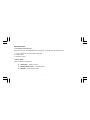
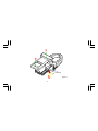
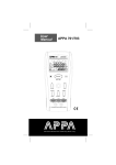
AC/DC CURRENT TRANSDUCER
INSTRUCTION MANUAL
APPA 39T
INTRODUCTION
1-1 Unpacking and Inspection
Upon removing your new Clamp Meter from its packing, you should have the following items:
1. Current Transducer with coiled cable output plugs.
2. Carrying Case.
3. Instruction manual.
1-2 Meter Safety
Terms as Marked on Equipment
ATTENTION — Refer to manual
DOUBLE INSULATION — Protection Class II.
DANGER — Risk of electric shock.
1
Symbols in this Manual
=
This symbol indicates where cautionary or other information is found in the manual.
Battery
1-3 Front Panel
Refer to Figure 1 and the following numbered steps to familiarize yourself with the meter’s front panel controls
and Connectors.
1. Red LED — Low battery display.
2. Green LED — Power on display.
3. Coiled Cable Output Leads — Voltage output.
4. Function Switch — Function select switch used to select measuring function.
5. DC Zero Button — DCA AUTO ZERO on DC current ranges.
6. Trigger — Press the lever to open the transformer jaws.
7. Transformer Jaws — Designed to pick up the a.c./d.c. current following through the conductor.
2
Figure 1
3
SPECIFICATIONS
2-1 General Specifications
Position Error
: +/- 1% of Reading.
Type Of Sensing
: Hall effect sensing for AC and DC.
Low Battery Indicator
: Red LED indicator.
Power On Indicator
: Green LED indicator , flashing.
Temperature Coefficient : 0.2 x (Spec.Acc’y) / °C , < 18°C or > 28°C .
Power Requirement
Battery Life
Max / Conductor Size
: Single 9V battery (NEDA 1604A or IEC 6LF22) (Use supplied)
: 66 hours typical (Alkaline).
: 51mm diameter or 24 x 60mm busbar.
Size
: 90mm (W) x 232mm (L) x 32mm (H).
Weight
: 420 grams
Accessories
: Coiled cable output plugs (installed) , manual and carrying case.
4
2-2 Environmental Conditions :
Indoor use.
Maximum Altitude
Installation Category
Pollution Degree
: 2000 Meter
: IEC 1010 1000V CAT. III.
:2
Operating Ambient
Storage Temperature
: 0ºC ~ 50ºC , <75%R.H.
: -20ºC ~ 60ºC, < 80% R.H.
5
2-3 Electrical Specifications
All at 23ºC ± 5ºC, less than 75% R.H.
Ranges
: 0 ~ 100A/1000A AC
0 ~ 100A/1000A DC
Accuracy
(1) DC Current :
Ranges
: 100A, 1000A
Output Voltage : 10mV / A for 100A Range
1mV / A for 1000A Range
Accuracy
: 100A Range : (0 - 100)A ±(2.9% + 2A)
1000A Range : (100 - 400)A ± (1.9% + 7A)
1000A Range : (400 - 1000)A ± (2.9% + 5A)
6
(2) AC Current :
Ranges
: 100A, 1000A
Output Voltage : 10mV / A for 100A Range
1mV / A for 1000A Range
Accuracy
: 100A Range : (0 - 100)A ±(1.9% + 2A) 40-400Hz
1000A Range : (100 - 400)A ± (1.9% + 7A) 40-400Hz
1000A Range : (400 - 1000)A ± (2.9% + 5A) 40-400Hz
Load Impendance : 100KΩ min.AC/DC
(3) Auto Power Off : Approximately 30 minutes after function changes.
7
OPERATION
This instrument has been designed and tested in accordance with IEC Publication 1010, Safety Requirements for
Electronic Measuring Apparatus and has been supplied in a safe condition. This instruction manual contains some
information and warnings which have to be followed by the user to ensure safe operation and to retain the instrument in safe condition.
3-1 Precautions and Preparations for measurement
1. Do not apply the voltage to the output plugs.
2. Make sure that the battery is connected properly.
3. Operate the instrument only in temperature between 0°C ~ 50°C and less than 75% R.H.
4. Do not use or store this instrument in high temperature or high humidity and do not store the unit in direct sunlight.
5. If the unit is not to be used for a long period of time, remove the battery.
6. Do not forget to turn power switch off after use.
7. If the meter is used near equipment that generates electro-magnetic, the output may be unstable or indicate
incorrect measurement values.
8
THIS INSTRUMENT MUST
NOT BE USED ON UNINSULATED CONDUCTORS AT A VOLTAGE
GREATER THAN 1000V ac/dc.
3-2 AC Current Measurement
1. Select the highest anticipated input (1000A or 100A) by the function switch.
2. Insert the “Output plugs (red and black)” to the input terminals of a Multimeter.
Set the Multimeter to “AC 200mV or 2V” range.
9
3-3 DC Current Measurement
1. Select the highest anticipated input (1000A or 100A) by the function switch.
2. Insert the “Output plugs (red and black) “ to the input terminals of a Multimeter.
Set the Multimeter to “DC 200mV or 2V” range.
3. Be sure to zero adjust first. With jaws closed and away from conductor, continue to press DCA AUTO ZERO
Button until instrument reads all zeroes or very close to it.
4. For DC measurement, output is positive in the red plug when the current flows from the lower side to the upper
side of the transducer as shown in Figure 2.
5. Press the trigger to open the transformer jaws and clamp one conductor only, make sure that the jaw is firmly
closed around the conductor, then read the display from the multimeter directly.
10
CURRENT
Figure 2
11
MAINTENANCE
TO AVOID ELECTRICAL SHOCK REMOVE TEST LEADS BEFORE OPENING THE COVER.
General Maintenance
1. Repairs or servicing not converted in this manual should only be performed by qualified personal.
2. Periodically wipe the case with a dry cloth and detergent do not use abrasives or solvents.
Battery Installation Replacement
The meter is powered by a single 9V battery. Refer to Figure 3 and use the following procedure to replace the battery.
1. Disconnect the output plus and turn the meter off.
2. Position the adaptor face down and remove the two screws of the case button.
3. Unsnap the case bottom and remove the battery.
4. Install a new 9V battery and refit the case button.
12
9V Battery
9V Battery
Figure 3
13
APPA TECHNOLOGY CORP.
9F.119-1 Pao-Zong Rd., Shin-Tien,
Taipai, 23115, Taiwan, R.O.C.
P.O.Box. 12-24 Shin-Tien, Taiwan.
Tel : 886-2-9178820 Fax : 886-2-9170848
E-MAIL:info @appatech.com
http://www.appatech.com
Printed In Taiwan
Copright 2001, APPA Tech., Corp. All rights reserved.