1
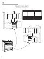
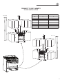
GAS/ELECTRIC RANGE
for residential use only
Models:
VEFSGE 304 SC..
R
INSTALLATION INSTRUCTIONS
IMPORTANT - PLEASE READ AND FOLLOW
•
•
•
•
•
Before beginning, please read these instructions completely and carefully.
Do not remove permanently affixed labels, warnings, or plates from the product. This may
void the warranty.
Please observe all local and national codes and ordinances.
Please ensure that this product is properly grounded.
The installer should leave these instructions with the consumer who should retain
for local inspector’s use and for future reference.
Installation must conform with local codes or in the absence of codes, the National Fuel Gas
Code ANSI Z223.1/NFPA 54 - Iatest edition. Electrical installation must be in accordance with
the National Electrical Code, ANSI/NFPA70 - latest edition and/or local codes.
IN CANADA: Installation must be in accordance with the current CAN/CGA-B149.1 National
Gas Installation Code or CAN/CGA-B149.2, Propane Installation Code and/or local codes.
Electrical installation must be in accordance with the current CSA C22.1 Canadian Electrical
Codes Part 1 and/or local codes.
INSTALLATION IN MANUFACTURED (MOBILE) HOME: The installation must conform with
the Manufactured Home Construction and Safety Standard, Title 24 CFR, Part 3280 [formerly
the Federal Standard for Mobile Home Construction and Safety, Title 24, HUD (Part 280)]
or, when such standard is not applicable, the Standard for Manufactured Home Installations,
ANSI/NCSBCS A225.1, or with local codes where applicable.
INSTALLATION IN RECREATIONAL PARK TRAILERS: The installation must conform with
state or other codes or, in the absence of such codes, with the Standard for Recreational
Park Trailers, ANSI A119.5.
Installation of any gas-fired equipment should be made by a licensed plumber. A manual
shut-off valve must be installed in an accessible location in the gas line external to the appliance for the purpose of turning on or shutting off gas to the appliance (In Massachusetts
such shutoff devices should be approved by the Board of State Examiners of Plumbers &
Gas Fitters).
If an external electrical source is utilized, the appliance, when installed, must be electrically
grounded in accordance with local codes or, in the absence of local codes, with the national
Electrical Code, ANSI/NFPA 70.
Some models are supplied with a protective film on steel and aluminium
parts. This film must be removed before installing/using the appliance.
FOR INSTALLER ONLY
THIS RANGE IS FOR RESIDENTIAL USE ONLY
WARNING !
To reduce the risk of tipping the appliance,
the appliance must be secured by properly
installed anti-tip device packed with the
appliance.
• ALL RANGES CAN TIP
• INJURY TO PERSONS COULD RESULT
• INSTALL ANTI-TIP DEVICE PACKED
WITH RANGE
• SEE INSTALLATION INSTRUCTIONS
WARNING !
If the information in this manual is not followed exactly,
a fire or explosion may result causing property damage,
personal injury, or death.
–– Do not store or use gasoline or other flammable vapors and
liquids in the vicinity of this or any other appliance.
–– NEVER use this appliance as a space heater to heat or warm
the room. Doing so may result in carbon monoxide poisoning and overheating of the appliance.
–– WHAT TO DO IF YOU SMELL GAS:
• Do not try to light any appliance.
• Do not touch any electrical switch.
• Do not use any phone in your building.
• lmmediately call your gas supplier from a neighbor’s
phone. Follow the gas supplier’s instructions.
• lf you cannot reach your gas supplier, call the fire department.
–– Installation and service must be performed by a qualified
installer, service agency, or the gas supplier.
2
DATA PLATE
The product data plate is
attached inside the bottom
pivoting panel.
CONVERSION LABEL
The Governor of California is required to publish a list of substances known to the state of California to cause cancer or reproductive harm and requires businesses to warn customers of potential
exposures to such substances.
WARNING!: Gas appliances contain or produce substances which can cause death or serious
illness and which are known to the State of California to cause cancer, birth defects or other reproductive harm. To reduce the risk from substances in fuel or from fuel combustion, make sure this
appliance is installed, operated, and maintained according to the manufacturer’s instructions.
This appliance is designed and manufactured solely for the cooking of domestic (household) food
and in not suitable for any none domestic application and therefore should not be used in a commercial environmement.
The appliance warranty will be void if the appliance is used within a none domestic environmement
i.e. a semi commercial, commercial or communal environment.
3
INSTALLATION INSTRUCTIONS
WARNING!
THIS APPLIANCE MUST BE INSTALLED BY A QUALIFIED INSTALLER.
Improper installation, adjustment, alteration, services, or maintenance can cause injury or property damage. Consult a qualified installer, service agent, or the gas supplier.
IMPORTANT: The use of suitable protective clothing/gloves is
recommended when handling, installing of this appliance.
TOOLS NEEDED FOR INSTALLATION (NOT SUPPLIED WITH THE APPLIANCE)
Screwdriver
Suitable protective
gloves
4
2 - Wrench
Hammer
T-handle
wrench
Pencil
Tape
measure
Adjustable
wrench
Adjustable
pliers
Drill
GENERAL INFORMATION
1. Installation must conform with local codes or, in the absence of local codes, with the National Fuel Gas Code, ANSI
Z223.1/NFPA 54 - Latest Edition, CAN/CGA-B149.1 or CAN/
CGA-B149.2.
2. Installation in manufactured (mobile) home: installation must
conform with the Manufactured Home Construction and
Safety Standard, Title 24 CFR, Part 3280 [formerly the Federal Standard for Mobile Home Construction and Safety,
Title 24, HUD (Part 280)] or, when such standard is not applicable, the Standard for Manufactured Home Installations,
ANSI/NCSBCS A225.1, or with local codes where applicable.
3. Installation in Recreational Park Trailers: installation must
conform with state or other codes or, in the absence of such
codes, with the Standard for Recreational Park Trailers,
ANSI A119.5.
4. To eliminate risk of burns or fire by reaching over heated surface units, cabinet storage located above the surface units
should be avoided.
5. Air curtain or other overhead range hoods, which operate by
blowing a downward air flow on to a range, shall not be used
in conjunction with gas ranges other than when the hood and
range have been designed, tested and listed by an independent test laboratory for use in combination.
WARNING!!
ELECTRICAL GROUNDING INSTRUCTIONS
The range must be electrically grounded in accordance with
local codes or, in the absence of local codes, with the National Electrical Code, ANSI/NFPA No. 70-latest edition, in Canada Canadian Electrical Code.
Installation should be made by a Iicensed electrician.
FOR PERSONAL SAFETY, THIS APPLIANCE MUST BE PROPERLY GROUNDED.
If an external electrical source is utilized, the installation must be
electrically grounded in accordance with local codes or, in the
absence of local codes, with the national Electrical Code, ANSI/
NFPA 70.
WARNING!!
6.
16. When installing or removing the range for service, a rolling lift
jack should be used. Do not push against any of the edges of
the range in an attempt to slide it into or out of the installation.
Pushing or pulling a range (rather than using a lift jack) also
increases the possibility of bending the leg spindles or the
internal coupling connectors.
This appliance shall not be used for space heating. This
information is based on safety considerations.
7. AlI openings in the wall behind the appliance and in the floor
under the appliance shall be sealed.
8. Keep appliance area clear and free from combustible materials, gasoline, and other flammable vapors.
REPLACEMENT PARTS
Only authorized replacement parts may be used in performing service on the range. Replacement parts are available from factory
authorized parts distributors. Contact the nearest parts distributor
in your area.
9. Do not obstruct the flow of combustion and ventilation air.
10. Disconnect the electrical supply to the appliance before servicing.
11. When removing appliance for cleaning and/or service;
A. Shut off gas at main supply.
B. Disconnect AC power supply.
C. Disconnect gas line to the inlet pipe.
D. Carefully remove the range by pulling outward.
CAUTION: Range is heavy; use care in handling.
12. Electrical Requirement
Electrical installation should comply with national and local
codes.
13. Air Supply and Ventilation
The installer must refers to local/national codes.
14. Gas Manifold Pressure
Natural gas - 4.0” W.C.P.
LP/Propane - 11.0” W.C.P.
15. The misuse of oven door (e.g. stepping, sitting, or leaning on
them) can result in potential hazards and/or injuries.
5
installation
1
3”
(76 mm)
PROXIMITY TO SIDE CABINETS
1. This range may be installed directly adjacent to existing 36” (914 mm)
high base cabinets.
Range dimensions:
• width: 29” 7/8 (759 mm)
MIN 35” 21/32 (905.5 mm)
MAX 36” 11/32 (923 mm)
• depth: 24” 13/64 (614.9 mm)
24
(61 ” 13/6
4.9
4
mm
)
Fig. 1.1
• height (without backguard): MIN 35” 21/32 (905.5 mm) - MAX 36”
11/32 (923 mm)
• backguard (height): 3” (76 mm)
29” 7/8
(759 mm)
Gas line opening: Wall - 37/64” (14.5 mm) from the right side to centre
of range; from 5” 7/16 (138 mm) to 6” 1/8 (155.5 mm) [depending on feet
regulation] from the floor.
Grounded outlet: should be located 37/64” (14.5 mm) from the left side
to centre of range; from 5” 7/16 (138 mm) to 6” 1/8 (155.5 mm) [depending on feet regulation] from the floor.
2. The range CANNOT be installed directly adjacent to sidewalls, tall cabinets, tall appliances, or other side vertical surfaces above 36” (914 mm)
high.
There must be a minimum of 11” 13/16 (300 mm) side clearance from the
range to such combustible surfaces TO THE LEFT or TO THE RIGHT
above the 36” (914 mm) high countertop.
IMPORTANT: One side (left or right) above the 36” (914 mm) high
countertop must always be kept clear.
Island installation: There must be a minimum of 12” (305 mm) clearance from the rear of the backguard to such combustible surface on the
back of the range above the 36” (914 mm) high countertop.
3. The maximum upper cabinet depth recommended is 13” (330 mm). Wall
cabinet above the range must be a minimum of 30” (762 mm) above the
countertop for a width of minimum 30” (762 mm): it has to be centered
with the range. Side wall cabinets above the range must be a minimum
of 18” (457 mm) above the countertop.
6
1
GAS AND ELECTRIC CONNECTION
Dotted line showing the position
of the range when installed
Ref.
inch
mm
A
5” 7/16 - 6” 1/8 (*)
138 - 155.5 (*)
B
14” 3/8
365
C
37/64”
14.5
(*) : Depending on feet regulation
C
C
B
B
A
Area for
ELECTRICAL
connection
Area for
GAS connection
Fig. 1.2
A
A
ASSEMBLING THE BACKGUARD
It is mandatory to install the backguard.
Assemble the backguard as shown in figure 1.3:
•
Screw the 2 screws “A” interposing the spacers.
•
Screw the central screw “B”.
B
Fig. 1.3
7
1
PROXIMITY TO SIDE CABINETS
STANDARD INSTALLATION
F
Fig. 1.4a
E
D
Ref.
inch
mm
A
0”
0
B
36”
914
C
11” 13/16
300
D
30” minimum
762 minimum
E
18” minimum
457 minimum
F
13” maximum
330 maximum
G
20” minimum
500 minimum
C
G
F
B
A
Fig. 1.4b
A
C
D
E
G
B
A
OVEN VENT
OVEN VENT
8
A
1
PROXIMITY TO SIDE CABINETS
ISLAND INSTALLATION
F
Fig. 1.5a
D
H
E
Ref.
inch
mm
A
0”
0
B
36”
914
C
11” 13/16
300
D
30” minimum
762 minimum
E
18” minimum
457 minimum
F
13” maximum
330 maximum
G
20” minimum
500 minimum
H
12” minimum
305 minimum
C
G
F
Fig. 1.5b
B
A
A
C
D
H
E
G
B
A
A
OVEN VENT
OVEN VENT
9
1
LEVELLING THE RANGE
The range is equipped with 4 LEVELLING FEET and may be levelled by screwing or
unscrewing the feet (figs. 1.6 - 1.7).
It is important to observe the directions of figures 1.6, 1.8a, 1.8b.
Fig. 1.6
Supplied with the range
in a separate kit
Supplied with the range
in a separate kit
0”
0 mm
+ 5/16”
+ 8 mm
+ 5/16”
+ 8 mm
Fig. 1.8a
+ 11/16”
+ 17.5 mm
Fig. 1.8b
Fig. 1.7
YOU MUST USE STABILITY
ANTI TIP BRACKET TO
PREVENT UNIT FROM
TIPPING.
ANTI-TIP STABILITY DEVICE INSTALLATION INSTRUCTIONS
1. The anti-tip bracket has to be attached as shown on figure below (only rear left side),
it has to be fixed on the floor OR on the rear wall by no. 4 (four) suitable screws (not
supplied). Alternatively the anti-tip bracket can also be fixed on the floor AND on the
rear wall by no. 8 (eight) suitable screws (not supplied).
2. After fixing the anti-tip bracket, slide range into place. Be sure the rear left foot slides
under the anti-tip bracket attached.
Dotted line showing the position
of the range when installed
ANTI-TIP STABILITY
DEVICE FIXING
3” 15/64
(82 mm)
Anti-tip stability
device
10
Rear left
feet of range
Fig. 1.9
1
INSTALLING THE COOKTOP FRONT GUARD
To increase the clearance between the front edge of the cooktop and the burners it is possible to install the cooktop front guard supplied
with the appliance.
IMPORTANT: To install/remove the guard it is necessary to remove the cooktop.
Attempting to install/remove the guard without disassembling the cooktop will result in permanent damage to the appliance.
Install the front guard as shown in figure 1.10:
1.
2.
3.
4.
5.
6.
7.
Remove the backguard.
Remove the pan supports, the burner caps and the flame spreaders.
Unscrew cooktop fixing screws (“A” in figure below).
Remove the dual burner inner flame spreader (“B” in figure below).
Remove the cooktop (keep attention not to damage the gaskets fitted above the burner cups - below the cooktop).
Install the front guard “C” by inserting the wire terminals into the proper holes above the control panel (“D” in figure below).
Reassemble the cooktop and the other components (steps from 5 to 1).
Pay special attention to the gaskets fitted above the burner cups
A
(below the cooktop); if they are damaged they shall be replaced.
A
A
A
A
A
B
B
D
D
C
Fig. 1.10
11
gas connection
2
All gas connections must be made according to national and local codes. This gas supply
(service) line must be the same size or greater than the inlet line of the appliance. Sealant on all pipe joints must be resistant to the action of LP/Propane gas.
The range is equipped for the use with NATURAL gas. It is design-certified by CSA International for NATURAL and L.P. gases with appropriate conversion.
The model/serial rating plate, located inside the bottom pivoting panel, has information
on the type of gas that can be used. If this information does not agree with the type of
gas available, check with the local gas supplier. See page from 16 to 18 for L.P. gas
conversion instructions.
1. Manual Shut-off Valve (fig: 2.1):
A manual shut-off valve must be installed in an accessible location in the gas line external
to the appliance for the purpose of turning on or shutting off gas to the appliance (In Massachusetts such shutoff devices should be approved by the Board of State Examiners of
Plumbers & Gas Fitters).
This valve should be located in the same room as the range and should be in a location
that allows ease of opening and closing (in a position where it can be reached quickly in
the event of an emergency).
Do not block access to the shutoff valve. The valve is for turning on or shutting off gas
to the appliance.
Use a new CSA or UL approved
gas supply line.
Install a shut-off valve.
Securely tighten all gas connections.
If connected to LP, have a qualified person make sure gas pressure does not exceed 14" water
column.
Examples of a qualified person
include licensed heating personnel, authorized gas company personnel, and authorized
service personnel.
Shutoff valve
“open” position
Failure to do so can result in
death, explosion, or fire.
To range
Gas supply line
Fig. 2.1
2. Pressure Regulator:
a. All heavy duty, commercial type cooking equipment must have a pressure regulator
on the incoming service line for safe and efficient operation, since service pressure
may fluctuate with local demand.
Before installing the regulator mount the 1/2” NPT (conical) male connector to the
regulator (see picture 2.2).
Gasket supplied has to be placed between 1/2” NPT (conical) connector/extension
pipe male pipe fitting (see picture 2.3).
The regulator supplied with this range must be installed before any gas connections
are made.
Use supplied pressure regulator only.
12
Explosion Hazard
2
PRESSURE REGULATOR INSTALLATION
STEP 1
Mount the 1/2” NPT (conical) male connector to the pressure regulator and
tighten by using a wrench.
Do not over tighten the connector.
Over tightening may crack regulator.
LOCK
Arrow
Fig. 2.2
STEP 2
Assemble the 1/2” NPT connector + pressure regulator group to the extension pipe interposing the gasket supplied.
The regulator cover must be oriented toward the front side of the range.
IMPORTANT: use two wrenches to tighten the connection.
Gasket
Regulator cover
Fig. 2.3
13
2
GAS CONNECTION SPEFICICATION
Range
manifold
Manifold male pipe fitting
1/2” G cylindrical
(ISO 228-1) male
Gasket
1/2” G cylindrical
(ISO 228-1) female
To range
Extension
pipe female
pipe fitting
Extension
pipe
Extension
pipe male
pipe fitting
Gasket
1/2” NPT (conical)
male
1/2” G cylindrical
(ISO 228-1) male
1/2” G cylindrical
(ISO 228-1) female
Connector
1/2” NPT
female
To mains
connection
Pressure
regulator
1/2” NPT
female
Arrow
Fig. 2.4
WARNING: check the right positioning of the gas
regulator.
The arrow on the back of the gas regulator must be
oriented toward the connector.
14
2
TEST POINT ADAPTER
The Test Point adapter is available from the
After-Sales Service.
b. Any conversion required must be performed by your dealer or a qualified licensed technician or gas service company. Please provide the service person with
this manual before work is started on the range. (Gas conversions are the responsibility of the dealer or end user.)
c. This range can be used with NATURAL or LP/PROPANE gas. It is shipped from
the factory adjusted for use with NATURAL gas.
d. Manifold pressure should be checked with a manometer and by operating as
below detailed:
•
Remove the injector from the rear left (or rear right) burner and mount the
proper test point adapter which is available from the After-Sales Service
(see side figure and the “OPERATIONS TO BE PERFORMED WHEN SUBSTITUTING THE INJECTORS” chapter).
•
Turn the rear left (or rear right) burner control knob to the maximum position.
•
Press the knob and keeping it pressed check the manifold pressure with a
manometer; NATURAL gas requires 4.0” W.C.P. and LP/PROPANE requires
11.0” W.C.P.
•
Incoming line pressure upstream from the regulator must be 1” W.C.P. higher than the manifold pressure in order to check the regulator.
•
The regulator used on this range can withstand a maximum input pressure
of 1/2 PSI (14.0” W.C.P). If the line pressure is in excess of that amount, a
stepdown regulator will be required.
e. The appliance, its individual shut-off valve, and pressure regulator must be disconnected from the gas supply piping system during any pressure testing of
that system at pressures in excess of 1/2 PSI (3.5 kPa).
f.
The appliance must be isolated from the gas supply piping system by closing its
individual manual shut-off valve during any pressure testing of the gas supply
piping system at test pressure equal to or less than 1/2 PSI (3.5 kPa).
3. Flexible Connections:
Fig. 2.5
If local codes permit, CSA or UL design-certified, flexible metal appliance connector
is recommended for connecting this range to the gas supply line. Do Not kink or damage the flexible connector when moving the range. The pressure regulator has 1/2”
NPT female pipe threads.You will need to determine the fittings required, depending
on the size of your gas supply line, flexible metal connector and shutoff valve.
4. Rigid Pipe Connections:
If rigid pipe is used as a gas supply line, a combination of pipe fittings must be used to
obtain an in-line connection to the range. All strains must be removed from the supply
and fuel lines so range will be level and in line.
•
Use joint compounds and gaskets that are resistant to action of natural or propane gas on all male pipe threads.
•
Do not over tighten gas fitting when attaching to pressure regulator. Over tightening may crack regulator.
5. Leak Testing:
IMPORTANT: Leak testing of the appliance shall be conducted as follows:
•
After final gas connection is made, turn on manual gas valve and test all connections in gas supply piping and appliance for gas leaks with a soapy water
solution. During this test all appliance gas valves have to be closed.
•
In order to avoid property damage or serious personal injury, never use a Iighted
match. If a leak is present, tighten joint or unscrew, apply more joint compound,
tighten again and retest connection for leak.
15
2
CONVERSION TO LP/PROPANE GAS (OR CONVERSION BACK TO THE
ORIGINAL GAS - NATURAL GAS)
Every range is provided with a set of injectors for the various types of gas.
Select the injectors to be replaced according to the “INJECTORS TABLE”.
The nozzle diameters, expressed in hundredths of a millimetre, are marked on the body of each injector.
CAUTION: Save the orifices removed from the appliance for future use.
SETTING THE PRESSURE REGULATOR
The pressure regulator is accessible by opening the pivoting panel (fig. 2.6); the pressure regulator is
positioned on the rear right side of the range (fig. 2.7).
To set the pressure regulator (fig. 2.7):
1. Unscrew the regulator cover.
2. Unscrew the “A” component, reverse and screw it according to the LP/PROPANE (or NATURAL GAS)
regulation.
Fig. 2.6
Pressure
regulator
Fig. 2.7
REGULATOR COVER
1
2
A
16
NATURAL GAS
REGULATION
LP/PROPANE
REGULATION
2
INJECTORS TABLE
NOMINAL
POWER
REDUCED
POWER
LP/PROPANE
11” W.C.P.
NATURAL GAS
4” W.C.P.
BTU/hr
BTU/hr
Ø injector
[1/100 mm]
Ø injector
[1/100 mm]
8000
1500
85
139
Inner crown
2100
1000
42 (*)
70 (*)
Inner & outer crown
17000
6500
115 (**)
200 (**)
BURNERS
Semirapid (SR)
Dual (D)
(*) inner crown (“J2” in figure 2.9)
(**) outer crown (“J3” in figure 2.9)
OPERATIONS TO BE PERFORMED WHEN SUBSTITUTING THE
INJECTORS
•
Remove the pan supports, the burner caps and the flame spreaders.
•
Dual burner only (fig. 2.9): Unscrew the no.3 fixing screws “A” and remove the inner
crown flame spreader “B”; then unscrew the no.2 fixing screws “C” and remove the
cover plate “D”.
Using a wrench substitute the nozzle injectors “J1”, “J2” and “J3” (figs. 2.8, 2.9) with
those most suitable for the kind of gas for which it is to be used.
•
•
Dual burner only (fig. 2.9): Refit the cover plate “D” and screw the no.2 fixing screws
“C”; then refit the inner crown flame spreader “B” and screw the no.3 fixing screws “A”
•
Refit the flame spreaders, the burner caps and the pan supports.
SEMI-RAPID BURNER
J1
The burner are conceived in such a way so as not to require the regulation of the
primary air.
Fig. 2.8
DUAL BURNER
A
A
A
C
C
B
SECOND ORIFICE
DEUXIEME ORIFICE
D
J3
J2
Fig. 2.9
17
2
SETTING THE BURNER MINIMUM
When switching from one type of gas to another, the minimum flow rate must also be correct: the flame should not go out even when passing suddenly from maximum to minimum
flame.
To regulate the flame (fig. 2.10) follow the instructions below:
Semirapid burner
• Light the burner.
•
Set the gas valve to “LO” position (minimum rate).
•
•
Remove the knob.
With a thin screwdriver, turn the regulation screw “R1” until adjustment is correct.
Inside crown of DUAL burner
• Light the DUAL burner.
” position (minimum rate of inner crown).
•
Set the gas valve to “
•
•
Remove the knob
With a thin screwdriver, turn the regulation screw “R2” until adjustment is correct.
Outside crown of DUAL burner
• Light the DUAL burner.
•
Set the gas valve to “
•
•
Remove the knob.
With a thin screwdriver, turn the regulation screw “R3” until adjustment is correct.
” position (minimum rate of inner and outer crowns).
For LP/PROPANE gas, tighten the adjustment screws completely.
After regulation repeat the operations indicated in paragraph “2. PRESSURE REGULATOR” at page 12 and 15.
If the range has been disconnected and then connected again to the gas supply line repeat the operations indicated in paragraph “5. LEAK TESTING” at page 15.
IMPORTANT:
•
After conversion to LP/PROPANE gas has been carried out affix near the data plate
the conversion label supplied and also affix a conversion label at page 3 of this instruction manual.
•
After conversion back to the original gas (NATURAL GAS) has been carried out remove, near the data plate and at page 3 of this instruction manual, the LP/PROPANE
conversion labels. Save the labels removed for future use.
R1 Regulation screw (Semirapid burner)
R2 Regulation screw (Inner crown of dual burner)
R3 Regulation screw (Outer crown of dual burner)
R3
R2
R1
18
Fig. 2.10
electrical connection
3
ELECTRICAL REQUIREMENTS
WARNING
TO AVOID ELECTRICAL SHOCK HAZARD, BEFORE INSTALLING THE
APPLIANCE, SWITCH POWER OFF
AT THE SERVICE PANEL AND LOCK
THE PANEL TO PREVENT THE POWER FROM BEING SWITCHED ON
ACCIDENTALLY.
•
This appliance must be properly installed and grounded by a qualified technician in
accordance with the National Electrical Code ANSI/NFPA No.70 (latest edition) and
local electrical code requirements.
•
This appliance may be connected by means of permanent “Hard Wiring” or “Power
Supply Cord kit”.
•
Power supply cord is not supplied, but it is available through your local electric supply house.
•
Use only 3-conductor or 4-conductor CSA/UL listed range cord rated at 30 amps with
250V minimum and provided with ring terminals. These cords should be provided
with strain relief or conduit connector.
Warning: Frame grounded through neutral lead. If used in,
–– New branch-circuit installations (1996 NEC),
–– Mobile homes,
–– Recreational vehicles, or
–– In an area where local codes prohibit grounding through neutral, use a 4 conductor cord or conduit.
•
The range must be connected to the proper electrical voltage and frequency as
specified on the rating plate.
•
The range can be connected directly to the fused disconnect (or circuit breaker box)
through flexible, counduit with copper or aluminium wiring (with grounding wire).
Allow two to three feet of slack in the line so that it can be moved if servicing is ever
necessary.
ELECTRICAL CONNECTION WITH POWER CORD
Use a 3-wire power supply cord kit rated for 30 amps - 240-208/120 volts with closed loop
terminals and marked for use with ranges.
Where local codes do not permit grounding through neutral, use a 4-wire power supply
cord.
The CSA/UL listed cord must be secured to the range with a suitable strain relief bracket.
The electrical connection is made at the terminal block, which is located behind the access door on the back of the range.
ELECTRICAL CONNECTION WITH CONDUIT
Use 1/2” (1.3 cm) trade size CSA/UL listed conduit with a conduit clamp, 16 AWG/600
volt copper conductor colored red for line 1 and black for line 2 and 16 AWG/600 volt
copper conductor (or 14 AWG/600 volt copper conductor if grounding through neutral)
colored white for neutral with closed loop terminals marked for use with ranges.
Where local codes do not permit grounding through neutral, use a green 14 AWG copper
conductor as directed in the 4-wire connector directions.
The conduit must be secured to the range with the strain relief bracket.
The electrical connection is made at the terminal block, which is located behind the access door on the back of the range.
19
3
Fig. 3.1
Screws
3-Wire Power Cord Installation (See Figure 3.2)
1. Remove the Terminal Block Access Plate on the back of the
range by unscrewing the 4 fixing Screws (Figure 3.1).
2. Check the correct positioning of the Power Cord Bracket as
per figure 3.2.
3. Assemble the strain relief in the hole on Power Cord Bracket.
4. Insert the Power Cord through the strain relief and tighten.
Screws
5. Remove the 3 wire terminal nuts and washers from the Terminal Block.
6. Plug the terminal holes of Power Cord.
The Neutral or Ground Wire of the Power Cord must be connected to the neutral terminal located in the center of Terminal
Block.
The Power Wires must be connected to the outside terminals.
7. Plug washers and tighten nuts securely.
Terminal Block
Access Plate
Do not remove Ground strap.
8. Reassemble the Terminal Block Access Plate on the back of
the range by screwing the 4 fixing Screws (Figure 3.1).
Fig. 3.2
Ground strap
Neutral Wire
B
Terminal Block
Power Cord
Bracket
4-Wire Power Cord Installation (See Figure 3.3)
1. Remove the Terminal Block Access Plate on the back of the
range by unscrewing the 4 fixing Screws (Figure 3.1).
2. Check the correct positioning of the Power Cord Bracket as
per figure 3.3.
A
A: D=1” 9/64 (29 mm)
B: D=7/8” (22.5 mm)
3. Assemble the strain relief in the hole on Power Cord Bracket.
4. Insert the Power Cord through the strain relief and tighten.
Power Cord
Power Wires
5. Remove the 3 wire terminal nuts and washers from the Terminal Block.
6. Remove the Ground Strap from the frame of range and terminal by removing its screw and cutting it as shown in Figure 3.3.
7. Plug the terminal holes of Power Cord.
The Neutral Wire of the Power Cord must be connected to the
neutral terminal located in the center of Terminal Block; the
Power Wires must be connected to the outside terminals; the
Ground Wire must be attached to the frame of range by using
the (Ground) identified Grounding Screw.
Fig. 3.3
Cut Ground Strap
Neutral Wire
B
Power Cord
Bracket
A: D=1” 9/64 (29 mm)
B: D=7/8” (22.5 mm)
Terminal Block
Grounding
Screw
A
Power Wires
20
8. Plug washers and tighten nuts securely.
Power Cord
Grounding Wire
9. Reassemble the Terminal Block Access Plate on the back of
the range by screwing the 4 fixing Screws (Figure 3.1).
3
3-Wire Conduit Installation (See Figure 3.5)
1. Remove the Terminal Block Access Plate on the back of the
range by unscrewing the 4 fixing Screws (Figure 3.4).
Fig. 3.4
Screws
2. Check the correct positioning of the Conduit Bracket as per
figure 3.5.
3. Feed 1/2” (1.3 cm) trade size Conduit through the hole in the
Conduit Bracket and secure to the Conduit Bracket with a
Conduit Clamp.
4. Plug the terminal holes of conductors.
The Neutral or Ground Wire must be connected to the neutral
terminal located in the center of Terminal Block.
The Power Wires must be connected to the outside terminals.
Screws
5. Plug washers and tighten nuts securely.
Do not remove Ground strap.
Terminal Block
Access Plate
6. Reassemble the Terminal Block Access Plate on the back of
the range by screwing the 4 fixing Screws (Figure 3.4).
Fig. 3.5
Ground strap
Neutral Wire
4-Wire Conduit Installation (See Figure 3.6)
A
Terminal Block
Power Cord
Bracket
1. Remove the Terminal Block Access Plate on the back of the
range by unscrewing the 4 fixing Screws (Figure 3.4).
2. Check the correct positioning of the Conduit Bracket as per
figure 3.6.
3. Feed 1/2” (1.3 cm) trade size Conduit through the hole in the
Conduit Bracket and secure to the Conduit Bracket with a
Conduit Clamp.
B
A: D=1” 9/64 (29 mm)
B: D=7/8” (22.5 mm)
Conduit Clamp
4. Remove the 3 wire terminal nuts and washers from the Terminal Block.
Power Wires
Conduit
5. Remove the Ground Strap from the frame of range and terminal by removing its screw and cutting it as shown in Figure 3.6.
6. Plug the terminal holes of conductors.
The Neutral Wire must be connected to the neutral terminal
located in the center of Terminal Block; the Power Wires must
be connected to the outside terminals; the Ground Wire must
be attached to the frame of range by using the (Ground) identified Grounding Screw.
Fig. 3.6
Cut Ground Strap
Neutral Wire
Terminal Block
7. Plug washers and tighten nuts securely.
8. Reassemble the Terminal Block Access Plate on the back of
the range by screwing the 4 fixing Screws (Figure 3.4).
A
Power Cord
Bracket
Grounding
Screw
B
A: D=1” 9/64 (29 mm)
B: D=7/8” (22.5 mm)
Power Wires
Conduit Clamp
Grounding Wire
Conduit
21
22
IC
ISG
OL
E61
CE
GE
TE
BE-INT
BE-EXT
TPL
IGNITION COIL
IGNITION SWITCHES GROUP
OVEN LAMP
RELAY
CIRCULAR ELEMENT
BROIL ELEMENT
TOP ELEMENT
BOTTOM ELEMENT INT.
BOTTOM ELEMENT EXT.
THERMOSTAT PILOT LAMP
ELECTRIC DIAGRAM KEY
DSPL
CF
OF
DLM
SL/U
LPL
ST
EL.P
SD
ODL
AS
DOOR SAFETY PILOT LAMP
COOLING FAN
OVEN FAN
DOOR LOCK MOTOR
STATUS LOCK/UNLOCK
LINE PILOT LAMP
SAFETY THERMOSTAT
ELECTRONIC PROGRAMMER
DOOR STATUS, OPEN/CLOSED
OVEN DOOR LATCH
AIR SWITCH
CONNECTIONS ON PROGRAMMER
PN/PL SUPPLY
K1
PROGRAM THERMOSTAT RELAY1
K2
COOLING/OVEN FAN RELAY2
K3
DOOR LOCK/UNLOCK RELAY3
PHV
FUNCTION STATE
X0
THERMOSTAT ENCODER
X1
FUNCTIONS ENCODER
P4
PROBE (Sonde)
P5B
WIRES P5B(1)+P5B(2)+P5B(3)
3
WIRING DIAGRAM
23
The manufacturer cannot be held responsible for possible inaccuracies due to printing or transcription errors in the present booklet.
The manufacturer reserves the right to make all modifications to its products deemed necessary for manufacture or commercial reasons at any moment and without
prior notice, without jeopardising the essential functional and safety characteristics
of the appliances.
Cod. 1104016 - ß3