1
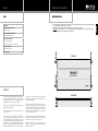
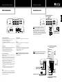
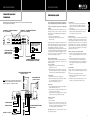
M A XXXXSSOONNIICCSS UESUAR, OI PNEC .G M B H
1290
Ensell Road
Neckarstraße
20
Lake
Zurich,
Illinois Germany
60047 USA
74847
Obrigheim,
Phone +1
54061
- 7700
+49847
(0)- 62
- 6 38-0
FAXX
54061
- 9776
FAXX +1
+49847
(0)- 62
- 6 38-129
E-Mail
E-Mail [email protected]
[email protected]
Website www.maxxsonics.com
www.mbquart.de
N A U T I C
6-Channel Amplifier NAA 665
6-Kanal Verstärker NAA 665
Installation & Operation
Einbau und Betrieb
Congratulations!
By purchasing an amplifier from MB QUART, you have decided on a
product of the highest technical quality. MB QUART wishes you great
enjoyment with your amplifier. Should you have any questions about
this system or other MB QUART products, please call us personally or
send us an e-mail at [email protected]
Herzlichen Glückwunsch!
Mit dem Kauf eines Verstärkers aus dem Hause MB QUART haben Sie
sich für ein technisch qualitativ hochwertiges Produkt entschieden.
MB QUART wünscht Ihnen viel Spaß mit Ihrem Verstärker. Sollten
Sie Fragen zu diesem oder anderen MB QUART Produkten haben,
freuen wir uns über Ihren persönlichen Anruf oder eine E-Mail an
[email protected]
M A X X S O N I C S EUUS R
AO
, PI NE CG. M B H
Neckarstraße
20
1290 Ensell Road
74847
Obrigheim,
Lake Zurich,
IllinoisGermany
60047 USA
Phone +49
(0) -62540
61 -- 7700
6 38-0
+1 847
FAXX +49
(0) -62540
61 -- 9776
6 38-129
+1 847
E-Mail [email protected]
[email protected]
Website www.mbquart.de
www.maxxsonics.com
ENGLISH
GENERAL INSTALLATION NOTES
Index
Mounting directions
1. Choose a mounting location away from direct exposure to water. We recommend that you stay as close to the marine battery as possible
to keep the power and ground cables as short as possible.
2. Use the stainless steel mounting screws and washers provided to securely fasten the amplifier.
CAUTION: Be sure there is adequate room (1” clearance) behind the chosen mounting surface for the mounting screws to protrude.
3. The rubber mounting buffers are designed to help absorb vibration.
2
GENERAL INSTALLATION NOTES
Mounting directions
3
English
WARRANTY
AMPLIFIER FEATURE DESCRIPTION
NAA 665 6-Channel Amplifier
4
AMPLIFIER APPLICATIONS
6-channel full range stereo
5
4-channel full range stereo / 1-channel mono
6
AFTER INSTALLATION
Troubleshooting a system
TECHNICAL DATA
7
38
TOP VIEW
WARRANTY
As the manufacturer of MB QUART car audio products, Maxxsonics
USA Inc. and Maxxsonics Europe GmbH warrants to the original
consumer purchaser the amplifier to be free from defects in material
and workmanship for one (1) year from date of purchase.
This product meets the current EU minimum warranty requirements,
if purchased in countries of the EU.
To ensure your warranty policy keep your original receipt proofing
the date of purchase.
All other part and accessories of the system are warrantied to be
free from defects in material and workmanship for one (1) year from
date of purchase. Maxxsonics will repair or replace at it’s option and
free of charge during the warranty period, any system component
that proves defective in materials and workmanship under normal
installation, use and service provided that the product is returned
2 to the authorised MB QUART dealer from where it was purchased.
A photo copy of the original receipt must accompany the product
being returned. In the absence of the above, the warranty is one (1)
year from date of manufacture.
SIDE VIEW
Any damage to the product as a result of misuse, abuse, accident,
incorrect wiring, improper installation, alteration of date code or bar
code labels, revolution, natural disaster, or any sneaky stuff because
someone messed up, repair or alteration out side of our factory or
authorised service centers and any thing else you have done that you
should not have done is not covered.
This warranty is limited to defective parts and specifically excludes
any incidental or consequential damages connected therewith. This
warranty is not to be construed as an insurance policy.
Warranty on installation labor, removal, re-installation and freight charges are not the responsibility of Maxxsonics USA Inc. or
Maxxsonics Europe GmbH.
3
AMPLIFIER FEATURE DESCRIPTION
AMPLIFIER APPLICATIONS
NAA 665 6-Channel Amplifier
6-channel full range stereo
CH 5 & 6
CH 3 & 4
CH 1 & 2
X-OVER
X-OVER
X-OVER
CH2
INPUT
CH4
CH5
POWER
LP HP FULL
LP HP FULL
LP HP FULL
LEVEL
LEVEL
LEVEL
LO-MED-HI
LO-MED-HI
LO-MED-HI
CH 3 & 4
CH 1 & 2
X-OVER
X-OVER
X-OVER
LP HP FULL
LP HP FULL
LP HP FULL
LEVEL
LEVEL
LEVEL
LO-MED-HI
LO-MED-HI
LO-MED-HI
L
REM BATT +12V
- ch5 +
BRIDGED
+ ch3 + ch4 BRIDGED
POWER / GROUND
This amplifier requires high quality 4 gauge power and ground cables.
LEVEL CONTROL
The LEVEL control switches allow you to selectfixed unbalanced (RCA)
input sensitivities provided by your Radio / CD player
- LO: Low accepts unbalanced input from 0.2V to 2.5V
- MED: Medium accepts unbalanced input from 2.5V to 4V
- HI: High accepts unbalanced input from 4V to 6V
SPEAKER OUTPUT
The molded speaker terminals accept 18 gauge to 12 gauge speaker
wires. We recommend 16 to 18 gauge high quality speaker wires for
full range speakers and 12 to 14 gauge
for subwoofer applications.
INPUTS
There are 3 sets (channel 1-2 / 3-4 / 5-6) of unbalanced (RCA) low
level inputs which will allow for complete control of front / rear fade
& left / right balance. Be sure to use high quality shielded RCA audio
cables for maximum signal transfer.
4
+ ch5 -
X-OVER (CROSSOVER) SWITCHES
The X-Over switches allow you to control the fixed crossover slopes
for each group of paired channels (1 & 2 / 3 & 4 / 5 & 6)
- LP: Low Pass plays 100Hz / 24dB & below
- HP: High Pass plays 100Hz / 12dB & above
- FULL: Full Range plays all frequencies controlled by the Radio/CD
player
POWER / PROTECT INDICATORS
POWER: The Power light will illuminate blue to indicate that the amp
is “ON” and ready to play
PROTECT: The Protect light will illuminate red to indicate that the
amp diagnostic circuit has detected a fault and the amp will not play
until the problem is resolved. Here is a list of Faults that will cause
the amp to shut down and go into the PROTECT mode.
- THERMAL: The internal components reach a temperature above
their allowed safe operating temperature range.
- SHORT CIRCUIT: Pinched or shorted speaker lead, shorted speaker
voice coil or shorted passive crossover provided with the component speakers.
- OVER-LOAD: Operating below proper operating impedances (4Ohms & 2-Ohms stereo and 4-Ohms mono bridged).
L
CH6
SPEAKER OUTPUT
BRIDGED
+ ch1 + ch2 -
CH5
CH1
Note: The diagram illustrates using 3 sets of RCA cables for maximum front / rear fade and left / rear balance control.
If your Radio / CD player has only 2 sets (front / rear) RCA cables,
just plug them into channels 1-4 (all 6 channels will play)
and you will still have front / rear fade and left / rear balance.
If the radio has only 1 set of RCA cables, plug them into channels
1-2 and all 6 channels will still play. You will have left / right
balance but will not have front / rear fade.
CH3
CH6
FULL RANGE STEREO
LINE INPUTS FROM
RADIO / CD PLAYER
REMOTE
The remote wire turns the amplifier on and off via the Radio/CD player “remote output” wire.
NOTE: To ensure maximum performance and sound quality, please read and the installation and wiring directions on the following pages carefully.
FULL RANGE STEREO SPEAKERS
4-Ohms Or 2-Ohms
CAUTION: This amp is capable of 4-Ohms and 2-Ohms wired in
the “stereo” mode & 4-Ohms when wired “mono bridged”. It is
not capable of 1-Ohm stereo or 2-Ohms mono bridged.
+
+
POWER
GND
+
SPEAKER OUTPUT
BRIDGED
+ ch1 + ch2 -
REM BATT +12V
- ch5 +
BRIDGED
+ ch3 + ch4 BRIDGED
CHASSIS GROUND
REMOTE TURN-ON
BATTERY + 12 VOLTS
18 gauge
4 gauge
4 gauge
40 Amp Fuse
+
+
-
+ ch6 -
+
-
POWER
GND
CH3
INPUT
CH4
R
PROTECT
CH1
CH2
POWER
R
PROTECT
CH 5 & 6
English
CROSSOVER SWITCHES IN
“FULL” (FULL RANGE)
FULL RANGE STEREO SPEAKERS
4-OHM OR 2-OHM
5
AFTER INSTALLATION
4-channel full range stereo /
1-channel mono
Troubleshooting a system
This diagram illustrates wiring 4 full range speakers wired stereo and a subwoofer wired mono bridged.
Please note position of X-Over switches.
Description of the Diagnostic system built into all MB QUART
amplifiers:
The diagnostic system will shut down the amplifier, until reset by
turning the head unit off, and back on. This state of affairs will be
indicated by the front panel PROTECT LED lighting up under the following conditions:
1 - A sort circuit on the loudspeaker leads.
2 - An internal amplifier fault that causes a DC offset on the
loudspeaker output.
CHANNELS 1 - 4 CROSSOVER SWITCHES
IN “FULL” (FULL RANGE)
CHANNELS 5 - 6 CROSSOVER SWITCH
IN “LP” (LOW PASS)
CH 5 & 6
CH 3 & 4
CH 1 & 2
X-OVER
X-OVER
X-OVER
LP HP FULL
LP HP FULL
LP HP FULL
LEVEL
LEVEL
LEVEL
LO-MED-HI
LO-MED-HI
LO-MED-HI
CH2
INPUT
CH4
CH5
POWER
PROTECT
The key to finding the problem in a misbehaving sound system is to
isolate parts of that system in a logical fashion to track down the fault.
R
L
CH1
CH3
FULL RANGE STEREO LINE INPUTS
FROM RADIO / CD PLAYER REQUIRE
A “Y-ADAPTOR” AS SHOWN
CH6
Y-ADAPTOR
FULL RANGE STEREO
LINE INPUTS FROM
RADIO / CD PLAYER
DESIGNATED MONO (SUBWOOFER)
INPUTS FROM RADIO / CD PLAYER
FULL RANGE STEREO SPEAKERS
4-Ohms Or 2-Ohms
NOTE: This amp is capable of 4-Ohms and 2-Ohms wired in the
“stereo” mode & 4-Ohms when wired “mono bridged”. It is not
capable of 1-Ohm stereo or 2-Ohms mono bridged.
+
+
-
+
POWER
GND
MONO SUBWOOFER
8-Ohms or 4-Ohms
SPEAKER OUTPUT
BRIDGED
+ ch1 + ch2 -
REM BATT +12V
- ch5 +
BRIDGED
+ ch3 + ch4 BRIDGED
CHASSIS GROUND
REMOTE TURN-ON
BATTERY + 12 VOLTS
6
18 gauge
4 gauge
4 gauge
40 Amp Fuse
+
+
-
+ ch6 -
FULL RANGE STEREO SPEAKERS
4-OHM OR 2-OHM
Should the amplifier go into diagnostic mode, simply disconnect all
RCA and speaker leads, while keeping +12 volt, power ground and
remote leads connected. Now turn the amplifier back on, and if the
diagnostic LED lights, the amplifier has an internal fault.
If not, plug the RCA cables back, and reset the amplifier. If it goes into diagnostic now, the fault lies in the input, either with bad cables or source unit.
If the amplifier seems fine with RCA cables plugged in, connect the
speakers, one at a time, and if one of the speakers or its wiring is
faulty, it will activate the diagnostic system.
Amplifier heatsink overheating:
The amplifiers will shut down when the heatsink temperature reaches
80 degrees centigrade, and turn back on once the unit has cooled
down below that point.
Causes of overheating:
1 - Inadequate cooling - relocate or remount to provide better
natural airflow over the fins.
2 - Driving high power levels into low impedances - back off on the
volume control, and/or make sure you are not loading the amplifier with less than the recommended loudspeaker impedance.
Low output power:
1 - Check that level controls have been set up properly.
2 - Make sure that the battery voltage, as measured at the amplifier’s
+12 volt and ground terminals, is 11 volts or more.
3 - Check all +12 volt and ground connections.
Hiss, or white noise:
1 - High levels of white noise usually occurs when amplifier level
controls are turned up too high - readjust according to the
procedures in section ”Setting up systems after installation for
best performance”
2 - Another major problem that can cause excessive hiss, is a noisy
head unit - unplug the amplifier input RCA cables, and if the
hiss level reduces, the source unit is at fault.
English
AMPLIFIER APPLICATIONS
Electrical interference:
The inside of an automobile is a very hostile electrical environment.
The multitude of electrical systems, such as the ignition system, alternator, fuel pumps, air conditioners, to mention just a few, create
radiated electrical fields, as well as noise on the +12 volt supply and
ground. Remember to isolate the problem - first unplug amplifier
input RCA cables, if the noise is still present, check the speaker leads,
if not, plug the RCA’s back, and investigate the source driving the
amplifier, one component at a time.
A ticking or whine that changes with engine RPM:
1 - This problem could be caused by radiation pickup of RCA cables
too near to a fuel pump or a distributor, for instance, - relocate
cables.
2 - Check that the head unit ground is connected straight to the
vehicle chassis, and does not use factory wiring for ground.
3 - Try to supply the head unit with a clean +12 volt supply directly
from the battery +, instead of using a supply from the in dash
wiring/fusebox.
A constant whine:
This type of noise can be more difficult to pinpoint, but is usually
caused by some kind of instability, causing oscillations in the system.
1 - Check all connections, especially for good grounds.
2 - Make sure that no speaker leads are shorting to exposed metal
on the vehicle chassis.
3 - RCA cables are notorious for their problematic nature, so check
that these are good, in particular the shield connections.
Fuses blowing:
1 - The use of loudspeaker impedances below the recommended minimums will draw more current - check.
2 - A short on the main +12 volt cable from the battery to the vehicle
chassis will cause the main fuse to blow.
3 - If an amplifier fuse blows continually, with only +12 volt, ground
and remote leads connected, the amplifier may be faulty.
System does not turn on:
1 - Check all fuses.
2 - Check all connections.
3 - Measure the +12 volt and remote turn on voltages at the amplifier terminals. If these are non existent or low, take voltage
measurements at fuse holders, distribution blocks, the head unit’s
+12 volt and remote leads to localize the problem.
Noise problems: System noise can be divided into two categories,
hiss, and electrical interference.
7
Deutsch
DEUTSCH
8
9
Deutsch
DEUTSCH
8
9
TECHNICAL DATA
Features
NOTES
NAA 665
6-channel
Output Power Rating (14.4V battery)
4-Ohms
65 x 6
2-Ohms
90 x 6
1-Ohm
No
Mono bridged into 4-Ohms
180 x 1
Miscellaneous Specifications
Slow unmute at turn on (soft start)
Damping factor
Yes
> 200
Signal to noise ratio (A-weighted)
> 95 dB
THD & N
< 0,05 %
Channel separation at 1 KHz
> 70 dB
Selectable-Fixed input level control
Input impedance
Power and Diagnostic LED
0.2V-6V (LO/MED/HI)
47 Kohm
Yes
Protection:
DC, short, thermal, overload
Yes
Power supply, all MOSFET PWM
Yes
Audio output, all Bipolar
Yes
Crossover and switching
Input selector switch
Channels 1/2
FULL / HP / LP
Fixed high pass, 12 db/oktave
100Hz & up
Fixed low pass, 24 db/oktave
100Hz & down
Connector types
Unbalanced inputs (RCA)
Mechanical
Molded power terminal
4 GA
Molded speaker terminals
12 GA
Fuse types
ATC
Fuse size
40 amp
Dimensions (length x width x height) inches
10
17 x 7.7 x 2
11
MAXXSONICS EUROPE GMBH
Neckarstraße 20
74847 Obrigheim, Germany
Phone +49 (0) 62 61 - 6 38-0
FAXX +49 (0) 62 61 - 6 38-129
E-Mail [email protected]
Website www.mbquart.de
MAXXSONICS USA, INC.
1290 Ensell Road
Lake Zurich, Illinois 60047 USA
Phone +1 847 - 540 - 7700
FAXX +1 847 - 540 - 9776
E-Mail [email protected]
Website www.maxxsonics.com
MAXXSONICS USA, INC.
1290 Ensell Road
Lake Zurich, Illinois 60047 USA
Phone +1 847 - 540 - 7700
FAXX +1 847 - 540 - 9776
E-Mail [email protected]
Website www.maxxsonics.com
MAXXSONICS EUROPE GMBH
Neckarstraße 20
74847 Obrigheim, Germany
Phone +49 (0) 62 61 - 6 38-0
FAXX +49 (0) 62 61 - 6 38-129
E-Mail [email protected]
Website www.mbquart.de