1
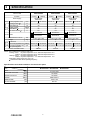
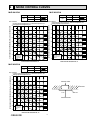
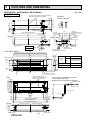
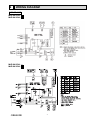
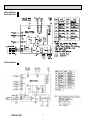
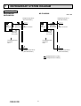
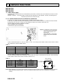
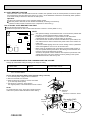
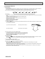
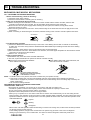
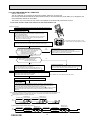
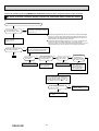
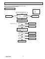
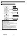
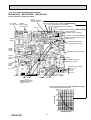
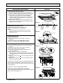
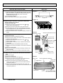
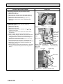
Revision B:
• MLZ-KA25/35/50VA- E3 have been
added.
SPLIT-TYPE AIR CONDITIONERS
Please void OBH483 REVISED EDITION-A.
INDOOR UNIT
No. OBH483
SERVICE MANUAL
REVISED EDITION-B
Models
MLZ-KA25VA
MLZ-KA25VA
MLZ-KA25VA
MLZ-KA35VA
MLZ-KA35VA
MLZ-KA35VA
-
E1
-
E2
-
E3
-
E1
-
E2
-
E3
MLZ-KA50VA
MLZ-KA50VA
MLZ-KA50VA
-
E1
-
E2
-
E3
Outdoor unit service manual
MXZ-A VA Series (OB377)
MXZ-B VA Series (OBH554)
MXZ-8B VA Series (OCH480)
MXZ-D VA Series (OBH626)
CONTENTS
MLZ-KA25VA
MLZ-KA35VA
MLZ-KA50VA
1. TECHNICAL CHANGES ··································· 2
2. PART NAMES AND FUNCTIONS ····················· 3
3. SPECIFICATION ················································ 4
4. NOISE CRITERIA CURVES ······························ 5
5. OUTLINES AND DIMENSIONS ························ 6
6. WIRING DIAGRAM············································ 7
7. REFRIGERANT SYSTEM DIAGRAM ············· 10
8. SERVICE FUNCTIONS ····································11
9. MICROPROCESSOR CONTROL ··················· 13
10. TROUBLESHOOTING ····································· 18
11. DISASSEMBLY INSTRUCTIONS ···················· 32
PARTS CATALOG (OBB483)
NOTE:
• RoHS compliant products have <G> mark on the spec name plate.
Revision A :
• MLZ-KA25/35/50VA- E2 have been added.
Revision B :
• MLZ-KA25/35/50VA- E3 have been added.
1
TECHNICAL CHANGES
MLZ-KA25VA- E1
MLZ-KA35VA- E1
MLZ-KA50VA- E1
MLZ-KA25VA- E2
MLZ-KA35VA- E2
MLZ-KA50VA- E2
1. Fan motor has been changed (RC0J30-KC
RC0J30-KK).
2. Control of auto fan speed has been changed. (When indoor units are connected with a multi type outdoor
unit, and operated in heat mode.)
Air flow in auto fan speed is changed depending on air outlet temperature of indoor unit.
3. Electronic control P.C. board has been changed.
MLZ-KA25VA- E2
MLZ-KA35VA- E2
MLZ-KA50VA- E2
MLZ-KA25VA- E3
MLZ-KA35VA- E3
MLZ-KA50VA- E3
1. Software has been changed for ERP.
OBH483B
2
2
PART NAMES AND FUNCTIONS
INDOOR UNIT
MLZ-KA25VA
MLZ-KA35VA
MLZ-KA50VA
Horizontal vane
Vertical vane
Air inlet
Air outlet
Intake grille
Air filter
(Catechin air filter, option)
Air cleaning filter
(Anti-Allergy Enzyme
Filter, option)
Display and operation section (When the intake grille is opened)
Remote control
receiving section
Operation indicator lamp
Emergency operation switch
Safety string
Remote controller
ACCESSORIES
MLZ-KA25VA
MLZ-KA35VA
MLZ-KA50VA
Alkaline battery (AAA) for remote controller
Drain hose (with insulation)
Special washer (with cushion, 4pcs)
Installation template
Fixing screw for
M5 х 30 mm
Band
Fixing screw for
4 х 16 mm
Remote controller
Remote controller holder
Fixing screw for 3.5 x 16 mm (Black)
OBH483B
3
2
1
8
1
4
1
2
1
1
2
3
SPECIFICATION
Indoor model
MLZ-KA25VA
MLZ-KA35VA
MLZ-KA50VA
Function
Heating
Cooling
Single phase
230V,50Hz
528/ 480/ 432
552/ 492/ 420
0.3
40
—
58
0.3
E1
RC0J30-KC
Heating
Cooling
Single phase
230V,50Hz
564/ 504/ 438
594/ 528/ 462
0.3
40
—
58
0.3
E1
RC0J30-KC
Heating
Cooling
Single phase
230V,50Hz
684/ 588/ 498
708/ 618/ 528
0.3
40
—
58
0.3
E1
RC0J30-KC
E2
E2
E2
Power supply
Capacity Air flow (High/Med./Low)
Running current 1
Power input 1
Auxiliary heater
Power factor 1
Fan motor current 1
Electrical
data
m3 /h
A
W
A(kW)
%
A
Fan motor Model
Special
remarks
E3
Dimensions W x H x D
mm
Weight
kg
Air direction
Sound level (High/Med./Low) dB(A)
Fan speed (High/Med./Low) rpm
Fan speed regulator
Remote controller model
RC0J30-KT
E3
RC0J30-KT
E3
1,102 x 175 x 360
1,102 x 175 x 360
1,102 x 175 x 360
15
15
15
5
5
5
36/ 32/ 28
38/ 35/ 31
43/ 39/ 34
35/ 32/ 29
37/ 34/ 31
43/ 38/ 34
1,120/1,030/950 1,160/ 1,060/ 930 1,180/ 1,080/ 960 1,230/ 1,120/ 1,000 1,380/1,220/1,070 1,420/ 1,270/ 1,120
3
3
3
KM07E
KM07E
KM07E
NOTE: Test conditions are based on ISO 5151.
Cooling: Indoor
Dry-bulb temperature 27°C Wet-bulb temperature 19°C
Outdoor Dry-bulb temperature 35°C Wet-bulb temperature 24°C
Heating: Indoor
Dry-bulb temperature 20°C
Outdoor Dry-bulb temperature 7°C Wet-bulb temperature 6°C
Refrigerant piping length (one way): 5m
1 Measured under rated operating frequency.
Specifications and rated conditions of main electric parts
Model
Item
Fuse
MLZ-KA25VA MLZ-KA35VA
(F11)
T3.15AL 250V
Horizontal vane motor
(MV1)
12V 300Ω
Vertical vane motor
(MV2)
12V 300Ω
(NR11)
ERZV14D471
Varistor
DRAIN PUMP
(DP)
230V 6.4W
FLOAT SENSOR
(FS)
DC 12V
OBH483B
RC0J30-KT
4
MLZ-KA50VA
4
NOISE CRITERIA CURVES
MLZ-KA25VA
MLZ-KA35VA
FAN SPEED FUNCTION
High
SPL(dB(A))
COOLING
35
HEATING
36
FAN SPEED FUNCTION
LINE
High
OCTAVE BAND SOUND PRESSURE LEVEL, dB re 0.0002 MICRO BAR
OCTAVE BAND SOUND PRESSURE LEVEL, dB re 0.0002 MICRO BAR
80
NC-70
60
NC-60
50
NC-50
40
NC-40
30
NC-30
20
10
APPROXIMATE
THRESHOLD OF
HEARING FOR
CONTINUOUS
NOISE
63
125
NC-20
250
500
1000
2000
4000
37
HEATING
38
LINE
Test conditions,
Cooling: Dry-bulb temperature 27ºC Wet-bulb temperature 19ºC
Heating: Dry-bulb temperature 20ºC
90
Test conditions,
Cooling: Dry-bulb temperature 27ºC Wet-bulb temperature 19ºC
Heating: Dry-bulb temperature 20ºC
90
70
SPL(dB(A))
COOLING
8000
80
70
NC-70
60
NC-60
50
NC-50
40
NC-40
30
NC-30
20
10
APPROXIMATE
THRESHOLD OF
HEARING FOR
CONTINUOUS
NOISE
63
125
NC-20
250
500
1000
2000
4000
8000
BAND CENTER FREQUENCIES, Hz
BAND CENTER FREQUENCIES, Hz
MLZ-KA50VA
FAN SPEED FUNCTION
High
SPL(dB(A))
COOLING
43
HEATING
43
LINE
OCTAVE BAND SOUND PRESSURE LEVEL, dB re 0.0002 MICRO BAR
Test conditions,
Cooling: Dry-bulb temperature 27ºC Wet-bulb temperature 19ºC
Heating: Dry-bulb temperature 20ºC
90
80
INDOOR UNIT
70
NC-70
CEILING
60
NC-60
1.4m
50
NC-50
40
MICROPHONE
NC-40
30
NC-30
20
10
APPROXIMATE
THRESHOLD OF
HEARING FOR
CONTINUOUS
NOISE
63
NC-20
125
250
500
1000
2000
4000
8000
BAND CENTER FREQUENCIES, Hz
OBH483B
5
GRILLE
5
OUTLINES AND DIMENSIONS
MLZ-KA25VA MLZ-KA35VA MLZ-KA50VA
INDOOR UNIT
Unit : mm
Center of ceiling opening, suspension bolt pitch
and grille are located in one position.
26
230
180
Drain hose
15
connecting part
1051 Suspension bolt pitch
Air outlet
(Front)
960
78
244
170
360
Drain hose
connecting
part (drain pipe
VP20)
110
16
Drain hose
1102
18
26
(51.6)
16
Electrical
box
58
158
2
2
Wireless
remote controller
308
Suspension bolt pitch
58
(Top)
(Right side)
Gas pipe
MLZ-KA25/35: Φ9.52
MLZ-KA50 : Φ12.7
(Flared)
Liquid pipe
Φ6.35
(Flared)
175
116
112
110
175
0.04m2
Grille (MLP-440W)
Drain pan
0
60
12
Outlet opening area
Pipe cover
48
13
0
Electrical box
Φ58
No gaps between
the ceiling surface and grille
1138
34
1200
Receiving section
CL
15
Liquid
R6
Refrigerant
Pipe
172.4
166.5
Gas
Φ6.35
Φ9.52 (MLZ-KA25/35)
Φ12.7 (MLZ-KA50)
Length of drain hose 540
Drain pipe
VP20
NOTE: Drain hose can be used by cutting it.
166.5
173
Hole position for the
installation of grille
Center of ceiling opening,
suspension bolt pitch and grille
are located in one position.
How to connect drain pipe on indoor
unit by lifting drain hose.
Drain hose can be used by cutting it.
Drain pipe VP20
Air outlet
500mm or less
Decline 1/100
Outlet
960
1051 Suspension bolt pitch
100
54.5
100
54.5
1160 Ceiling opening
20
20
1200 Outer side of grille
Suspension bolt M10
Suspension bolt M10
175
(Front)
Ceiling surface
OBH483B
Ceiling surface
Grille
6
(12)
308 Suspension bolt pitch
38
38
384 Ceiling opening
15
15
466.5
0
10
466.5
R6
(Top)
414 Outer side of grille
374
CL
0
414
81.8
180 or more
Ceiling
Display and surface
receiving section
(31)
Drain hose
6
WIRING DIAGRAM
INDOOR UNIT
MLZ-KA25VA- E1
MLZ-KA35VA- E1
MLZ-KA25VAMLZ-KA35VA-
E2
E2
OBH483B
7
MLZ-KA25VAMLZ-KA35VA-
MLZ-KA50VA-
E3
E3
E1
OBH483B
8
MLZ-KA50VA-
E2
MLZ-KA50VA-
E3
OBH483B
9
7
REFRIGERANT SYSTEM DIAGRAM
INDOOR UNIT
MLZ-KA25VA
MLZ-KA35VA
MLZ-KA50VA
Unit : mm
Refrigerant pipe Φ9.52
(with heat insulator)
Indoor
heat
exchanger
Indoor coil
thermistor
RT12 (main)
Refrigerant pipe Φ12.7
(with heat insulator)
Indoor
heat
exchanger
Flared connection
Indoor coil
thermistor
RT12,RT14,
RT15 (main)
Indoor coil
thermistor
RT13 (sub)
Indoor coil
thermistor
RT13 (sub)
Room temperature
thermistor
RT11
Room temperature
thermistor
RT11
Flared connection
Flared connection
Flared connection
Refrigerant pipe Φ6.35
(with heat insulator)
Refrigerant pipe Φ6.35
(with heat insulator)
Refrigerant flow in cooling
Refrigerant flow in heating
OBH483B
10
8
SERVICE FUNCTIONS
MLZ-KA25VA
MLZ-KA35VA
MLZ-KA50VA
8-1. TIMER SHORT MODE
For service, the following set time can be shortened by short circuit of JPG and JPS on the electronic control P.C. board.
(Refer to 10-7.)
Set time : 3-minute → 3-second (It takes 3 minutes for the compressor to start operation. However, the starting time is
shortened by short circuit-of JPG and JPS.)
8-2. P.C. BOARD MODIFICATION FOR INDIVIDUAL OPERATION
A maximum of 4 indoor units with wireless remote controllers can be used in a room.
In this case, to operate each indoor unit individually by each remote controller, both the P.C. boards of remote controller
and the electronic control P.C. boards must be modified according to the number of the indoor unit.
How to modify the remote controller P.C. board
Remove batteries before modification.
The board has a print as shown below:
NOTE: For modification, take out the batteries and press the OPERATE/
STOP (ON/OFF) button 2 or 3
times at first.
After modification, put back the
batteries then press the RESET
button.
J1
J2
The P.C. board has the print “J1” and “J2”. Solder “J1” and “J2” according to the number of indoor unit as shown in Table 1.
After modification, press the RESET button.
Table 1
1 unit operation
2 units operation
3 units operation
4 units operation
No. 1 unit
No modification
Same as at left
Same as at left
Same as at left
No. 2 unit
–
Solder J1
Same as at left
Same as at left
No. 3 unit
–
–
Solder J2
Same as at left
No. 4 unit
–
–
–
Solder both J1 and J2
How to modify the electronic control P.C. board
Turn OFF the power supply before modification. Cut off “JR05” and “JR06” on the electronic control P.C. board according
to the number of indoor unit as shown in Table 2. (Refer to 10-7.)
Table 2
JR05
JR06
No modification
No modification
No. 2 unit
Cut off JR05
No modification
No. 3 unit
No modification
Cut off JR06
No. 4 unit
Cut off JR05
Cut off JR06
No. 1 unit
Indoor electronic
control P.C. Board
Fuse (F11)
VARISTOR (NR11)
R111
JR05 JR06
IC101
C111T11
CN151
CN211
NOTE: After modification, turn ON the power supply and with the remote controller headed towards the indoor unit, press the
OPERATE/STOP (ON/OFF) button. If one or two beeps is heard from the indoor unit, modification is completed
correctly.
OBH483B
11
8-3. AUTO RESTART FUNCTION
When the indoor unit is controlled with the remote controller, the operation mode, the set temperature, and the fan speed
are memorized by the indoor electronic control P.C. board. “AUTO RESTART FUNCTION” automatically starts operation
in the same mode just before the shutoff of the main power.
Operation
If the main power has been cut, the operation settings remain.
After the power is restored, the unit restarts automatically according to the memory.
(However, it takes at least 3 minutes for the compressor to start running.)
How to disable “AUTO RESTART FUNCTION”
Turn off the main power for the unit.
Solder the Jumper wire to JR07 on the indoor electronic control P.C. board. (Refer to 10-7.)
F11
NOTE:
• The operation settings are memorized when 10 seconds have passed after
CN111 CN112 CN113 CN106
NR11
JR07
the indoor unit was operated with the remote controller.
• If main power is turned OFF or a power failure occurs while AUTO
IC101
START/STOP timer is active, the timer setting is cancelled.
• If the unit has been off with the remote controller before power failure, the
CN151
R111
C111
T11
CN211
auto restart function does not work as the power button of the remote controller is off.
• To prevent breaker tripping due to the rush of starting current, systematize
other home appliance not to turn on at the same time.
• When some air conditioners are connected to the same supply system, if
they are operated before power failure, the starting current of all the compressors may flow simultaneously at restart.
Therefore, the special counter-measures are required to prevent the main
voltage-drop or the rush of the starting current by adding to the system
that allows the units to start one by one.
8-4. P.C. BOARD MODIFICATION FOR CHANGING AIRFLOW VOLUME
Change dip switch SW3 setting according to the height of ceiling.
Dip switch SW3
Normal
Increase airflow volume
Ceiling height
2.4 m or below
above 2.4 m and 2.7 m or below
NOTE: When the ceiling is above 2.7 m, airflow volume may be insufficient even with the Dip switch (SW3)
set to "increase airflow.
How to change Dip switch (SW3) setting (Default setting is Normal)
1. Turn OFF the power supply for the air conditioner.
2. Remove electrical cover A and B.
3. Slide out electronic control P.C. board, and switch
up or down Dip switch (SW3).
4. Put electronic control P.C. board back to
the original position, and install electrical cover A and B.
NOTE:
To prevent damage of P.C. board due to static electricity,
make sure to perform static elimination before setting.
Electrical
cover A
Electronic control P.C. board
Electrical
cover B
Dip switch SW3
Normal
OBH483B
12
Increase
airflow volume
9
MICROPROCESSOR CONTROL
MLZ-KA25VA
MLZ-KA35VA
MLZ-KA50VA
WIRELESS REMOTE CONTROLLER
Signal transmitting section
Operation display section
OPERATE/STOP
(ON/OFF) button
Temperature buttons
Indication of
remote controller
model is on back
Open the front lid.
r
WIDE VANE button
FAN SPEED CONTROL button
OFF-TIMER button
OPERATION SELECT button
ECONO COOL button
ON-TIMER button
TIME SET buttons
FORWARD button
BACKWARD button
CLOCK SET button
RESET button
VANE CONTROL button
NOTE:
• The last setting will be stored after the unit is turned off with the remote controller.
• Indoor unit receives the signal of the remote controller with beeps.
OBH483B
13
INDOOR UNIT DISPLAY SECTION
Operation Indicator lamp
The operation indicator at the left side of the indoor unit indicates the operation state.
Operation state
Difference between target
temperature and
room temperature
This shows that the air conditioner is
operating to reach the target temperature.
Please wait until the target temperature is obtained.
Approximate
2ºC or more
Indication
Lighted
Blinking
This shows that the room temperature is
approaching the target temperature.
Approximate
2ºC or less
Not lighted
This shows a state of standby for operation.
(For multi system air conditioner)
9-1. COOL ( ) OPERATION
(1) Press OPERATE/STOP (ON/OFF) button.
OPERATION INDICATOR lamp of the indoor unit turns on with a beep tone.
(2) Select COOL mode with OPERATION SELECT button.
(3) Press TEMPERATURE buttons (TOO WARM or TOO COOL button) to select the desired temperature.
The setting range is 16 ~ 31°C.
1. Coil frost prevention
When the temperature of indoor heat exchanger becomes too low, the coil frost prevention mode works.
The indoor fan operates at the set speed and the compressor stops. This mode continues until the temperature of indoor
heat exchanger rises.
9-2. DRY ( ) OPERATION
(1) Press OPERATE/STOP (ON/OFF) button.
OPERATION INDICATOR lamp of the indoor unit turns on with a beep tone.
(2) Select DRY mode with OPERATION SELECT button.
(3) The set temperature is determined from the initial room temperature.
1. Coil frost prevention
Coil frost prevention is as same as COOL mode. (9-1.1.)
9-3. HEAT ( ) OPERATION
(1) Press OPERATE/STOP (ON/OFF) button.
OPERATION INDICATOR lamp of the indoor unit turns on with a beep tone.
(2) Select HEAT mode with OPERATION SELECT button.
(3) Press TEMPERATURE buttons (TOO WARM or TOO COOL button) to select the desired temperature.
The setting range is 16 ~ 31°C.
1. Cold air prevention control
When the compressor is not operating or is starting, and the temperature of indoor heat exchanger and/or the room
temperature is low or when defrosting is being done, the indoor fan will stop or rotate in Very Low speed.
9-4. AUTO CHANGE OVER ··· AUTO MODE OPERATION
Once desired temperature is set, unit operation is switched automatically between COOL and HEAT operation.
Mode selection
(1) Initial mode
When unit starts the operation with AUTO operation from off;
• If the room temperature is higher than the set temperature, operation starts in COOL mode.
• If the room temperature is equal to or lower than the set temperature, operation starts in HEAT mode.
(2) Mode change
COOL mode changes to HEAT mode when about 15 minutes have passed with the room temperature 2 degrees
below the set temperature.
HEAT mode changes to COOL mode when about 15 minutes have passed with the room temperature 2 degrees
above the set temperature.
NOTE:
If two or more indoor units are operating in multi system, there might be a case that the indoor unit, which is operating
in
(AUTO), cannot change over to the other operating mode (COOL
HEAT) and becomes a state of standby.
OBH483B
14
9-5. AUTO VANE OPERATION
1. Horizontal vane
(1) Vane motor drive
These models are equipped with a stepping motor for the horizontal vane. The rotating direction, speed, and angle of
the motor are controlled by pulse signals (approximately 12V) transmitted from indoor microprocessor.
(2) The horizontal vane angle and mode change as follows by pressing VANE CONTROL button.
1
2
3
4
5
(3) Positioning
To confirm the standard position, the vane moves until it touches the vane stopper. Then the vane is set to the desired
angle.
Confirming of standard position is performed in the following cases:
(a) When the power supply turns on.
(b) When the operation starts or finishes (including timer operation).
(c) When the test run starts.
(d) When multi-standby starts or finishes.
(e) When the swing operation finishes.
(4) VANE AUTO ( ) mode
In VANE AUTO mode, the microprocessor automatically determines the vane angle and operation to make the optimum
room-temperature distribution.
(1) In COOL and DRY operation
Vane angle is fixed to Angle 1.
(2) In HEAT operation
Vane angle is fixed to Angle 5.
1
5
(5) STOP (operation OFF) and ON-TIMER standby
In the following cases, the horizontal vane returns to the closed position.
(a) When OPERATE/STOP (ON/OFF) button is pressed (POWER OFF).
(b) When the operation is stopped by the emergency operation.
(c) When ON-TIMER is ON standby.
(6) SWING MODE ( )
By selecting SWING mode with VANE CONTROL button, the horizontal vane swings vertically. The remote controller
displays “ ”. SWING mode is cancelled when VANE CONTROL button is pressed once again.
(7) Cold air prevention in HEAT operation
The horizontal vane position is set to Upward.
(8) ECONO COOL ( ) operation (ECONOmical operation)
When ECONO COOL button is pressed in COOL mode, set temperature is automatically set 2°C higher.
Also the horizontal vane swings in various cycle.
SWING operation makes you feel cooler than set temperature. So, even though the set temperature is higher, the air
conditioner can keep comfort. As a result, energy can be saved.
To cancel this operation, select a different mode or press one of the following buttons in ECONO COOL operation:
ECONO COOL or VANE CONTROL button.
OBH483B
15
2. Vertical vane
(1) Press WIDE VANE button to change horizontal airflow direction.
•The vertical vane moves for about 30 seconds.
(After 30 seconds, the vertical vane moves to its original position. In this case, press WIDE VANE button again.)
(2) Press WIDE VANE button again to set horizontal airflow direction.
•The vertical vane stops and the airflow direction is set.
(3) Positioning
To confirm the standard position, the vane moves until it touches the vane stopper. Then the vane set to the desired
angle.
Confirming of standard position is performed in the following cases:
(a) When OPERATE/STOP (ON/OFF) button is pressed (POWER ON).
(b) When SWING is started.
9-6. DRAIN PUMP/ FLOAT SENSOR CONTROL
1. Drain pump
Operating condition:
1. During COOL, DRY, or emergency COOL operation
2. When float sensor detects water level above fixed point during:
(a) HEAT operation.
(b) emergency HEAT operation.
(c) standby when during multi system operation.
(d) standby when ON timer is set.
(e) operation STOP.
Drain pump operates in conditions 1 or 2.
Operation stop condition:
Condition other than 1 or 2 indicated above.
2. Float sensor
Float moves with the up and down of water surface inside the drain pan, and judges water level.
(Fixed point differs at raised and lowered water levels.)
Float sensor
Fixed point, when water level rises
Fixed point, when water level lowers
Water surface
9-7. TIMER OPERATION
1. How to set the time
(1) Press OPERATE/STOP (ON/OFF) button to start the air conditioner.
(2) Check that the current time is set correctly.
NOTE: Timer operation will not work without setting the current time. Initially “AM0:00” blinks at the current time display of
TIME MONITOR, so set the current time correctly with CLOCK SET button.
How to set the current time
(1) Press the CLOCK set button.
(2) Press the TIME SET buttons (
and
) to set the current time.
• Each time FORWARD button (
) is pressed, the set time increases by 1 minute, and each time BACKWARD button
(
) is pressed, the set time decreases by 1 minute.
• Pressing those buttons longer increases/decreases the set time by 10 minutes.
Press the CLOCK set button.
ON timer setting
) during operation.
(1) Press ON-TIMER button (
(2) Set the time of the timer using TIME SET buttons (
and
).
OFF timer setting
(1) Press OFF-TIMER button (
) during operation.
(2) Set the time of the timer using TIME SET buttons (
and
).
Each time FORWARD button (
) is pressed, the set time increases by 10 minutes; each time BACKWARD button
(
) is pressed, the set time decreases by 10 minutes.
OBH483B
16
2. Cancel
To cancel ON timer, press ON-TIMER button (
).
To cancel OFF timer, press OFF-TIMER button (
).
TIMER is cancelled and the display of set time disappears.
PROGRAM TIMER
• OFF timer and ON timer can be used in combination. The timer of the set time that is reached first will operate first.
• “ ” and “ ” display show the order of OFF timer and ON timer operation.
(Example 2) The current time is 11:00 AM.
(Example 1) The current time is 8:00 PM.
The unit turns OFF at 11:00 PM, and ON at 6:00 AM.
The unit turns ON at 5:00 PM, and OFF at 9:00 PM.
NOTE: If the main power is turned off or a power failure occurs while AUTO START/STOP timer is active, the timer setting
is cancelled. As these models are equipped with an auto restart function, the air conditioner starts operating with
timer cancelled when power is restored.
9-8. EMERGENCY/TEST OPERATION
In case of test run operation or emergency operation, use EMERGENCY OPERATION switch on the front of the indoor
unit. Emergency operation is available when the remote controller is missing, has failed or the batteries of the remote
controller run down. The unit will start and OPERATION INDICATOR lamp will light.
The first 30 minutes of operation is the test run operation. This operation is for servicing. The indoor fan runs at High
speed and the temperature control does not work.
After 30 minutes of test run operation, the system shifts to EMERGENCY COOL/HEAT MODE with a set temperature of
24°C. The fan speed shifts to Med.
The coil frost prevention works even in the test run or the emergency operation, and defrosting too.
In the test run or emergency operation, the horizontal vane operates in VANE AUTO ( ) mode.
Emergency operation continues until EMERGENCY OPERATION switch is pressed once or twice or the unit receives any
signal from the remote controller. In case of latter, normal operation will start.
NOTE: Do not press EMERGENCY OPERATION switch during normal operation.
Operation indicator lamp
EMERGENCY
OPERATION switch
Operation mode
Set temperature
Fan speed
Horizontal vane
COOL
24ºC
Medium
Auto
HEAT
24ºC
Medium
Auto
The operation mode is indicated by the Operation
indicator lamp on the indoor unit as following
Operation Indicator lamp
Press once <COOL>
Press again <HEAT>
Lighted
Not lighted
Press once again <STOP>
9-9. 3-MINUTE TIME DELAY OPERATION
When the system turns OFF, compressor will not restart for 3 minutes as 3-minute time delay function operates to protect
compressor from overload.
OBH483B
17
10
TROUBLESHOOTING
MLZ-KA25VA MLZ-KA35VA MLZ-KA50VA
10-1. CAUTIONS ON TROUBLESHOOTING
1. Before troubleshooting, check the following:
1) Check the power supply voltage.
2) Check the indoor/outdoor connecting wire for miswiring.
2. Take care of the following during servicing
1) Before servicing the air conditioner, be sure to turn off the unit first with the remote controller, and then after
confirming the horizontal vane is closed, turn off the breaker and/or disconnect the power plug.
2) Be sure to turn OFF the power supply before removing the front panel, the cabinet, the top panel, and the
electronic control P.C. board.
3) When removing the electronic control P.C. board, hold the edge of the board with care NOT to apply stress on the
components.
4) When connecting or disconnecting the connectors, hold the housing of the connector. DO NOT pull the lead wires.
<Incorrect>
<Correct>
Lead wiring
Housing point
3. Troubleshooting procedure
1) Check if the OPERATION INDICATOR lamp on the indoor unit is flashing ON and OFF to indicate an abnormality.
To make sure, check how many times the OPERATIONAL INDICATOR lamp is flashing ON and OFF before starting
service work.
2) Before servicing, check that the connector and terminal are connected properly.
3) When the electronic control P.C. board seems to be defective, check the copper foil pattern for disconnection and the
components for bursting and discoloration.
4) Refer to 10-2, 10-3 and 10-4.
4. How to replace batteries
Weak batteries may cause the remote controller malfunction.
In this case, replace the batteries to operate the remote controller normally.
Remove the front lid and insert batteries.
Press RESET button with a thin instrument, and
Then reattach the front lid.
then use the remote controller.
Insert the negative pole of the
batteries first. Check if the polarity
of the batteries is correct.
RESET button
NOTE: 1. If RESET button is not pressed, the remote controller may not operate correctly.
2. This remote controller has a circuit to automatically reset the microcomputer when batteries are replaced.
This function is equipped to prevent the microcomputer from malfunctioning due to the voltage drop caused by the
battery replacement.
3. Do not use the leaking batteries.
INFORMATION FOR MULTI SYSTEM AIR CONDITIONER
OUTDOOR UNIT : MXZ series
Multi system air conditioner can connect two or more indoor units with one outdoor unit.
•Unit will not operate in case the total capacity of indoor units exceeds the capacity of outdoor units.
Do not connect indoor units beyond the outdoor unit capacity.
Operation indicator lamp flashes as shown in the figure below.
•When you try to operate two or more indoor units with one outdoor unit simultaneously, one for the cooling and the
other for heating, the operation mode of the indoor unit that operates earlier is selected. The other indoor units cannot
operate and indicate as shown in the figure below. In this case, please set all the indoor units to the same operation mode.
OPERATION INDICATOR
Lighted
Blinking
Not lighted
•When indoor units start operation while the defrosting of outdoor unit is being done, it takes a few minutes (maximum
10 minutes) to blow out the warm air.
•In the heating operation, though indoor unit that does not operate may get warm or the sound of refrigerant
flowing may be heard, they are not malfunction. The reason is that the refrigerant continuously flows into it.
OBH483B
18
10-2. FAILURE MODE RECALL FUNCTION
Outline of the function
This air conditioner can memorize the abnormal condition which has occurred once.
Even though OPERATION INDICATOR lamp indication listed on the troubleshooting check table (10-4.) disappears, the
memorized failure details can be recalled.
This mode is very useful when the unit needs to be repaired for the abnormality which does not recur.
1. Flow chart of failure mode recall function for the indoor/outdoor unit
Operational procedure
The cause of abnormality cannot be found because the abnormality does not recur.
Setting up the failure mode recall function
Turn ON the power supply.
While pressing both OPERATION SELECT
button and TOO COOL button on the remote controller at the same
time, press RESET button.
First, release RESET button.
Hold down the other two buttons for another 3 seconds. Confirm that
the indicators on the LCD screen shown in the right figure are all
displayed. Then release the buttons.
1.Regardless of normal or abnormal, a short
beep is emitted once as the signal is received.
Press OPERATE/STOP (ON/OFF) button of the remote controller (the set temperature
is displayed) with the remote controller headed towards the indoor unit. 1
Does the left lamp of OPERATION INDICATOR lamp
on the indoor unit blink at the interval of 0.5 seconds?
Blinks: Either indoor or outdoor unit is abnormal.
Beep are emitted at the same timing
as the blinking of the left lamp of
OPERATION INDICATOR lamp. 2
Yes
(Blinks)
Judgment of indoor/outdoor abnormality
No
(OFF)
Before blinking, does the left lamp of OPERATION
INDICATOR lamp stay ON for 3 seconds?
Stays ON for 3 seconds (without beep):
The outdoor unit is abnormal.
Indoor unit is normal.
But the outdoor unit might be abnormal because there are some
abnormalities that are not memorized in the indoor unit.
Confirm if outdoor unit is abnormal according to the flow chart of the
detailed outdoor unit failure mode recall function.
Yes
No
The outdoor unit is abnormal.
Check the blinking pattern, and confirm the abnormal point with the
outdoor unit failure mode table (Refer to outdoor unit service manual).
Make sure to check at least two consecutive blinking cycles. 3
The indoor unit is abnormal.
Check the blinking pattern, and confirm the
abnormal point with the indoor unit failure mode table (10-2. 3.).
Make sure to check at least two consecutive blinking cycles. 2
Releasing the failure mode recall function
Release the failure mode recall function by the following procedures.
Turn OFF the power supply and turn it ON again.
Press RESET button of the remote controller.
As for outdoor unit, refer to outdoor unit service manual.
Repair the defective parts.
Deleting the memorized
abnormal condition
After repairing the unit, recall the failure mode again according to "Setting up the failure
mode recall function".
Press OPERATE/STOP (ON/OFF) button of the remote controller (the set temperature is
displayed) with the remote controller headed towards the indoor unit. 1
Press EMERGENCY OPERATION switch so that the memorized abnormal condition is deleted.
Release the failure mode recall function according to "Releasing the failure mode recall
function".
Note1.Make sure to release the failure mode recall function once it is set up, otherwise the unit cannot operate properly.
2.If the abnormal condition is not deleted from the memory, the last abnormal condition is kept memorized.
2. Blinking pattern when the indoor unit is abnormal:
Blinking at 0.52.5-second OFF second interval
Blinking at 0.52.5-second OFF second interval
ON
OFF
Beeps
Repeated cycle
Beeps
Repeated cycle
Beeps
Repeated cycle
3.Blinking pattern when the outdoor unit is abnormal:
Blinking at 0.52.5-second OFF
3-second ON
second interval
2.5-second OFF
3-second ON
Blinking at 0.5second interval
ON
OFF
No beep
Repeated cycle
OBH483B
Beeps
No beep
Repeated cycle
19
Beeps
Repeated cycle
2. Flow chart of the detailed outdoor unit failure mode recall function
Operational procedure
The outdoor unit might be abnormal.
Confirm if outdoor unit is abnormal according to the following procedures.
Confirm that the remote controller is in the failure mode recall
function.
1. Regardless of normal or abnormal, 2 short
beeps are emitted as the signal is received.
With the remote controller headed towards the indoor unit, press TOO COOL or TOO
WARM button to adjust the set temperature to 25ºC. 1
Does OPERATION INDICATOR lamp on the indoor
unit blink at the interval of 0.5 seconds?
Blinks: The outdoor unit is abnormal.
Beeps are emitted at the same timing as the
blinking of OPERATION INDICATOR lamp. 2
No
(OFF)
Yes
(Blinks)
The outdoor unit is abnormal.
Check the blinking pattern, and confirm the abnormal point with the
outdoor unit failure mode table (Refer to outdoor unit service manual).
Make sure to check at least two consecutive blinking cycles.
2
The outdoor unit is normal.
Releasing the failure mode recall function
Release the failure mode recall function by the following procedures.
Turn OFF the power supply and turn it ON again.
Press RESET button of the remote controller.
Release the failure mode recall function according
to the left mentioned procedure.
Repair the defective parts.
Deleting the memorized abnormal condition
After repairing the unit, recall the failure mode again according to
"Setting up the failure mode recall function".
Press OPERATE/STOP (ON/OFF) button of the remote controller (the set temperature is displayed)
with the remote controller headed towards the indoor unit.
Press EMERGENCY OPERATION switch so that the memorized abnormal condition is deleted.
Release the failure mode recall function according to "Releasing the failure mode recall function".
Note1. Make sure to release the failure mode recall function once it is set up, otherwise the unit cannot operate properly.
2. If the abnormal condition is not deleted from the memory, the last abnormal condition is kept memorized.
2.Blinking pattern when outdoor unit is abnormal:
2.5-second OFF
ON
OFF
3-second ON
No beep
Repeated cycle
OBH483B
Blinking at 0.5second interval
2.5-second OFF
3-second ON
No beep
Repeated cycle
Beeps
20
Blinking at 0.5second interval
Beeps
Repeated cycle
3. Indoor unit failure mode table
NOTE: Blinking patterns of this mode differs from the ones of Troubleshooting check table (10-4.).
Left lamp of
Right lamp of
OPERATION
OPERATION
INDICATOR lamp INDICATOR lamp
Not lighted
Not lighted
Abnormal point
(Failure mode)
Condition
Normal
Remedy
–
–
1-time flash
every 0.5-second
Not lighted
Room temperature
thermistor
When the room temperature thermistor
short or open circuit is detected every 8
seconds during operation.
2-time flash
2.5-second OFF
Not lighted
Indoor coil thermistor
(Main 1, 2 and sub)
[Main 2:MLZ-KA50VA]
When the indoor coil thermistor short or
open circuit is detected every 8 seconds
during operation.
3-time flash
2.5-second OFF
Not lighted
Serial signal error
When the serial signal from the outdoor unit is Refer to 10-6. "How to check miswiring
not received for a maximum of 6 minutes.
and serial signal error".
5-time flash
2.5-second OFF
Not lighted
Drain pump
Float sensor
Refer to the characteristics of the room
temperature thermistor (10-7.).
Refer to the characteristic of the main 1,2
indoor coil thermistor and the sub indoor
coil thermistor (10-7.).
• Float sensor is open.
• Float sensor detects abnormal water level.
• Check float sensor and drain pump.
• Check the connectors of float sensor
and drain pump.
• Refer to 10-6. "Check of float sensor".
11-time flash
2.5-second OFF
Not lighted
Indoor fan motor
When the rotational frequency feedback
signal is not emitted during 12-second the
indoor fan operation.
Refer to 10-6.
fan motor"
12-time flash
2.5-second OFF
Not lighted
Indoor control system
When it cannot properly read data in the
nonvolatile memory of the indoor electronic
control P.C. board.
Replace the indoor electronic control
P.C. board.
13-time flash
2.5-second OFF
Not lighted
Indoor coil thermistor
(Main 3)
[MLZ-KA50VA]
When the indoor coil thermistor short or
open circuit is detected every 8 seconds
during operation.
Refer to the characteristic of the main
3 indoor coil thermistor (10-7.).
OBH483B
21
"Check of indoor
10-3. INSTRUCTION OF TROUBLESHOOTING
Start
Indoor unit
operates.
Outdoor unit
does not
operate.
Outdoor unit
operates only
in Test Run
operation.
1
Check room
temperature
thermistor.
Refer to 10-7.
"TEST POINT
DIAGRAM AND
VOLTAGE".
Left lamp
Flash on and off
at 0.5-second
intervals
Cause:
Indoor/
Outdoor unit
• Mis-wiring
or trouble
of serial signal
Refer to 10-6.
"How to
check
miswiring
and serial
signal error
(when
outdoor unit
does not work)".
Indoor unit operates.
Outdoor unit does not
operate normally.
Outdoor unit
does not
operate
even in
Test Run
operation.
1
Unit does not
operate
normal
operation in
COOL or
HEAT mode.
Refer to
"How to check
inverter/
compressor".
Left lamp
2-time flash
Cause:
Indoor unit
• Trouble of
room temperature/
indoor coil
thermistor
Refer to
"Check of
R.V. coil".
Left lamp
3-time flash
Cause:
Indoor unit
• Trouble of
indoor fan
motor
Refer to 10-6.
Check room
"Check of
temperature
indoor fan
thermistor
motor".
and indoor
coil thermistor.
Refer to 10-7.
"Test point
diagram and
voltage".
OBH483B
Indoor unit
does not receive
the signal from
remote controller.
Indoor unit
operates, when
EMERGENCY
OPERATION
switch is pressed.
Refer to 10-6.
"Check of
remote controller,
display receiver
P.C. board and
indoor control
P.C. board".
Left lamp
4-time flash
Cause:
Indoor unit
• Trouble of
indoor unit
control
system
Replace the
indoor
electronic
control
P.C. board.
OPERATION INDICATOR
lamp on the indoor unit is
flashing on and off.
If blinking of OPERATION
INDICATOR lamp cannot be
checked, it can be checked with
failure mode recall function.
Indoor unit
does not operate,
when
EMERGENCY
OPERATION
switch is pressed.
1
"Test Run operation" means the
operation within 30 minutes after
EMERGENCY OPERATION switch
is pressed.
1. Check indoor/outdoor
connecting wire.
(Check if the power
is supplied to the
indoor unit.)
2. Refer to 10-6.
"Check of indoor
electronic control
P.C. board and indoor
fan motor".
Refer to outdoor unit service manual.
Left lamp
5-time flash
Cause:
Outdoor unit
• Outdoor
power
system
abnormality
Left lamp
6-time flash
Cause:
Outdoor unit
• Trouble of
thermistor
in outdoor
unit
Left lamp
7-time flash
Cause:
Outdoor unit
• Trouble of
outdoor
control
system
Left lamp
9-time flash
Cause:
Indoor unit
• Trouble of
float sensor
or drain
pump
Left lamp
14-time flash
Cause:
Outdoor unit
• Other
abnormality
• Check the
stop valve.
Refer to
"How to check
the inverter/
compressor".
Refer to
"Check of
outdoor
thermistors".
Replace the
inverter P.C.
board or
the outdoor
electronic
control P.C.
board.
Refer to 10-6. Check the
"Check of
drain pump.
float sensor".
Check
"Flow chart of
the detailed
outdoor unit
failure mode
recall function."
22
10-4. TROUBLESHOOTING CHECK TABLE
OPERATION INDICATOR
Lighted
Blinking
· Flashing of OPERATION INDICATOR lamp (left-hand side lamp) indicates
abnormalities.
Not lighted
NOTE: Before taking measures, make sure that the symptom reappears for accurate troubleshooting.
Self check table
No.
Abnormal
point
1
Miswiring
or serial
signal
Operation indicator lamp
Left lamp flashes.
0.5-second ON
Symptom
Condition
Remedy
Indoor unit
and outdoor
unit do not
operate.
When the serial signal from the outdoor unit is
not received for a maximum of 6 minutes.
• Refer to 10-6. "How to check
miswiring and serial signal
error".
0.5-second OFF
2
3
4
Outdoor
control
system
Left lamp lights up.
Indoor coil
thermistor
Left lamp flashes.
2-time flash
Room
temperature
thermistor
Indoor fan
motor
When it cannot properly read data in the
nonvolatile memory of the inverter P.C. board
or of the outdoor electronic control P.C. board.
• Check the blinking pattern of
the LED on the inverter P.C.
board or the outdoor
electronic control P.C. board.
When the indoor coil or the room temperature
thermistor is shorts or opens circuit.
• Refer to the characteristics of
indoor coil thermistor, and the
room temperature thermistor
on 10-7.
Indoor unit
and outdoor
unit do not
operate.
When the rotational frequency feedback
signal is not emitted during the indoor fan
operation.
• Refer to 10-6. "Check of
indoor fan motor".
Indoor unit
and outdoor
unit do not
operate.
When it cannot properly read data in the
nonvolatile memory of the indoor electronic
control P.C. board.
• Replace the indoor electronic
control P.C. board.
Indoor unit
and outdoor
unit do not
operate.
The compressor stops 3 times consecutively
for over current protection or start-up failure
protection within 1 minute after start-up.
Indoor unit
and outdoor
unit do not
operate.
When the outdoor thermistors short or open
circuit during the compressor operation.
Indoor unit
and outdoor
unit do not
operate.
When it cannot properly read data in the
nonvolatile memory of the inverter P.C. board
or of the outdoor electronic control P.C. board.
Outdoor unit
does not
operate.
Indoor unit
and outdoor
unit do not
operate.
2.5-second OFF
Left lamp flashes.
3-time flash
2.5-second OFF
5
Indoor
control
system
Left lamp flashes.
4-time flash
2.5-second OFF
6
Outdoor
power
system
Left lamp flashes.
5-time flash
2.5-second OFF
Left lamp flashes.
6-time flash
7
Outdoor
thermistors
2.5-second OFF
8
Outdoor
control
system
Left lamp flashes.
7-time flash
2.5-second OFF
9
Drain
pump
Left lamp flashes.
9-time flash
Indoor unit
and outdoor
unit do not
operate.
• Float sensor is open.
• Float sensor detects abnormal water level.
2.5-second OFF
10 Other
abnormality
Left lamp flashes.
14-time flash
2.5-second OFF
Indoor unit
and outdoor
unit do not
operate.
An abnormality other than above mentioned is
detected.
• Refer to "Check of inverter/
compressor".
Refer to outdoor unit service
manual.
Check the stop valve.
• Refer to "Check of outdoor
thermistor".
Refer to outdoor unit service
manual.
• Replace the inverter P.C.
board or the outdoor
electronic control P.C. board.
Refer to outdoor unit service
manual.
• Check float sensor
characteristics.
• Check drain pump.
• Check drain pipe.
• Check the connectors of float
sensor and drain pump.
• Refer to 10-6. "Check of float
sensor".
• Confirm the abnormality in
detail using the failure mode
recall function.
Refer to outdoor unit service
manual.
NOTE: When the indoor unit has started operation and the above failures are detected (the first detection after the power ON),
the indoor electronic control P.C. board turns OFF the indoor fan motor with OPERATION INDICATOR lamp flashing.
OBH483B
23
OPERATION INDICATOR
Lighted
Blinking
Not lighted
No.
Abnormal
point
1
MXZ type
Operation
mode
setting
· Flashing of OPERATION INDICATOR lamp (right-hand side lamp) indicates
abnormality.
· OPERATION INDICATOR lamp (left-hand side lamp) is lighted.
Operation indicator lamp
Right lamp flash
2.5-second OFF
Symptom
Condition
Outdoor unit
operates but
indoor unit
does not
operate.
When the operation mode of the each indoor
unit is differently set to COOL (includes DRY)
and HEAT at the same time, the operation
mode of the indoor unit that has operated at
first has the priority.
Remedy
• Unify the operation mode.
Refer to outdoor unit
service manual.
NOTE: When the indoor unit has started operation and the above failures are detected (the first detection after the power
ON), the indoor electronic control P.C. board turns OFF the indoor fan motor with OPERATION INDICATOR lamp
flashing.
10-5. TROUBLE JUDGEMENT CRITERIA OF MAIN PARTS
MLZ-KA25VA MLZ-KA35VA MLZ-KA50VA
Part name
Room temperature
thermistor (RT11)
Check method and criteria
Figure
Measure the resistance with a tester. (Part temperature 10°C ~ 30°C)
Normal
8 kΩ ~ 20 kΩ
Indoor coil thermistor
(RT12,RT14,RT15 (MAIN),
RT13 (SUB))
Indoor fan motor
Check 10-6.
.
Disconnect connector and check with a tester.
Check open or short according to the float position.
Float sensor
Float sensor
Float
position
Float sensor (FS)
Float
Float
Normal
Drain pump (DP)
Short
Open
Measure the resistance between the terminals with a tester.
(Part temperature 10ºC ~ 30ºC)
Horizontal vane
motor (MV1)
Vertical vane
motor (MV2)
OBH483B
Color of the lead wire
GRAY-GRAY
Normal
520Ω ~ 620Ω
Measure the resistance between the terminals with a tester.
(Part temperature 20ºC ~ 30ºC)
Color of the lead wire
BRN-other one
Normal
Each phase 380Ω
Measure the resistance between the terminals with a tester.
(Part temperature 20ºC ~ 30ºC)
Color of the lead wire
BRN-other one
Normal
Each phase 300Ω
24
RED
ROTOR
YLW
BRN
ORN
GRN
10-6. TROUBLESHOOTING FLOW
When the left lamp of OPERATION INDICATOR lamp flashes 3 times and the right lamp of OPERATION INDICATOR
lamp is not lighted.
Indoor fan does not operate.
A Check of indoor fan motor
The indoor fan motor error has occurred, and the indoor fan does not operate.
Pay careful attention to the high voltage on
the fan motor connector CN211.
Turn OFF the power supply.
Is there anything that interferes the
rotation of the line flow fan?
Turn ON the power supply, wait 5 seconds or more, and then press
EMERGENCY OPERATION switch.
Measure the supply voltage as follows within 12 seconds
after EMERGENCY OPERATION switch is pressed.
If more than 12 seconds passes by, turn OFF the power supply and
turn ON it again, then measure the voltage.
1) Measure the voltage between CN211 (+) and (-).
2) Measure the voltage between CN211 (+) and (-).
No
Yes
If more than 12 seconds passes after EMERGENCY OPERATION switch
is pressed, the voltage mentioned in above 2) goes 0V DC although the
indoor electronic control P.C. board is normal.
Remove the object and
adjust the line flow fan.
Is there 325V DC between
CN211 (+) and (-), and does
the voltage between CN211 (+)
and (-) rise to the range between 3
and 6V DC within 12 seconds after
EMERGENCY OPERATION switch
is pressed?
Yes
Indoor electronic
control P.C. Board
Replace the indoor fan motor.
Fuse (F11)
VARISTOR (NR11)
JR05 JR06
IC101
No
R111
C111T11
CN151
CN211
Replace the indoor electronic control P.C. board.
The indoor fan motor error has occurred, and the indoor fan repeats "12-second ON and 30-second OFF" 3 times, and then stops.
Measure the voltage between CN211
(+) and (-) while the fan
motor is rotating.
Is 0V DC or 15V DC
held unchanged?
Yes
(Unchanged)
Replace the indoor fan motor.
OBH483B
25
No
(Changed)
Replace the indoor electronic control P.C. board.
Indoor unit operates by pressing EMERGENCY OPERATION switch, but does not operate with the remote controller.
B
Check of remote controller, display receiver P.C. board and indoor control P.C. board
Check if the remote controller is exclusive for this air conditioner.
Press OPERATE/STOP (ON/OFF) button on the remote controller.
Is the display on the
remote controller visible?
No
(not clear)
Replace the batteries and press the
reset button on the remote controller.
(Refer to 10-1.4.)
Yes
1 Look at the signal transmitting section of the remote controller with a digital
camera or a camera phone. If the LED on the signal transmitting section is
illuminated when the OPERATE/STOP (ON/OFF) button on the remote controller is pressed, the remote controller is normal.
Press the reset button on the
remote controller.
(Refer to 10-1.4.)
Does the unit operate with
the remote controller?
2 If the inverter fluorescent light is turned on in a cool room, the signals transmitted by the remote controller will be barely or not at all received.
If the room is warm, even if the inverter fluorescent light is turned on, the signals transmitted by the remote controller may be received successfully.
No
Turn on the radio and set it to AM.
Press the OPERATE/STOP (ON/OFF)
button on the remote controller. 1
Yes
OK
Is noise heard
from radio?
Yes
No
Replace the remote controller.
Is any remote controller for other appliances
transmitting signals?
No
No
Is the air conditioner earthed?
Yes
Yes
Stop transmitting signals
from the remote controller(s)
for other appliance(s).
Is there any inverter
or rapid-start type
fluorescent light within
the range of 1 m? 2
Yes
Earth the air conditioner.
● Reinstall the air conditioner away from the
fluorescent light.
● Attach a glass filter on
the receiving part.
No
Press the OPERATE/STOP (ON/OFF) button on the remote controller, and measure
the voltage between CN301 (+) and (-)
on the display receiver P.C. board.
Is the voltage approximately
4 VDC to 5 VDC?
No
Replace the display receiver
P.C. board.
OBH483B
26
Yes
Replace the indoor electronic
control P.C. board.
The unit cannot be operated with the remote controller.
Also, OPERATION INDICATOR lamp does not light up by pressing EMERGENCY OPERATION switch.
C
Check of indoor electronic control P.C. board and indoor fan motor
Turn OFF the power supply.
Remove indoor fan motor connector CN211 and vane
motor connector CN151 from the indoor electronic
control P.C. board and turn ON the power supply.
Turn OFF the power supply.
Measure the resistance between CN211
and of the indoor fan motor connector.
Short/ open circuit:
Replace the indoor fan motor.
Yes
Does the unit operate with the remote controller?
Does OPERATION INDICATOR lamp light up by
pressing EMERGENCY OPERATION switch?
Turn OFF the power supply.
Measure the resistance of the horizontal vane
motor coil and the vertical vane motor coil.
Refer to 10-5.
Short/ open circuit:
Replace the horizontal vane motor, the vertical
vane motor coil and the indoor electronic
control P.C. board.
No
Replace the varistor (NR11) and fuse (F11).
Yes
Are the varistor (NR11) burnt No
and the fuse (F11) blown?
Turn OFF the power supply.
Check both “parts side” and “pattern
side” of the indoor electronic control P.C.
board visually.
Be sure to check both the fuse
and the varistor in any case.
Is the fuse (F11) blown only?
No
Yes
Measure the resistance between
(+) and (-) of the indoor fan
motor connector (to CN211 on the
indoor electronic control P.C. board).
1, 2
Is the resistance 1MΩ
or more?
1. The fan motor connector's
lead wire is red, whereas
is black.
2. Connect "+" of the tester to fan motor connector's lead
wire, and "-" to lead wire, otherwise the resistance cannot be
measured properly.
No
Replace the fuse (F11) and the indoor fan motor.
Yes
Replace the fuse (F11).
Is the resistance
approximately 4Ω?
Measure the cement resistance R111 on
the indoor electronic control P.C. board.
No
Yes
Indoor electronic
control P.C. Board
Fuse (F11)
VARISTOR (NR11)
R111
Replace the indoor electronic control P.C. board.
JR05 JR06
IC101
C111T11
CN151
CN211
OBH483B
27
Replace the indoor electronic control P.C. board
and the indoor fan motor.
When the left lamp of OPERATION INDICATOR lamp flashes ON and OFF in every 0.5-second.
Outdoor unit does not operate.
D How to check miswiring and serial signal error
Turn OFF the power supply.
Is there rated voltage of
230V AC in the power
supply?
No
Check the power
supply.
Yes
Turn ON the power supply.
Is there 230V AC between
outdoor terminal block S1 and
S2?
No
Check the wiring.
Yes
Press EMERGENCY OPERATION switch once.
Does the left lamp of OPERATION INDICATOR
lamp light up? <Confirmation of the power
supply to the indoor unit>
Yes
No
No
Is the serial signal error indicated 6 minutes later?
Yes
Is there any miswiring,
poor contact, or wire
disconnection of the
indoor/outdoor
connecting wire?
Yes
Correct them.
No
· Turn OFF inverter-controlled lighting equipment.
· Turn OFF the power supply and then turn it ON again.
· Press EMERGENCY OPERATION switch.
Is the serial
signal error
indicated 6
minutes later?
No
· Reinstall either the unit or the light away
from each other.
· Attach a filter on receiving section of the indoor unit.
Yes
Turn OFF the power supply.
Check once again if the indoor/outdoor
connecting wire is not wrongly connected.
Short-circuit the outdoor terminal block S2
and S3.
1
1. Miswiring may damage indoor electronic control
P.C. board during operation.
Be sure to confirm the wiring is correct before the
operation starts.
As for outdoor unit, refer to outdoor unit service manual.
OBH483B
28
When the left lamp of OPERATION INDICATOR lamp flashes 9-time.
Indoor unit and outdoor unit do not operate.
E Check of float sensor
Indoor electronic control P.C. board
Turn OFF the power supply and check
connectors CN145 and CN1N1 visually.
Yes
Connect the lead wire.
CN145
CN1N1
Are there abnormality in
the soldering part of
connectors?
Are the lead wires
disconnected?
Yes
Solder the connector.
No
No
Disconnect float sensor from CN145 of
indoor electronic control P.C. board.
Measure the resistance between and
*1 Refer to 10-5. when
float sensor can be checked.
Is the resistance 1Ω or
less? *1
Yes
.
Replace the indoor
electronic control P.C. board.
No
Is there large amount
of water in drain pan?
No
Replace the float sensor.
Yes
Turn ON the power supply. Press
EMERGENCY OPERATION switch
(COOL) and perform emergency COOL
operation. Measure the voltage between
CN1N1 and .
Is there 230V AC
between CN1N1 and
?
Yes
No
Is the drain pump
operating?
No
Replace the indoor
electronic control P.C. board.
Check power supply voltage.
Replace the drain pump.
Yes
Is the drain hose
clogged?
No
Replace the indoor
electronic control P.C. board.
OBH483B
29
Yes
Remove clog from drain
hose.
F Electromagnetic noise enters into TV sets or radios
Is the unit earthed?
No
Earth the unit.
Yes
Is the distance between the
antennas and the indoor
unit within 3m, or is the
distance between the
antennas and the outdoor
unit within 3m?
Yes
Extend the distance between
the antennas and the indoor
unit, or the antennas
and the outdoor unit.
No
Is the distance between the
TV sets or radios and the
indoor unit within 1m, or is
the distance between the TV
sets or radios and the
outdoor unit within 3m?
Yes
Extend the distance between
the TV sets or radios and the
indoor unit, or the TV
sets or radios and the
outdoor unit.
No
Are the antennas damaged?
Is the coaxial cable damaged?
Is there any poor contact in
the antenna wiring?
Yes
Replace or repair the antenna.
Replace or repair the coaxial cable.
No
Is the indoor/outdoor
connecting wire of the air
conditioner and the wiring of
the antennas in close?
Yes
Extend the distance between
the indoor/outdoor connecting
wire of the air conditioner and
the wiring of the antennas.
No
Even if all of the above conditions is fulfilled, the electromagnetic noise may enter, depending on
the electric field strength or the installation condition (combination of specific conditions such as
antennas or wiring).
Check the followings before asking for service.
1.Devices affected by the electromagnetic noise
TV sets, radios (FM/AM broadcast, shortwave)
2.Channel, frequency, broadcast station affected by the electromagnetic noise
3.Channel, frequency, broadcast station unaffected by the electromagnetic noise
4.Layout of ;
indoor/outdoor unit of the air conditioner, indoor/outdoor wiring, grounding wire, antennas, wiring
from antennas, receiver
5.Electric field intensity of the broadcast station affected by the electromagnetic noise
6.Presence or absence of amplifier such as booster
7.Operation condition of air conditioner when the electromagnetic noise enters in.
1)Turn OFF the power supply once, and then turn ON the power supply. In this situation check for
the electromagnetic noise.
2)Within 3 minutes after turning ON the power supply, press OPERATE/STOP (ON/OFF) button
on the remote controller for power ON, and check for the electromagnetic noise.
3)After a short time (3 minutes later after turning ON), the outdoor unit starts running. During
operation, check for the electromagnetic noise.
4)Press OPERATE/STOP (ON/OFF) button on the remote controller for power OFF, when the
outdoor unit stops but the indoor/outdoor communication still runs on. In this situation check for
the electromagnetic noise.
After checking the above, consult the service representative.
OBH483B
30
10-7. TEST POINT DIAGRAM AND VOLTAGE
MLZ-KA25VA
MLZ-KA35VA
MLZ-KA50VA
Indoor electronic control P.C. board
F11 FUSE
CN201
T3.15AL 250V Power supply
input 230V AC
CN111
Room temperature
thermistor RT11
CN112
Indoor coil thermistor RT14 (MAIN 2) [MLZ-KA50VA]
Indoor coil thermistor RT13 (SUB)
Indoor coil thermistor RT12 (MAIN 1)
CN113
5V DC
Indoor coil thermistor RT15 (MAIN 3) [MLZ-KA50VA]
Dip switch SW3
(Increase air flow volume)
To disable "Auto restart function",
solder the Jumper wire to JR07.
(Refer to 8-3.)
NR11
Varistor
short mode point
} Timer
JPG, JPS (Refer to 8-1.)
CN202
Serial
signal
Emergency operation switch
CN145
Float
sensor
CN151
Horizontal vane motor
Vertical vane motor
CN1N1
Drain
pump
Indoor fan motor CN211
over 15V DC
3-6V DC
15V DC
R111
325V DC
JR05 JR06
GND DC
12V DC
}
Modification point for
individual operation
(Refer to 8-2.)
Resistance (kΩ)
Indoor coil thermistor [RT12,RT14,RT15 (MAIN), RT13 (SUB)]
Room temperature thermistor (RT11)
Temperature (ºC)
OBH483B
31
11
DISASSEMBLY INSTRUCTIONS
<"Terminal with locking mechanism" Detaching points>
The terminal which has the locking mechanism can be detached as shown below.
There are two types ( Refer to (1) and (2)) of the terminal with locking mechanism.
The terminal without locking mechanism can be detached by pulling it out.
Check the shape of the terminal before detaching.
(1) Slide the sleeve and check if there is a locking lever or not.
Sleeve
Locking lever
(2) The terminal with this connector has the
locking mechanism.
Slide the sleeve.
Pull the terminal while
pushing the locking
lever.
Hold the sleeve, and
pull out the terminal
slowly.
Connector
MLZ-KA25VA MLZ-KA35VA MLZ-KA50VA
NOTE: Turn OFF power supply before disassembly.
PHOTOS
OPERATING PROCEDURE
1. Opening the intake grille
(1) Press the area indicated “PUSH” on the intake grille until a
click is heard (Figure 1).
(2) Hold the tabs on both sides of the intake grille and pull it
down.
Photo 1
Places for installing
the Anti-Allergy Enzyme filter (Option)
2. Removing the intake grille
(1) Press the area indicated “PUSH” on the intake grille until a
click is heard.
Hold the tabs on both sides of the intake grille and pull it
down (Figure 1).
(2) Pull the hinges of the intake grille toward you (Figure 2).
(3) Unhook the safety strings supporting the intake grille from
the front panel (Figure 3).
Remote
control
receiving
section
Electrical
box
Figure 1
Safety strings for
Places for installing
preventing the
intake grille from the air filters
(Catechin air filter, option)
falling
Intake grille
Figure 2
Figure 3
OBH483B
32
OPERATING PROCEDURE
PHOTOS
Figure 4
3. Checks before setting in place
(1) Before installing the grille, make sure the indoor unit is
square with the ceiling opening (or parallel to the wall-ceiling joint).
(2) Check that the four points for securing the grille are in
contact with the ceiling surface. Use the installation
template supplied with the indoor unit to arrange the four
points for securing the grille within 0 to 3 mm from the
ceiling surface (Figure 4, 5).
(3) Check that the insulation for the refrigerant pipes, drain
pipes, etc. are in place and that wiring connections and
arrangements are complete.
Close-up
Points for securing the grille
Points for securing the grille
Figure 5
Drain pan
Make sure
Ceiling surface that these
surfaces are
flush with
each other.
(0~3 mm)
4. Removing the horizontal vane
(1) Slide each stopper of the horizontal vane.
(2) Remove the horizontal vane (Figure 6).
NOTE:
To install, follow the removal procedure in reverse.
Make sure a click is heard from each stopper when
attaching the vane.
Places for
securing
the grille
Figure 6
Stopper
5. Removing the grille
(1) Open the intake grille.
(2) Remove the screw cap in the center of air outlet
(Figure 8).
(3) Remove the fixing screws ( and in Figure 7).
(4) Remove the temporary holding tabs of the grille.
6. Installing the grille
Horizontal vane
(1) Press the areas indicated “PUSH” on the intake grille
to open.
(2) Remove the screw cap in the center of air outlet.
(3) Open the horizontal vane completely.
(4) Hook the temporary holding tabs of the grille to the
indoor unit (Figure 7).
(5) Place the grille so that it fits properly in the
wall-ceiling joint, and attach the front panel with the fixing
screws provided. Do not fully tighten the screws at this
point.
(6) Tighten the fixing screws in the center three places and
(Figure 7).
(7) Tighten the fixing screws in the four places at left and
right side of the indoor unit.
Figure 7
Hooks
Temporary holding tabs
At this point, make sure there are no gaps between the indoor
unit and grille, and between the grille and ceiling surface. If
there are gaps, the wind may come in and it may cause water
to drip (Figure 9).
Screw cap
Tighten the fixing screw
and
completely.
Figure 8
Installing the Anti-Allergy Enzyme filter (Option)
Push the Anti-Allergy Enzyme filter into the guide of the grille
until a click is heard (Figure 10).
Screw cap
OBH483B
Make sure
that these
surfaces are
flush with
each other.
(0~3 mm)
33
OPERATING PROCEDURE
PHOTOS
7. Check after installing
(1) Check that there are no gaps between the indoor unit and
grille, and between the grille and ceiling surface (Figure 9).
(If there are gaps, the wind may come in and dew
condensation may result.)
(2) Is the air filter installed?
(3) Is the Anti-Allery Enzyme filter (Option) installed?
Figure 9
Indoor unit
Ceiling surface
No gaps here
Grille
Figure 10
8. Removing the electronic control P.C. board and
display receiver P.C. board
(1) Open the intake grille.
(2) Remove the screws for the electrical cover and .
Remove the covers (Photo 2).
(3) Remove the screw for the lamp cover and unhook it.
(4) Pull the electronic control P.C. board slightly toward you
from the electrical box, and disconnect all the connectors
from the electronic control P.C. board.
(5) Remove the electronic P.C. board and display receiver P.C.
board.
Anti-Allergy Enzyme filter (Option)
Photo 2
Screws for the electrical cover
Electrical cover
9. Removing the heat exchanger and nozzle
(1) Remove the grille.
(2) Remove the room temperature thermistor.
(3) Remove the two claws in the center of the nozzle and the
screws for the drain pan.
(4) Remove the screws for the electrical cover and .
Remove both covers.
(5) Disconnect the connectors of the vertical and horizontal
vane motor.
(6) Remove the indoor coil thermistor (main and sub.).
(7) Remove the screws for the drain cover. Remove the drain
cover.
(8) Remove the pipe band.
(9) Remove the screws for the heat exchanger. Remove the
heat exchanger.
(10) Remove the screws for the nozzle. Remove the nozzle.
Screw for the
electrical over
Electrical cover
Screw for the
lamp cover
Lamp cover
10. Removing the horizontal and vertical vane motor
unit
(1)
(2)
(3)
(4)
Remove the grille.
Remove the drain pan.
Remove the horizontal vane (Figure 6).
Remove the screws for the cover of the horizontal and
vertical vane motor unit. Remove the cover.
(5) Remove the screws for the vertical vane motor unit.
Remove the vertical vane motor unit and disconnect the
connectors (Photo 4).
(6) Remove the screws for the horizontal vane motor unit.
Remove the horizontal vane motor unit and disconnect the
connectors (Photo 4).
Drain pan
Photo 3
Drain cover
34
Room temperature thermistor
Indoor heat
exchanger
Float sensor
Drain pump
OBH483B
Screw for the
electrical cover
Nozzle
Cover of the horizontal
and vertical vane motor
OPERATING PROCEDURE
PHOTOS
Photo 4
11. Removing the drain pump and float sensor
(1)
(2)
(3)
(4)
(5)
(6)
(7)
Horizontal vane motor
Vertical vane motor
Remove the grille.
Remove the drain pan.
Disconnect the connector of the drain pump (Photo 5).
Disconnect the connector of the float sensor (Photo 5).
Remove the drain hose (Photo 5).
Remove the screws for the drain pump (Photo 5).
Remove the screws for the cover of the drain pump
(Photo 5).
12. Removing the fan motor and line flow fan
(1)
(2)
(3)
(4)
(5)
Remove the grille.
Remove the drain pan.
Remove the drain cover.
Remove the pipe band.
Remove the screws for the electrical cover and .
Remove both covers.
(6) Remove the screws for the terminal box. Remove the
terminal box.
(7) Untie the safety strings from the clamp (Photo 6).
(8) Hook the safety strings to the tab on the side of the heat
exchanger. (This prevents the heat exchanger from
falling.) Remove the screws for the heat exchanger and
pull the heat exchanger downward.
(9) Remove the screws for the nozzle. Remove the nozzle.
(10) Pull out the electronic control P.C. board slightly and
disconnect the connector (CN211) of the indoor fan motor.
(11) Remove the screws for the motor band. Remove the
motor band (Photo 6).
(12) Remove the indoor fan motor and line flow fan. (No need
to remove the heat exchanger before removing these 2
items.)
Nozzle
Photo 5
Drain hose
Float sensor
Cover of the
drain pump
Screws for
the drain
pump
Screws for
the cover
of the drain
pump
Drain pump
Screws for
the drain
pump
Screws for the Connector for
cover of the
the float sensor
drain pump
Photo 6
Fan motor
Connector for
the drain pump
Safety string
Motor band
Safety string
Line flow fan
OBH483B
35
Screws for the motor band
HEAD OFFICE: TOKYO BLDG., 2-7-3, MARUNOUCHI, CHIYODA-KU, TOKYO 100-8310, JAPAN
© Copyright 2012 MITSUBISHI ELECTRIC CORPORATION
Distributed in Nov. 2012 No. OBH483 REVISED EDITION-B
Distributed in Nov. 2009 No. OBH483 REVISED EDITION-A 7
Distributed in Feb. 2007 No. OBH483 8
Made in Japan
New publication, effective Nov. 2012
Specifications are subject to change without notice.