1
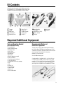
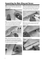
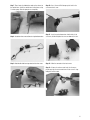
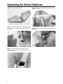
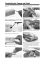
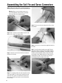
TM
TM
INSTRUCTION MANUAL
• Assembly time 3–5 hours
• Foam construction
• Stable, sporty flight characteristics
Specifications
Wingspan: . . . . . . . . . . . . . . . . . . . . . 33.25" (844.6 mm)
Overall Length. . . . . . . . . . . . . . . . . . . . 29" (736.6 mm)
Ready-To-Fly Weight. . . . . . . . 16–24 oz (436.6–680.4 g)
Radio (not included) . . . . . . . . . . . . 3-channel minimum
Battery Pack (not included) . . . . . . . . . . . . . . . . . . . . . .
. . . . . . . . . . . . . . . 8-cell 600mAh pack recommended
Speed Controller (included). . . . . . . . . . . . . . . . . . . . . .
. . . . . . . . . . . . . . . . . minimum 15-amp recommended
Table of Contents
Introduction . . . . . . . . . . . . . . . . . . . . . . . . . . . . . . . . . . . . 2
Assembly Tips . . . . . . . . . . . . . . . . . . . . . . . . . . . . . . . . . . . 2
Kit Contents . . . . . . . . . . . . . . . . . . . . . . . . . . . . . . . . . . . . 3
Required Additional Equipment . . . . . . . . . . . . . . . . . . . . . . 3
Assembling the Main Wing and Servos . . . . . . . . . . . . . . . . 4
Installing the Motor Mount . . . . . . . . . . . . . . . . . . . . . . . . . 7
Assembling the Vertical Stabilizers . . . . . . . . . . . . . . . . . . . . 8
Assembling the Canopy and Hatch . . . . . . . . . . . . . . . . . . . . 9
Assembling the Motor and Propeller . . . . . . . . . . . . . . . . . 10
Installing the Speed Controller and Delta Mixer . . . . . . . . . 11
Assembling the Tail Fin and Servo Connectors . . . . . . . . . . 12
Battery Charger . . . . . . . . . . . . . . . . . . . . . . . . . . . . . . . . . 13
Prior to First Flight . . . . . . . . . . . . . . . . . . . . . . . . . . . . . . 13
Flight Safety . . . . . . . . . . . . . . . . . . . . . . . . . . . . . . . . . . . 13
AMA Safety Code . . . . . . . . . . . . . . . . . . . . . . . . . . . . . . . 14
ElectraJet Spare Parts List . . . . . . . . . . . . . . . . . . . . . . . . . 15
Glossary of Terms . . . . . . . . . . . . . . . . . . . . . . . . . . . . . . . . 15
Introduction
Congratulations! You have purchased the E-Flite™ ElectraJet™,
a high-quality, electric ARF (Almost-Ready-To-Fly) R/C
park flyer.
If you are able to successfully fly a trainer-type R/C airplane
on your own, you should feel confident flying your electric
ElectraJet. Please take into consideration that smaller, lightweight park flyers like the ElectraJet fly best with no wind or
very light wind conditions.
If you are a first time R/C pilot, seek the guidance of an experienced R/C pilot before flying your ElectraJet. Flying with a more
experienced R/C flyer may prevent an unfortunate and untimely
loss of your airplane, as well as prevent possible injury to you
or spectators or damage to property.
The hobby shop where you purchased this kit may be able to
recommend a local R/C flying club that you could join. R/C
flying clubs often have very experienced R/C pilots who are
happy to provide guidance to less-experienced R/C pilots who
would like to develop flying skills. R/C flying clubs also have
dedicated R/C flying sites, which are best choices for flying
any type of R/C aircraft.
We hope your E-Flite ElectraJet brings you may hours of R/C
flying enjoyment. Thank you for purchasing this E-Flite product.
WARNING
An R/C aircraft is not a toy! If misused, it can cause serious
bodily harm and damage property. Fly only in open areas,
preferably AMA (Academy of Model Aeronautics) approved
flying sites. Follow all included instructions.
Assembly Tips
Carefully read assembly instructions and inspect all parts prior
to assembly.
In the assembly instructions, the left and right of the airplane
refer to the left and right side, as if you were stationed in the
cockpit.
Use 12-minute epoxy and silicone sealant for model assembly.
Moderate, but not excessive, amounts of adhesive are recommended. Remember to use what you need and no more. It is
important to keep park flyers light, adhesives add weight.
Build you model on a solid, flat surface in a well lit and well
ventilated location.
2
If you are an inexperienced builder, we recommend seeking the
guidance of a more experienced model builder to help you
assemble the kit.
If you encounter difficulty in any construction sequence, please
contact one of our technicians at
Horizon Hobby, Inc.
4105 Fieldstone Road
Champaign, IL 61822
(877) 504-0233
www.horizonhobby.com
Kit Contents
Carefully examine the contents of this kit before you start the
assembly process. It is recommended that you carefully read
through this instruction manual before you start assembly.
9
6
11
10
12
13
1
14
8
15
2
1
2
3
4
5
3
Fuselage
Canopy
Motor Cover
Left Wing Panel
Right Wing Panel
4
7
5
6
7
8
9
10
16
Vertical Fins (2)
Everons (2)
Hardware Package
Canopy hatch
Dorsal Fin
11 Speed Controller
(EFLA100)
12 Delta Mixer (EFLA101)
13 Motor + Gearbox
14 Prop Nut
15 Set Screw
16 Propeller
Required Additional Equipment
Tools and Supplies Needed
(not included in kit)
• Sharp hobby knife
• Double-sided servo tape
• Round file (small)
• Velcro® Tape
• Needle-nose pliers
• Masking tape
• Wire cutters
• Black felt-tipped pen or pencil
• Phillips screwdriver
• Flat-head screwdriver (medium)not included
• 1.5mm Allen wrench
• Sanding block with fine grit sandpaper
• Ruler
• Drill
• Drill Bit: 1/8"
• 12-minute epoxy
• Rubbing alcohol
• Odorless CA
• Clear silicone sealant
Recommended Radio and
Electronic Equipment
The best choice for your airborne radio equipment would be
the JR AirPac Micro (JRPF640), which combines two JR S241
Sub-Micro servos and one JR R610 6-channel FM micro receiver
into one package. Total weight for this three-piece
package is just over one ounce.
An 8-cell 600mAh battery pack
in kit)
A speed controller is included in the kit, as is the V-tail mixer
in the deluxe kit (EFLA1000). The best choice for your speed
controller is E-Flite 16-Amp Electric Speed Control (EFLA100).
If you do not have a radio that has delta mixing capabilities,
you can purchase a Delta Mixer for the standard kit (EFLA101).
3
Assembling the Main Wing and Servos
Step 1. Use a sanding block with fine sandpaper (preferably
400 grit) to remove the flashing from the areas that glue will be
applied on all foam parts. (Please read ahead to find out where
glue will be applied.)
Step 2. Trial fit the wings (both the left and right panel) onto the
fuselage. When you are satisfied with the fit, mix an adequate
amount of 12-minute epoxy and apply the epoxy to the wing
joiner slots (located on the fuselage) onto the main wings.
Step 3. Position the wing panels onto the fuselage and use
masking tape to hold the wing joints together while the epoxy
cures. Wipe off any excess epoxy using rubbing alcohol and a
paper towel. Make sure that the wing panels are perpendicular to
the fuselage. Please note that the masking tape may alter the finish slightly. Allow the epoxy to cure completely.
4
Step 4. Trial fit the hinges that will be placed into the wing for
the Elevons. Mix an adequate amount of 12-minute epoxy. Apply
to one side of the hinges on the horizontal wing. Use very small
amounts of epoxy when installing the hinges. If epoxy gets into
the hinge points, clean off the epoxy using rubbing alcohol.
Step 5. Apply small amounts of epoxy to the other side of the
hinges on the horizontal wing. Remember to keep the hinge
points clear of epoxy.
Step 6. Insert elevons onto wing.
Step 7. Please locate the indentations made on the elevons for
the control horns. Install the control horns to the elevons using
12-minute epoxy. Allow the epoxy to cure completely.
Step 10. Use a 2.0-mm drill bit to open up the holes in the
servo arm of each servo.
Step 8. Locate two micro servos and two sets of pushrod connectors.
Step 11. Insert the pushrod connectors into the holes in the
servo arms, but do not tighten the servo arm down at this time.
Step 9. Attach double-sided servo tape to each of the micro servos.
Step 12. Allow the connectors to be free to move.
Step 13. Using a wire cutter or metal snip, trim the excess
plastic away from the servo control arm on each servo. A sharp
hobby knife will also work.
5
Step 14. Remove the backing of the servo tape on the servos.
Step 17. Insert the other end of the Z-bent rod into the pushrod
connector. It will be helpful to use small pieces of masking tape to
hold the ailerons at the 0-degree deflection (centered on airfoil of
wing) while the control rods are being attached to the servo arms.
Step 15. Mount the servos and cables into each of the recesses
in the wings.
Step 18. With the servo arm centered and ailerons at neutral
(0 degrees deflection up or down), tighten the pushrod
connectors with the hex driver provided.
Step 16. Insert the Z-bent rod into each control horn of the
ailerons in the wing.
6
Installing the Motor Mount
Locate all motor mount parts as located in the picture below.
Step 1. Assemble the motor mount, but do not glue any of the
motor mount parts together!
Step 3. Apply epoxy to the motor mount recesses located in the
center of the fuselage and install the motor mount to the fuselage.
Step 4. Use masking tape to hold the motor mount in place on
the fuselage.
Step 2. Mix an adequate amount of 12-minute epoxy and apply
to the dowels.
7
Assembling the Vertical Stabilizers
Step 1. Locate the two vertical stabilizers.
Step 2. Mix an adequate amount of 12-minute epoxy and apply
to the recesses on the fuselage where the vertical stabilizers will
be mounted.
Step 3. Use a pin to hold the vertical stabilizers in place.
(Masking tape can also be used, but remember it can mark the
surface of the foam).
8
Step 4. The distance between the leading edge of the vertical
stabilizers is 215 mm.
Step 5. Wipe off any excess epoxy with rubbing alcohol and
paper towels.
Assembling the Canopy and Hatch
Step 1. Remove the flashing around the hatch with a sharp
hobby knife.
Step 2. Mix an adequate amount of 12-minute epoxy and apply
to the recess in hatch (which is located at the rear of the hatch)
and to one plywood square hold-down.
Step 5. Mix an adequate amount of 12-minute epoxy and coat
the underside on the plastic latch.
Step 6. Place the plastic latch onto the fuselage and glue in place.
Step 7. Using 12-minute epoxy, glue the hatch-latch recepticle
in place.
Step 3. Mount the plywood hold-down to the hatch.
Step 4. Assemble the plastic hatch latch.
Step 8. Locate the clear canopy from the kit contents. If needed,
trim the canopy to fit onto the hatch. Place a bead of odorless
CA around the canopy edge and place it onto the foam hatch as
seen in the picture below. If needed, hold the canopy in place
using masking tape.
9
Assembling the Motor and Propeller
Step 1. Locate the spinner, aluminum nut, set screw, and
propeller from the kit contents.
Step 2. When you insert the nut into the propeller, the printing
on the 8"x4" propeller must face toward the gearbox of the
motor when it is mounted to the motor.
Step 3. Use a propeller wrench to secure the spinner, aluminum
nut, and propeller to the propeller shaft.
10
Step 4. Use the 1.5 mm hex wrench to tighten the grub screw
of the aluminum nut to the propeller shaft of the motor/gearbox
(please note that the set screw will thread onto the flat spot on
the shaft).
Step 5. Secure the motor to the motor mount on the fuselage
with the four small rubber bands provided.
Step 6. Secure the cowling of the motor to the motor mount
with several small rubber bands.
Installing the Speed Controller and Delta Mixer
Step 1. Glue the Velcro® strip to one side of the fuselage.
This will be used to secure the battery in the fuselage.
Step 4. Pass the delta mixer wires out through the fuselage
onto the wing, as shown in the picture below.
Step 2. Locate the receiver, speed controller and delta mixer.
Please refer to the instructions provided with the speed controller
and delta mixer for an outline of the installation steps and
drawings of wiring and hook-up schematics.
STEP 5. With the receiver in the forward part of the fuselage,
pass the antenna through an opening in the fuselage in a similar
manner as the delta-mixer. Note that both the delta mixer and the
receiver are mounted forward of the battery in the fuselage.
Double-sided servo tape can be used to secure both to the fuselage.
Step 3. Before connecting the speed controller and delta-mixer,
use a sharp hobby knife to carve two small tunnels at the bottom
of the wing for the delta mixer connectors to slip between the
fuselage and the wing. Connect the delta mixer to the receiver
at this time. Temporarily position them in the forward part of
the fuselage.
Step 6. Place a piece of double-sided tape on the On/Off switch
and position it in the AFT part or the fuselage behind the battery.
11
Assembling the Tail Fin and Servo Connectors
Step 1. Make sure the power switch is off and that the battery is
not connected before you connect the motor and speed control plug.
Warning: Always assume the motor can come on at
any time. Be absolutely certain no power is connected
to the motor while you are working around it.
Step 5. Fix the servo wires to the wing with the 10 mm sticker
tape provided
Step 2. Now is the time to install the bottom vertical fin with
odorless CA, as shown in the picture below.
Step 6. Use the box as a reference when applying the decals to
the aircraft.
Step 3. Connect the servo leads to the delta-mix connectors
located near the fuselage.
Step 4. Fix the antenna cable on the main wing with the 10 mm
sticker tape provided. This sticker tape is located on the decal
sheet and is grey in color. This decal will have to be cut into
three strips as it will be used to cover the servo leads and the
receiver antenna.
12
Step 7. Check the center of gravity of your model. Place the
battery pack inside the fuselage so that the model will balance
properly. When the desired location is found, place the battery
inside the canard using double-sided servo tape. Please note
that the battery mounts between two pieces of foam which are
molded into the fuselage. These two pieces may have to be
trimmed depending on the battery of your choice.
Battery Charger
Refer to the instruction sheet provided with the charger.
CAUTION
It is important you read the instructions for proper
operation of the charger before you attempt charging the battery.
Failure to do so could result in injury or damage to property.
Prior to First Flight
Step 1. Ensure that all electronic and radio equipment is
properly installed and connected and that the battery is charged.
Step 4. Check for proper movement of the elevons and speed
controller. At a standard rate the control throws for the elevons
should be 1/4" up and 1/4" down.
Step 2. Make sure the motor is attached securely to the fuselage.
Step 3. Check the center of gravity. The center of gravity should
be located 8 1/2"–8 3/4" behind the leading edge of the wing.
Step 5. Range check your ElectraJet™ prior to the first flight
or the first flight after a repair. With the transmitter antenna
retracted, walk 30–40 paces from the model. With the assistance
of another person, check for the proper operation and movement
of the control surfaces and speed control.
Caution: Remember to keep your hands and face
clear of the propeller!
8 1/2"
Flight Safety
• Always take off and land into the wind.
• If you are an inexperienced R/C pilot, do not fly unless you
have an experienced R/C pilot with you.
• Never fly on or near a road with traffic. You may risk a
collision with an automobile or you may distract a driver,
which may cause an accident.
• Be sure to follow the AMA Safety Code on the following page.
• Fly only in open areas free of obstructions and never fly over
spectators. Your flying area should be clear of trees, buildings
and power lines.
13
AMA Safety Code
2001 Official AMA National Model Aircraft Safety Code Effective
January 1, 2001
Model flying must be in accordance with this code in order for
AMA liability protection to apply.
General
1. I will not fly my model aircraft in sanctioned events,
air shows, or model flying demonstrations until it has
been proven to be airworthy by having been previously,
successfully flight tested.
2. I will not fly my model higher than approximately 400 feet
within 3 miles of an airport without notifying the airport
operator. I will give right-of-way and avoid flying in the
proximity of full-scale aircraft. Where necessary, an observer
shall be utilized to supervise flying to avoid having models
fly in the proximity of full-scale aircraft.
3. Where established, I will abide by the safety rules for the flying
site I use, and I will not willfully and deliberately fly my
models in a careless, reckless, and/or dangerous manner.
4. At all flying sites, a straight or curved line(s) must be
established in front of which all flying takes place, with the
other side designated for spectators. Only personnel
involved with flying the aircraft are allowed in front of the
flight line. Flying over the spectator side of the line is
prohibited, unless beyond the control of the pilot(s). In any
case, the maximum permissible takeoff weight of the models
with fuel is 55 pounds.
5. At air shows or model flying demonstrations, a single
straight line must be established, one side of which is for
flying and the other side for spectators. Only those persons
accredited by the contest director or other appropriate official
as necessary for flight operations or as having duties or
functions relating to the conduct of the show or demonstration
are to be permitted on the flying side of the line. The only
exceptions which my be permitted to the single straight line
requirements, under special circumstances involving
consideration of side conditions and model size, weight,
speed, and power must be jointly approved by the AMA
President and the Executive Director.
6. Under all circumstances, if my model weighs over 20 pounds,
I will fly it in accordance with paragraph 5 of this section of
the AMA Safety Code.
7. I will not fly my model unless it is identified with my name
and address or AMA number, on or in the model. Note: This
does not apply to models while being flown indoors.
8. I will not operate models with metal-bladed propellers or
with gaseous boosts, in which gases other than air enter
their internal combustion engine(s); nor will I operate models
with extremely hazardous fuels such as those containing
tetranitromethane or hydrazine.
9. I will not operate models with pyrotechnics (any device that
explodes, burns, or propels a projectile of any kind) including,
but not limited to, rockets, explosive bombs dropped from
models, smoke bombs, all explosive gases (such as hydrogenfilled balloons), ground mounted devices launching a projectile.
The only exceptions permitted are rockets flown in accordance
14
with the National Model Rocketry Safety Code or those
permanently attached (as per JATO use); also those items
authorized for Air Show Team use as defined by AST Advisory
Committee (document available from AMA HQ). In any case,
models using rocket motors as primary means of propulsion
are limited to a maximum weight of 3.3 pounds and a G series
motor. Note: A model aircraft is defined as an aircraft with
or without engine, not able to carry a human being.
10. I will not operate any turbo jet engine (axial or centrifugal
flow) unless I have obtained a special waiver for such
specific operations from the AMA President and Executive
Director, and I will abide by any restriction(s) imposed for
such operation by them. (Note: This does not apply to
ducted fan models using piston engines or electric motors.)
11. I will not consume alcoholic beverages prior to, nor during,
participation in any model operations.
Radio Control
1. I will have completed a successful radio equipment ground
range check before the first flight of a new or repaired model.
2. I will not fly my model aircraft in the presence of spectators
until I become a qualified flier, unless assisted by an experienced helper.
3. I will perform my initial turn after takeoff away from the pit
or spectator areas, and I will not thereafter fly over pit or
spectator areas, unless beyond my control.
4. I will operate my model using only radio control frequencies
currently allowed by the Federal Communications Commission.
(Only properly licensed amateurs are authorized to operate
equipment on Amateur Band frequencies.)
5. I will not knowingly operate an R/C system within 3 miles
of a pre-existing model club-flying site without a frequency
sharing agreement with that club.
6. Models flown in air-to-air combat are limited to maximum
total engine displacement of .30 cubic inches and a maximum dry weight prior to flying of 4 pounds.
Organized RC Racing Event
7. An RC racing event, whether or not an AMA Rule Book
event, is one in which model aircraft compete in flight over a
prescribed course with the objective of finishing the course
faster to determine the winner.
In every organized racing event in which contestants, callers
and officials are on the course:
All officials, callers and contestants must properly wear
helmets which are OSHA, DOT, ANSI, SNELL or NOCASE
approved or comparable standard while on the race course;
All officials will be off the course except the starter and
his/her assistant.
“On the course” is defined to mean any area beyond the
pilot/staging area where actual flying takes place.
B. I will not fly my model aircraft in any organized racing event
which does not comply with paragraph A above or which
allows models over 20 pounds unless that competition event
is AMA sanctioned.
ElectraJet™ Spare Parts List
• Wing Replacement (EFL1001)
• Fuselage Replacement (EFL1002)
• Tail Replacement (EFL1003)
• Hardware Kit (EFL1004)
• Speed Controller (EFLA100)
• Delta Mixer (EFLA101)
• Propeller (EFLA300)
• Power Unit (EFLA400)
Glossary of Terms
Activating (Arming) Switch: An external switch that prevents
the electric motor from accidentally turning on.
Axis: A line passing through a body about which the body revolves.
Battery cycling: The repeated charge and discharge of a
battery to erase battery memory.
Battery Memory: Term used to explain why a battery is unable
to take on a full charge because of insufficient discharging
before recharging.
Capacity: The amount of charge or electricity a battery can hold.
Center of Gravity (CG): Balancing point of an aircraft.
Center Line: An imaginary line drawn through the center of the
aircraft from the nose through the tail.
Control Horn: The arm on the control surface that connects
with the pushrod.
Control Surface: The moveable parts on the wing and tail
that cause the aircraft to roll (ailerons), pitch (elevator),
or yaw (rudder).
Dihedral: The degree of angle (V-shaped bend) at which the
wing intersects the airplane is called dihedral. More dihedral
gives an airplane more aerodynamic stability. Some small
R/C airplanes and trainers with large dihedral dispense with
ailerons and use only the rudder to control roll and yaw.
Electrolyte: A caustic material found in batteries.
Elevator: The hinged control surfaces connected to the horizontal
stabilizer. The elevator controls the pitch of the airplane. On
a Mode II transmitter, pulling the right control stick back
makes the elevator move up and the airplane will nose up
and try to climb. Pushing the right control stick forward
moves the elevator down and causes the nose of the aircraft
to go down and the airplane to descend.
Fuselage: The main body of the airplane.
Harness: A device consisting of wires, switches, and a fuse that
connects the motor to the battery.
Horizontal Stabilizer: The horizontal surface of the tail that
provides stability in flight. The elevator is connected to the
horizontal stabilizer.
Leading Edge: The front edge of a flying surface (wing,
horizontal stabilizer, and vertical stabilizer).
Landing Gear: The wheel and gear assembly the airplane uses
to land. It is attached to the bottom of the fuselage or wings.
Nicad (Nickel Cadmium) battery: A rechargeable battery
used for radio control airplanes.
Pitch Axis: Degree of nose up or nose down from level to
the horizon.
Pushrod: The rigid wire that transfers movement from the
servo to the control surface
Receiver: The receiver unit in the airplane receives your
signals from the ground transmitter and passes the
instructions to the servos in the airplane.
Roll Axis: The horizontal plane on which the airplanes wingtips
are raised or lowered. The airplanes ailerons cause the airplane to roll left or right. On some smaller airplanes that do
not have ailerons, application of the rudder control, combined with the wing dihedral, will cause the airplane to roll.
Rudder: The control surface attached to the vertical stabilizer.
The rudder controls the yaw of the airplane (movement of
the nose of the aircraft left or right). Moving the left control
stick of the transmitter left or right causes the rudder to
move left or right.
Servo: The servo transforms your ground commands into
physical adjustments of a control surface while the airplane
is in flight.
Servo Arm: The moveable arm or wheel that connects the servo
to the pushrod (also called a servo horn).
Span: The maximum distance from wingtip to wingtip.
Speed Controller: An electronic device that functions as a
throttle for an electric motor. A speed controller controls
the speed or rpm of an electric motor.
Stall: Loss of lift resulting from exceeding the critical angle of
attack of the wing.
Transmitter: The device used on the ground to transmit
instructions to the airplane. Three transmitter modes are
used in model airplanes. The most common is Mode II
where the left stick controls the throttle and rudder and the
right stick controls the elevator and ailerons.
Vertical Stabilizer: One of the tail surfaces that provides
stability in flight. The rudder is connected to the vertical
stabilizer.
V-Tail: Combines the function of the elevator and ailerons into
one function, usually through an electronic mixer or through
a preset mix in the transmitter.
Wing: The wing provides the primary lifting force on an airplane.
Yaw Axis: The vertical plane through which the airplanes nose
passes as it yaws to the left or right. The rudder controls
movement around the yaw axis.
Z-Bend: The end of a pushrod wire with a “Z” shaped bend that
connects to the servo.
15
© Copyright 2001, Horizon Hobby, Inc.
www.horizonhobby.com