1
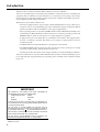
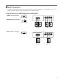
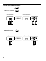
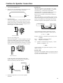
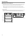
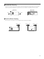
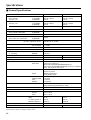
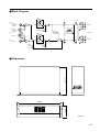
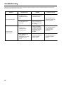
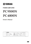
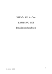
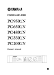
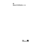
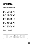
POWER AMPLIFIER
XS350
XS250
Owner’s Manual
350
POWER
POWER AMPLIFIER XS SERIES
ON
OFF
POWER
SIGNAL CLIP
CH A
PROTECTION
CLIP SIGNAL
CH B
E
Introduction
Thank you for purchasing a Yamaha XS350, XS250 series power amplifier.
This series of audio amps was developed from Yamaha's wealth of experience in building PA
equipment and its tradition of careful attention to every detail of circuit design. These amps
feature high power and superb quality together with superior reliability and stability, guaranteeing the highest possible audio performance.
Main features of the XS350, XS250 series
• The unit is equipped with two types of inputs: balanced XLR and barrier strip, and two types
of outputs: barrier strip and binding post. This combination of inputs and outputs affords
flexible capabilities and accommodates a wide range of applications.
• Three operating modes are provided: STEREO mode in which CHANNEL A and B operate
independently, PARALLEL mode in which a mono source is output by two amp systems, and
BRIDGE mode in which the unit operates as a single high-power amplifier.
• A high pass/low pass switchable filter is provided for each channel. The high pass filter
features a continuous controller that allows you to change cut-off frequencies between
25 Hz and 150 Hz.
• A SIGNAL indicator and CLIP indicator is provided for each channel.
• The PROTECTION indicator shows the status of protective circuitry such as power-on/off
protection, output muting, and the DC detection circuit.
• Variable-speed low-noise fan(s) ensures high reliability even under demanding conditions.
This owner's manual covers the two models XS350, XS250. In order to take full advantage of your
power amp and enjoy long and trouble-free operation, please read this owner's manual carefully
before use.
WARNING: THIS APPARATUS MUST BE EARTHED
IMPORTANT
THE WIRES IN THIS MAINS LEAD ARE COLOURED IN
ACCORDANCE WITH THE FOLLOWING CODE:
GREEN-AND-YELLOW :
EARTH
BLUE :
NEUTRAL
BROWN :
LIVE
As the colours of the wires in the mains lead of this apparatus may
not correspond with the coloured markings identifying the terminals in
your plug, proceed as follows:
The wire which is coloured GREEN and YELLOW must be
connected to the terminal in the plug which is marked by the letter E
or by the safety earth symbol
or coloured GREEN and YELLOW.
The wire which is coloured BLUE must be connected to the terminal
which is marked with the letter N or coloured BLACK.
The wire which is coloured BROWN must be connected to the
terminal which is marked with the letter L or coloured RED.
* This applies only to products distributed by YAMAHA KEMBLE
MUSIC (U.K.) LTD.
2
Precautions
•
•
•
•
•
•
•
•
•
Connect this unit’s power cord only to an AC outlet of
the type stated in this Owner’s Manual or as marked
on the unit. Failure to do so is a fire and electrical
shock hazard.
Do not allow water to enter this unit or allow the unit
to become wet. Fire or electrical shock may result.
Do not place heavy objects, including this unit, on top
of the power cord. A damaged power cord is a fire and
electrical shock hazard. In particular, be careful not to
place heavy objects on a power cord covered by a
carpet.
Do not scratch, bend, twist, pull, or heat the power
cord. A damaged power cord is a fire and electrical
shock hazard.
Do not remove the unit’s cover. You could receive an
electrical shock. If you think internal inspection,
maintenance, or repair is necessary, contact your
dealer.
Do not modify the unit. Doing so is a fire and electrical shock hazard.
If the power cord is damaged (i.e., cut or a bare wire is
exposed), ask your dealer for a replacement. Using the
unit with a damaged power cord is a fire and electrical
shock hazard.
If you notice any abnormality, such as smoke, odor, or
noise, or if a foreign object or liquid gets inside the
unit, turn it off immediately. Remove the power cord
from the AC outlet. Consult your dealer for repair.
Using the unit in this condition is a fire and electrical
shock hazard.
Should this unit be dropped or the cabinet be damaged,
turn the power switch off, remove the power plug from
the AC outlet, and contact your dealer. If you continue
using the unit without heeding this instruction, fire or
electrical shock may result.
•
•
•
•
•
•
•
•
•
•
Hold the power cord plug when disconnecting it from
an AC outlet. Never pull the cord. A damaged power
cord is a potential fire and electrical shock hazard.
Do not touch the power plug with wet hands. Doing so
is a potential electrical shock hazard.
This unit has ventilation holes at the front, rear and
sides to prevent the internal temperature rising too
high. Do not block them. Blocked ventilation holes are
a fire hazard.
Allow enough free space around the unit for normal
ventilation. This should be: 10 cm at the sides, 30 cm
behind, and 20 cm above.
These distances should also be adopted when rackmounting the unit. For normal ventilation during use,
remove the rear of the rack or open a ventilation hole.
If the airflow is not adequate, the unit will heat up
inside and may cause a fire.
To mount several of these units in an EIA-compliant
rack, refer to the rack mounting instructions on page
11.
Use only speaker cables when connecting speakers to
amplifier outputs. Using other types of cables is a fire
hazard.
Do not use this amplifier for any purpose other than
driving loudspeakers.
XLR-type connectors are wired as follows:
pin 1: ground, pin 2: hot (+), and pin 3: cold (–).
Using a mobile telephone near this unit may induce
noise. If noise occurs, use the telephone away from the
unit.
Clean the contacts of the phone plug before connecting
it to the SPEAKERS jack of this unit. Dirty contacts
may generate heat.
Contents
Controls and Functions ............................................. 4
Front Panel ........................................................... 4
Rear Panel ........................................................... 5
Speaker Impedance ............................................. 7
Caution for Speaker Connection ............................... 9
Rack Mounting ........................................................ 10
Mounting in an EIA standard rack ..................... 10
Portable Rack Mounting .................................... 11
Fixed Installation Mounting ................................ 11
General Specifications ....................................... 12
Specifications .......................................................... 12
Block Diagram .................................................... 13
Dimensions ........................................................ 13
Troubleshooting ...................................................... 14
3
Controls and Functions
■ Front Panel
POWER
1
3
2
ON
4
OFF
POWER
SIGNAL CLIP
CH A
1 POWER switch and indicator
This is the main POWER switch. Press to power ON
the amplifier. Press again to power OFF. The POWER
indicator lights up when the amplifier is powered ON.
2 SIGNAL indicators
These green LED indicators light up when the
respective channel’s output signal exceeds 2 Vrms.
This is equivalent to 1/2 W into 8Ω, 1 W into 4Ω.
3 CLIP indicators
These red LED indicators light up when the respective
channel’s output signal distortion exceeds 1% (i.e.
clipping). Output signal clipping is usually due to
excessive input signal levels.
PROTECTION
CLIP SIGNAL
CH B
4 PROTECTION indicator
These LED indicators light up to indicate that the
protection circuit is working. The speaker system is
disconnected from the amplifier outputs and no sound
is output from the speakers.
The protection circuit is activated in the following
situations:
• When the amplifier is powered on:
The protection circuit is activated for approximately 3
seconds when the amplifier is powered on. After 3
seconds, the protection system is deactivated automatically, and the amplifier is ready to use.
• If a DC voltage is present at the amplifier’s
outputs:
If the DC voltage problem is corrected, normal
amplifier operation resumes.
• If overheating occurs:
Turn off the power to the amplifier to cool down the
unit and consult the Precautions section of this manual
to improve the vent condition, if necessary. Turn the
power on to the amplifier after it cools down.
4
■ Rear Panel
1
2
3
4
FILTER
CHANNEL B
CHANNEL A
FREQ.
FREQ.
90
90
50
15
20
50
125
125
Hz
150
25
Hz
150
40
00
–dB
0
00
CHANNEL B
LOW CUT
SUB WOOFER
OFF
10
6
3
25
30
40
25
15
20
10
6
3
25
30
LOW CUT
SUB WOOFER
OFF
–dB
0
CHANNEL A
SPEAKERS
MODE
B-1
BRIDGE
STEREO
PARALLEL
B-2
CHANNEL
A-2
–
CHANNEL
A-1
4-8Ω/CHANNEL (STEREO)
+
+
–
4-8Ω/CHANNEL (STEREO)
+
+
–
–
INPUT
CHANNEL B
INPUT
CHANNEL A
CHANNEL B
G
CHANNEL A
(BRIDGE)
(PARALLEL)
G
(–)
(–)
(+)
(+)
8-16Ω (BRIDGE)
8-16Ω (BRIDGE)
(BRIDGE)
(PARALLEL)
5
6
1 Frequency controls/Filter select switches (CHANNEL A, B)
These knobs and sliding switches are used to select a
filter type and control the cut-off frequencies respectively. You can select one of the following filter type:
LOW CUT
SUB WOOFER
OFF
2 Volume controls (CHANNEL A, B)
These knobs enable you to adjust the output level of
Channels A and B in the range between –∞ dB and
0 dB. In BRIDGE mode, only the volume control for
Channel A is available.
3 STEREO/BRIDGE/PARALLEL switch
This slide switch is used to set the amplifier operating
mode: STEREO, BRIDGE or PARALLEL.
BRIDGE
STEREO
OFF ........................ Turns the filter off.
SUB WOOFER ...... Turns the low pass filter on.
(The cut-off frequencies for
the low pass filter are fixed.)
This setting is suitable when
using the unit as an amplifier
for a subwoofer.
LOW CUT .............. Turns the high pass (low cut)
filter on. (The cut-off frequencies are variable.)
If you select “LOW CUT,” you can use the frequency
controls to adjust the cut-off frequencies in the range
of 25 Hz to 150 Hz.
FREQ.
90
50
125
25
Hz
150
Note: In BRIDGE mode, only the frequency control
and filter select switch for Channel A are available.
PARALLEL
• STEREO mode
In this mode, channels A and B operate independently
(as a conventional stereo amp).
The CHANNEL A input signal will be output from
the CHANNEL A output jacks, and the CHANNEL B
input signal will be output from the CHANNEL B
output jacks.
• BRIDGE mode
In this mode, the CHANNEL A input signal will be
output from the BRIDGE output jacks. In this case,
use the rear panel CHANNEL A volume control to
adjust the volume.
• PARALLEL mode
In this mode, the CHANNEL A input signal will be
output from the output jacks of both channels A and
B. The CHANNEL B input jack is not used. The
CHANNEL A and B volumes can be adjusted
independently.
5
4 SPEAKERS terminals
6 GND terminals
Two types of speaker output terminals:
Binding post (Channel A-1, B-1) and barrier strip
(Channel A-2, B-2) are available.
These parallel wirings are internally connected and
output identical signals simultaneously. The output
impedance varies depending on whether you use
either or both types of SPEAKERS terminals. (Refer
to “Speaker Impedance” on page 7 for more information.)
The following figures show terminal polarity in
STEREO, PARALLEL, and BRIDGE modes.
• STEREO, PARALLEL mode
SPEAKERS
B-1
CHANNEL
A-1
4-8Ω/CHANNEL (STEREO)
B-2
CHANNEL
A-2
4-8Ω/CHANNEL (STEREO)
(–)
(–)
(+)
(+)
8-16Ω (BRIDGE)
8-16Ω (BRIDGE)
• BRIDGE mode
SPEAKERS
B-1
CHANNEL
A-1
4-8Ω/CHANNEL (STEREO)
B-2
CHANNEL
A-2
4-8Ω/CHANNEL (STEREO)
8-16Ω (BRIDGE)
8-16Ω (BRIDGE)
In BRIDGE mode, the (-) jacks of CHANNELS A1, B-1 and A-2, B-2 are not used.
The minimum impedance for the connected speaker
system is specified in “Speaker Impedance” on page 7.
5 INPUT terminals (CHANNEL A, B)
Two types of balanced terminals for channels A and B
are provided.
Channel A input terminal is used in BRIDGE and
PARALLEL mode.
• XLR-3-31 type connector
They are wired pin 1–ground, pin 2–hot (+), and pin 3
cold (-).
Hot
1
2
Ground
3
Cold
• Barrier strip
Hot (+), Cold (-) and Ground (G).
6
This is the grounding screw terminal. If hum or noise
occurs, ground (earth) the unit via this jack, or try
connecting it to the chassis of the mixer or preamp,
etc.
■ Speaker Impedance
In STEREO and PARALLEL modes, the minimum load (i.e., speaker) impedance is 4Ω. In BRIDGE mode it is 8Ω.
Make sure that the impedance does not fall below this specified impedance.
Using the barrier strip and binding posts simultanuously
STEREO mode connections:
MODE
SPEAKERS
BRIDGE
STEREO
PARALLEL
+
–
+
–
+
+
–
–
Set to STEREO
PARALLEL mode connections:
MODE
BRIDGE
STEREO
PARALLEL
– +
+ –
–
+
+
–
Set to PARALLEL
Each speaker
min. 8Ω
BRIDGE mode connections:
MODE
SPEAKERS
BRIDGE
STEREO
Each speaker
min. 8Ω
PARALLEL
+
–
+
–
+
+
–
–
Set to BRIDGE
–
+
Speaker
min. 16Ω
–
+
Speaker
min. 16Ω
7
Using the barrier strip or terminal posts
STEREO mode connections:
MODE
BRIDGE
STEREO
PARALLEL
Set to STEREO
PARALLEL mode connections:
MODE
BRIDGE
STEREO
PARALLEL
Set to PARALLEL
• Using the barrier strip
• Using the terminal posts
SPEAKERS
SPEAKERS
+
–
+
–
+
+
–
–
Not used
– +
+
–
–
+
+
+
–
–
Not used
+ –
–
+
Each speaker
min. 4Ω
+
–
Each speaker
min. 4Ω
BRIDGE mode connections:
MODE
BRIDGE
STEREO
PARALLEL
Set to BRIDGE
• Using the barrier strip
• Using the terminal posts
SPEAKERS
SPEAKERS
–
+
–
+
+
+
–
+
Speaker
min. 8Ω
8
+
–
–
Not used
–
–
+
+
+
–
–
Not used
–
+
Speaker
min. 8Ω
Caution for Speaker Connection
1. Turn off the POWER switch.
2. Remove the cover attachment screws and remove the
protective cover from the speaker terminals.
Screw
3. For Barrier strip:
After removing approx. 15 mm of insulation from the
ends of the speaker cables, bind the bare ends of the
speaker wires in the corresponding speaker terminals
and tighten the terminals to securely clamp the wires.
Refer to page 6 for speaker porality.
• Speaker fuse
The output capacity of your amplifier is very high:
170 W+170 W (8Ω), 250 W+250 W (4Ω) in stereo
and 500 W (8Ω) in monaural on the XS250;
230 W+230 W (8Ω), 350 W+350 W (4Ω) in stereo
and 700 W (8Ω) in monaural on the XS350.
Be sure to use a speaker system that has sufficient
input capacity.
If the input capacity of your speaker system is lower
than the rated output of the power amplifier, you can
protect your speakers by connecting a fuse serially
between the speaker and amplifier as shown below.
Speaker system
Power amplifier
_ +
+
_
15mm*
Fuse
Use the following formula to determine the fuse
capacity according to the speaker’s input capacity.
Po = I R → I = √Po/R
2
* Shown actual size.
For Five-way binding post:
After removing approx. 15 mm of insulation from the
ends of the speaker cables, pass the bare ends of the
speaker wires through the holes in the corresponding
speaker terminals and tighten the terminals to securely
clamp the wires. Refer to page 6 for speaker porality.
P0 [W] : Speaker’s continuous input capacity (noise
or RMS)
R [Ω] : Speaker’s nominal impedance
I [A] : Required fuse capacity
ex.)
Speaker’s continuous input capacity : 100 W
Speaker’s impedance : 8Ω
I = √100/8
15mm*
In this example, the required fuse capacity is calculated as 3.5 [A].
• Speaker cable
If you use a long speaker cable, use as thick a cable as
possible to prevent deterioration of the damping factor
or power loss inside the cable.
* Shown actual size.
At this time make sure that the bare ends of the
speaker cables do not extend from the terminals in
such a way that they touch the chassis.
Wire should not
touch the chassis.
Wire should not
touch the chassis.
4. Reattach the protective cover over the speaker
terminals.
9
Rack Mounting
■ Mounting in an EIA standard rack
If multiple high-power amp units are mounted in a rack with poor ventilation, the heat from the amps will cause the
interior of the amp to become very hot, causing the performance of the amps to be impaired. In particular, when
mounting in a rack whose back can not be left open, mount according to the following instructions.
Rack: Leave a gap of 10 cm or more between the rear panel of the rack and the rear panel of the amplifier.
Fan: Use a fan with 1.5 m3/min or more maximum wind and 5 mmH2O or more maximum static pressure.
Mounting: Install the fan kit on the top slot or the top panel of the rack and install a blanking panel between two
amps.
XS350/XS250
.5
ø4
4-
71.5±0.1
248
Blanking panel
5
6.
x
88
478
76.2
5
C1
78
Fan kit
71.5±0.1
Example of mounting
The figure on the left below shows an example of a fan kit (panels and two fans) on the top slot of the rack. The fans
are Minebia 3115PS-12T-B30 (with 0.9 m3/min maximum wind and 5 mmH2O maximum static pressure).
The figure on the right below is a dimensional diagram of a panel on which two 3115PS-12T-B30 are installed.
11
4-
463
480
XS350/XS250
Blanking panel
XS350/XS250
10
Unit: mm
■ Portable Rack Mounting
This unit uses a forced cooling system in which air comes in through the front opening and goes out from the sides
and rear. If you mount a single unit on a portable rack, be sure to maintain vent openings on the rear and sides.
(Side View)
(Rear View)
Completely open
Front
FILTER
CHANNEL B
CHANNEL A
LOW CUT
LOW CUT
40Hz
OFF
Air intake
Air exhaust
OFF
15
20
40Hz
80Hz
80Hz
40
10
6
3
25
30
40
00
HIGH CUT
5kHz
15
20
10
6
3
25
30
–dB
0
00
CHANNEL B
HIGH CUT
OFF
–dB
0
CHANNEL A
SPEAKERS
OUTPUT VOLTAGE
CHANNEL B
5kHz
10kHz
OFF
10kHz
70V
–
INPUT
CHANNEL B
CHANNEL A
CHANNEL A
100V
+
+
–
INPUT
CHANNEL B
+
–
G
+
CHANNEL A
–
G
70V = 32Ω/CHANNEL
100V = 64Ω/CHANNEL
■ Fixed Installation Mounting
Do not block the vent openings on the rear and sides when you use the power amplifier.
More than 10 cm
More than 10 cm
More than 10 cm
Front
Front
11
Specifications
■ General Specifications
XS250
Power Output Level (Rated Power)
20 Hz~20 kHz
THD+N= 0.1%
XS350
8Ω/STEREO
4Ω/STEREO
8Ω/BRIDGE
170 W + 170 W
250 W + 250 W
500 W
230 W + 230 W
350 W + 350 W
700 W
1 kHz
THD+N= 0.1%
8Ω/STEREO
4Ω/STEREO
8Ω/BRIDGE
185 W + 185 W
280 W + 280 W
560 W
250 W + 250 W
400 W + 400 W
800 W
1 kHz, 20 ms, no clip
600 W + 600 W
2Ω/STEREO
400 W + 400 W
Power Bandwidth
Half Power
10 Hz~40 kHz (THD+N= 0.1%)
Total Harmonic Distortion (THD + N)
20 Hz~20 kHz, Half Power
4~8Ω/STEREO
8Ω/BRIDGE
0.05%
Frequency Response
8Ω, Po= 1 W
+0.5, –1 dB
Intermodulation distortion (IMD)
60 Hz:7 kHz, 4:1, Half Power
4~8Ω/STEREO
8Ω/BRIDGE
0.05%
Channel Separation
Half Power, RL= 8Ω,
Vol. max., input 600Ω shunt
≥65 dB, 20 Hz~20 kHz
12.7 kHz LPF
IHF-A network
≤ –70 dB
≤ –75 dB
Damping Factor
8Ω, f= 1 kHz
≥100
Slew Rate
8Ω full swing
STEREO
BRIDGE
±30 V/µs
±40 V/µs
Residual Noise
Vol. min.
SN Ratio
10 Hz~50 kHz
100 dB
Sensitivity (Vol. max.) Rated Power into 8Ω
+1.7 dB
+3.1 dB
Voltage Gain (Vol. max.)
32.1 dB
32.1 dB
Input Impedance
30 kΩ/Balanced, 15 kΩ/Unbalanced
Controls
Front Panel
Rear Panel
POWER switch (ON/OFF)
Volume (31 position)x 2
Mode switch (STEREO/BRIDGE/PARALLEL)
Filter switch (OFF/SUBWOOFER/LOW CUT)x 2 (–12 dB/oct.)
Freq. control (25 Hz~125 Hz)x 2
Connectors
Input
Barrier strip terminal
XLR-3-31 type/ch
Barrier strip terminal
5-way binding posts
Output
Indicators
POWER
PROTECTION
CLIP
SIGNAL
Green
x 2 (Red)
x 2 (Red)
x 2 (Green)
Protection Circuits
POWER switch ON muting, DC detection,
Temp. detection (heatsink temp ≥ 90°C)
PC limiter
RL ≤ 1Ω
Fan Speed
Power Requirements
Low/~50°C, Variable/50~70°C, High/70°C~
US & Canada
Europe
Other
Power Consumption
Idling
1/8 output power, 4Ω
Maximum output, 4Ω
120 V, 60 Hz
230 V, 50 Hz
240 V, 50 Hz
450 W/600 VA
45 W
400 W
1000 W
Dimensions (W x H x D)
480 x 132 x 319 mm
Weight
18 kg
0 dB=0.775 Vrms, Half Power=1/2 Power Output Level (Rated Power)
Specifications subject to change without notice.
12
600 W/800 VA
45 W
550 W
1400 W
20 kg
■ Block Diagram
HPF
CHANNEL A
(BRIDGE)
(PARALLEL)
CLIP
FREQ
INPUT
CHANNEL A
(BRIDGE)
(PARALLEL)
SIGNAL
–
A-1
BA
LPF
CHANNEL A
+
+
–
+
PROTECTION
+
–
LOW CUT
SUB WOOFER
OFF
–
G
Protector
INV
INPUT
CHANNEL
B-1
SPEAKERS
+
HPF
–
G
INPUT
CHANNEL B
–
FREQ
CHANNEL B
A-2
LPF
+
+
–
+
CHANNEL
B-2
BA
CHANNEL B
LOW CUT
SUB WOOFER
OFF
PARALLEL
BRIDGE
STEREO
–
CLIP
SIGNAL
MODE
D:319
■ Dimensions
H:132
W:480
Unit: mm
13
Troubleshooting
The following table lists the main causes of abnormal operation and the corrective measures required, as well as the
protective circuit operation in each case.
Indicator
Probable Cause
Remedy
There is a short at a
speaker terminal,
amplifier terminal, or
wire.
Locate and correst the
cause of the short.
The amplifier load is
excessive.
Use a speaker system
with an impedance of
at least 4Ω (stereo) or
8Ω (bridge).
The heat sink
temperature has
exceeded 90°C.
Check the amplifier
ventilation conditions
and take appropriate
measures to improve
airflow around the
amplifier.
The thermal protection
circuit operates to
protect the power
transistors.
A DC voltage of ±2 V
or greater was
generated in the power
amplifier’s output
circuit.
Consult your dealer or
nearest Yamaha
service center.
The relay operates to
protect the speaker
system.
CLIP indicator lights.
PROTECTION
indicator lights.
14
Protection Circuit
The PC limiter circuit
operates to protect the
power transistors.
YAMAHA CORPORATION
V352950 R1 1 IP 16
NP Printed in Taiwan
Pro Audio Division, #18/3
P.O. Box 3, Hamamatsu, 430-8651, Japan