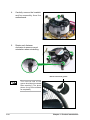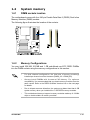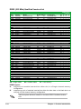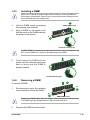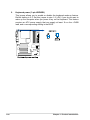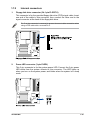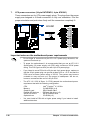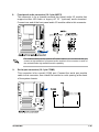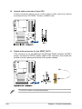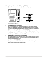
1
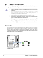
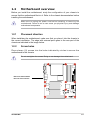
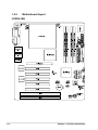
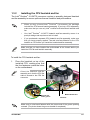
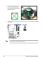
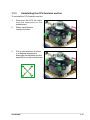
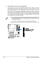
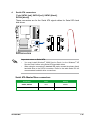
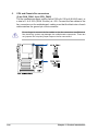
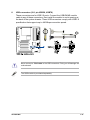
ATX i915GV-INA Series Intel® Pentium® 4 / Celeron® ATX Main Board User’s Manual Ver. 1.01 Contents Safety information ..........................................................................................v i915GV-INA specifications summary............................................................. vi Product introduction 1.1 Before you proceed ....................................................................... 1-2 1.2 Motherboard overview ................................................................... 1-3 1.3 1.4 1.5 ii 1.2.1 Placement direction ........................................................ 1-3 1.2.2 Screw holes .................................................................... 1-3 1.2.3 Motherboard layout......................................................... 1-4 1.2.4 Layout contents .............................................................. 1-5 Central Processing Unit (CPU) ...................................................... 1-6 1.3.1 Installing the CPU ........................................................... 1-6 1.3.2 Installing the CPU heatsink and fan ............................... 1-9 1.3.3 Uninstalling the CPU heatsink and fan ..........................1-11 System memory ............................................................................1-13 1.4.1 DIMM sockets location ..................................................1-13 1.4.2 Memory Configurations .................................................1-13 1.4.3 Installing a DIMM ...........................................................1-15 1.4.4 Removing a DIMM .........................................................1-15 Expansion slots.............................................................................1-16 1.5.1 Installing an expansion card ..........................................1-16 1.5.2 Configuring an expansion card......................................1-16 1.5.3 Interrupt assignments ....................................................1-17 1.5.4 PCI slots.........................................................................1-18 1.5.5 SDVO ADD2 slot ……....................................................1-18 1.6 Jumpers ........................................................................................1-19 1.7 Connectors .................................................................................. 1-21 1.7.1 Rear panel connectors ................................................. 1-21 1.7.2 Internal connectors ....................................................... 1-23 Contents BIOS setup 2.1 BIOS setup program ...................................................................... 2-2 2.2 BIOS menu screen ........................................................................ 2-3 2.3 Standard CMOS Features ............................................................. 2-5 2.4 Advanced BIOS Features .............................................................. 2-8 2.5 Integrated Peripherals ..................................................................2-10 2.6 Power Management Setup ...........................................................2-14 2.7 PC Health Status ..........................................................................2-16 2.8 Other items ...................................................................................2-17 2.8.1 Load Fail-Safe Defaults .................................................2-17 2.8.2 Load Optimized Defaults ...............................................2-17 2.8.3 Supervisor Password.....................................................2-17 2.8.4 User Password...............................................................2-17 2.8.5 Save & Exit Setup ..........................................................2-17 2.8.6 Exit Without Saving .......................................................2-17 Reversion History: 2008/07/11 Rev1.00 -> Rev1.01 Remove PCI Express Spec. change to SDVO Add2 Spec. Page 1,2,3,12,25,35 were changed. iii Notices Federal Communications Commission Statement This device complies with Part 15 of the FCC Rules. Operation is subject to the following two conditions: • This device may not cause harmful interference, and • This device must accept any interference received including interference that may cause undesired operation. This equipment has been tested and found to comply with the limits for a Class B digital device, pursuant to Part 15 of the FCC Rules. These limits are designed to provide reasonable protection against harmful interference in a residential installation. This equipment generates, uses and can radiate radio frequency energy and, if not installed and used in accordance with manufacturer’s instructions, may cause harmful interference to radio communications. However, there is no guarantee that interference will not occur in a particular installation. If this equipment does cause harmful interference to radio or television reception, which can be determined by turning the equipment off and on, the user is encouraged to try to correct the interference by one or more of the following measures: • Reorient or relocate the receiving antenna. • Increase the separation between the equipment and receiver. • Connect the equipment to an outlet on a circuit different from that to which the receiver is connected. • Consult the dealer or an experienced radio/TV technician for help. The use of shielded cables for connection of the monitor to the graphics card is required to assure compliance with FCC regulations. Changes or modifications to this unit not expressly approved by the party responsible for compliance could void the user’s authority to operate this equipment. C a n a d i a n D e p a r t m e n t o f C o m mu n i c a t i o n s Statement This digital apparatus does not exceed the Class B limits for radio noise emissions from digital apparatus set out in the Radio Interference Regulations of the Canadian Department of Communications. This class B digital apparatus complies with Canadian ICES-003. iv Safety information Electrical safety • To prevent electrical shock hazard, disconnect the power cable from the electrical outlet before relocating the system. • When adding or removing devices to or from the system, ensure that the power cables for the devices are unplugged before the signal cables are connected. If possible, disconnect all power cables from the existing system before you add a device. • Before connecting or removing signal cables from the motherboard, ensure that all power cables are unplugged. • Seek professional assistance before using an adapter or extension cord. These devices could interrupt the grounding circuit. • Make sure that your power supply is set to the correct voltage in your area. If you are not sure about the voltage of the electrical outlet you are using, contact your local power company. • If the power supply is broken, do not try to fix it by yourself. Contact a qualified service technician or your retailer. Operation safety • Before installing the motherboard and adding devices on it, carefully read all the manuals that came with the package. • Before using the product, make sure all cables are correctly connected and the power cables are not damaged. If you detect any damage, contact your dealer immediately. • To avoid short circuits, keep paper clips, screws, and staples away from connectors, slots, sockets and circuitry. • Avoid dust, humidity, and temperature extremes. Do not place the product in any area where it may become wet. • Place the product on a stable surface. • If you encounter technical problems with the product, contact a qualified service technician or your retailer. i915GV-INA specifications summary CPU LGA775 socket for Intel® Pentium® 4 / Celeron Processor Compatible with Intel® Mainstream/Value FMB process Supports Intel® Hyper-Threading Technology Chipset Northbridge: Intel® 915GV Graphics and Controller Hub (GMCH) Southbridge: Intel® ICH6 Front Side Bus (FSB) 800/533 MHz Memory 4 x 240-pin DIMM sockets support up to 4GB dual channel DDR2 400/533/667 MHz SDRAMs Expansion slots 1 x PCI-ExpressTM x16 slot for discrete graphics card 5 x PCI Slots 2 x ISA Slots Storage Intel® ICH6 Southbridge supports: - 2 x Ultra ATA 100/66/33 hard disk drives - 4 x Serial ATA hard disk drives Audio Realtek® ALC888GR 8CH high-definition Audio CODEC LAN Realtek® RTL 8110SC PCI Gigabit LAN controller VGA Intergrated Intel Graphics Media Accelerator 900 USB Supports up to 8 USB 2.0 ports BIOS Features 4MB FWH, Phoenix Award , Green, PnP, DMI2.3.4, ACPI 1.0, SM BIOS 2.3 Rear panel 1 x PS/2 mouse port 1 x Parallel port 2 x RJ-45 port 1 x Audio I/O 4 x USB 2.0 ports 1 x VGA port 1 x Serial port 1 x PS/2 keyboard port (continued on the next page) vi Internal connectors 1 x Floppy disk drive connector 1 x Primary IDE connector 4 x Serial ATA connectors 1 x CPU fan connector 2 x USB 2.0 connectors 1 x 24-pin ATX power connector 1 x 4-pin ATX 12V power connector 1 x Front panel audio connector 1 x Serial port connector 1 x Internal audio connectors 1 x S/PDIF Out connector 1 x Power LED connector 1 x System panel connector 1 x Chassis fan connector 1 x CD Audio in Power requirement ATX power supply (with 24-pin and 4-pin 12V plugs) Form Factor ATX form factor: 12 in x 9.6 in (30.5 cm x 24.5 cm) *Specifications are subject to change without notice. vii This chapter describes the motherboard features and the new technologies it supports. 1 Product introduction 1.1 Before you proceed Take note of the following precautions before you install motherboard components or change any motherboard settings. • Unplug the power cord from the wall socket before touching any component. • Use a grounded wrist strap or touch a safely grounded object or a metal object, such as the power supply case, before handling components to avoid damaging them due to static electricity • Hold components by the edges to avoid touching the ICs on them. • Whenever you uninstall any component, place it on a grounded antistatic pad or in the bag that came with the component. • Before you install or remove any component, ensure that the ATX power supply is switched off or the power cord is detached from the power supply. Failure to do so may cause severe damage to the motherboard, peripherals, and/or components. Onboard LED The motherboard comes with a standby power LED that lights up to indicate that the system is ON, in sleep mode, or in soft-off mode. This is a reminder that you should shut down the system and unplug the power cable before removing or plugging in any motherboard component. The illustration below shows the location of the onboard LED. 1-2 Chapter 1: Product introduction 1.2 Motherboard overview Before you install the motherboard, study the configuration of your chassis to ensure that the motherboard fits into it. Refer to the chassis documentation before installing the mothebroard. Make sure to unplug the power cord before installing or removing the motherboard. Failure to do so can cause you physical injury and damage motherboard components. 1.2.1 Placement direction When installaing the motherboard, make sure that you place it into the chassis in the correct orientation. The edge with external ports goes to the rear part of the chassis as indicated in the image below. 1.2.2 Screw holes Place eleven (11) screws into the holes indicated by circles to secure the motherboard to the chassis. Do not overtighten the screws! Doing so can damage the motherboard. Place this side towards the rear of the chassis i915GV-INA 1-3 1.2.3 Motherboard layout i915GV-INA 1-4 Chapter 1: Product introduction 1.2.4 Layout contents Slots 1. DDR2 DIMM slots Page 1-13 2. PCI slots 1-18 3. SDVO ADDE slot 1-18 Jumpers Page 1. Clear RTC RAM (CLRTC1) 1-19 2. Keyboard power (3-pin KBPWR1) 1-20 Rear panel connectors 1. PS/2 mouse port Page 1-21 2. Parallel port 1-21 3. LAN (RJ-45) port 1-21 4. Line In port 1-21 5. Line Out port 1-21 6. Microphone port 1-22 7. USB 2.0 ports 1-22 8. Video Graphics Adapter port 1-22 9. Serial port (COM1) 1-22 10. PS/2 keyboard port 1-22 Internal connectors 1. Floppy disk drive connector (34-1 pin FLOPPY1) Page 1-23 2. Power LED connector (3-pin PLED1) 1-23 3. Primary IDE connector (40-1 pin PRI_IDE1) 1-24 4. Serial ATA connectors (7-pin SATA1 [red], SATA2 [red], SATA3 [black], SATA4 [black]) 1-25 5. CPU and Chassis Fan connectors (3-pin CHA_FAN1, 4-pin CPU_FAN1) 1-26 6. USB connectors (10-1 pin USB56, USB78) 1-27 7. ATX power connectors (24-pin EATXPWR1, 4-pin ATX12V1) 1-28 8. Front panel audio connector (10-1 pin AAFP1) 1-29 9. Serial port connector (10-1 pin COM2) 1-29 10. Internal audio connectors (4-pin CD1) 1-30 11. Digital audio connector ((4-1 pin SPDIF_OUT1) 1-30 12. System panel connector (10-1 pin F_PANEL1) 1-31 i915GV-INA 1-5 1.3 Central Processing Unit (CPU) The motherboard comes with a surface mount LGA775 socket designed for the Intel® Pentium® 4 processor in the 775-land package. 1.3.1 • Your boxed Intel ® Pentium ® 4 LGA775 processor package should come with installation instructions for the CPU, heatsink, and the retention mechanism. If the instructions in this section do not match the CPU documentation, follow the latter. • Upon purchase of the motherboard, make sure that the PnP cap is on the socket and the socket contacts are not bent. Contact your retailer immediately if the PnP cap is missing, or if you see any damage to the PnP cap/socket contacts/motherboard components. Advansus will shoulder the cost of repair only if the damage is shipment/transit-related. • Keep the cap after installing the motherboard. Advansus will process Return Merchandise Authorization (RMA) requests only if the motherboard comes with the cap on the LGA775 socket. • The product warranty does not cover damage to the socket contacts resulting from incorrect CPU installation/removal, or misplacement/loss/ incorrect removal of the PnP cap. Installing the CPU To install a CPU: 1. Locate the CPU socket on the motherboard. Before installing the CPU, make sure that the socket box is facing towards you and the load lever is on your left. 1-6 Chapter 1: Product introduction 2. Press the load lever with your thumb (A), then move it to the left (B) until it is released from the retention tab. Retention tab A PnP cap Load lever B This side of the socket box should face you. To prevent damage to the socket pins, do not remove the PnP cap unless you are installing a CPU. 3. Lift the load lever in the direction of the arrow to a 135º angle. 4. Lif t the load plate with your thumb and forefinger to a 100º angle (A), then push the PnP cap from the load plate window to remove (B). B A Load plate 5. Position the CPU over the socket, making sure that the gold triangle is on the bottom-lef t corner of the socket. The socket alignment key should fit into the CPU notch. Alignment key Gold triangle mark i915GV-INA 1-7 6. Close the load plate (A), then push the load lever (B) until it snaps into the retention tab. A B The CPU fits in only one correct orientation. DO NOT force the CPU into the socket to prevent bending the connectors on the socket and damaging the CPU! Notes on Intel® Hyper-Threading Technology • This motherboard supports Intel ® Pentium ® 4 CPUs in the 775-land package with Hyper-Threading Technology. • Hyper-Threading Technology is supported under Windows ® XP/2003 Server and Linux 2.4.x (kernel) and later versions only. Under Linux, use the Hyper-Threading compiler to compile the code. If you are using any other operating systems, disable the Hyper-Threading Technology item in the BIOS to ensure system stability and performance. • Installing Windows® XP Service Pack 1 or later version is recommended. • Make sure to enable the Hyper-Threading Technology item in BIOS before installing a supported operating system. • For more information on Hyper-Threading Technology, visit www.intel. com/info/hyperthreading. To use the Hyper-Threading Technology on this motherboard: 1-8 1. Install an Intel® Pentium® 4 CPU that supports Hyper-Threading Technology. 2. Power up the system and enter the BIOS Setup (see Chapter 2: BIOS setup). Under the Advanced Menu, make sure that the item Hyper‑Threading Technology is set to Enabled. The item appears only if you installed a CPU that supports Hyper-Threading Technology. 3. Reboot the computer. Chapter 1: Product introduction 1.3.2 Installing the CPU heatsink and fan The Intel Pentium® 4 LGA775 processor requires a specially designed heatsink and fan assembly to ensure optimum thermal condition and performance. ® • When you buy a boxed Intel ® Pentium ® 4 processor, the package includes the CPU fan and heatsink assembly. If you buy a CPU separately, make sure that you use only Intel® ‑certified multi‑directional heatsink and fan. • Your Intel ® Pentium ® 4 LGA775 heatsink and fan assembly comes in a push-pin design and requires no tool to install. • If you purchased a separate CPU heatsink and fan assembly, make sure that you have properly applied Thermal Interface Material to the CPU heatsink or CPU before you install the heatsink and fan assembly. Make sure that you have installed the motherboard to the chassis before you install the CPU fan and heatsink assembly. To install the CPU heatsink and fan: 1. Place the heatsink on top of the installed CPU, making sure that the four fasteners match the holes on the motherboard. Or ient the heatsink and fan assembly such that the CPU fan cable is closest to the CPU fan connector. Narrow end of the groove Motherboard hole Fastener Make sure to orient each fastener with the narrow end of the groove pointing outward. (The photo shows the groove shaded for emphasis.) i915GV-INA 1-9 2. Push down two fasteners at a time in a diagonal sequence to secure the heatsink and fan assembly in place. B A A B 3. A B B A Connect the CPU fan cable to the connector on the motherboard labeled CPU_FAN1. Do not forget to connect the CPU fan connector! Hardware monitoring errors can occur if you fail to plug this connector. 1-10 Chapter 1: Product introduction 1.3.3 Uninstalling the CPU heatsink and fan To uninstall the CPU heatsink and fan: 1. Disconnect the CPU fan cable f r om t he c onnec tor on t he motherboard. 2. Rotate each fastener counterclockwise. 3. Pull up two fasteners at a time in a diagonal sequence to disengage the heatsink and fan assembly from the motherboard. B A A B i915GV-INA A B B A 1-11 4. Carefully remove the heatsink and fan assembly from the motherboard. 5. Rotate each fastener clockwise to ensure correct orientation when reinstalling. Narrow end of the groove The narrow end of the groove should point outward after resetting. (The photo shows the groove shaded for emphasis.) 1-12 Chapter 1: Product introduction 1.4 System memory 1.4.1 DIMM sockets location The motherboard comes with four 240-pin Double Data Rate 2 (DDR2) Dual Inline Memory Modules (DIMM) sockets. The following figure illustrates the location of the sockets: 1.4.2 Memory Configurations You may install 256 MB, 512 MB and 1 GB unbuffered non‑ECC DDR2 DIMMs into the DIMM sockets using the memory configurations in this section. i915GV-INA • For dual-channel configuration, the total size of memory module(s) installed per channel must be the same (DIMM_A2 = DIMM_B2). • A lways install DIM Ms with the same CAS latency. For optimum compatibility, it is recommended that you obtain memory modules from the same vendor. Refer to the DDR2 Qualified Vendors List on the next page for details. • Due to chipset resource allocation, the system may detect less than 4 GB system memory when you installed four 1 GB DDR2 memory modules. • This motherboard does not support memory modules made up of 128 Mb chips or double sided x16 memory modules. 1-13 DDR2 (533 MHz) Qualified Vendors List DIMM support (optional) Size Vendor Model Brand Side(s) Component CL A B C 512MB 1024MB 256MB 512MB 512MB 256MB 1024MB 512MB 512MB 512MB 256MB 512MB 256MB 512MB 1024MB 512MB 1024MB 512MB 1024MB 512MB 512MB 256MB 1024MB 512MB 256MB 512MB 1024MB 512MB 256MB 512MB 1024MB 256MB 512MB 1024MB 256MB 512MB 256MB 512MB 256MB 512MB 1024MB 256MB 512MB 512MB 512MB 1024MB SAMSUNG SAMSUNG SAMSUNG SAMSUNG Infineon Infineon Infineon Infineon CORSAIR MICRON MICRON MICRON Kingston Kingston Kingston Hynix Hynix Hynix Hynix ELPIDA ELPIDA KINGMAX KINGMAX KINGMAX KINGMAX KINGMAX KINGMAX TwinMOS Apacer Apacer Apacer NANYA NANYA NANYA elixir elixir crucial crucial CENTURY CENTURY CENTURY Aeneon Aeneon Aeneon Transcend Transcend M378T6553BG0-CD5 M378T2953BG0-CD5 M378T3253FG0-CD5 M378T6453FG0-CD5 HYS64T64000GU-3.7-A HYS64T32000HU-3.7-A HYS64T128020HU-3.7-A HYS64T64000HU-3.7-A CM2X512-4200 MT16HTF6464AG-53EB2 MT8HTF3264AY-53EB3 MT16HTF6464AY-53EB2 KVR533D2N4/256 KVR533D2N4/512 KVR533D2N4/1G HYMP564U648-C4 HYMP512U648-C4 HYMP564U64AP8-C3 HYMP512U64AP8-C3 EBE51UD8ABFA-5C EBE51UD8ABFA-5C-E KLBB68K-38SP4 KLBD48F-A8EP4 KLBC28F-A8EP4 KLBB68F-38KP4 KLBC28F-A8KP4 KLBD48F-A8KP4 8D-22JB5-K2T 78.81067.460 78.91066.420 78.01066.420 NT256T64UH4A0F-37B NT512T64U88A0F-37B NT1GT64U8HA0F-37B M2U25664TUH4A0F-37B M2U51264TU88A0F-37B BL3264AA53V.8FB BL6464AA53V.16FB 25V6S8SSD5F4-K43 25V2H8EL5CB4-J43 25V0H8EL5CB4-J45 AET560UD00-370A98X AET660UD00-370A98X AET660UD00-370A98X TS64MLQ64V5J TS128MLQ64V5J N/A N/A N/A N/A Infineon Infineon Infineon Infineon N/A MICRON MICRON MICRON ELPIDA N/A N/A N/A N/A N/A N/A ELPIDA ELPIDA N/A N/A N/A KINGMAX KINGMAX KINGMAX N/A N/A N/A N/A NANYA NANYA NANYA N/A N/A Ballistix Ballistix N/A N/A N/A Aeneon Aeneon Aeneon N/A N/A K4T51083QB-GCD5 K4T51083QB-GCD5 K4T56083QF-GCD5 K4T56083QF-GCD5 HYB18T512800AC37 HYB18T512160AF-3.7 HYB18T512800AF37 HYB18T512800AF37 N/A 4FBIID9BQM 4FBIID9CHM 4FBIID9CHM E5116AB-5C-E HY5PS56821F-C4 D6408TE7BL-37 HY5PS12821F-C4 HY5PS12821F-C4 HY5PS12821AFP-C3 HY5PS12821AFP-C3 E5108AB-5C-E E5108AB-5C-E K4T56083QF-GCD5 E5108AB-5C-E E5108AB-5C-E KKE388A4IA-37 KKEA88A4IA-37 KKEA88A4IA-37 K4T51083QB-GCD5 K4T56083QF-GCD5 E5108AB-5C-E E5108AB-5C-E NT5TU32M16AF-37B NT5TU64M8AF-37B NT5TU64M8AF-37B N2TU51216AF-37B N2TU51280AF-37B N/A N/A K4T56083QF-GCD5 E5108AB-5C-E E5108AB-5C-E AET960UD00-37C88X AET960UD00-37C88X AET93F-370AG0513 K4T51083QB-GCD5 K4T51083QB-GCD5 N/A 4 4 4 4 4 4 N/A 4 4 4 4 N/A N/A N/A 4 4 3 3 N/A N/A N/A N/A N/A N/A N/A N/A N/A 4 4 4 4 4 4 4 4 3 3 4 4 4 N/A N/A N/A 4 N/A V V V V V V V V V V V V V V V V V V V V V V V V V V V V V V V V V V V V V V V V V V V V V V V V V V V V V V V V V V V V V V V V V V V V V V V V V V V V V V V V V V V V V V V V V V V SS DS SS DS SS SS DS SS DS DS SS DS SS DS DS SS DS SS DS DS DS SS DS SS SS SS DS SS SS SS DS SS SS DS SS SS SS DS SS SS DS SS DS SS SS DS V V V V V V V V V V V V V V V V V V V V V V V V V V V V V V V V V V SS - Single-sided DS - Double-sided CL - CAS Latency DIMM support: A - suppor ts one module inser ted into either slot, in a Single-channel memor y configuration. B - supports one pair of modules inserted into either the blue slots or the black slots as one pair of Dual-channel memory configuration. Visit the system builder’s website for the latest DDR2 Qualified Vendors List. 1-14 Chapter 1: Product introduction 1.4.3 Installing a DIMM Make sure to unplug the power supply before adding or removing DIMMs or other system components. Failure to do so may cause severe damage to both the motherboard and the components. 2 1. Unlock a DIMM socket by pressing the retaining clips outward. 2. Align a DIMM on the socket such that the notch on the DIMM matches the break on the socket. DDR2 DIMM notch 1 1 Unlocked retaining clip A DDR2 DIMM is keyed with a notch so that it fits in only one direction. DO NOT force a DIMM into a socket to avoid damaging the DIMM. 3. Firmly inser t the DIMM into the socket until the retaining clips snap back in plac e and the DIM M is properly seated. Locked Retaining Clip 1.4.4 Removing a DIMM 2 To remove a DIMM: 1. Simultaneously press the retaining clips outward to unlock the DIMM. 1 1 DDR2 DIMM notch Support the DIMM lightly with your fingers when pressing the retaining clips. The DIMM might get damaged when it flips out with extra force. 2. Remove the DIMM from the socket. i915GV-INA 1-15 1.5 Expansion slots In the future, you may need to install expansion cards. The following sub‑sections describe the slots and the expansion cards that they support. Make sure to unplug the power cord before adding or removing expansion c ards. Failure to do so may c ause you physic al injur y and damage motherboard components. 1.5.1 Installing an expansion card To install an expansion card: 1. Before installing the expansion card, read the documentation that came with it and make the necessary hardware settings for the card. 2. Remove the system unit cover (if your motherboard is already installed in a chassis). 3. Remove the bracket opposite the slot that you intend to use. Keep the screw for later use. 4. Align the card connector with the slot and press firmly until the card is completely seated on the slot. 5. Secure the card to the chassis with the screw you removed earlier. 6. Replace the system cover. 1.5.2 Configuring an expansion card After installing the expansion card, configure the it by adjusting the software settings. 1-16 1. Turn on the system and change the necessary BIOS settings, if any. See Chapter 2 for information on BIOS setup. 2. Assign an IRQ to the card. Refer to the tables on the next page. 3. Install the software drivers for the expansion card. Chapter 1: Product introduction 1.5.3 Interrupt assignments Standard interrupt assignments IRQ Priority 0 1 2 3 4 5 6 7 8 9 10 11 12 13 14 15 1 2 11 12 13 14 15 3 4 5 6 7 8 9 10 Standard Function System Timer Keyboard Controller Re-direct to IRQ#9 Communications Port (COM2)* Communications Port (COM1)* IRQ holder for PCI steering* Floppy Disk Controller Printer Port (LPT1)* System CMOS/Real Time Clock IRQ holder for PCI steering* IRQ holder for PCI steering* IRQ holder for PCI steering* PS/2 Compatible Mouse Port* Numeric Data Processor Primary IDE Channel Secondary IDE Channel * These IRQs are usually available for ISA or PCI devices. IRQ assignments for this motherboard A PCI slot 1 PCI slot 2 Onboard USB controller 1 Onboard USB controller 2 Onboard USB controller 3 Onboard USB controller 4 Onboard USB 2.0 controller Onboard HDA Audio Onboard IDE Controller Onboard SATA Controller Onboard PCI LAN (1000 Mbps) Onboard IEEE 1394a controller B C D — — — — — — — — — — — shared — — — shared — — shared — used — — — — — — — — shared — — — — shared — — — shared — — shared — — — — — — E F G H — — — — — — — — — — — — shared — — — — — — — — — — shared — used — — — — — — — — — — — — — — — — shared — — — — — When using PCI cards on shared slots, ensure that the drivers support “Share IRQ” or that the cards do not need IRQ assignments; otherwise, conflicts will arise between the two PCI groups, making the system unstable and the card inoperable. i915GV-INA 1-17 1.5.4 PCI slots This motherboard has three PCI slots. The PCI slots suppor t cards such as a L AN c a r d, S C S I c a r d, U S B c a r d, a n d ot h e r cards that comply with PCI specifications. the figure shows a LAN card installed on a PCI slot. 1.5.5 SDVO Add2 slot This motherboard supports SDVO Add2 c a r d s t h a t c o m p l y w i t h the Intel SDVO specification. Be Award, it’s not PCI Express x 16 slot. 1-18 Chapter 1: Product introduction 1.6 1. Jumpers Clear RTC RAM (CLRTC1) This jumper allows you to clear the Real Time Clock (RTC) R AM in CMOS. You can clear the CMOS memory of date, time, and system setup parameters by erasing the CMOS RTC RAM data. The onboard button cell battery powers the RAM data in CMOS, which include system setup information such as system passwords. To erase the RTC RAM: 1. Turn OFF the computer and unplug the power cord. 2. Remove the onboard battery. 3. Move the jumper cap from pins 1-2 (default) to pins 2-3. Keep the cap on pins 2-3 for about 5~10 seconds, then move the cap back to pins 1-2. 4. Re-install the battery. 5. Plug the power cord and turn ON the computer. 6. Hold down the <Del> key during the boot process and enter BIOS setup to re-enter data. Except when clearing the RTC RAM, never remove the cap on CLRTC jumper default position. Removing the cap will cause system boot failure! i915GV-INA 1-19 2. Keyboard power (3-pin KBPWR1) This jumper allows you to enable or disable the keyboard wake-up feature. Default setting is 2-3. Set this jumper to pins 1-2 (+5V) if you do not want to wake up the computer when you press a key on the keyboard. This feature requires an ATX power supply that can supply at least 1A on the +5VSB lead, and a corresponding setting in the BIOS. 1-20 Chapter 1: Product introduction 1.7 Connectors 1.7.1 Rear panel connectors 1 2 3 4 5 6 10 9 7 8 1. PS/2 mouse port (green). This port is for a PS/2 mouse. 2. Parallel port. This 25-pin port connects a parallel printer, a scanner, or other devices. 3. LAN (RJ-45) port. This port allows Gigabit connection to a Local Area Network (LAN) through a network hub. Refer to the table below for the LAN port LED indications. The optional 10/100 Mbps LAN controller allows 10/100 Mbps connection to a Local Area Network (LAN) through a network hub. LAN port LED indications ACT/LINK LED SPEED LED Status Description Status Description OFF NO Link OFF 10Mbps connection GREEN Linked ORANGE 100Mbps connection BLINKING Data activity GREEN 1Gbps connection ACT/LINK SPEED LED LED LAN port 4. Line In port (light blue). This port connects a tape, CD, DVD player, or other audio sources. 5. Line Out port (lime). This port connects a headphone or a speaker. In 4-channel, 6-channel, and 8-channel configuration, the function of this port becomes Front Speaker Out. i915GV-INA 1-21 6. Microphone port (pink). This port connects a microphone. 7. USB 2.0 ports. These four 4-pin Universal Serial Bus (USB) ports are available for connecting USB 2.0 devices. 8. Video Graphics Adapter port. This 15-pin port is for a VGA monitor or other VGA-compatible devices. 9. Serial port. This 9-pin COM1 port is for pointing devices or other serial devices. 10. PS/2 keyboard port (purple). This port is for a PS/2 keyboard. 1-22 Chapter 1: Product introduction 1.7.2 1. Internal connectors Floppy disk drive connector (34-1 pin FLOPPY1) This connector is for the provided floppy disk drive (FDD) signal cable. Insert one end of the cable to this connector, then connect the other end to the signal connector at the back of the floppy disk drive. Pin 5 on the connector is removed to prevent incorrect cable connection when using a FDD cable with a covered Pin 5. 2. Power LED connector (3-pin PLED1) This 3-pin connector is for the system power LED. Connect the 3‑pin power LED cable from the system chassis to this connector. The LED lights up when you turn on the system power, and blinks when the system is in sleep mode. i915GV-INA 1-23 3. Primary IDE connector (40-1 pin PRI_IDE1) This connector is for an Ultra DMA 10 0/6 6 signal cable. The Ultra DMA 100/66 signal cable has three connectors: a blue connector for the primary IDE connector on the motherboard, a black connector for an Ultra DMA 100/66 IDE slave device (optical drive/hard disk drive), and a gray connector for an Ultra DMA 100/66 IDE master device (hard disk drive). If you install two hard disk drives, you must configure the second drive as a slave device by setting its jumper accordingly. Refer to the hard disk documentation for the jumper settings. 1-24 • Pin 20 on the IDE connector is removed to match the covered hole on the Ultra DMA cable connector. This prevents incorrect insertion when you connect the IDE cable. • Use the 80-conductor IDE cable for Ultra DMA 100/66 IDE devices. Chapter 1: Product introduction 4. Serial ATA connectors (7-pin SATA1 [red], SATA2 [red], SATA3 [black], SATA4 [black]) These connectors are for the Serial ATA signal cables for Serial ATA hard disk drives. Important notes on Serial ATA • You must install Windows ® 2000 Service Pack 4 or the Windows ® XP Service Pack1 before using Serial ATA hard disk drives. • When using the connectors in standard IDE mode, connect the primary (boot) hard disk drive to the SATA1 connector. Refer to the table below for the recommended hard disk drive connections. Serial ATA Master/Slave connectors i915GV-INA Connector Color Setting SATA1, SATA2 Red Master SATA3, SATA4 Black Slave 1-25 5. CPU and Chassis Fan connectors (3-pin CHA_FAN1, 4-pin CPU_FAN1) The fan connectors support cooling fans of 350 mA~740 mA (8.88 W max.) or a total of 1 A~2.22 A (26.64 W max.) at +12V. Connect the fan cables to the fan connectors on the motherboard, making sure that the black wire of each cable matches the ground pin of the connector. Do not forget to connect the fan cables to the fan connectors. Insufficient air flow inside the system may damage the motherboard components. These are not jumpers! Do not place jumper caps on the fan connectors! 1-26 Chapter 1: Product introduction 6. USB connectors (10-1 pin USB56, USB78) These connectors are for USB 2.0 ports. Connect the USB/GAME module cable to any of these connectors, then install the module to a slot opening at the back of the system chassis. These USB connectors comply with USB 2.0 specification that supports up to 480 Mbps connection speed. Never connect a 1394 cable to the USB connectors. Doing so will damage the motherboard! The USB module is purchased separately. i915GV-INA 1-27 7. ATX power connectors (24-pin EATXPWR1, 4-pin ATX12V1) These connectors are for ATX power supply plugs. The plugs from the power supply are designed to fit these connectors in only one orientation. Find the proper orientation and push down firmly until the connectors completely fit. Important notes on the motherboard power requirements • Do not forget to connect the 4-pin ATX +12 V power plug; otherwise, the system will not boot up. • To power the motherboard, it is recommended that you use an ATX 12 V Specification 2.0 power supply unit (PSU) with a minimum 350 W power rating. This PSU type has a 24-pin and 4-pin ATX power plugs. • If you intend to use a PSU with a 20-pin and 4-pin power plugs, make sure that the 20-pin power plug can provide at least 15A on +12 V and that the PSU has a minimum power rating of 350 W. The system may become unstable or may not boot up if the power is inadequate. We do not, however, recommend the use of a 20-pin PSU. • The ATX 12 V 350 W Spec. 2.0 PSU passed the motherboard power requirement test with the following configuration: CPU Memory Graphics card Parallel ATA devices Serial ATA device Optical drives • 1-28 : : : ® ® Intel Pentium 4 3.6 GHz 512 MB DDR2 (x 4) SDVO Add2 Card : IDE hard disk drive (x 2) : SATA hard disk drive : CD-ROM (x 2) You must install a PSU with a higher power rating if you intend to install additional devices. Chapter 1: Product introduction 8. Front panel audio connector (10-1 pin AAFP1) This connector is for a chassis-mounted front panel audio I/O module that supports either HD Audio or legacy AC ‘97 (optional) audio standard. Connect one end of the front panel audio I/O module cable to this connector. For motherboards with the optional HD Audio feature, we recommend that you connect a high-definition front panel audio module to this connector to avail of the motherboard’s high‑definition audio capability. 9. Serial port connector (10-1 pin COM2) This connector is for a serial (COM) port. Connect the serial port module cable to this connector, then install the module to a slot opening at the back of the system chassis. i915GV-INA 1-29 10. Internal audio connectors (4-pin CD1) These connectors allow you to receive stereo audio input from sound sources such as a CD-ROM, TV tuner, or MPEG card. 11. Digital audio connector (4-1 pin SPDIF_OUT1) This connector is for an additional Sony/Philips Digital Interface (S/PDIF) port(s). Connect the S/PDIF module cable to this connector, then install the module to a slot opening at the back of the system chassis. The S/PDIF module is purchased separately. 1-30 Chapter 1: Product introduction 12. System panel connector (10-1 pin F_PANEL1) This connector supports several chassis-mounted functions. • System power LED (2-pin PLED) This 3-pin connector is for the system power LED. Connect the chassis power LED cable to this connector. The system power LED lights up when you turn on the system power, and blinks when the system is in sleep mode.• ATX power button/soft-off button (2-pin PWRSW) This connector is for the system power button. Pressing the power button turns the system on or puts the system in sleep or soft-off mode depending on the BIOS settings. Pressing the power switch for more than four seconds while the system is ON turns the system OFF. • Hard disk drive activity LED (2-pin IDELED) This 2-pin connector is for the HDD Activity LED. Connect the HDD Activity LED cable to this connector. The IDE LED lights up or flashes when data is read from or written to the HDD. • Reset button (2-pin RESET) This 2-pin connector is for the chassis-mounted reset button for system reboot without turning off the system power. i915GV-INA 1-31 This chapter tells how to change t h e sy s t e m s et t i n g s t h r o u g h t h e B I O S Setup menus. Detailed descriptions of the BIOS parameters are also provided. 2 BIOS setup 2.1 BIOS setup program This motherboard supports a programmable firmware chip that you can update using the provided utility. Use the BIOS Setup program when you are installing a motherboard, reconfiguring your system, or prompted to “Run Setup.” This section explains how to configure your system using this utility. Even if you are not prompted to use the Setup program, you can change the configuration of your computer in the future. For example, you can enable the security password feature or change the power management settings. This requires you to reconfigure your system using the BIOS Setup program so that the computer can recognize these changes and record them in the CMOS RAM of the firmware hub. The firmware hub on the motherboard stores the Setup utility. When you start up the computer, the system provides you with the opportunity to run this program. Press <Del> during the Power-On-Self-Test (POST) to enter the Setup utility; otherwise, POST continues with its test routines. If you wish to enter Setup after POST, restart the system by pressing <Ctrl+Alt+Delete>, or by pressing the reset button on the system chassis. You can also restart by turning the system off and then back on. Do this last option only if the first two failed. The Setup program is designed to make it as easy to use as possible. Being a menu-driven program, it lets you scroll through the various sub-menus and make your selections from the available options using the navigation keys. 2-2 • The default BIOS settings for this motherboard apply for most conditions to ensure optimum performance. If the system becomes unstable after changing any BIOS settings, load the default settings to ensure system compatibility and stability. Select the Load Optimized Defaults from the BIOS menu screen. See section “2.2 BIOS menu screen.” • The BIOS setup screens shown in this section are for reference purposes only, and may not exactly match what you see on your screen. • Visit the system builder’s website to download the latest BIOS file for this motherboard. Chapter 2: BIOS setup 2.2 BIOS menu screen When you enter the BIOS, the following screen appears. The BIOS menu screen displays the items that allow you to make changes to the system configuration. To access the menu items, press the up/down/right/left arrow key on the keyboard until the desired item is highlighted, then press [Enter] to open the specific menu. Phoenix - Award BIOS CMOS Setup Utility Standard CMOS Features Advanced BIOS Features Integrated Peripherals Power Management Setup PnP/PCI Configurations PC Health Status Frequency/Voltage Control Esc : Quit F10 : Save & Exit Setup Load Fail-Safe Defaults Load Optimized Defaults Set Supervisor Password Set User Password Save & Exit Setup Exit Without Saving : Select Item F1 : General Help Time, Date, Hard Disk Type... Legend box List box Legend box The keys in the legend bar allow you to navigate through the various setup menus. Navigation Key(s) Function Description <F1> Displays the General Help screen from anywhere in the BIOS Setup <Esc> Returns to the main menu from a sub‑menu or prompts you to quit the setup program‑ Left or Right arrow Selects the menu item to the left or right Up or Down arrow Moves the highlight up or down between fields <Enter> Brings up a selection menu for the highlighted field <+> or <PgUp> Moves the cursor to the first field <-> or <PgDn> Moves the cursor to the last field <F5> Loads the previous values <F6> Loads the fail-safe defaults <F7> Loads the optimized defaults <F10> Saves changes and exits Setup i915GV-INA 2-3 List box This box appears only in the opening screen. The box displays an initial list of configurable items in the menu you selected. Sub-menu Note that a right pointer symbol ( ) appears to the left of certain fields. This pointer indicates that you can display a sub-menu from this field. A sub-menu contains additional options for a field parameter. To display a sub-menu, move the highlight to the field and press <Enter>. The sub‑menu appears. Use the legend keys to enter values and move from field to field within a sub-menu as you would within a menu. Use the <Esc> key to return to the main menu. Take some time to familiar ize yourself with the legend keys and their corresponding functions. Practice navigating through the various menus and submenus. If you accidentally make unwanted changes to any of the fields, press <F6> to load the fail-safe default values. While moving around through the Setup program, note that explanations appear in the Item Specific Help window located to the right of each menu. This window displays the help text for the currently highlighted field. 2-4 Chapter 2: BIOS setup 2.3 Standard CMOS Features The Standard CMOS Features screen gives you an overview of the basic system information. Phoenix - Award BIOS CMOS Setup Utility Standard CMOS Features Date (mm:dd:yy) Time (hh:mm:ss) IDE Channel 0 Master IDE Channel 0 Slave IDE Channel 1 Master IDE Channel 1 Slave Drive A Floppy 3 Mode Support Tue, May 24 2005 11 : 35 : 24 [None] [None] [None] [None] [1.44M, 3.5 in.] [Disabled] Video Halt On [EGA/VGA] [All Errors] Base Memory Extended Memory Total Memory 640K 252928K 253952K :Move Enter:Select F5: Previous Values +/-/PU/PD:Value F10:Save F6: Fail Safe Defaults Item Help Menu Level Change the day, month, year and century ESC:Exit F1:General Help F7: Optimized Defaults Date [Day, xx/xx/xxxx] Allows you to set the system date. Time [xx:xx:xx] Allows you to set the system time. IDE Channel 0/1 Master/Slave While entering Setup, the BIOS automatically detects the presence of IDE devices. There is a separate sub-menu for each IDE device. Select a device item then press <Enter> to display the IDE device information. Phoenix - Award BIOS CMOS Setup Utility IDE Channel 0 Master IDE HDD Auto-Detection [Press Enter] IDE Channel 0 Master Access Mode [Auto] [Auto] Capacity 20021 MB Cylinder Head Precomp Landing Zone Sector 38792 16 0 38791 63 :Move Enter:Select F5: Previous Values i915GV-INA +/-/PU/PD:Value F10:Save F6: Fail Safe Defaults Item Help Menu Level To auto-detect the HDD's size, head... on this channel ESC:Exit F1:General Help F7: Optimized Defaults 2-5 IDE HDD Auto-Detection [Press Enter] Allows auto-detection of the hard disk drive’s specifications. IDE Channel 0 Master [Auto] Sets the selected channel as Master. Configuration options: [None] [Auto] [Manual] Access Mode [Auto] This item allows the user to select the sector addressing mode. Normal mode supports 528 MB hard disks. LBA (logical block addressing) mode supports hard disks up to 128 GB in size. Large mode (also called extended CHS mode) supports hard disks above 528 MB in size, but does not support LBA mode. Configuration options: [Normal] [LBA] [Large] [Auto] Capacity Displays the auto-detected hard disk capacity. This item is not configurable. Cylinder Shows the number of the hard disk cylinders. This item is not configurable. Head Shows the number of the hard disk read/write heads. This item is not configurable. Precomp Shows the number of precomp per track. This item is not configurable. Landing Zone Shows the number of landing zone per track. This item is not configurable. Sector Shows the number of sectors per track. This item is not configurable. 2-6 Chapter 2: BIOS setup After entering the IDE hard disk drive information into the BIOS, use a disk utility, such as FDISK, to partition and format new IDE hard disk drives. This is necessary so that you can write or read data from the hard disk. Make sure to set the partition of the Primary IDE hard disk drives to active. Drive A [1.44M, 3.5 in.] S p e c i f i e s t he c apac i t y an d p hysi c al size of di sket te dr i ve A . D o n ot select [None] if you are using a floppy disk drive. Configuration options: [None] [360K, 5.25 in.] [1.2M , 5.25 in.] [720K , 3.5 in.] [1.44M, 3.5 in.] [2.88M, 3.5 in.] Floppy 3 Mode Support [Disabled] Selects the operation mode of the floppy disk drive. Configuration options: [Disabled] [Drive A] Halt On [All, But Keyboard] S et s t he system to halt o n er r o r s ac c o r din g to t he system f unc t i o ns specified in each option. Configuration options: [All Errors] [No Errors] [All, But Keyboard] [All, But Diskette] [All, But Disk/Key] i915GV-INA 2-7 2.4 Advanced BIOS Features The Advanced BIOS Features menu items allow you to change the advanced BIOS settings. Take caution when changing the settings of the Advanced BIOS Features items. Incorrect field values may cause the system to malfunction. Phoenix - Award BIOS CMOS Setup Utility Advanced BIOS Features CPU Feature Hard Disk Boot Priority Virus Warning CPU L3 Cache Hyper-Threading Technology Quick Power On Self Test First Boot Device Second Boot Device Third Boot Device Boot Other Device Boot Up Floppy Seek Boot Up NumLock Status Security Option HDD S.M.A.R.T. Capability :Move Enter:Select F5: Previous Values [Press Enter] [Press Enter] [Disabled] [Enabled] [Enabled] [Enabled] [Hard Disk] [Hard Disk] [LS120] [Enabled] [Disabled] [On] [Setup] [Disabled] +/-/PU/PD:Value F10:Save F6: Fail Safe Defaults Item Help Menu Level ESC:Exit F1:General Help F7: Optimized Defaults CPU Feature [Press Enter] Allows you to view the CPU feature setup menu. Hard Disk Boot Priority [Press Enter] Allows you to select the hard disk boot device priority. The number of devices that appears on the screen depends on the number of devices installed in the system. Virus Warning [Disabled] Allows you to enable or disable the virus warning feature for IDE hard disk boot sector protection. If this item is set to [Enabled] and someone attempts to write data in this area, the BIOS will show a warning message on the screen and will set off an alarm. Configuration options: [Enabled] [Disabled] CPU L3 Cache [Enabled] This category speeds up memory access, but it depends on CPU / chipset design. Configuration options: [Enabled] [Disabled] Hyper-Threading Technology [Enabled] Select [Enabled] if you are using Windows XP, Linux 2.4, or other operating systems optimized for Intel Hyper-Threading technology. Set this item to [Disabled] if you are using other operating systems that are not optimized for Intel HyperThreading technology. Configuration options: [Enabled] [Disabled] 2-8 Chapter 2: BIOS setup Quick Power On Self Test [Enabled] Select [Enable] to reduce the amount of time required to run the power-on self-test (POST). A quick POST skips certain steps. First/Second/Third Boot Device Allows you to assign the boot device priority. Configuration options: [Floppy] [MO/ LS120] [Hard Disk] [CDROM] [ZIP100] [USB-FDD] [USB-ZIP] [USB-CDROM] [LAN] [Disabled] Boot Other Device [Enabled] Allows you to enable other device boot. Configuration options: [Enabled] [Disabled] Boot Up Floppy Seek [Disabled] When [Enabled], the BIOS will seek the flopy disk drive to determine whether the drive has 40 or 80 tracks. Configuration options: [Disabled] [Enabled] Boot Up Num-Lock [On] Allows you to select the power-on state for the NumLock. Configuration options: [Off] [On] Security Option [Setup] Select [Setup], the system will boot, but access to Setup will be denied if the correct password is not entered at the prompt. Select [System], the system can not boot and access to Setup page will be denied if the correct password is not entered at the prompt. HDD S.M.A.R.T. Capability [Disabled] Enables or disables Hard Disk SMART capability support. Configuration options: [Disabled] [Enabled] i915GV-INA 2-9 2.5 Integrated Peripherals The Integrated Peripherals menu items allow you to change the onboard devices configuration settings. Phoenix - Award BIOS CMOS Setup Utility Integrated Peripherals OnChip IDE Device Onboard Device SuperIO Device :Move Enter:Select F5: Previous Values [Press Enter] [Press Enter] [Press Enter] +/-/PU/PD:Value F10:Save F6: Fail Safe Defaults Item Help Menu Level ESC:Exit F1:General Help F7: Optimized Defaults Phoenix - Award BIOS CMOS Setup Utility Phoenix - Award BIOS Setup Utility OnChip IDECMOS Device OnChip IDE Device IDE HDD Block Mode [Enabled] Item Help IDE DMA transfer access [Enabled] Menu Level On-Chip Primary PCI IDE [Enabled] IDE Primary Master PIO [Auto] If your IDE hard drive IDE Primary Slave PIO [Auto] supports block mode IDE Primary Master UDMA [Auto] select Enabled for IDE Primary Slave UDMA [Auto] automatic detection of the optimal number of *** On-Chip Serial ATA Setting *** block read/writes per On-Chip Serial ATA [Enhanced Mode] sector the drive can x PATA IDE Mode Primary support. SATA Port P1,P3 is Seconary :Move Enter:Select F5: Previous Values +/-/PU/PD:Value F10:Save F6: Fail Safe Defaults ESC:Exit F1:General Help F7: Optimized Defaults IDE HDD Block Mode [Enabled] Enables or disables IDE HDD Block mode. Configuration options: [Enabled][Disabled] IDE DMA Transfer Access [Enabled] Enables or disables IDE DMA Transfer Access. Configuration options: [Enabled][Disabled] On-Chip Primary PCI IDE [Enabled] Enables or disables primary PCI IDE support. Configuration options: [Enabled] [Disabled] 2-10 Chapter 2: BIOS setup IDE Primary Master/Slave PIO [Auto] This option lets you set a PIO (Programmed Input/Output) mode for the IDE device. Modes 0 through 4 provide successive increase in per formance. Configuration options: [Auto] [Mode 0] [Mode 1] [Mode 2] [Mode 3] [Mode 4] IDE Primary Master/Slave UDMA [Auto] Ultra DMA capability allows improved transfer speeds and data integrity for compatible IDE devices. Set to [Disabled] to suppress Ultra DMA capability. Configuration options: [Disabled] [Auto] On-Chip Serial ATA [Auto] Setting to [Disabled] disables the onchip Serial ATA controller.[Auto] lets the BIOS auto-configure. [Combined Mode] enables PATA and SATA, with a maximum of two IDE drives in each channel. [Enhanced Mode] enables both PATA and SATA, supporting a maximum of six IDE drives. [SATA Only] enables SATA to operate in legacy mode. Configuration options: [Disabled] [Auto] [Combined Mode] [Enhanced Mode] [SATA only] Phoenix - Award BIOS CMOS Setup Utility Onboard Device On-Chip Frame Buffer Size USB Controller USB 2.0 Controller USB Keyboard Support USB Mouse Support Azalia Audio Select Onboard LAN Device Onboard Sec LAN Device Onboard Lan Boot ROM Onboard Sec Lan Boot ROM :Move Enter:Select F5: Previous Values [8MB] [Enabled] [Enabled] [Disabled] [Disabled] [Auto] [Enabled] [Enabled] [Disabled] [Disabled] +/-/PU/PD:Value F10:Save F6: Fail Safe Defaults Item Help Menu Level ESC:Exit F1:General Help F7: Optimized Defaults On-Chip Frame Buffer Size [8MB] This feature controls the amount of system memory that is allocated to the integrated graphics processor when the system boots up. Configuration options: [1MB] [8MB] USB Controller [Enabled] Select [Enabled] if your system contains a Universal Serial Bus (USB) controller and you have USB peripherals. Configuration options: [Enabled] [Disabled] i915GV-INA 2-11 USB 2.0 Controller [Enabled] This entry is to enable or disable the USB 2.0 controller only. The BIOS itself may have high-speed USB support. If the BIOS has high speed USB support built in, the support will automatically turn on when a high speed device is attached. Configuration options: [Enabled] [Disabled] USB Keyboard Support [Disabled] Select [Enabled] if you plan to use an USB keyboard. Configuration options: [Enabled] [Disabled] USB Mouse Support [Disabled] Select [Enabled] if you plan to use an USB mouse. Configuration options: [Enabled] [Disabled] Azalia Audio Select [Auto] Select [Disabled] if you do not want to use Azalia audio. Configuration options: [Auto] [Disabled] Onboard LAN / Sec LAN Device [Enabled] Select [Enabled] to use onboard LAN device. Configuration options: [Enabled] [Disabled] Onboard LAN / Sec LAN Boot ROM [Disabled] Select [Disabled] if you do not want to use onboard LAN boot ROM. Configuration options: [Enabled] [Disabled] 2-12 Chapter 2: BIOS setup x x Phoenix - Award BIOS CMOS Setup Utility Phoenix - Award BIOS Device CMOS Setup Utility SuperIO OnChip IDE Device Onboard FDC Controller [Enabled] Item Help Onboard Serial Port 1 [3F8/IRQ4] Menu Level Onboard Serial Port 2 [2F8/IRQ3] Onboard Parallel Port [378/IRQ7] Parallel Port Mode [SPP] EPP Mode Select [EPP1.7] EPP Mode Use DMA [3] PWRON After PWR-Fail [Former-Sts] :Move Enter:Select F5: Previous Values +/-/PU/PD:Value F10:Save F6: Fail Safe Defaults ESC:Exit F1:General Help F7: Optimized Defaults Onboard FDC Controller [Enabled] When [Enabled], this field allows you to connect your floppy disk drives to the onboard floppy disk drive connector instead of a separate controller card. If you want to use a different controller card to connect the floppy disk drives, set this field to [Disabled]. Configuration options: [Enabled] [Disabled] Onboard Serial Port 1 /2 [3F8/IRQ4] / [2F8/IRQ3] The settings are [3F8/IRQ4] [2F8/IRQ3] [3E8/IRQ4] [2E8/IRQ3] and [Disabled] for the onboard serial connectors. Onboard Parallel Port [378/IRQ7] This field sets the address of the onboard parallel port connector. you can select [378/IRQ7] [278/IRQ5] [3BC/IRQ7] or [Disabled]. If you install an I/O card with a parallel port, make sure there is no conflict in the address assignments. The single board computer can support up to three parallel ports. Parallel Port Mode [SPP] This field allows you to set the operation mode of the parallel port. The setting [Normal] allows normal speed operation, but in one direction only. [EPP] allows bidirectional parallel port operation at maximum speed. [ECP] allows the parallel port to operate in bidirectional mode and at a speed faster than the maximum data transfer rate. [ECP + EPP] allows normal speed operation in a two-way mode. PWRON After PWR-Fail [Former-Sts] Use this to set up the system after power failure. The [Off] setting keeps the system powered off after power failure, the [On] setting boots up the system after failure, and the [Former-Sts] returns the system to the status before power failure. i915GV-INA 2-13 2.6 Power Management Setup The Power Management Setup menu items allow you to change the settings for the Advanced Power Management (APM) and Advanced Configuration and Power Interface (ACPI). Phoenix - Award BIOS CMOS Setup Utility Power Management Setup x x ACPI Function ACPI Suspend Type Soft-Off by PWR-BTTN Wake-Up by PCI card Power On by Ring Resume by Alarm Date(of Month) Alarm Time(hh:mm:ss) Alarm POWER ON Function Hot Key Power ON :Move Enter:Select F5: Previous Values [Enabled] [S1(POS)] [Instant-Off] [Enabled] [Enabled] [Disabled] 0 0 : 0 : 0 [BUTTON ONLY] [Ctrl-F1] +/-/PU/PD:Value F10:Save F6: Fail Safe Defaults Item Help Menu Level > ESC:Exit F1:General Help F7: Optimized Defaults ACPI Function [Enabled] Enables or disables ACPI function. Configuration options: [Enabled][Disabled] ACPI Suspend Type [S1(POS)] Allows you to select the ACPI state used for system suspend. Configuration options: [S1(POS)] [S3(STR)] [S1&S3] Soft-Off by PWR-BTTN [Instant-Off] Select [Instant-Off], power will be off instantly. Select [Delay 4 Sec], power will be off by pressing button 4 seconds. Enter suspend if button is pressed less than 4 seconds. Wake-Up by PCI Card [Enabled] Enables or disables system wake-up by PCI card. Configuration options: [Enabled][Disabled] Power On by Ring [Enabled] An input signal on the serial Ring Indicator (RI) line awakens the system from a soft off state. Configuration options: [Enabled][Disabled] 2-14 Chapter 2: BIOS setup Resume by Alarm [Disabled] Allows you to enable or disable RTC to generate an event. When this item is enabled, you can set the date and time of alarm using the two following items. Configuration options: [Disabled] [Enabled] The following items become configurable only when the Resume by Alarm item is set to [Enabled]. POWER ON Function [BUTTON ONLY] Allows you to wake up the system using any of the listed options. Configuration options: [Password] [Hot Key] [Mouse Left] [Mouse Right] [Any KEY] [BUTTON ONLY] [PS/2 Mouse] i915GV-INA 2-15 2.7 PC Health Status The PC Health Status screen shows the motherboard CPU and fan temperatures, and allows you to set threshold levels for efficient system operation. Phoenix - Award BIOS CMOS Setup Utility PC Health Status Item Help Menu Level CPU Warning Temperature [Disabled] Current SYSTEM Temperature 29oC/84oF Current CPU Temperature 36oC/96oF SYSTEM FAN1 SPEED 0 RPM CPU FAN SPEED 1739 RPM Vcore 1.41 V +12V 12.19 V +3.3V3.32 V +5V5.35 V VBAT(V)3.28 V 3VSB(V)3.34 V :Move Enter:Select F5: Previous Values +/-/PU/PD:Value F10:Save F6: Fail Safe Defaults ESC:Exit F1:General Help F7: Optimized Defaults CPU Warning Temperature [Disabled] Allows you to set a limit to the CPU temperature. If the CPU temperature is over the specified limit, the system shows a warning message. Configuration options: [Disabled] [50oC/122oF] [53oC/127oF] [56oC/133oF] [60oC/140oF] [63oC/145oF] [66oC/151oF] [70oC/158oF] The BIOS auto-detects the six items after CPU Warning Temperature. The user cannot configure these items. System Temperature [xxxºC/xxxºF] CPU Temperature [xxxºC/xxxºF] The onboard hardware monitor automatically detects and displays the system and CPU temperatures. System Fan Speed [xxxxRPM] CPU Fan Speed [xxxxRPM] The onboard hardware monitor automatically detects and displays the chassis and CPU fan speed in rotations per minute (RPM). If the fan is not connected to the motherboard, the field shows 0 RPM. VCORE, +12V Voltage, +3V Voltage, +5 Voltage The onboard hardware monitor automatically detects the voltage output through the onboard voltage regulators. 2-16 Chapter 2: BIOS setup 2.8 Other items 2.8.1 Load Fail-Safe Defaults Allows you to load the fail-safe defaults. 2.8.2 Load Optimized Defaults Allows you to load the optimized defaults. 2.8.3 Supervisor Password Allows you to set the supervisor password. To set a password, press <Enter>. Type in and confirm the password when prompted. 2.8.4 User Password Allows you to set a user password for access to system after boot-up. 2.8.5 Save & Exit Setup Once you are finished making your selections, choose this option to ensure that the values you selected are saved to the CMOS RAM. When you select this option, a confirmation window appears. Select Yes to save changes and exit. 2.8.6 Exit Without Saving Select this option only if you do not want to save the changes that you made to the Setup program. i915GV-INA 2-17