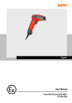
1
BLY1 Barcode 5397007039283
Wireless Alarm System.indd 1
BLY1 Wireless Alarm
System - Version: 01
Wireless
Alarm
System
01/06/2012 10:57
Getting started...
BLY1 Wireless Alarm System
Let’s
get started...
These instructions are for your safety. Please read through them
thoroughly before use and retain them for future reference.
Getting started...
Introduction and Safety Overview of System Planning your Installation
Installing your System In more detail...
Using the System Maintenance Extending the System Specifications Troubleshooting Guide Disposal and Recycling
Appendix
LED Alarm Indications
Zone-Location Table 2
3
4-5
6-8
5-15
16
17-19
19
19
20-21
21
22
23
24
25
1
Wireless Alarm System.indd 2
01/06/2012 10:57
Type box
Getting
started...
Introduction and Safety 3
Overview of System 4-5
Planning your Installation
6-8
Installing your System
Getting started...
BLY1 Wireless Alarm System
9-15
2
Wireless Alarm System.indd 3
01/06/2012 10:57
Introduction & Safety
BLY1 Wireless Alarm System
INTRODUCTION
The wireless alarm system is designed to protect your home. It is a simple to use, easy to
install unit. No special tools or training are required, all fixings are included.
Getting started...
IE
IMPORTANT: Please read this manual carefully, in full, before commencing
installation. You will find installation easier if you follow these steps in the sequence
shown.
SAFETY
Before proceeding with the installation, please note the following safety warnings:
DO NOT connect the mains supply directly to the products, this will cause
permanent damage to the products.
Control panel, adaptor, movement detector and Door/Window contact are for indoor use only.
Avoid mounting location which can expose these product to splashing or dripping liquid.
Always follow the manufacturer’s advice when using any tools power tools, ladder/steps,
using steps or ladders, and wear suitable protective equipment (e.g. safety goggles) when
drilling holes, etc.
The use of ear defenders are advisable when working in close proximity to the External
Siren or the Control Panel’s Siren when the front panel cover is removed due to the high
sound level produced by it.
Before drilling holes in walls, check for hidden electricity cables and water pipes. The use
of a cable/pipe locator is advisable if in doubt.
Batteries (battery pack or batteries installed) should not be exposed to excessive heat.
Danger of damage to the unit may occur if battery is incorrectly replaced.
Replace only with the same or equivalent type (Do not mix batteries type).
3
Wireless Alarm System.indd 4
01/06/2012 10:57
Overview of System
BLY1 Wireless Alarm System
This wireless alarm system is based on wireless radio technology to give exceptional levels
of protection and reliability. It has the ability to control up to eight detectors, three remote keys
(optional accessory) and one wireless siren.
Kit Contents
POWER
TAMPER
3
2
6
5
4
9
8
7
0
m
Anti-Ja
On/Off
Learn
m
Part-Ar
Reset
Arm
Control Unit
This is the heart of the system. It receives signals
from detectors, accepts inputs from user and
activates warnings such as siren and LED.
Wireless Magnetic Contact Detector (MC) (Two Pair)
Uses a magnetically operated switch to sense
the opening/closing of door or window.
Wireless Movement Detector (PIR)(One Unit)
The PIR uses Infra-Red technology to sense the
body heat of a moving person.
One unit can cover an entire room.
External AC adaptor
1x 9V PP3 Alkaline battery
for Control unit backup
Getting started...
1
Wireless External Siren
Gives audible and visual indication
of an alarm condition.
4 x D-Cell Alkaline batteries
for Wireless External Siren
6x AAA 1.5V alkaline batteries
for MC and PIR
You will need
4mm
8mm
4
Wireless Alarm System.indd 5
01/06/2012 10:57
Overview of System
BLY1 Wireless Alarm System
System features
• Detector /Key /External Siren learning – Every wireless device (detector, Key, External Siren) contains an unique identification code. During installation, the control unit will learn which devices belong within your system by receiving coded radio transmissions from each detector.
Getting started...
• This system can control up to eight detectors (every zone can control one wireless detector.)
If the system is triggered, the control unit will indicate which zone the alarm occurred.
• The wireless alarm system has three modes: OFF, Part-Arm, ARM; when entering ARM
or Part-Arm mode, the user has 30 seconds to leave the monitored areas without triggering
the alarm.
Explanation of terms
Zone – A logical area that is monitored by a detector.
Disarmed – (Standby mode) – This is the normal state of the system when the house is
occupied. Enter your four-digit user PIN code to return to OFF state.
Full Alarm – (ARM state) – The control unit will sound full alarm (internal siren) when it
receives alarm signals.
Part Arm – (Home state) – Arming the system so that certain zones omitted (i.e. will not trigger
an alarm). It is typically used to omit the upstairs zones at night when you sleep.
Entry/Exit Zone – The control unit recognise MC zone as entry and/or exit zone.
OK Beep – Rapid double tone; it indicates correct operation.
Error Beep – Long single tone; it indicates incorrect operation.
Anti-Jamming – Detect if jamming exists or not. it can be enabled/disabled
5
Wireless Alarm System.indd 6
01/06/2012 10:57
BLY1 Wireless Alarm System
Planning your Installation
Location of components
Control unit – Location
In choosing a suitable location you should bear in mind:
• The need to reach the control unit easily, within the 30 seconds, when
entering and leaving the premises, ideally passing only one detector.
Getting started...
• The control unit should not be visible from the exterior of the protected premises.
• Reception of radio signals can be affected by the presence of metal objects within a few feet of the control unit. (E.g. mirrors, central heating radiators, garage doors and cars parked in garages on the opposite side of the wall). Avoid any location which is near (within 60cm) to these or any other large metal objects.
Having chosen the location, do not mount at this stage.
Door/Window contact detector (MC) – Location
• These parts contain a radio transmitter and should not be sited near to large metal objects.
• Contains two parts. The larger one (the actual detector) contains the batteries and the electronics. The smaller part is simply a magnet inside.
• Designed to detect a door or window opening. The detector is usually mounted next to it on the door or window. For optimum radio range,
they should be mounted as high as possible.
• In most applications, it is fitted to the front door.
Having chosen the location, do not mount at this stage.
• The detector should not be mounted near to large metal objects or on metal surfaces. It needs to be mounted on a wall or in corner at a height of approximately 2-2.5 meters for the best general coverage in an average room. The detector has been designed to avoid false alarms, nevertheless, it is best to avoid installing the unit where it is facing directly at sources of heat such as fires and boilers and always try to avoid facing at the window. A PIR can look at a radiator but should not be sited above it.
Fire
• Do not site a PIR where its field of view may be obstructed (e.g. by curtains). Also, note that PIR works best when sensing a movement across rather than along their detection beams.
Window
Boiler
2m to 2.5m
Movement/Passive infrared detector (PIR) – Location
Radiator
• Allowing for pets – The PIR senses moving body heat. In some cases, the movement of pets may also be detected. To overcome this it is recommended that the pets are kept in one specific room out of sight of a PIR when the system is armed. If required, additional MC (available
as accessories) can then be used to protect the doors and windows of the room (see section 6 – Extending the System).
Having chosen the location, do not mount at this stage.
6
Wireless Alarm System.indd 7
01/06/2012 10:57
Planning your Installation
BLY1 Wireless Alarm System
Planning the location of system components
Example of a domestic layout
The 2 sample layouts below are intended as guides only but demonstrate two examples of
how a house can be protected with the system.
Getting started...
Sample 1:
Zone Number
Area
Zone
Area
1
Front Door
5
Area of the
control panel
2
Back Door
6
Bedroom 1
3
Window
7
Bedroom 2
4
Living Room
8
Bedroom 3
Dinning
Room
Front door
ZONE 1
Window
ZONE 3
ZONE 5
Control Unit
1st Floor
Back Door
ZONE 2
Living
Room
ZONE 4
Bedroom
2
ZONE 7
Bedroom
1
2nd Floor
Bedroom
3
ZONE 6
ZONE 8
Wirefree
External Siren
7
Wireless Alarm System.indd 8
01/06/2012 10:57
Planning your Installation
BLY1 Wireless Alarm System
The PIRs have been separately placed in bedroom 1, bedroom 2, bedroom 3, and the area
where the control panel is installed, to protect these areas. The Door/Window contact detectors
have been positioned to protect the front door, back door and windows on the 1st floor.
Zone Number
Area
Zone
Area
1
Front Door
5
Area of the
control panel
2
Back Door
6
Kitchen
3
Window
7
Bedroom 2
4
Window
8
Bedroom 3
Front door
ZONE 1
Window
ZONE 3
Dining
Room
Living
Room
ZONE 5
Control Unit
Window
ZONE 4
Getting started...
Sample 2:
Bedroom
2
Wirefree
External Siren
Kitchen
ZONE 6
Back Door
ZONE 2
ZONE 7
Bedroom
1
ZONE 8
The Zone 5 PIR has been placed in the dining room to protect this area where the control panel
is installed. The zone 6, 7, 8 PIRs have been separately placed in the kitchen, bedroom 1
and bedroom 2 to protect these area. Zone 6, 7 and 8 are set as “Home-Bypass zone” so that
these PIRs are disabled when the system is set to “Part Arm” mode. The Door/Window contact
detectors have been positioned to protect the front door, back door and windows.
When the system is installed for the first time or any further detectors are learned to it at any
stage, please follow sections 3.1 to 3.5 explained in this manual to prevent the tamper function
from unnecessarily triggering the alarm of the control unit during installation.
Summary of the steps:
1. Install and power ON the control unit
2. Power up the wireless devices and link to the control unit
3. Power OFF the control unit
4. Install the detectors in their final locations
5. Install the backup battery in the control unit and finally power up the control unit
Wireless Alarm System.indd 9
8
01/06/2012 10:57
Installing your System
BLY1 Wireless Alarm System
Installing the Control unit
• Remove and retain the two holding screws from front cover of control unit and carefully hinge off the front cover.
ST3x25KA
screw
Hole depth ˃22mm
5~6mm
protrude surface
• Place the control unit Tighten the
base mounting screw to
plate on the wall at fasten the
the chosen location. base plate on
surface
Mark and drill 4mm holes for the two Base Plate
mounting screws. Insert 2.6mm thick
wall plugs and have the top mounting screw screwed in to protrude by about 5 to 6mm before hanging the control unit base mounting plate on wall.
98mm
Getting started...
Fitting
• Align the control unit base mounting plate to vertical position before final tightening of both
mounting screws.
Battery Clip
From External
15V Adaptor
•Wire up the Main Power Adaptor to the control unit, but DO NOT plugs the adaptor into the main supply at this stage.
• Do not install the 9V back up battery (provided with this kit) at this stage, but note its installation position for later.
6LR61 size
9V alkaline
battery
Battery
Compartment
Powering the Control unit
Battery
Cover
• Put back the front cover carefully and secure it with the two holding screws, complete with the screw covers (plugs).
• Power up the Main Power Adaptor to power the control unit. The POWER LED will light up and the TAMPER LED will flash since no backup power is installed yet.
•If the alarm sounds then enter the factory user PIN 1234 to silence the system.
Base Mounting
Plate
WARNING: The control
unit must never be
operated from the mains
with the front cover
opened. The user PIN
code is factory set to 1-23-4. If the system sounds
during the installation,
pressing the factory set
code of 1-2-3-4 will silence
the system.
Control Unit
External 15V
Adaptor
2 Pieces of M3 x 10mm
retaining screws
9
Wireless Alarm System.indd 10
01/06/2012 10:57
Installing your System
BLY1 Wireless Alarm System
Power up the Wireless Devices and learning to the CU
1. An adult must carry out battery replacement and installation.
2. Remove exhausted batteries from this product.
3. Do not dispose of batteries in a fire, batteries may explode
or leak.
4. Do not short-circuit the battery terminals.
5. Do not mix used and new batteries.
6. Do not mix alkaline standard (carbon-zinc), lithium or
rechargeable batteries.
7. Do not use rechargeable batteries in this product.
8. Do not recharge non-rechargeable batteries.
9. Do not allow any part to come in contact with heat or a direct flame.
10.Do not allow water to come into contact with the batteries or wiring.
11.Install carefully to prevent any damage to the batteries
12.When installing 2x (AAA 1.5V) batteries in the battery compartment, ensure the batteries are placed as marked (+)(-).
13.Only the recommended batteries should be used.
14.Remove batteries from product when not in use for long periods of time.
15.Keep this product out of the reach of small children.
16.Store unused batteries in their original packaging.
17.Dispose of used batteries responsibly.
The wireless alarm system uses advanced radio technology that under most circumstances
will give more than sufficient transmission range. Before fixing the control unit and
detectors in their selected install position, it is recommended to learn each wireless
detector to the control unit. Please follow the procedure below:
Getting started...
Before powering up the devices please read through this information regarding batteries:
Battery cover
screw
Powering up the wireless siren:
* The use of ear defenders is advisable at this stage *
1. Separate the siren’s front cover from the siren’s base to access the battery compartment.
2. Remove battery cover and insert four LR20 “D” size alkaline batteries in correct polarity as shown indicated in the battery compartment. The siren’s LED will flash to indicate powered up. Refit the battery cover taking care not to press and release the tamper switch located on the rear of the siren’s back plate to prevent the siren from triggering an alarm.
3. If the tamper switch is accidentally press and released then move the power switch to the ‘OFF’ position as shown below to silence the alarm. However, move the switch back to ‘ON’ again ready for it to be learned by the control panel:
“ON/OFF”
siren switch
10
Wireless Alarm System.indd 11
01/06/2012 10:57
Installing your System
BLY1 Wireless Alarm System
Powering up the Wireless PIR Detector(s):
Getting started...
1. Remove battery cover and insert two LR03 “AAA” size alkaline batteries incorrect polarity
as shown.
2. Replace battery compartment cover.
AAA 1.5V
AAA 1.5V
When the PIR is first powered up it will take 2 minutes for it to warm-up before it can be linked
to the control unit.
NOTE: After the first 2 minutes, the PIR will enter a test mode period for the next 15
minutes. During the test mode period, the PIR will constantly detect for movement so
that it gives enough time to link it to the control unit. When this period has expired,
after the PIR detects any further movement, it will go to sleep and not detect any
movement for 2 minutes. This is just an energy saving feature.
Linking the detectors to the Control unit.
1. Press and hold the “Learn” button for over 5 seconds in standby mode to enter learn
mode. The control unit will beep twice to confirm and the learn LED will turn on.
2. Trigger the device within 10 seconds ensuring it is kept at least 0.5m away from the control unit. To trigger:
2.1 a magnetic contact, activate the MC detector by moving the magnet away
(greater than 40mm) from the arrow near the red LED.
LR03 size 1.5V
LR03 size 1.5V
Greater than 40mm
Learn MC
When a MC Detector has been learnt successfully, Z1, Z2, Z3 or Z4 zone LED
(depending on which next zone is unprogrammed) will be constantly lit.
11
Wireless Alarm System.indd 12
01/06/2012 10:57
BLY1 Wireless Alarm System
Installing your System
Learn PIR
When a PIR Detector has been learnt successfully, Z5, Z6, Z7 or Z8 zone LED depending on which next zone is unprogrammed) will flash.
* The use of ear defenders is advisable at this stage*
2.3 a siren, press and release the tamper switch once located on the rear of the siren. The siren will trigger an alarm. After the control unit confirms the siren is linked (both ‘Learn’ and ‘Z4/Z8’ LEDs will flash together), silence the siren again by moving its power switch to ‘OFF’ again before installing it on the wall (see diagram on page 10).
Getting started...
2.2 a PIR Detector, trigger the PIR detector by simply moving your hand in
front of the detector.
Learn PIR
2.4 a Remote Control, (Optional Accessory) press and release the disarm button once.
Learn remote key
When the device is triggered, the first available unprogrammed zone LED for that device will light up on the control unit. The control unit will beep twice to confirm the device has been
learnt and the corresponding zone LED will light up red. (See diagrams below to show which
zone LEDs correspond to which device when learnt). If the device has not been triggered in 10 seconds then re-enter programming mode again (press and hold the “Learn” button for over 5 seconds)
Wireless Alarm System.indd 13
12
01/06/2012 10:57
Installing your System
BLY1 Wireless Alarm System
3. Trigger the next device within 10 seconds to learn it and repeat for additional devices. If the system has reached its maximum capacity and no more devices ca be added. The control unit will not beep any more.
4. When you have finished learning the devices, all zone LEDs will turn off after 10 seconds which indicates successful programming. After this the system returns to standby mode.
Getting started...
Summary of the learn mode LED state
Learn mode
state
Learn
Red LED
Z1/Z5
Red LED
Z2/Z6
Red LED
Z3/Z7
Red LED
Z4/Z8
Red LED
Learn
Wireless MC
ON
ON
ON
ON
ON
Learn
Wireless PIR
ON
FLASH
FLASH
FLASH
FLASH
FLASH
ON
ON
ON
Learn Wireless
Remote Key
(optional
accessory)
Learn
Wireless
External
Siren
FLASH
ON
If you have any additional detectors, make sure they are programmed to the control unit
before location testing and installation.
Powering down the control unit
Turn OFF the Main Power Adaptor so that the POWER LED on the Control unit is OFF.
Installing your detectors
a) Wireless magnetic Door/Window contact (MC) detector
1. Choose where on the door or window you wish to locate Max.
Frame
8mm
the unit. The transmitter unit is usually mounted on the frame and should be positioned such that the red LED is 52mm
close to the door or window.
Door / Window
2. The magnet should be fitted as shown with one narrow
edge level with the flat top on the detector housing.
The gap between the magnet and detector should not be
more than 8mm with the arrow on the magnet pointing directly towards the arrow on
the detector.
3. If there is insufficient room to mount the detector on the frame, then it can be
fixed to the door or window instead (with the magnet fixed to the frame
alongside it.) For reliable operation, the front face of the magnet should be no
more than 8mm from the front face of the detector. In some cases, it may be
necessary to place packing behind the magnet or detector to achieve this.
Fitting
4. Remove and retain the screw from the bottom of the detector. Use a small
drill or screw driver to make two fixing holes in the back plate as a template.
Use the backplate to mark and drill two 4mm fixing holes 80.5mm apart.
Fix the back plate in position using the screws provided.
5. If you wish add an additional wired magnetic Door/Window contact detector,
then connect the wiring to the two hard wire terminals provided.
13
Wireless Alarm System.indd 14
01/06/2012 10:57
Installing your System
BLY1 Wireless Alarm System
Front
cover
retaining
screw
80.5mm
b) Wireless Movement PIR Detector
1. Remove and retain the screw from the bottom of the PIR and lift off the cover.
Fitting
2. If you are fitting the PIR in a corner, use mounting
points “A”. If you are fitting the detector on to a flat
A
surface, use mounting points “B”. The mounting
points are shown by indentations in the plastic
B
molding. Use a small drill to create two fixing holes
at the mounting points.
3.Hold the base of the PIR in the chosen position,
ensuring that the front of PIR will face towards the
centre of the protected area, and mark and drill two
4mm fixing holes in the wall. DO NOT drill holes
with the PIR in position – the resulting dust may
damage the PIR and prevent it from operating.
Secure the PIR to the wall using two screws
(25mm countersink) and the wall plugs.
4. Replace the electronic module into the retaining clips, ensuring that it is
correctly positioned and firmly seated.
Getting started...
4. Locate the detector on the back plate and replace the retaining screw at the base of
the unit.
5. Align the magnet as described above and fix in position with the two screws provided.
NOTE: If you are fitting the unit to a PVC door or window, you may wish to use
STRONG double-sided tape to fix both detector and magnet in position.
c). Wireless external siren
Fitting
1. Mount the siren base on to the wall using screws or fixings that are appropriate
for the construction of the building. Keyhole slots and slide mount are provided
to assist with positioning. It is recommended that all 3 fixing points are used.
2. Once mounted, move the siren’s power switch to ‘ON’ again for normal
operation at this stage (see diagram on page 10).
Tamper protection fixing
3. The tamper switch will touch against the wall, but will not ‘click’ in position at
this stage, provided the wall is a flat surface.
4. When the front cover is fitted and the cover screw moves further in, it will push
the wall tamper switch down against the wall making it ‘click’. This screw when
fully tightened, provides front cover and wall tamper protection.
NOTE: Each time this screw is removed, an alarm will be triggered by the system.
Silence the alarm by entering the user PIN code at the control panel
(factory set PIN 1234).*
Cover screw
Siren front cover
Wireless Alarm System.indd 15
Siren base
Siren top view of front cover
screw when inserted pushes
down the tamper switch
Wall mounting points
14
01/06/2012 10:57
Installing your System
BLY1 Wireless Alarm System
Movement Detector/PIR final setup
Getting started...
IMPORTANT: To extend the battery life, wireless PIR detectors are designed to
detect once only before entering a “Sleep” condition for two minutes during which the
unit will not trigger. Any movement seen by the PIR during this period would cause
“Sleep” conditions to be extended by a further two minutes. Therefore, a wireless PIR
which is constantly sensing movement, such as a person walking around a room,
may appear to be non-functional; you will find that the PIR will detect normally again
following a two minute period with no movement present.
The wireless PIR detector has a jumper link, which activates/deactivates the LED. This LED
can be used when performing a walk test in the chosen installation area to make sure you are
happy with detection coverage. To increase battery life, pull this link off after completing the
walk test. The LED will be off when the detector is triggered during arm. Otherwise, leave the
link on, the LED will be on when triggered.
Powering up the control unit
1. While the control unit is powered OFF, remove the control unit front cover again
(see page 9)
2. Disconnect the battery snap connecting the battery holder. Take out the battery holder.
3.Connect the 9V Alkaline PP3 back up battery to the battery clip and place the battery
into its compartment section.
4.If the alarm sounds then enter the factory User PIN 1234 to silence the system
5.Refit the battery cover. Refit the control unit cover to the base.
6. Power up the main power adaptor again.
The control unit will return to standby ready for operation and the POWER LED will remain ON.
15
Wireless Alarm System.indd 16
01/06/2012 10:57
Getting
started...
In more
detail...
Using the System 17-19
Maintenance 19
Extending the System 19
Specifications 20-21
Troubleshooting Guide
21
Disposal and Recycling
22
In more detail...
Getting started...
BLY1 Wireless Alarm System
16
Wireless Alarm System.indd 17
01/06/2012 10:57
GB
IE
Using the System
BLY1 Wireless Alarm System
Control unit
When the control unit is powered up, it will remain in standby mode. The PIN code can
also disarm the system and put it into standby mode.
a) Changing the user PIN code
The User PIN code is factory set to 1234. It is highly recommended to change the user PIN code immediately after completing the basic installation.
1. Set the system into “standby mode if not already set.
2. The following is a button sequence example of changing User PIN code to 6502:
Current User PIN Code
New User PIN Code
Two short beeps from control unit confirm the operation. A long beep shows the request has not been accepted or the waiting time between two buttons has exceeded 5 seconds.
In more detail...
*User PIN code of 0000 (four zeros) would lock this function. Pressing the reset switch reverts the User PIN code to 1234 and unlocks this function.
b) Clear all programmed zones and reset User PIN code to default 1234
Pressing the reset switch inside the control unit clears all
programmed zones, keys and external siren and reverts the
user PIN code to 1234. It is necessary to open the control unit
cover by removing and retaining the two M3x10mm retaining
screws at the bottom of the control unit (please see section 3.1 for details).
c) Panic/Attack Alarm from control unit
Activated by pressing “Learn” button together with “Anti-Jam
On/Off”, the system will sound the alarm immediately for the preset siren duration (3 minutes at the factory setting).
All four zone LEDs would be illuminated.
Enter User PIN code to return to standby mode.
Press “Reset” button to clear the zone LEDs.
d) Panic/Attack Alarm from Remote control key
(optional accessory)
Activated by pressing “PARTIAL ARM” button together with
“FULL ARM”, the system will sound the alarm immediately for the preset siren duration (3 minutes at the factory setting.) All four zone LED would be illuminated. Pressing “Disarm” button will return it to standby mode. Press “Reset” button at the Control unit to clear the zone LEDs.
e) Silencing the system
1. When the alarm is triggered, enter the User PIN code at the control unit or press “DISARM” button at the remote key (optional accessory) to cancel the alarm and return to standby.
2.If the alarm has not been cancelled, the alarm sound will stop by itself after the preset siren duration time (3 minutes at the factory setting), and the alarm hold indication (zone indicators) of the zone1 to zone 4 will be illuminated, zone 5 to zone 8 will be flashed. Enter user PIN code at the control unit to return or press “DISARM” button at the remote key (optional accessory) to return to standby mode, press “Reset” button to clear the zone LEDs.
f) Arming the alarm system while exiting the house
Press “Arm” button at the control unit or press “FULL ARM” button at the remote key (optional accessory), close the door and leave the house within the exit delay time (30 seconds at factory setting), both PIR and magnetic contact are activated for protection after the exit delay time elapsed. Note: The control unit will suspend the exit delay (30s) count down if the door is opened or a PIR is triggered.
17
Wireless Alarm System.indd 18
01/06/2012 10:57
Using the System
BLY1 Wireless Alarm System
g)Part Arm the alarm system while at home
Press “Part-Arm” button at the control unit or press “PARTIAL ARM” button at the remote key, (optional accessory) close the door and leave the house within the exit delay time
(30 seconds at factory setting,) both PIR and magnetic contact are activated for protection after the exit delay time elapsed. When omitted zones (zone 6 to zone 8 at factory setting) are triggered, they will not activate the alarm. Part-arm can also be used when you are sleeping upstairs at night and wish to protect the ground of your property provided the PIRs of Zones 6-8 are installed upstairs.
When the system is part-armed. Zone 5 PIR is used to protect the area next to the control panel with a delay period (30 seconds at factory setting).
NOTE: If a door/window where a magnetic contact detector is installed (zones 1-4) is
opened, the alarm will activate instantly.
1. Anti-Jamming detection feature
Press and hold the “Anti-Jam On/Off” button for over 10 seconds in standby mode to turn anti-jamming function ON/OFF. The corresponding “Anti-Jam” green LED will turn ON/OFF.
Anti-Jam LED – Green colour (constantly on means enabled, Flashing means jamming
is detected)
Low battery detection
Control unit:
When the Control unit’s backup battery falls
below 7.2V to 7.6V for over one minute,
TAMPER LED will flash to show low battery
status.
PIR Detectors:
The PIR Detectors have a built in buzzer which
wills sound in the event of a low battery status.
Please replace the batteries within 2 weeks.
9V Alkaline
battery
> One
minute
< 7.2V
~ 7.6V
Magnetic Door/Window Contact Detectors:
The magnetic Door/Window contact detectors have a built in buzzer which wills sound in the
event of a low battery status. Please replace the batteries within 2 weeks.
In more detail...
h) Disarm the alarm system while entering the house
When you open the entrance door, the count down warning sound (entry delay time) will be started. Enter your four-digit User PIN code at the control unit or press “DISARM” button at the remote key (optional accessory) within the delay time (30 seconds at factory setting,) system will return to standby mode. At any time, the user PIN code can be entered to set to the standby mode.
When replacing any batteries, ensure you power OFF the control unit completely to prevent the
tamper function from triggering the alarm. After having replaced any batteries, reconnect the
Summary of the detector responses in different mode
Detector
Magnetic
Contact
PIR
Zone 1
Zone 2
Zone 3
Zone 4
Zone 5
Zone 6
Zone 7
Zone 8
Part Arm
mode
Instant
Instant
Instant
Instant
Delay
Disable
Disable
Disable
ARM mode
Delay
Delay
Delay
Delay
Delay
Delay
Delay
Delay
Usage
Exit/Entry
Zone
Protect area far
away from
Exit/Entry Zone
18
Wireless Alarm System.indd 19
01/06/2012 10:57
Using the System/
Maintenance/
Extending the System
BLY1 Wireless Alarm System
Default settings
Parameter
Ex-factory Value
User PIN code
1234
Entry/Exit delay
30 seconds
Siren Duration
3 minutes
In more detail...
Zone allocation for PIR and MC Detectors
Zone 1 to 4
Magnetic Contact
Zone 5 to 8
PIRs
Maintenance
Once every 3 months:
Test all detectors.
Additionally, once every two years:
It is suggested to replace all batteries in wireless detectors and the control unit.
Replace with the same type of battery:
PIR Detector: 2 x AAA 1.5V Alkaline batteries
Magnetic Contact Detector: 2 x AAA 1.5V Alkaline batteries
Remote Control (optional accessory): 1 x CR2032 Lithium coin cell
Siren: 4 x D cell Alkaline batteries
Control Unit: 9V PP3 Alkaline battery
When replacing any batteries, ensure the control unit is powered OFF completely.
REMARK: It is recommended to replace the 9V alkaline battery in the control unit
after the AC power is out of service for a period of times.
Extending the system
A number of accessories are available to extend your system to suit your exact requirements.
When extending the system, please note the system can take up to 4 wireless magnetic Door/
Window contact detectors (in zones1-4), 4 PIR Detectors (in zones 5-8) and up to 3 wireless
remote controls.
Standard remote control (BLY4) – can be used to arm, part-arm, disarm or panic the control
unit system with an operating range of about 60 meters in open field conditions. Please contact
your supplier for more information.
Standard PIR (BLY3) – easy to install, one unit protects a large area.
Standard Door/Window contact (BLY2) – easy to fit, detects opening of a door or window, can
be extended by the addition of wired magnetic contact.
19
Wireless Alarm System.indd 20
01/06/2012 10:57
Specifications
BLY1 Wireless Alarm System
Control unit
Type Housing material Zones Entry/Exit Delay Siren Duration RF Receiver Frequency: Power Supply Back-up battery life Current Consumption Microprocessor based wireless control unit
ABS
8 Alarm Zones–1 detector maximum per zone (8 detectors capacity)
30 seconds
3 minutes
433MHz
15V 500mA 50Hz AC/AC mains adaptor and 1 x 9V DC PP3 Alkaline for back-up power.
Up to 16 Hours on standby (@ full battery capacity)
< 25mA (standby), <90mA (alarm)
Type Housing material LED Mounting height Detection Range Transmission Frequency Transmission Range Power Supply Typical battery life Dual Pyroelectric element with hemispherical lens
ABS
On/off selectable
2 ~ 2.5 meters
12 meters @ 110º
433MHz
150 meters (open air with direct line of sight)
3VDC (2x 1.5V LR03 size AAA alkaline batteries are included)
Up to 18 months
Wireless Door/Window contact detector
Type Magnetically activated switch with option for external wired contact detectors
Housing material ABS
LED Transmission indication
Transmission Frequency 433MHz
Transmission Range 150 meters (open air with direct line of sight)
Power Supply 3VDC (2x 1.5V LR03 size AAA alkaline batteries are included)
Typical battery Life Up to 18 months
Wireless external siren
Type Housing material Transmission Frequency Transmission Range Siren Output Siren time Power Supply Battery Life External audible and visual indication
ABS
433MHz
60 meters (open air with direct line of sight)
100dB min @ 30cm
3 minutes
4 x 1.5V D Cell Alkaline batteries batteries are included
Up to 12 months
In more detail...
Wireless movement detector/PIR
Wireless remote control (optional accessory)
Type Housing material LED Transmission Frequency Transmission Range Power Supply Typical battery Life Microprocessor based wireless remote control key
ABS
Transmission indication
433MHz
60 meters (open air with direct line of sight)
3VDC (1 x CR2032 Lithium Coin size Battery)
Up to 12 months
20
Wireless Alarm System.indd 21
01/06/2012 10:57
Specifications/
Troubleshooting
BLY1 Wireless Alarm System
Control Panel Power Supply Adaptor
Type Housing material Rated Supply Output AC/AC Adaptor with 3-pin UK style
ABS
230VAC 50HZ supply
Extra Low Voltage (AC15V max at 500mA AC)
Troubleshooting
1) Control unit (CU)
Symptoms
Power indicator and all status LEDs are off
without any response
Power indicator does not light up but the status LEDs or TAMPER LEDs are on.
In more detail...
TAMPER (Red) flashing.
No response to wireless detector
transmissions.
Possible causes and cures
No power supply to unit.
Check connectors to mains and alkaline
battery.
Main supply is out. It is operating from alkaline
battery. Check power connections/adaptor.
Low backup battery condition;
replace 9V PP3 Alkaline battery as soon as
possible.
Are detectors programmed correctly?
Are PIR Detectors in warm up time (During
the first 2 minutes from the batteries
installing)?
Are detectors within radio range of the control
unit? Control unit not armed.
2)Wireless Door/Window contact detector (MC)
Symptoms
Does not detect opening of door or window
(Red LED does not flash)
Built-in buzzer makes a sound
Possible causes and cures
Check that batteries are correctly installed.
Check that magnet is correctly positioned.
Batteries are low. Replace batteries
3)Wireless PIR detector (PIR)
Symptoms
Does not detect movement
(Red LED does not flash).
PIR causes false “intruder” alarms.
PIR will not trigger alarm when the system
is set.
Built-in buzzer makes a sound.
Possible causes and cures
Is PIR’s LED turned off?
Is the PIR in its “sleep” condition (See Page 15).
Check that PIR is not pointed at heat sources
or moving objects, and is not mounted above
a radiator or other heater.
PIR in “sleep” condition.
Batteries are low. Replace batteries.
4)Wireless remote control (optional accessory)
Symptoms
Does not transmit
(Red LED does not flash).
Possible causes and cures
Check that the battery is correctly installed.
Battery low, replace battery.
REMARK: if you have any
problem with the wireless alarm
system, press the RESET switch
inside the control unit. The system
will reset to factory default settings,
but the detectors will need to be
re-programmed again.
Reset Switch
21
Wireless Alarm System.indd 22
01/06/2012 10:57
BLY1 Wireless Alarm System
Disposal and recycling/
Warranty
Disposal and Recycling
Batteries and waste electrical products should not be disposed of with household waste.
Please recycle where these facilities exist.
Check with your local authority or retailer for recycling advice.
Declaration
In more detail...
B&Q hereby declares that this wireless product BLY1 is in compliance with the essential
requirements and other relevant provisions of the Radio and Telecommunications Terminal
Equipment (R&TTE) directive, 1995/5/EC.
22
Wireless Alarm System.indd 23
01/06/2012 10:57
BLY1 Wireless Alarm System
Appendix
Appendix
24
Zone - Location Table
25
Appendix
LED Alarm Indication 23
Wireless Alarm System.indd 24
01/06/2012 10:57
Appendix B
BLY1 Wireless Alarm System
GB
IE
LED
STATUS
Power Tamper
(GREEN) (RED)
Z1/Z5
(RED)
Z2/Z6
(RED)
Z3/Z7
(RED)
Z4/Z8
(RED)
Power Ready
ON
X
X
X
X
X
AC Failure
X
X
X
X
X
X
Low Battery
ON
Flashing
X
X
X
X
Z1 Alarm
ON
X
ON
X
X
X
Z2 Alarm
ON
X
X
ON
X
X
Z3 Alarm
ON
X
X
X
ON
X
Z4 Alarm
ON
X
X
X
X
ON
Z5 Alarm
ON
X
Flashing
X
X
X
Z6 Alarm
ON
X
X
Flashing
X
X
Z7 Alarm
ON
X
X
X
Flashing
X
Z8 Alarm
ON
X
X
X
X
Flashing
Z1 Tamper
ON
ON
ON
X
X
X
Z2 Tamper
ON
ON
X
ON
X
X
Z3 Tamper
ON
ON
X
X
ON
X
Z4 Tamper
ON
ON
X
X
X
ON
Z5 Tamper
ON
ON
Flashing
X
X
X
Z6 Tamper
ON
ON
X
Flashing
X
X
Z7 Tamper
ON
ON
X
X
Flashing
X
Z8 Tamper
ON
ON
X
X
X
Flashing
ON
ON
X
X
X
X
ON
ON
X
X
X
X
ON
X
ON
ON
ON
ON
MC
PIR
Control panel
Tamper
External Siren
Tamper
PANIC Alarm
Appendix
LED Alarm Indication:
24
Wireless Alarm System.indd 25
01/06/2012 10:57
Appendix B
BLY1 Wireless Alarm System
Zone - Location Table:
Zone Number
Location
1
2
3
4
5
6
7
Appendix
8
25
B&Q,
Chandlers Ford, Hants,
SO53 3LE United Kingdom
www.diy.com
Customer Helpline 0844 736 9169
Wireless Alarm System.indd 26
EAN 5397007039283
BLY1 Wireless Alarm System - Version 01
01/06/2012 10:57