1
HP ProLiant BL35p Server Blade
Maintenance and Service Guide
Part Number 379103-007
February 2007 (Seventh Edition)
© Copyright 2005-2007 Hewlett-Packard Development Company, L.P.
The information contained herein is subject to change without notice. The only warranties for HP products and services are set forth in the express
warranty statements accompanying such products and services. Nothing herein should be construed as constituting an additional warranty. HP
shall not be liable for technical or editorial errors or omissions contained herein.
Microsoft and Windows are U.S. registered trademarks of Microsoft Corporation.
AMD Opteron is a trademark of Advanced Micro Devices, Inc.
Audience assumptions
This guide is for an experienced service technician. HP assumes you are qualified in the servicing of
computer equipment and trained in recognizing hazards in products with hazardous energy levels and
are familiar with weight and stability precautions for rack installations.
Contents
Illustrated parts catalog ................................................................................................................. 5
Customer self repair................................................................................................................................... 5
ATA models.............................................................................................................................................. 6
Server blade exploded view ............................................................................................................. 6
HP BladeSystem p-Class sleeve and blanks exploded view.................................................................... 6
Spare parts list (ATA models) ............................................................................................................ 7
SAS models .............................................................................................................................................. 8
Server blade exploded view ............................................................................................................. 8
HP BladeSystem p-Class sleeve and blanks exploded view.................................................................... 9
Spare parts list (SAS models) ............................................................................................................ 9
Removal and replacement procedures ........................................................................................... 11
Safety considerations ............................................................................................................................... 11
Preventing electrostatic discharge .................................................................................................... 11
Rack warnings and cautions ........................................................................................................... 12
Preparation procedures ............................................................................................................................ 12
Power down the server blade .......................................................................................................... 13
Remove the server blade ................................................................................................................ 13
ATA drive cage assembly ......................................................................................................................... 14
ATA hard drive option ............................................................................................................................. 14
SAS drive cage assembly ......................................................................................................................... 15
SAS hard drive option ............................................................................................................................. 16
SAS controller and cables ........................................................................................................................ 17
Air baffle (dual-core processor models only)................................................................................................ 18
DIMMs................................................................................................................................................... 19
Processor ............................................................................................................................................... 20
Fan assembly.......................................................................................................................................... 23
Dual Port Fibre Channel Adapter (2 GB) .................................................................................................... 24
NIC riser board ...................................................................................................................................... 24
Power converter module ........................................................................................................................... 25
Power button/LED cable........................................................................................................................... 26
Server blade handle ................................................................................................................................ 26
System board assembly............................................................................................................................ 27
Server blade blanks................................................................................................................................. 28
HP BladeSystem p-Class sleeve ................................................................................................................. 28
HP BladeSystem p-Class sleeve board ........................................................................................................ 29
Diagnostic tools .......................................................................................................................... 31
Troubleshooting resources ........................................................................................................................ 31
HP Insight Diagnostics.............................................................................................................................. 31
Survey Utility .......................................................................................................................................... 31
Integrated Management Log ..................................................................................................................... 32
HP Instant Support Enterprise Edition.......................................................................................................... 32
Web-Based Enterprise Service .................................................................................................................. 32
Open Services Event Manager.................................................................................................................. 33
Component identification ............................................................................................................. 34
Contents
3
Server blade components ......................................................................................................................... 34
Front panel components and LEDs.................................................................................................... 34
Internal components....................................................................................................................... 36
System maintenance switch............................................................................................................. 37
Sleeve board and server blade LED locations.............................................................................................. 37
Local I/O cable ...................................................................................................................................... 38
Server blade enclosure bay numbering ...................................................................................................... 38
Server blade enclosure compatibility.......................................................................................................... 39
Specifications ............................................................................................................................. 40
Environmental specifications ..................................................................................................................... 40
Server blade specifications ....................................................................................................................... 40
Acronyms and abbreviations........................................................................................................ 41
Index......................................................................................................................................... 43
Contents
4
Illustrated parts catalog
In this section
Customer self repair ................................................................................................................................. 5
ATA models............................................................................................................................................. 6
SAS models ............................................................................................................................................. 8
Customer self repair
What is customer self repair?
HP's customer self-repair program offers you the fastest service under either warranty or contract. It
enables HP to ship replacement parts directly to you so that you can replace them. Using this program,
you can replace parts at your own convenience.
A convenient, easy-to-use program:
•
An HP support specialist will diagnose and assess whether a replacement part is required to address
a system problem. The specialist will also determine whether you can replace the part.
•
Replacement parts are express-shipped. Most in-stock parts are shipped the very same day you
contact HP. You may be required to send the defective part back to HP, unless otherwise instructed.
•
Available for most HP products currently under warranty or contract. For information on the warranty
service, refer to the HP website
(http://h18004.www1.hp.com/products/servers/platforms/warranty/index.html).
For more information about HP's customer self-repair program, contact your local service provider. For the
North American program, refer to the HP website (http://www.hp.com/go/selfrepair).
Customer replaceable parts are identified in the following tables.
Illustrated parts catalog 5
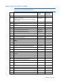
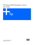
ATA models
Server blade exploded view
HP BladeSystem p-Class sleeve and blanks exploded view
Illustrated parts catalog 6
Spare parts list (ATA models)
NOTE: Always retain the server blade handle. The handle contains a serial number that
maintains the original server blade warranty.
Item
Description
Spare part
number
Customer
replaceable?
381803-001
Yes
Processor
—
—
a) 2.4-GHz AMD Opteron™ single-core
381836-001
Yes
b) 1.8-GHz AMD Opteron™ dual-core
395083-001
Yes
c) 2.0-GHz AMD Opteron™ dual-core
395084-001
Yes
d) 2.2-GHz AMD Opteron™ dual-core
395085-001
Yes
e) 2.4-GHz AMD Opteron™ dual-core
414452-001
Yes
3
Fan assembly
361748-001
Yes
4
NIC riser board, mezzanine
361745-001
Yes
5
Power converter module
361752-001
Yes
DIMMs
—
—
a) DIMM, 512-MB, PC3200 DDR 400-MHz SDRAM
381817-001
Yes
b) DIMM, 1-GB, PC3200 DDR 400-MHz SDRAM
381818-001
Yes
c) DIMM, 2-GB, PC3200 DDR 400-MHz SDRAM
381819-001
Yes
d) DIMM, 4-GB, PC2700 DDR 333-MHz SDRAM
416258-001
Yes
Heatsinks
—
—
a) Heatsink, single-core processor
381804-001
Yes
b) Heatsink, dual-core processor
396768-001
Yes
Dual Port Fibre Channel Adapters (2 GB)
—
—
a) QLogic-based Dual Port Fibre Channel Adapter (2-GB)
361744-001
Yes
b) Emulex-based Dual Port Fibre Channel Adapter (2GB)*
399852-001
Yes
9
Hard drive, 60-GB, ATA
361751-001
Yes
10
Hardware kit
361750-001
Yes
a) 3U server blade blank
—
—
b) Drive cage assembly
—
—
HP BladeSystem p-Class sleeve access panel
361881-001
Yes
Mechanical components
1
System board assembly,
with two single-core heatsinks, two dual-core heatsinks,
and LED board
System components
2
Memory
6
Miscellaneous
7
8
11
Illustrated parts catalog 7
Item
Description
Spare part
number
Customer
replaceable?
12
HP BladeSystem p-Class sleeve board
361746-001
Yes
13
Air baffle (dual-core processor systems only)
398028-001
Yes
14
Cable kit *
381805-001
Yes
a) Power button/LED cable
—
—
b) Hard drive cable
—
—
15
Replacement battery, 3-V lithium *
234556-001
Yes
16
Local I/O cable *
355935-001
Yes
*Not shown
SAS models
Server blade exploded view
Illustrated parts catalog 8
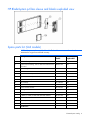
HP BladeSystem p-Class sleeve and blanks exploded view
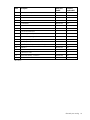
Spare parts list (SAS models)
NOTE: Always retain the server blade handle. The handle contains a serial number that
maintains the original server blade warranty.
Item
Description
Spare part
number
Customer
replaceable?
404677-001
Yes
Processor
—
—
a) 1.8-GHz AMD Opteron™ dual-core
395083-001
Yes
b) 2.2-GHz AMD Opteron™ dual-core
395085-001
Yes
c) 2.4-GHz AMD Opteron™ dual-core
414452-001
Yes
3
Fan assembly
361748-001
Yes
4
NIC riser board, mezzanine
381816-001
Yes
5
Power converter module
361752-001
Yes
DIMMs
—
—
a) DIMM, 512-MB, PC3200 DDR 400-MHz SDRAM
381817-001
Yes
b) DIMM, 1-GB, PC3200 DDR 400-MHz SDRAM
381818-001
Yes
c) DIMM, 2-GB, PC3200 DDR 400-MHz SDRAM
381819-001
Yes
d) DIMM, 4-GB, PC2700 DDR 333-MHz SDRAM
416258-001
Yes
Mechanical components
1
System board assembly, with two dual-core heatsinks and
LED board
System components
2
Memory
6
Miscellaneous
Illustrated parts catalog 9
Item
Description
Spare part
number
Customer
replaceable?
7
Heatsink, dual-core processor
396768-001
Yes
8
SAS controller
403624-001
Yes
9
Hard drives
—
—
a) 36-GB SAS
404784-001
Yes
b) 72-GB SAS
404785-001
Yes
c) 146-GB SAS
437862-001
Yes
Hardware kit
404678-001
Yes
a) 3U server blade blank
—
—
b) Drive cage assembly *
—
—
c) Latch release, spring, and screw *
—
—
11
HP BladeSystem p-Class sleeve access panel
361881-001
Yes
12
HP BladeSystem p-Class sleeve board
361746-001
Yes
13
Air baffle (dual-core processor systems only)
398028-001
Yes
14
Cable kit *
403623-001
Yes
a) Power button/LED cable
—
—
b) Hard drive cable
—
—
15
Replacement battery, 3-V lithium *
234556-001
Yes
16
Local I/O cable *
355935-001
Yes
10
*Not shown
Illustrated parts catalog 10
Removal and replacement procedures
In this section
Safety considerations.............................................................................................................................. 11
Preparation procedures........................................................................................................................... 12
ATA drive cage assembly........................................................................................................................ 14
ATA hard drive option ............................................................................................................................ 14
SAS drive cage assembly ........................................................................................................................ 15
SAS hard drive option ............................................................................................................................ 16
SAS controller and cables ....................................................................................................................... 17
Air baffle (dual-core processor models only) .............................................................................................. 18
DIMMs.................................................................................................................................................. 19
Processor .............................................................................................................................................. 20
Fan assembly......................................................................................................................................... 23
Dual Port Fibre Channel Adapter (2 GB) ................................................................................................... 24
NIC riser board ..................................................................................................................................... 24
Power converter module.......................................................................................................................... 25
Power button/LED cable.......................................................................................................................... 26
Server blade handle ............................................................................................................................... 26
System board assembly........................................................................................................................... 27
Server blade blanks................................................................................................................................ 28
HP BladeSystem p-Class sleeve ................................................................................................................ 28
HP BladeSystem p-Class sleeve board....................................................................................................... 29
Safety considerations
Before performing service procedures, review all the safety information.
Preventing electrostatic discharge
To prevent damaging the system, be aware of the precautions you need to follow when setting up the
system or handling parts. A discharge of static electricity from a finger or other conductor may damage
system boards or other static-sensitive devices. This type of damage may reduce the life expectancy of the
device.
To prevent electrostatic damage:
•
Avoid hand contact by transporting and storing products in static-safe containers.
•
Keep electrostatic-sensitive parts in their containers until they arrive at static-free workstations.
•
Place parts on a grounded surface before removing them from their containers.
•
Avoid touching pins, leads, or circuitry.
•
Always be properly grounded when touching a static-sensitive component or assembly.
Removal and replacement procedures 11
Rack warnings and cautions
WARNING: To reduce the risk of personal injury or damage to the equipment, be sure that:
• The leveling jacks are extended to the floor.
• The full weight of the rack rests on the leveling jacks.
• The stabilizing feet are attached to the rack if it is a single-rack installation.
• The racks are coupled together in multiple-rack installations.
• Only one component is extended at a time. A rack may become unstable if more than one
component is extended for any reason.
WARNING: To reduce the risk of personal injury or equipment damage when unloading a
rack:
• At least two people are needed to safely unload the rack from the pallet. An empty 42U
rack can weigh as much as 115 kg (253 lb), can stand more than 2.1 m (7 ft) tall, and
may become unstable when being moved on its casters.
• Never stand in front of the rack when it is rolling down the ramp from the pallet. Always
handle the rack from both sides.
WARNING: This server blade enclosure is very heavy. To reduce the risk of personal injury or
damage to the equipment:
• Observe local occupational health and safety requirements and guidelines for manual
material handling.
• Get help to lift and stabilize the product during installation or removal, especially when the
product is not fastened to the rails. When the server blade enclosure weighs more than
22.5 kg (50 lb), at least two people must lift the server blade enclosure into the rack
together. A third person may be required to help align the server blade enclosure if the
server blade is installed higher than chest level.
• Use caution when installing the server blade enclosure in or removing the server blade
enclosure from the rack; it is unstable when not fastened to the rails.
WARNING: To reduce the risk of personal injury from hot surfaces, allow the drives and the
internal system components to cool before touching them.
Preparation procedures
To access some components and perform certain service procedures:
•
Back up all critical data.
•
Power down the server blade (on page 13).
For non-hot-plug service procedures, use the methods available to power down the server blade.
•
Remove the server blade (on page 13).
Access to internal server blade components requires removal from the server blade enclosure and HP
ProLiant p-Class sleeve.
Removal and replacement procedures 12
Power down the server blade
Before powering down the server blade, always back up critical data.
Power down the server blade using either of the following methods:
•
Press the Power On/Standby button on the server blade front panel.
Be sure that the server blade is in standby mode by observing that the power LED is amber. This
process may take 30 seconds, during which time some internal circuitry remains active.
•
Use the virtual power button feature in iLO.
After initiating a manual or virtual power down command, be sure that the server blade goes into
standby mode by observing that the power LED is amber.
IMPORTANT: When the server blade is in standby mode, auxiliary power is still being
provided. To remove all power from the server blade, remove the server blade from the server
blade enclosure. Removing the sleeve from the server blade enclosure is not necessary.
IMPORTANT: Remote power procedures require the most recent firmware for the power
enclosure and server blade enclosure management modules. For the most recent firmware,
refer to the HP website (http://www.hp.com/go/support).
Remove the server blade
1.
Back up all server blade data.
2.
Power down the server blade (on page 13).
3.
Remove the server blade from the HP BladeSystem p-Class sleeve.
WARNING: To reduce the risk of personal injury from hot surfaces, allow the drives and the
internal system components to cool before touching them.
CAUTION: To prevent damage to electrical components, properly ground the server blade
before beginning any installation procedure. Improper grounding can cause ESD.
Removal and replacement procedures 13
ATA drive cage assembly
To remove the component:
1.
Power down the server blade (on page 13).
2.
Remove the server blade (on page 13).
3.
Remove the drive cage assembly.
IMPORTANT: Be sure to disconnect the hard drive cable from the system board before
removing the drive cage assembly.
To replace the component, reverse the removal procedure.
ATA hard drive option
To remove the component:
1.
Power down the server blade (on page 13).
2.
Remove the server blade (on page 13).
3.
Remove the ATA drive cage assembly (on page 14).
Removal and replacement procedures 14
4.
Remove the cover plate and, if necessary, the center plate.
5.
Remove the drive from the cage.
To replace the component, reverse the removal procedure.
The drive cage assembly lower drive bay is designated as the primary hard drive bay and must be
populated first.
Before installing a hard drive, be sure the jumper on the hard drive is set to CS so that the drive device ID
is determined by the hard drive connection to the hard drive cable.
SAS drive cage assembly
To remove the component:
1.
Power down the server blade (on page 13).
2.
Remove the server blade (on page 13).
Removal and replacement procedures 15
3.
Remove the drive cage assembly.
To replace the component, reverse the removal procedure.
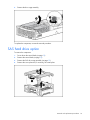
SAS hard drive option
To remove the component:
1.
Power down the server blade (on page 13).
2.
Remove the server blade (on page 13).
3.
Remove the SAS drive cage assembly (on page 15).
4.
Remove the cover plate and, if necessary, the center plate.
Removal and replacement procedures 16
5.
Remove the hard drive.
To replace the component, reverse the removal procedure.
The drive cage assembly lower drive bay is designated as the primary hard drive bay and must be
populated first.
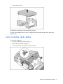
SAS controller and cables
To remove the component:
1.
Power down the server blade (on page 13).
2.
Remove the server blade (on page 13).
3.
Disconnect the hard drive cables from the hard drives.
Removal and replacement procedures 17
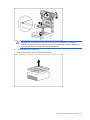
4.
Disconnect the cables from the controller.
5.
Remove the SAS controller.
To replace the component, reverse the removal procedure.
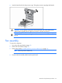
Air baffle (dual-core processor models only)
To remove the component:
1.
Power down the server blade (on page 13).
2.
Remove the server blade (on page 13).
Removal and replacement procedures 18
3.
Remove the air baffle.
CAUTION: To ensure proper airflow, always install the air baffle when installing a dual-core
processor.
To replace the component, reverse the removal procedure.
DIMMs
To remove the component:
1.
Power down the server blade (on page 13).
2.
Remove the server blade (on page 13).
3.
For DIMM bank B, remove the air baffle. ("Air baffle (dual-core processor models only)" on page
18)
NOTE: Dual-core processor models only.
Removal and replacement procedures 19
4.
Remove the DIMM.
To replace the component, reverse the removal procedure.
CAUTION: Use only HP DIMMs. DIMMs from other sources may adversely affect data
integrity.
Observe the following DIMM installation guidelines:
•
All DIMMs must be PC3200 DDR 400-MHz SDRAM DIMMs, or PC2700 DDR 333-MHz SDRAM
DIMMs.
•
Both DIMM slots in a bank must be populated.
•
Both DIMMs in a bank must be identical.
•
DIMM bank A must always be populated.
•
DIMM bank B is only active when processor socket 2 is populated.
•
Each processor should have a populated memory bank, for best performance.
Processor
To remove the component:
1.
Power down the server blade (on page 13).
2.
Remove the server blade (on page 13).
CAUTION: Removal of the processor or heatsink renders the thermal layer between the
processor and heatsink useless. A new heatsink must be ordered and installed before
reinstalling the processor.
Removal and replacement procedures 20
3.
Open the processor cage and remove the heatsink.
IMPORTANT: Processor socket 1 must always be populated. If processor socket 1 is empty, the
server blade does not power up.
4.
Remove the processor.
To replace the component:
1.
Install the processor.
CAUTION: Be sure that the processor socket locking lever is open before installing the
processor into the socket.
CAUTION: The processor is designed to fit one way into the socket. Use the alignment guides
on the processor and socket to properly align the processor with the socket. Refer to the server
blade hood label for specific instructions.
CAUTION: Do not bend or damage the pins beneath the processor.
Removal and replacement procedures 21
CAUTION: Be sure that the processor socket locking lever is closed after the processor is
installed. The lever should close without resistance. Forcing the lever closed can damage the
processor and socket, requiring system board replacement.
2.
Close the processor locking lever.
3.
Remove the protective cover from the thermal interface.
Removal and replacement procedures 22
4.
Insert the heatsink and close the processor cage. Closing the processor cage aligns the heatsink.
CAUTION: To ensure proper cooling of the dual-core processor, the old air baffle must be
replaced when upgrading from a single-core processor to a dual-core processor.
IMPORTANT: To ensure proper cooling, be sure the correct processor air baffle is installed at
all times.
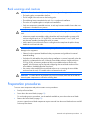
Fan assembly
To remove the component:
1.
Power down the server blade (on page 13).
2.
Remove the server blade (on page 13).
3.
Remove the air baffle ("Air baffle (dual-core processor models only)" on page 18).
NOTE: Dual-core processor models only.
4.
Disconnect the fan assembly cables from the system board.
Removal and replacement procedures 23
5.
Remove the fan assembly.
To replace the component, reverse the removal procedure.
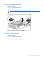
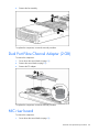
Dual Port Fibre Channel Adapter (2 GB)
To remove the component:
1.
Power down the server blade (on page 13).
2.
Remove the server blade (on page 13).
3.
Remove the FC adapter.
To replace the component, reverse the removal procedure.
NIC riser board
To remove the component:
1.
Power down the server blade (on page 13).
Removal and replacement procedures 24
2.
Remove the server blade (on page 13).
3.
Remove the Dual Port Fibre Channel Adapter, if installed ("Dual Port Fibre Channel Adapter (2 GB)"
on page 24).
4.
Remove the NIC riser board.
To replace the component, reverse the removal procedure.
Power converter module
To remove the component:
1.
Power down the server blade (on page 13).
2.
Remove the server blade (on page 13).
3.
Remove the power converter module.
WARNING: To reduce the risk of personal injury from hot surfaces, allow the drives and the
internal system components to cool before touching them.
Removal and replacement procedures 25
To replace the component, reverse the removal procedure.
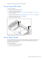
Power button/LED cable
To remove the component:
1.
Power down the server blade (on page 13).
2.
Remove the server blade (on page 13).
3.
Remove the drive cage assembly ("ATA drive cage assembly" on page 14, "SAS drive cage
assembly" on page 15).
4.
Remove the air baffle, if necessary ("Air baffle (dual-core processor models only)" on page 18).
5.
Remove the fan assembly ("Fan assembly" on page 23).
6.
Remove the power button/LED cable.
To replace the component, reverse the removal procedure.
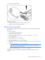
Server blade handle
The server blade handle contains a serial number that maintains the original server blade warranty.
When replacing a system board assembly, remove the server blade handle and install it on the
replacement system board assembly.
To remove the component:
1.
Power down the server blade (on page 13).
2.
Remove the server blade (on page 13).
Removal and replacement procedures 26
3.
Remove the server blade handle.
To replace the component:
1.
Place the server blade handle over the spring on the server blade.
2.
Install the screw to secure the handle and spring.
System board assembly
The system board assembly consists of the system board, the chassis, the power button/LED board, and
the two cables.
To remove the component:
1.
Power down the server blade (on page 13).
2.
Remove the server blade (on page 13).
3.
Remove the drive cage assembly ("ATA drive cage assembly" on page 14, "SAS drive cage
assembly" on page 15).
4.
Remove all DIMMs ("DIMMs" on page 19).
5.
Remove the processors ("Processor" on page 20).
6.
Remove the fan assembly ("Fan assembly" on page 23).
7.
Remove the Dual Port Fibre Channel Adapter, if installed ("Dual Port Fibre Channel Adapter (2 GB)"
on page 24).
8.
Remove the NIC riser board ("NIC riser board" on page 24).
NOTE: Always retain the server blade handle. The handle contains a serial number that
maintains the original server blade warranty.
9.
Remove the server blade handle ("Server blade handle" on page 26).
To replace the component, reinstall all removed subcomponents in the replacement system board
assembly.
Removal and replacement procedures 27
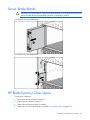
Server blade blanks
CAUTION: To prevent improper cooling and thermal damage, do not operate the server blade
enclosure unless all bays are populated with either a component or a blank.
To remove the 6U server blade blank:
To remove the 3U server blade blank:
HP BladeSystem p-Class sleeve
To remove the component:
1.
Power down the server blade (on page 13).
2.
Remove the server blade (on page 13).
3.
Remove the second server blade, if installed.
4.
Remove any 3U server blade blanks, if installed ("Server blade blanks" on page 28).
Removal and replacement procedures 28
5.
Remove the HP BladeSystem p-Class sleeve.
To replace the component, reverse the removal procedure.
HP BladeSystem p-Class sleeve board
To remove the component:
1.
Remove the HP BladeSystem p-Class sleeve ("HP BladeSystem p-Class sleeve" on page 28).
2.
Remove the HP BladeSystem p-Class sleeve access panel.
Removal and replacement procedures 29
3.
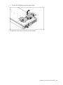
Remove the HP BladeSystem p-Class sleeve board.
To replace the component, reverse the removal procedure.
Removal and replacement procedures 30
Diagnostic tools
In this section
Troubleshooting resources ....................................................................................................................... 31
HP Insight Diagnostics............................................................................................................................. 31
Survey Utility.......................................................................................................................................... 31
Integrated Management Log .................................................................................................................... 32
HP Instant Support Enterprise Edition ........................................................................................................ 32
Web-Based Enterprise Service ................................................................................................................. 32
Open Services Event Manager................................................................................................................. 33
Troubleshooting resources
The HP ProLiant Servers Troubleshooting Guide provides simple procedures for resolving common
problems as well as a comprehensive course of action for fault isolation and identification, error message
interpretation, issue resolution, and software maintenance.
To obtain the guide, refer to any of the following sources and then select the HP ProLiant Servers
Troubleshooting Guide:
•
The server-specific Documentation CD
•
The Business Support Center on the HP website (http://www.hp.com/support). Navigate to the
server technical support page. Under self-help resources, select ProLiant Troubleshooting Guide.
•
The Technical Documentation website (http://www.docs.hp.com). Select Enterprise Servers,
Workstations and Systems Hardware, and then the appropriate server.
HP Insight Diagnostics
HP Insight Diagnostics is a proactive server blade management tool, available in both offline and online
versions, that provides diagnostics and troubleshooting capabilities to assist IT administrators who verify
server blade installations, troubleshoot problems, and perform repair validation.
HP Insight Diagnostics Offline Edition performs various in-depth system and component testing while the
OS is not running. To run this utility, launch the SmartStart CD.
HP Insight Diagnostics Online Edition is a web-based application that captures system configuration and
other related data needed for effective server blade management. Available in Microsoft® Windows®
and Linux versions, the utility helps to ensure proper system operation.
For more information or to download the utility, refer to the HP website
(http://www.hp.com/servers/diags).
Survey Utility
Survey Utility, a feature within HP Insight Diagnostics (on page 31), gathers critical hardware and
software information on ProLiant server blades.
Diagnostic tools 31
This utility supports operating systems that may not be supported by the server blade. For operating
systems supported by the server blade, refer to the HP website (http://www.hp.com/go/supportos).
If a significant change occurs between data-gathering intervals, the Survey Utility marks the previous
information and overwrites the Survey text files to reflect the latest changes in the configuration.
Survey Utility is installed with every SmartStart-assisted installation or can be installed through the HP PSP.
NOTE: The current version of SmartStart provides the memory spare part numbers for the
server blade. To download the latest version, see the HP website
(http://www.hp.com/go/ssdownloads).
Integrated Management Log
The IML records hundreds of events and stores them in an easy-to-view form. The IML timestamps each
event with 1-minute granularity.
You can view recorded events in the IML in several ways, including the following:
•
From within HP SIM
•
From within Survey Utility (on page 31)
•
From within operating system-specific IML viewers
o
For NetWare: IML Viewer
o
For Windows®: IML Viewer
o
For Linux: IML Viewer Application
•
From within the iLO user interface
•
From within HP Insight Diagnostics (on page 31)
For more information, refer to the Management CD in the HP ProLiant Essentials Foundation Pack.
HP Instant Support Enterprise Edition
ISEE is a proactive remote monitoring and diagnostic tool to help manage your systems and devices, a
feature of HP support. ISEE provides continuous hardware event monitoring and automated notification to
identify and prevent potential critical problems. Through remote diagnostic scripts and vital system
configuration information collected about your systems, ISEE enables fast restoration of your systems.
Install ISEE on your systems to help mitigate risk and prevent potential critical problems.
For more information on ISEE, refer to the HP website
(http://www.hp.com/hps/hardware/hw_enterprise.html).
To download HP ISEE, visit the HP website (http://www.hp.com/hps/hardware/hw_downloads.html).
For installation information, refer to the HP ISEE Client Installation and Upgrade Guide
(ftp://ftp.hp.com/pub/services/hardware/info/isee_client.pdf).
Web-Based Enterprise Service
WEBES enables administrators to manage hardware events proactively, either locally or online. The
service provides real-time multiple event analysis, crash analysis, and notification, locally through SMTP
Diagnostic tools 32
and remotely through ISEE for OpenVMS, Tru64, and Microsoft® Windows® operating system binary
error logs.
For more information, refer to the HP website (http://h18000.www1.hp.com/support/svctools/).
Open Services Event Manager
OSEM is a standalone tool that performs real-time reactive and proactive service event filtering, analysis,
and notification. The tool gathers event data from SNMP traps or information provided over an HTTP
interface and notifies an administrator or HP through SMTP and ISEE.
For more information, refer to the HP website (http://h18000.www1.hp.com/support/svctools/).
Diagnostic tools 33
Component identification
In this section
Server blade components ........................................................................................................................ 34
Sleeve board and server blade LED locations ............................................................................................ 37
Local I/O cable ..................................................................................................................................... 38
Server blade enclosure bay numbering ..................................................................................................... 38
Server blade enclosure compatibility ........................................................................................................ 39
Server blade components
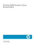
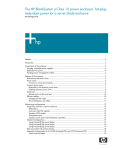
Front panel components and LEDs
Item
Description
Status
1
UID LED
Blue = Identified
Blue flashing = Active remote
management
Off = No active remote management
2
Internal system health LED
Green = Normal
Green flashing = Booting
Amber = Degraded condition
Red = Critical condition
3
NIC 1 LED*
Green = Network linked
Green flashing = Network activity
Off = No link or activity
Component identification 34
Item
Description
Status
4
NIC 2 LED*
Green = Network linked
Green flashing = Network activity
Off = No link or activity
5
Hard drive activity LED
Green/Flashing = Activity
Off = No activity
6
Power On/Standby button
LED
Green = On
Amber = Standby (auxiliary power
available)
Off = Off
7
Local I/O port**
—
* Actual NIC numeration depends on several factors, including the operating system installed on the server blade.
** The Local I/O port is used with the local I/O cable for local management and for connecting external devices to
the server blade, such as USB keyboard, USB mouse, video monitor, USB diskette drive, and USB CD-ROM drive.
Component identification 35
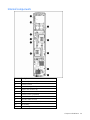
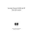
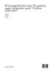
Internal components
Item
Description
1
Fan assembly connectors (2)
2
Processor socket 2
3
DIMM bank A (populated)
4
Adapter card connectors (2)
5
Battery
6
Processor socket 1 (populated)
7
DIMM bank B
8
Hard drive cable connector
9
System maintenance switch (SW1)
10
Fan assembly
11
Hard drive cage
Component identification 36
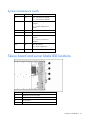
System maintenance switch
Position
Default
Function
S1
Off
Off = iLO security is enabled.
On = iLO security is disabled.
S2
Off
Off = System configuration can be
changed.
On = System configuration is
locked.
S3
Off
Reserved
S4
Off
Reserved
S5
Off
Off = Power-on password is
enabled.
On = Power-on password is
disabled.
S6
Off
Off = No function
On = Clear configuration
S7, S8
Off, Off
Reserved
Sleeve board and server blade LED locations
Item
Description
1
Blade sleeve power LED (CR6)
2
Power converter module LED (CR1)
3
FC LED (CR3)
4
Blade sleeve power LED (CR7)
Component identification 37
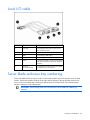
Local I/O cable
Item
Connector
Description
1
Local I/O
For connecting to the local I/O port on the
server blade front panel
2
Video
For connecting a video monitor
3
USB 1
For connecting a USB device
4
USB 2
For connecting a USB device
5
Serial
For trained personnel to connect a null-modem
serial cable and perform advanced diagnostic
procedures
6
iLO RJ-45
(10/100 Ethernet)
For connecting an Ethernet to the server blade
iLO interface from a client device
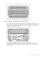
Server blade enclosure bay numbering
Each server blade enclosure requires a pair of interconnect modules to provide network access for data
transfer. Interconnect modules reside in the far right and far left bays of the server blade enclosure. Be
sure to review server blade bay numbering to determine the HP ProLiant BL35p Server Blade external
network connections on the interconnects.
IMPORTANT: When looking at the rear of the enclosure, server blade bay numbering is
reversed.
Component identification 38
Server blade enclosure compatibility
The HP ProLiant BL35p Server Blades require the support of an HP BladeSystem p-Class sleeve in a server
blade enclosure with enhanced backplane components (enhanced server blade enclosure). The enhanced
server blade enclosure also provides a single rear iLO connector for single-cable remote management of
all installed HP ProLiant BL35p Server Blades.
For more information about the enhanced server blade enclosure, refer to the HP ProLiant BL p-Class
Server Blade Enclosure Upgrade Installation Guide or the HP ProLiant BL p-Class Server Blade Enclosure
Installation Guide.
Component identification 39
Specifications
In this section
Environmental specifications .................................................................................................................... 40
Server blade specifications...................................................................................................................... 40
Environmental specifications
Specification
Value
Temperature range*
Operating
10°C to 35°C (50°F to 95°F)
Shipping
-40°C to 60°C (-40°F to 140°F)
Storage
-20°C to 60°C (-4°F to 140°F)
Maximum wet bulb temperature
30°C (86°F)
Relative humidity
(noncondensing)**
Operating
10% to 90%
Shipping
10% to 90%
Storage
10% to 95%
* All temperature ratings shown are for sea level. An altitude derating of 1°C per 304.8 m (1.8°F per 1,000 ft) to
3048 m (10,000 ft) is applicable. No direct sunlight allowed. Upper operating limit is 3,048m (10,000 ft) or 70
Kpa/10.1 psia. Upper non-operating limit is 9,144 m (30,000 ft) or 30.3 KPa/4.4 psia.
** Storage maximum humidity of 95% is based on a maximum temperature of 45°C (113°F). Altitude maximum for
storage corresponds to a pressure minimum of 70 KPa.
Server blade specifications
Specification
Value
Height
4.1 cm (1.61 in)
Depth
64.4 cm (25.35 in)
Width
12.0 cm (4.72 in)
Weight (maximum)
3.72 kg (8.19 lb)
Weight (no drives installed)
3.52. kg (7.76 lb)
Specifications
40
Acronyms and abbreviations
DDR
double data rate
ESD
electrostatic discharge
FC
Fibre Channel
I/O
input/output
iLO
Integrated Lights-Out
IML
Integrated Management Log
IP
Internet Protocol
ISEE
Instant Support Enterprise Edition
LED
light-emitting diode
NIC
network interface controller
OSEM
Open Services Event Manager
POST
Power-On Self Test
Acronyms and abbreviations
41
PSP
ProLiant Support Pack
RBSU
ROM-Based Setup Utility
RILOE
Remote Insight Lights-Out Edition
ROM
read-only memory
SFP
small form-factor pluggable
SIM
Systems Insight Manager
SNMP
Simple Network Management Protocol
UID
unit identification
WEBES
Web-Based Enterprise Service
Acronyms and abbreviations
42
Index
A
adapters 36
air baffle 18
ATA hard drives 14
B
board components 36
buttons 34
C
cable connector identification 38
cables 38
cabling 38
cautions 12
component identification 34, 36, 37
connectors 34, 36, 38
CSR (customer self repair) 5
customer self repair (CSR) 5
D
default settings 37
diagnostic tools 31
diagnostics utility 31
DIMM installation guidelines 19
DIMM slots 36
DIMMs 19
drive cage assembly, ATA 14
drive cage assembly, SAS 15
Dual Port FC Adapter 24
E
electrostatic discharge 11
environmental specifications 40
exploded view 6
F
fan assembly 23
Fibre Channel adapters 36
front panel buttons 34
front panel components 34
front panel LEDs 34
H
HP BladeSystem p-Class sleeve 28, 37
HP BladeSystem p-Class sleeve board 29
HP Insight Diagnostics 31
I
illustrated parts catalog 5
iLO connector 38, 39
Insight Diagnostics 31
Instant Support Enterprise Edition 32
internal components 36
L
LED, power button 34
LEDs 34
LEDs, hard drive 34
LEDs, unit identification (UID) 34
local I/O cable 38
M
management tools 31
memory slots 36
N
NIC riser board 24
O
Open Services Event Manager 33
P
part numbers 5, 7, 9
power button 34
power converter module 25
power LEDs, system 34
Power On/Standby button 34
powering down 13
preparation procedures 12
processors 20, 36
Index 43
R
rack warnings 12
remote support and analysis tools 32, 33
removal and replacement procedures 11
removing server from rack 13
removing the server blade 13
S
safety considerations 11
SAS connector 17
SAS drives 16
SAS hard drive cabling 17
serial port 38
server blade bay blank 28
server blade enclosure 39
sleeve, HP BladeSystem p-Class 28, 37
specifications 40
specifications, environmental 40
Standby mode, entering 13
static electricity 11
Survey Utility 31
system board 27
system board components 36
system maintenance switch 36, 37
system power LED 34
T
tools 31
U
USB connectors 38
utilities 31
V
video connector 38
virtual power 13
W
warnings 12
Web-Based Enterprise Service 32
Index 44