1
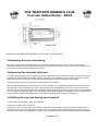
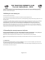
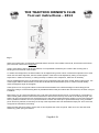
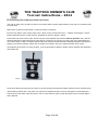
THE TRACTION OWNER’S CLUB Tool set instructions - 2012 The tool sets should enable the following maintenance to be carried out on a 4-cylinder Traction: Remove and refit a front hub/brake drum. Remove and refit wheel bearings and seals. Remove and refit driveshafts. Fit and centralise brake shoes. Remove and refit upper and lower suspension/steering joints. Disconnect track-rod joints. Remove the steering wheel from its column. Remove waterpump and dynamo pulleys, battery terminals, clutch lever, differential bearings, etc from their shafts. Remove the rear torsion bars from their mountings. Use of the TOC tool sets Use of these tools on the Citroen Traction was originally intended to be a professional operation, but will often now be carried out by enthusiastic amateurs, so please take care at all times for your own safety and the care of the tools. The size of the tools, forces involved, dismantling weight-bearing parts of the car and risk of damage mean that great care should be taken to use them sensibly, within your limits and theirs, seeking help where necessary. Correct size, well-fitting spanners or sockets must be used to prevent damage to the tools or the user. ‘Surface drive’ spanners and sockets should give less risk of damage, if they are available. The tools should be carefully inspected before use to ensure that they are not damaged or are likely to be unsafe. Do not use any that appear damaged. Puller threads should be clean and oiled before use. The car and suspension units should be well supported on stands or blocks, which will not break or slip under load. The handbrake must be on and the car wheels chocked, unless the work necessitates otherwise. Any damage to the tools should be reported to the TOC custodian. DISCLAIMER It is the responsibility of the user to inspect the tools before use and to report excessive wear or damage to the TOC custodian. The Traction Owner’s club accepts no responsibility for any injury or damage resulting from the use, or misuse of the tools in this set. Use of the tools is referenced to the appropriate Operation Number as described in the Citroen Front Wheel Drive repair manual from 1938 [reprinted 1958]. Users should refer to these Operations for further guidance. A copy of the “Citroen Front Wheel Drive repair manual from 1938 [reprinted 1958]” is available in the “Members Only” Section of the TOC website Page 1 of 13 THE TRACTION OWNER’S CLUB Tool set instructions - 2012 1. Removing/fitting the front hub/brake drum. Operation 120 Items you will need: Mechanics tool set, jack, axle stand or suitable wood blocks, hub puller [1750T + 1820T, torque wrench [30mkg minimum], split pins, 38mm socket and driver A] Removing hub Before removing the brake drum, the brake adjusters should be fully slackened off. The hub must be prevented from rotating whilst the hub nut is being undone. With open-centre wheels, e.g. Slough type, this can be done with the wheel still fitted and the tyre on the floor. If the wheel has a centre bar, e.g. LHD type, remove the wheel and fit the drum locking bar onto the wheel studs. Replace some wheel nuts to retain it. [Some owners with centre-bar wheels, keep an old open-centre wheel to fit for this operation, as it is the easiest method of resisting rotation] Remove the split-pin from the hub nut. Important note: Hub nuts have either right or left-hand threads. The driveshafts on a Traction are ‘handed’, but it is possible to fit them to either side of the car. When assembled correctly, the left one [UK “nearside” position] has a normal [clockwise-to-tighten] thread and the right one [UK “offside” position] has a left-hand [anticlockwise-to-tighten] thread. This is to ensure that they stay tight during forward motion. SOME CARS ARE FITTED WITH ‘INCORRECTLY HANDED’ DRIVESHAFTS. If you are not certain about what type is fitted, then the thread direction must be checked before proceeding, as there is a risk that the nut could be tightened further, rather than loosened. To check if a driveshaft has been fitted correctly, it is necessary to trace the direction of the short thread which protrudes from the hub nut. Using a finger nail or scriber, trace the thread to determine which direction is needed to remove the nut from the shaft. Once you are absolutely certain, use the 38mm socket to undo it, but do not remove it entirely yet. [This is not as shown in the Citroen diagram below!!] Fit the extractor body and collets to the flange of the hub as shown in Figure 1. Ensure the tip of the thread pushes on the end of the driveshaft inside the hub nut. Fit the clamp ring round the collets. The construction of some pullers may not allow the nut to be retained on the shaft thread, in which case it will have to be removed completely. Experience shows that if a high force is needed to break the taper joint, then the split-pin holes through the end of the shaft can be flattened by the force of the puller screw, preventing the split pin being refitted later. To avoid this, it is advised to put a short length of wire or a nail in the holes, or a suitable hard thrust pad on the end of the shaft, so that the holes are not closed by the force. Using the 27mm socket and sliding T-bar [no pipe wrenches please, as they will damage the nut] tighten the puller screw as much as possible, and the hub may release. If not, remove the socket and using the copper mallet only, hit Page 2 of 13 THE TRACTION OWNER’S CLUB Tool set instructions - 2012 the nut of the puller very hard along the axis of the thread as shown below in Figure 1. The hub/drum/puller combination should separate from the taper of the driveshaft and be retained by the hub nut. Fig. 1 Direction of mallet strike ---------------------------------- In line with thread axis If the hub nut is removed first, there is a risk that the whole, heavy assembly could fly completely off the shaft and damage itself or you! If the first attempt does not release the hub, further tightening + hammering should do so. If this fails, try hammering hard simultaneously on both sides of the coned part of the hub whilst under puller tension. When the hub is released, remove the nut, puller and if it is still attached, the wheel. B] Refitting the hub/brake drum Key points are: Check the condition of tapers on the hub and driveshaft. These should be smooth and free of damage. Note that the hub has only two short lengths of taper, at each end, but the shaft has a continuous taper. Any slight damage to the central area of the shaft taper is therefore unlikely to cause a problem. Also check that the shaft and nut threads are good. Ensure the nut can be screwed on by hand first. Clean/degrease the tapers on both hub and driveshaft [Citroen recommend alcohol], but do not oil or grease them. Check that the Woodruff key and its socket are not damaged. Ensure that the key ‘bottoms’ in its socket when refitted to the shaft. Its straight edge should be aligned with the taper of the driveshaft to allow the hub to slide on easily. Ensure the keyway in the hub is aligned with the key in the shaft and refit the drum by hand, until it is almost fully home. If this is not possible, then remove and check for obstructions. It could be that the key has become dislodged. With the hub hand-fitted, look for the key in the hub keyway[with the hub nut removed]. If it cannot be seen, try poking a stiff wire into the slot. If the wire passes more than 10 mm into the drum, the key has been displaced and the hub must be removed to replace it. Failure to do this is likely to cause irreparable damage to the taper of both the shaft and drum. Screw on the hub nut by hand when it is satisfactory. The face and thread of the hub nut should be lightly oiled before tightening. It must be very tight [Citroen specify a minimum torque of 30mkg / 216 ft-lbs *], with the final tightening operation made in one smooth turn**. [Note that Citroen originally specified the use of a 1metre long spanner [1810T] for this job, which will give some idea of what is Page 3 of 13 THE TRACTION OWNER’S CLUB Tool set instructions - 2012 required]. If the split-pin holes in the nut and driveshaft still need to be aligned, preferably tighten further, but if necessary, slightly reverse the nut to achieve this. Always use a new split-pin. * It is recommended that a simple torque wrench is acquired for this job. Suitable examples with ¾” drive and adequate torque range are Draper 3005A or Sealey AK228. **The tightening operation can be restricted by the front wing if the wheels are aligned straight ahead. Therefore it might be easier to do this by first turning the wheels at an angle, so that you work outside the wing edge. 2. Removing/ refitting the outer hub bearing A] Removing Items you will need: Mechanics tools, axle stand or suitable blocks, puller with bearing collets [1819T], ring nut spanner [1825T]. Remove the hub first as in 1, above. Secure the lower suspension arm on a suitable block or stand. Remove the securing tab and large ring nut + seal from the hub. [Both hubs have normal thread direction] The correct castellated spanner, 1825T, should always be used for this job. Other methods may work, but are likely to leave the nut damaged. Fit the bearing collets to the puller body used to remove the hub in operation 1 and engage these fully in the bearing groove, with the clamp ring loose. Tension the puller by hand first, then rotate the collets to ensure that they are properly seated in the groove. Tighten the clamp ring to ensure they cannot spread. [The puller flange is easily damaged if not tight in the groove]. Use the puller to extract the bearing from the hub and driveshaft [Figure 2]. It is not necessary to hammer the puller nut with the copper mallet, as there is no taper to break. Fig.2 B] Refitting Page 4 of 13 THE TRACTION OWNER’S CLUB Tool set instructions - 2012 This should be the reverse of removing it. Using a suitable piece of soft tubing e.g. brass or aluminium as a drift on the inner race, hammer the bearing back into the hub. Take care not to damage the ball-race. When fully home, the puller groove should be level with the edge of the hub. 3. Removing the inner hub nut. This is fitted against the inner bearing behind the bearing spacer and a ‘wad’ of grease. Items you will need: Mechanics tools, special castellated spanner [1826T], new tab washer [TOC part no K13], Torch or lamp, 45mm deep socket, driveshaft lock [1830T] Complete operation 2a first. Using a suitable tool, clean out as much of the grease as possible. Remove the bearing spacer, which is a firm sliding fit in the bore of the hub, using a suitable tool, e.g. bent wire, There is a split along one side of the spacer, which can assist in removing it. Remove any more grease that is possible. Using a small probe, locate the edge of the tab washer which is turned up against one of the flats of the nut. The torch might be useful for this. Punch the tab down flat against the bearing behind it. Fit the special spanner, 1826T, onto the castellated nut. Replace the outer hub nut and screw it up to the end of the spanner, but not tightly. [Figure 3] This is most important, because these nuts can be very tight and a lot of force may be needed to release the nut. If the hub nut is not used to hold the spanner on, there is a risk that the spanner will ‘cam off’ [i.e. disengage due to angularity on the nut or the driving end of the spanner]. This can cause damage to both nut and spanner and might make it impossible to complete this job in the normal way. The rotation of the inner nut is the same as for the outer hub nut, i.e. right or left-hand thread. The shock absorber needs to be removed, or at least the lower end loosened and swung upwards, before the next stage can be done. Clamp the driveshaft lock [1830T] tightly round the driveshaft so that it contacts the front of the lower suspension arm. To ensure it does not slip, it is possible to wrap a strip of medium-grade abrasive cloth round the driveshaft, folded so that an abrasive face is in contact with both driveshaft and the clamp jaws. Tighten the bolts. Fit the 45mm extra deep socket over the hub nut to engage with the hexagon of the special spanner, [1826T, below] and undo the nut in the correct direction. This can be very tight. Fig.3 Page 5 of 13 THE TRACTION OWNER’S CLUB Tool set instructions - 2012 Remove the nut and the tab washer behind it. Clean out any remaining grease. 3a Removing the inner hub bearing Although no special tool is needed for this, it is worth knowing here that this can only be done by removing the driveshaft from the hub and knocking the bearing out from the inner end of the hub unit. There are two ‘cutouts’ in the hub, behind the inner seal which allow this to be done. 3b Removing the driveshaft /stub-axle To remove the driveshaft, the lower steering joint must be dismantled [4] to allow the hub unit to be swung out enough to disconnect the driveshaft at its splined coupling. [Obviously, if the gearbox unit is not in place, there is no need to dismantle the lower steering joint to remove the driveshaft.] Disconnect the driveshaft at this coupling. The driveshaft is pushed out of the bearing in the direction of the gearbox. Fit the castellated outer ring nut back onto the hub unit, hand-tight only. Assemble the puller unit from the red ‘Clarke’ case with the ‘hooked’ legs fitted to the yoke. Hook the legs onto the castellations of the ring nut and use the thrust screw to push the driveshaft from the inner hub bearing [17mm spanner]. Ensure that the leg nuts are very tight before use, or the legs may splay and slip off. If the castellated nut has been damaged, it is possible to fit the collet clamp ring round the hub unit, behind the damaged ring nut and attach the puller hooks to this for a better grip. 3c Refitting the inner hub bearing and driveshaft If a new seal is to be fitted, it is worth doing that first. Push the inner bearing into the hub unit. Push the stub axle of the driveshaft into the bore of the bearing. The bearing inner race should be a tight fit on the driveshaft, but the outer race less tight in the bore of the hub. Sufficient thread should protrude to allow the inner hub nut to be used to pull the driveshaft fully into place. If not, the bearing may have to be hammered down the driveshaft Page 6 of 13 THE TRACTION OWNER’S CLUB Tool set instructions - 2012 until the nut can engage with the thread. Note that this will probably require the use of an assistant and a soft, e.g. aluminium, tubular drift which bears on the inner bearing race, not the outer one. Take care not to damage the seal, ball-race or thread when doing this. 3d Refitting the inner bearing nut This is the reverse of the removal. The driveshaft lock should be fitted to contact the rear side of the lower suspension arm. Again, the spanner should be held in place with the hub nut whilst tightening [10mkg/72 ft-lbs torque]. Always use a new tab washer here. To minimize any possible damage or distortion to the tab washer as the nut is tightened in a ‘blind’ hole, it is advisable to first tighten the nut on to the driveshaft to the specified torque, without the tab washer, to fully position the bearing/driveshaft. Then remove the nut, fit the tab washer and finally retighten the nut again to the torque setting. Ensure that the washer tab engages well in the driveshaft slot, before fitting the nut. It can be helpful to slightly ‘prebend’ the outer tabs of the washer before fitting the nut, as this allows the chosen bending tool [eg. old screwdriver] to engage with the washer edge more easily for the final tab bending. 4. Dismantling the steering/suspension ball joints. Items you will need: Mechanics tools, jack, stands and blocks, split pins, special breakers - lower [1851T] and top [1850T]. 24mm and 33mm ring spanner or socket. Patience and possibly some help. Remove the wheel and support the lower suspension arm on a stand about half way along its length. The arm must be supported high enough to allow fitting of the lower breaker tool and use of a hammer on the thrust bolt. A. LOWER JOINT Remove the cap [3 bolts] and split-pin. Loosen the castellated nut, but do not remove completely. [This tends to be a very stiff thread, which is normal. It does not indicate damage]. The joint may be fitted with the original shim adjustment system or the optional spring cup adjusters [TOC Part no.H4]. Fit the breaker tool as shown in Figure 4 Page 7 of 13 THE TRACTION OWNER’S CLUB Tool set instructions - 2012 Fig. 4 When using these tools, it is absolutely essential that the axis line of the breaker’s thread, B, and the axis of the swivel pins of the hub unit all form a straight line. If this is not achieved, then it will be very difficult, if not impossible to break the joint. There is also a strong risk of bending the screw thread of the breaker. To achieve this straight axis, the lower breaker can be aligned using screw A which contacts the suspension arm. If this alone cannot achieve alignment, then the relative position of the hub must be adjusted by raising or lowering the suspension in relation to the body, or raising the body in relation to the suspension, whichever is necessary. Having established alignment, the breaker thread, B can be tightened using the 33mm socket. When under tension, use of the copper mallet on the bolt head, in line with the thread axis should break the joint. If it does not break readily, check the alignment again and retighten. These joints can be very tight and there is some risk that the breaker tool could be damaged. If this is likely [and for emergency uses], it is worth knowing that it is possible break the lower joint without the use of the tool, as shown in Figs 5 & 6 below: Remove the cap, any shims and bearing cone under the lower ball and loosen the nut on the swivel pin. The leather or rubber swivel gaiter must be unwired and turned back to allow access to the top of the ball on the swivel pin taper. The entire hub must now be lowered onto something firm (an axle stand is ideal) until all the weight is on the lower swivel pin, and no possible movement can occur (work the bottom nut down the swivel pin to protect the thread). Using a suitable punch and heavy hammer, knock firmly on the top of the suspension ball. This will break the taper joint. Once it is loose, re-support the axle before proceeding. When the taper has been broken, remove the nut and separate the cones and joints. Take care not to lose the small feather key, gaiter spring and washer. Page 8 of 13 THE TRACTION OWNER’S CLUB Tool set instructions - 2012 Fig. 5 Joint complete Fig.6 Ball removal B. TOP JOINT Flatten the locking washer and using the upper joint adjusting spanners [1852T], loosen the locknut with the outer spanner. Then remove the ‘plug nut’ using the inner spanner. Remove the split pin and loosen the locknut inside the cavity. Page 9 of 13 THE TRACTION OWNER’S CLUB Tool set instructions - 2012 Experience shows that both the locknut and plug nut are likely to have been damaged by previous attempts to remove them without the correct tools. If there is any damage to the flats of the locknut or the slots of the plug, these should be corrected with a file, before 1852T is used. The plug slots must be square and vertical or the inner spanner will slip and cause more damage. Again, ensuring the suspension joint and breaker tool [1850T] are aligned, tension the breaker using the 24mm socket and break with the copper mallet if needed. Refitting the joints This is the reverse procedure and can be quite ‘fiddly’ with the lower joint. There is a high risk of trapping fingers, so some help may be worthwhile. Always check and refit the feather keys, gaiter springs/washers and new split pins. Before refitting the ball joints it is worth checking their condition, based on the recommendations in the workshop manual. 5. Dismantling the steering Operation 123 Items you will need: Mechanics tool set, jack, axle stand or wood blocks, steering joint breaker [1964T], steering wheel extractor [1950T], possibly new joint covers [TOC F1, 1a, F2, F45]. A] Breaking the track-rod joints. Wheel end - Remove the split pin and loosen the castellated nut, but do not remove it completely. Fit the breaker tool 1964T on the steering arm as shown in Fig.7 below, with the screw inside the nut and tighten the screw. The joint may break immediately, but if not, try increasing the tension and hitting the top of the screw with the copper mallet, whilst simultaneously holding a large hammer under the track rod end, or supporting it rigidly. When the joint has broken, the nut can be removed to release the track rod. It is likely that the ball joint cover between the steering arm and the track rod end will be damaged by this operation, because there is so little space to insert the breaker jaw. Be prepared to reshape the damaged cover or to fit a new one when re-assembling. Steering rack end - The same tool can be used to remove the track rod from the steering rack. Fig.7 Page 10 of 13 THE TRACTION OWNER’S CLUB Tool set instructions - 2012 B] Removing the steering wheel and boss. This can be ‘fiddly’ job to do with one person and several bolts to adjust single-handed, so the help of an assistant may be useful here. Remove the centre trim of the wheel*. Loosen the centre nut [32mm]. From the red ‘Clarke’ case, use the puller yoke + thrust screw+ pointed thrust end + 2 plastic covered legs + 2 black bearing separator halves + rubber cushion. Assemble as shown in Figure 8, below. Screw the thrust screw into the yoke. Screw a leg into each separator half, with the flat side upwards. Then, with the separator below the wheel boss and the yoke above it, put the top of a leg into one slot of the yoke. Hand-tighten the nut so that it does nut slip out. Repeat with the other half. Fit the bolts that hold both separators together and adjust so that they fit round the steering column and are square and central in the yoke. Tighten the bolts when correct. If the steering wheel boss is in good condition, it can be protected by fitting the rubber cushion between the separators and wheel boss. Fig. 8 Screw down the thrust screw into the centre nut [17mm spanner] until the joint breaks. Remove the nut, wheel and key. *Some steering wheels are a one-piece unit, others have separate bosses. If the rim and spokes are separated first from the boss, mark which bolt holes were in use to connect the two parts, so that the wheel can be correctly aligned when replaced. Page 11 of 13 THE TRACTION OWNER’S CLUB Tool set instructions - 2012 6. Dismantling the rear torsion bars Operation 127 Items you will need: Mechanics tool set, jack, axle stand or wood block, rear torsion bar removal clamp [MR 1578] [This is the same tool used as the driveshaft lock, 1830T] Operation 127 in the Citroen repair manual adequately describes the dismantling and replacement of the torsion bars, so no further descriptions are needed here. 7. Centralising the brake shoes – front and rear Operation 120 Items you will need: Mechanics tool set, jack, axle stand or wood block, brake shoe centralizer - 2100T/2103T Once the new brake shoes have been fitted to the back plates, they must be centralized to ensure that their wear is even. A] FRONT SHOES At this point do not fit the nuts for the lower [internal] adjusters. Set all 4 adjusters inwards, so that the shoes are not likely to contact the drum, when it is replaced. Replace the hub/drum on the driveshaft, without the key and just push it on firmly by hand. Rotate the front shoe adjuster [17mm, on the rear of the backplate], so that the shoe just contacts the drum when it is rotated by hand. Without moving any of the adjusters, pull the drum off the driveshaft. The ‘highest’ point, where the drum contacted the shoe will be the reference point. Fit the centralising tool onto the driveshaft by clamping it tightly into the ‘V’ of the tool with the cross bar and wing nuts. Adjust the reference plate to just touch the front shoe at the reference point and tighten the lock nuts – figure 9. Fig. 9 Page 12 of 13 THE TRACTION OWNER’S CLUB Tool set instructions - 2012 Now rotate the driveshaft and plate by hand to the lower end of the front shoe and adjust the eccentric bush there, so that this end of the shoe also touches the plate. Rotate further to the lower end of the rear shoe and adjust. Finish at the top end of this shoe. Finally, go all the way round again to check that they are still all correct. When adjusted, remove the tool and fit the lower nuts and split pins. Set the top adjusters inwards, so that the hub/drum can be fitted. After fitting, reset the top adjusters. B] REAR SHOES It is worth noting that when new linings have been fitted to rear shoes, it is usually necessary to slacken off the handbrake adjusters to allow the thicker shoes to clear the inside of the brake drum. The procedure is the same as for the front shoes, except that to find the reference point, it will be necessary to hold the hub/drum on the axle with the centre nut just temporarily fitted. Also, the centralising tool is not clamped tightly onto the axle shaft; it should be able to slide round the shaft with hand pressure. 8. Other uses The contents of the red ‘Clarke’ case can be assembled in a number of configurations which will allow additional jobs to be done, e.g. removing waterpump and dynamo pulleys, battery terminals, clutch lever, differential bearings, etc from their shafts. These will require the choice of ‘hook’ legs or separator, as required. Some items in the case have no apparent use on a Traction. ******************************************************************************** Tony Hodgekiss 2012 Page 13 of 13


![Le forum des Citroën-compactes :: Voir le sujet - [ZX] Change](http://vs1.manualzilla.com/store/data/006464864_1-2c2d5459abd3718094b0344e801cc758-150x150.png)