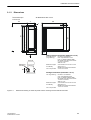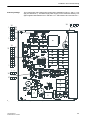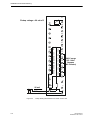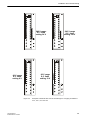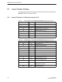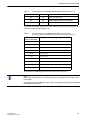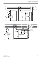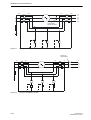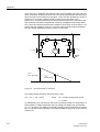
1
SIPROTEC 7VH60 V1.0 High-Impedance Differential Relay C53000-B1176-C136-3 Introduction Hardware and Connections SIPROTEC High-Impedance Differential Relay 7VH60 V1.0 Manual C53000-B1176-C136-3 Initial Inspection Installation and Commissioning Maintenance and Troubleshooting Technical Data Appendix 1 2 3 4 5 6 A Exclusion of liability We have checked the contents of this publication and every effort has been made to ensure that the descriptions of both hardware and software are as accurate as possible. However, deviations from the description cannot be completely ruled out, so that no liability can be accepted for any errors or ommissions contained in the information given. The data in this manual are checked regularly and the necessary corrections are included in subsequent editions. We are grateful for any improvements that you care to suggest. Subject to technical modifications without notice. 1.00.01 Siemens Aktiengesellschaft Copyright Copyright Siemens AG 2003 All Rights Reserved It is prohibited to pass on or copy this document or to use or disclose its contents without our express permission. Any duplication is a violation of the law and subject to criminal and civil penalties. All rights reserved, particularly in the event of a patentaward or utility model registration. Registered trademarks SIPROTEC® and DIGSI® are registered trademarks of the SIEMENS AG. The other names appearing in this manual may be trade names the use of which by third parties for their own purposes may infringe the rights of the owners. C53000-B1176-C136-3 Preface Purpose of This Manual This manual describes the functions, operation, installation, and commissioning procedure of the device. In particular, the following: • Description of hardware and connections → Chapter 2. • Descriptions of device functions and settings → Chapter 4. • Instructions for mounting and commissioning → Chapter 4. • Compilation of technical specifications → Chapter 6. • Ordering code and setting advice → Appendix A Targeted reader Protection engineers, commissioning engineers, personnel responsible for setting, testing, checking, and maintenance of protection equipment, automation and control equipment, and electrical utility and power plant personnel. Applicability of This Manual This manual is valid for SIPROTEC® 7VH60 High-Impedance Differential Relay. Indication of Conformity This product complies with the directive of the Council of the European Communities on the approximation of the laws of the member states relating to electromagnetic compatibility (EMC Council Directive 89/336/EEC) and concerning electrical equipment for use within certain voltage limits (Low-voltage Directive 73/23/EEC). This conformity is proved by tests conducted by Siemens AG in accordance with Article 10 of the Council Directive in agreement with the generic standards EN 50081 and EN 61000-6-2 for EMC directive, and with the standards EN 60255–6 for the lowvoltage directive. The product conforms with international standards of series IEC 60255 and the German standard VDE 0435. Additional Support For additional support regarding SIPROTEC® devices, please contact your Siemens representative. This product is UL-certified to Standard UL 508 File No.: E194016 IND. CONT. EQ. 69CA Type 1 if mounted into a door or front cover of an enclosure 7VH60 Manual C53000-B1176-C136-3 i Preface Instructions and Warnings The following notes and standard definitions are used: DANGER means that death, severe personal injury, or considerable equipment damage will occur if safety precautions are disregarded. WARNING means that death, severe personal injury, or considerable equipment damage could occur if safety precautions are disregarded. Caution means that light personal injury or equipment damage may occur if safety precautions are disregarded. This particularly applies to damage to the device and to resulting damage of the protected equipment. Instruction is an important piece of information regarding the product or a part of the manual that deserves special attention. Warning! During operation of electrical equipment, certain parts of these devices are under high voltage. Severe personal injury or significant equipment damage could result from improper behavior. Only qualified personnel should work on this equipment or in the vicinity of this equipment. This personnel must be familiar with all warnings and service procedures described in this manual, as well as with safety regulations. Prerequisites for proper and safe operation of this product are proper transport, storage, setup, installation, operation, and maintenance of the product, as well as careful operation and servicing of the device within the scope of the warnings and instructions of this manual. In particular, the general instructions and safety regulations for work with high-voltage equipment (e.g. ANSI, IEC, EN, or other national or international regulations) must be observed. Noncompliance may result in death, injury, or significant equipment damage. QUALIFIED PERSONNEL Where this manual refers to qualified personnel in connection with instructions and advice regarding safety precautions such qualified personnel are those persons that are qualified to prepare, install, commission, and operate this device, and who possess the following qualifications: ii q Trained and instructed (or other qualification) in the switching, grounding, and operation of high voltage switchgear and systems. q Trained and instructed in accordance with safety standards relating the application of appropriate safety equipment. q First aid training. 7VH60 Manual C53000-B1176-C136-3 Table of Contents 1 2 3 4 Introduction....................................................................................................................................... 1-1 1.1 Mode of Operation............................................................................................................... 1-1 1.2 Features .............................................................................................................................. 1-3 1.3 Application Examples .......................................................................................................... 1-4 Hardware and Connections ............................................................................................................. 2-1 2.1 Versions of the 7VH60 High-Impedance Differential Relay................................................. 2-1 2.1.1 Construction ........................................................................................................................ 2-1 2.1.2 Dimensions.......................................................................................................................... 2-3 2.2 Varistor/Surge Arrester........................................................................................................ 2-6 Initial Inspection ............................................................................................................................... 3-1 3.1 Unpacking and Packing....................................................................................................... 3-1 3.2 Inspection Upon Receipt ..................................................................................................... 3-1 3.2.1 Electrical Check................................................................................................................... 3-1 3.3 Storage ................................................................................................................................ 3-2 Installation and Commissioning ..................................................................................................... 4-1 4.1 Installation and Connections ............................................................................................... 4-1 4.2 Jumper Position Settings..................................................................................................... 4-6 4.2.1 Jumper Positions for Setting Increments of 6V ................................................................... 4-6 4.2.2 Jumper Positions for Setting Increments of 24V ................................................................. 4-8 4.3 Preparation for Commissioning ......................................................................................... 4-10 4.4 Testing and Commissioning .............................................................................................. 4-13 4.4.1 4.4.1.1 4.4.1.2 Commissioning Tests ........................................................................................................ 4-14 Secondary Injection Testing .............................................................................................. 4-14 Primary Injection Testing ................................................................................................... 4-15 4.4.2 Functional Test of 7VH600*-0*A10-0AA0.......................................................................... 4-18 4.4.3 Functional Test of 7VH600*-0*A20-1AA0.......................................................................... 4-19 4.5 Final Preparation of the Device ......................................................................................... 4-23 7VH60 Manual C53000-B1176-C136-3 iii 5 6 A iv Maintenance and Troubleshooting ................................................................................................. 5-1 5.1 Troubleshooting ................................................................................................................... 5-1 5.1.1 Replacing the Power Supply Fuse....................................................................................... 5-1 5.2 Return .................................................................................................................................. 5-3 Technical Data................................................................................................................................... 6-1 6.1 General Device Data ........................................................................................................... 6-1 6.1.1 Inputs/Outputs ..................................................................................................................... 6-1 6.1.2 Specifications....................................................................................................................... 6-5 6.1.3 Mechanical Tests................................................................................................................. 6-7 6.1.4 Climatic Stress..................................................................................................................... 6-8 6.1.5 Operating Conditions ........................................................................................................... 6-8 6.2 Mechanical Details............................................................................................................... 6-9 Appendix........................................................................................................................................... A-1 A.1 Selection and Order Data ....................................................................................................A-1 A.2 Setting Procedure ................................................................................................................A-3 A.2.1 List of Abbreviations ............................................................................................................A-3 A.2.2 Calculation of Relay Setting.................................................................................................A-4 A.3 Application Examples ..........................................................................................................A-7 7VH60 Manual C53000-B1176-C136-3 Introduction 1.1 Mode of Operation The 7VH60 relay is a single pole sensitive current monitoring relay. The a.c. input impedance of the relay is adjusted by means of resistors connected in series. The resulting relay setting is a voltage pick-up value that is set by removing short-circuit links from the rear terminals. When a short-circuit link is screwed between the terminals, the resistor is shorted out and when the short-circuit link is removed, the resistor is in circuit. Each resistor corresponds to a voltage value which is the pickup current of 20 mA multiplied with the resistor’s ohmic value. The voltage setting on the relay is determined by adding up the voltage drops accross the resistors which are not shorted out by short-circuit links (series resistors in circuit) plus a minimum base voltage setting. A maximum setting of 60 V (short-circuit links of the left side) or 240 V (shortcircuit links on the right side) is possible. On delivery, the short-circuit links are not installed. The input from the CTs is connected to terminals 1 and 2. The sensitive relay input transformer galvanically isolates the static measurement circuit of the relay from the main current transformers. The AC measured current is band pass filtered and rectified resulting in a dc voltage proportional to the input signal. This voltage is monitored by a Schmitt trigger circuit. If it exceeds the d.c. voltage that is equivalent to the relay nominal operating current of 20 mA, the trigger operates to energize the command output relay as well as the operation indicator. The auxiliary supply is connected to terminals 30 and 31. An auxiliary supply monitoring circuit consisting of a green LED and a N/C relay contact is provided to indicate the status of the supply. The relatively simple electronic design of the 7VH60 provides a robust and reliable relay suitable for all high impedance circulating current protection applications. The use of solid state measuring circuits ensures constant and fast operating times. Optionally, the relay is available with a bus wire supervision feature. If during operation a differential current is detected which is above the supervision pickup threshold but below the relay pickup voltage, the differential protection is blocked after a set time. The bus wire supervision pickup threshold is settable by means of jumpers. Likewise, the delay time for pickup of the supervision can be set by jumpers in a range of between 1 s and 10 s. Warning! You have to connect the varistor/surge arrester to the 7VH60 before switching the device on. Any operation without varistor/surge arrester may destroy the device. 7VH60 Manual C53000-B1176-C136-3 1-1 Introduction Jumper X51 Position 24 V: increments of 24 V Jumper X51 Position 6 V: increments of 6 V 1 2 X51 Short-circuit link X2_1-2: Relay latched Short-circuit link X2_2-3: Relay not latched 6V >I 24 V 1K2 7 9 X2 1K2 11 1 X12_2-3 LED 1 1K2 13 K1 1K2 15 6K 17 Jumper X15: 1-2 internal blocking disabled 1K2 X15_2-3 8 X15_1-2 LED 4 300R 10 300R 12 300R 14 Optional: bus wire supervision, settable with X5, and pickup time settable with X9 300R 300R 16 LED 2 1K5 K4 18 19 X6_1-2 Binary input External reset 20 LED 3 22 Reset K1 23 21 X7_1-2 + 30 Optional Binary input Blocking Diff. function X8_1-2 Blocking 24 X8_2-3 Inverted blocking 25 26 24V-250V dc 80V-264 V ac K1 K4 27 L Uh N 31 28 24V; 5V K2 29 _ K2 LED1 Trip stored LED2 Buswire alarm (option) LED3 Trip blocked by external signal (option) LED4 Trip not stored Figure 1-1 1-2 LED Service LED Blocked K1 Trip K2 Supply fail K4 Buswire alarm Schematic Diagram of the 7VH60 High-Impedance Differential Relay 7VH60 Manual C53000-B1176-C136-3 Introduction 1.2 Features • Robust solid state design • Filtering for inrush restraint • Auxiliary dc supply monitor • Fast operating time (15ms) • Simple voltage setting • LED indicator • Option "Buswire alarm" (supervision) • Option "Blocking input from external" 7VH60 Manual C53000-B1176-C136-3 1-3 Introduction 1.3 Application Examples A B C L1 L2 L3 P1 P2 S1 22 23 24 25 1 S2 2 7VH60 P1 P2 P1 P2 S1 S2 S1 22 23 24 25 1 S2 2 7VH60 Figure 1-2 1-4 Restricted Ground Fault Protection of Power Transformer Windings 7VH60 Manual C53000-B1176-C136-3 Introduction A B C L1 L2 L3 S1 P1 P2 7VH60 S2 1 2 22 23 24 25 7VH60 1 2 22 23 24 25 7VH60 1 2 S1 22 23 24 25 P1 P2 S2 Figure 1-3 7VH60 Manual C53000-B1176-C136-3 Differential Protection of a Generator 1-5 Hardware and Connections 2.1 Versions of the 7VH60 High-Impedance Differential Relay The high-impedance differential relay SIPROTEC® 7VH60 can be supplied as a surface mounting or flush-mounting device in a sealed housing (7XP20) which takes up 1 /6 of a standard 19 inch rack. 2.1.1 Construction All the protection functions including the dc/dc converter are accommodated on a printed circuit board with double Eurocard format. This p.c.b. together with a guide plate, a multi-pin connector module and a front unit makes up a plug-in module which is installed in a 7XP20 housing. The guide plate slots and the spacers on the p.c.b. along with the shape of the connector module ensures proper mounting and securing of the module. The inside of the housing is free from enamel coating and thus provides a large contact area for the earthing tabs of the module thus ensuring good conductivity and shielding. Connection to earth is ensured before the plug connection makes. Provision is made for connection of grounding braid on the housing to ensure solid low impedance earthing of the device. The heavy-duty current plug connectors provide automatic shorting of the c.t. circuits whenever the module is withdrawn. This does not replace the precautions that are necessary when working in c.t. secondary circuits. The degree of protection for the housing is IP51, for the terminals IP21. Two different types of housing can be supplied: • 7VH600*-*B*** in housing 7XP20 for panel surface mounting The housing consists of a metal tube and terminal block and has four holes for securing the relay to the panel. All external signals are connected via the terminal block which is secured at the rear of the housing. For each electrical connection, one screw terminal for the connection of up to two ring cable lugs is provided. Alternatively, up to two solid bare wires (also of different diameter) can be connected directly. Use copper conductors only! For dimensions, see Figure 2-1. 7VH60 Manual C53000-B1176-C136-3 2-1 Hardware and Connections • 7VH600*-*E*** in housing 7XP20 for panel flush mounting or cubicle mounting The housing consists of a metal tube with fixed angle brackets for securing into the panel cut-out or into the cubicle rack. All external signals are connected via the terminal block which is secured to the rear of the housing. For each electrical connection, one screw terminal for the connection of up to two ring cable lugs is provided. Alternatively, up to two solid bare wires (also of different diameter) can be connected directly. Use copper conductors only! Figures 2-1 and 2-2 show the dimensions of the available housing types. 2-2 7VH60 Manual C53000-B1176-C136-3 Hardware and Connections 2.1.2 Dimensions All dimensions are in mm. Recommended space to the next unit 77 180 260 29.5 9 31 266 300 280 30 8 5 3 1 7 6 4 2 100 55 Heavy current connectors (terminals 1 to 6) Screwed terminal (ring cable lug): for bolts 6 mm diameter max. major diameter 13 mm type: e.g. PIDG of Messrs AMP for copper wires with cross-section 2.7 mm2 to 6.6 mm2 AWG 12 to 10 Solid bare copper wire directly: cross-section 2.5 mm2 to 4.0 mm2 AWG 13 to 11 flexible wire requires end sleeves 3.5 Nm or 34 in-lbs View A 20 Earthing screws max. torque value Voltage connectors (terminals 7 to 31) Isol. ring cable lug for bolts 4 mm diameter max. major diameter 9 mm type: e.g. PIDG of Messrs AMP for copper wires with cross-section 1.0 mm2 to 2.6 mm2 AWG 17 to 13 Solid bare copper wire directly: cross-section 0.5 mm2 to 2.6 mm2 AWG 20 to 13 flexible wire requires end sleeves 1.8 Nm or 16 in-lbs max. torque value Figure 2-1 Dimensional drawing of 7XP20 for panel surface mounting with terminals at both sides 7VH60 Manual C53000-B1176-C136-3 2-3 Hardware and Connections All dimensions are in mm. 29.5 172 37 75 70 266 244 Mounting plate 71 +2 Connector terminals Heavy current connectors (terminals 1 to 6) Screwed terminal (ring cable lug): 245 255.8 +1 ± 0.3 5 or M4 max. torque value for bolts 6 mm diameter max. major diameter 13 mm type: e.g. PIDG of Messrs AMP for copper wires with cross-section 2.7 mm2 to 6.6 mm2 AWG 12 to 10 3.5 Nm or 34 in-lbs Voltage connectors (terminals 7 to 31) Isol. ring cable lug 5.4 6 7.3 Figure 2-2 2-4 56.5 -± 0.3 Panel cutout max. torque value for bolts 4 mm diameter max. major diameter 9 mm type: e.g. PIDG of Messrs AMP for copper wires with cross-section 1.0 mm2 to 2.6 mm2 AWG 17 to 13 1.8 Nm or 16 in-lbs Dimensional drawing of 7XP20 for panel flush mounting or cubicle mounting 7VH60 Manual C53000-B1176-C136-3 Hardware and Connections The front panel bears the following operating and indication elements: 1. Reset Key This key is used to reset the latched LED 1 and the latched contacts. 2. LEDs 4 LEDs with fixed assignment are provided for indication. The function assigned to the LEDs is marked on the front panel. 3. Device Status Indicators The two LEDs “RUN” (green) and “ERROR” (red) indicate the operating condition of the device. 4. Covers for the screws that secure the front panel. Front and Rear View Figure 2-3 provides a simplified view of the front and rear panel of the device with threaded (screw-type) terminals. + 30 - =/~ 28 26 31 - 29 27 25 24 23 22 21 20 18 16 19 17 15 14 13 12 11 10 9 8 7 5 6 3 4 1 2 Figure 2-3 7VH60 Manual C53000-B1176-C136-3 Rear/Front View of a 7VH60 2-5 Hardware and Connections Short-Circuit Links Short-circuit links are provided for setting the voltage pickup threshold of the 7VH60. On delivery, these short-circuit links are not installed. The short-circuit links have to be installed on the right (240 V) or left hand side (60 V) as seen from rear in the 7VH600*-*E***on the left (240 V) or right hand side (60 V) as seen from front in the 7VH600*-*B***Ordering information for the link is provided in Section A.1 of the Appendix. 2.2 Varistor/Surge Arrester Weight: 1.5 kg Figure 2-4 2-6 Varistor/Surge Arrester 7VH60 Manual C53000-B1176-C136-3 Initial Inspection 3.1 Unpacking and Packing The 7VH60 is packaged at the factory to meet the requirements of IEC 60255–21. Unpacking and packing must be done with the usual care, without using force and with the appropriate tools. A visually inspection of the device should be carried out immediately after the device is received to ensure that no mechanical damage was incurred during transport. The packaging used for shipping can be reused in the same manner for further shipment. Storage packaging alone, for individual devices, is not sufficient for shipping. If other packaging is used, shock requirements under IEC 60255–21–1 Class 2 and IEC 60255–21–2 Class 1 must be met. The device should be placed in its final operating environment for a minimum of two hours before the power is applied to it for the first time. This time allows the device to attain a temperature equilibrium, and avoids the formation of moisture and condensation. 3.2 Inspection Upon Receipt 3.2.1 Electrical Check The operating conditions must comply with VDE 0100/5.73 and VDE 0105 Part 1/ 7.83, or other suitable national or international standard. Before applying the power supply voltage or measuring inputs for the first time, make sure that the device has been in the operating environment for at least two hours. This time period allows the device to attain a temperature equilibrium, and avoids the formation of moisture and condensation. Warning! The following inspection steps are done in the presence of dangerous voltages. Only appropriately qualified personnel familiar with and adhering to relevant safety requirements and precautionary measures shall perform these steps. 7VH60 Manual C53000-B1176-C136-3 3-1 Initial Inspection Power-Up 3.3 The first step consists of checking that the grounding (earthing) is securely and correctly installed. Thereafter the power supply input (auxiliary voltage) can be applied. o Connect the ground of the device to the ground of the panel/cubicle. The ground of a 7VH60 flush-mounting version is on the back plate. The ground of the version for surface-mounting is on the terminal with the ground symbol. o With the auxiliary supply disconnected (e.g. with test switches, fuses, or miniature circuit breakers), install/check the connections to the power supply input. Verify that the power supply voltage has the correct operating range. Check the polarity of the connections to the device. Adhere to the appropriate connection diagram (see Figure 1-1). o Connect the auxiliary supply (e.g. with test switches, fuses, or miniature circuit breakers) to apply power to the device. o The green LED on the front panel must light after no more than 0.5 second, and the red LED must be off. Storage If the device is to be stored, please note: SIPROTEC® devices and associated assemblies should be stored in a dry and clean environment, and within the temperature range –25 °C to +55 °C (-12 °F to +130 °F). Refer to Sub-section 6.1.4 under Technical Data. To avoid premature aging of the electrolyte capacitors in the power supply, a temperature range of +10 °C to +35 °C (+50 °F to +95 °F) is recommended for storage. The relative humidity must not lead to condensation or ice buildup. During extended storage, the power supply of the device should be energized periodically. Approximately once every two years for a period of one or two days is sufficient to regenerate the electrolytic capacitors in the power supply. This procedure should also be done prior to the device being put in-service. Under extreme climatic conditions (tropics), preheating is achieved at the same time, and condensation is prevented. After long storage, power should not be applied until the device has been in the operating environment for a minimum of two hours. This time period allows the device to attain temperature equilibrium, and avoids the formation of moisture and condensation. 3-2 7VH60 Manual C53000-B1176-C136-3 Installation and Commissioning 4.1 Installation and Connections Warning! Trouble free and safe operation of this SIPROTEC® device depends on proper transport, storage, installation, and application of the device according to the warnings in this instruction manual. Of particular importance are the general installation and safety regulations for work in a high-voltage environment (for example, ANSI, IEC, EN, DIN, or other national and international regulations.) These regulations must be observed. Failure to observe these precautions can result in death, personal injury, or severe damage to property. Requirements Verification of the 7VH60 installation according to Sub-section 4.3 and the connected external equipment must be completed. Panel Flush Mounting and Cubicle Mounting q Remove the top and bottom covers on the front cover. The covers slide out. Four elongated holes for securing the device become accessible. q Insert the device into the panel cutout or rack and fasten with four screws. Refer to Figure 2-1 in Section 2.1.1 for dimensions. q Replace the two covers. q Connect the ground on the rear plate of the device to the protective ground of the panel. Use at least one M4 screw for the device ground. The cross-sectional area of the ground wire must be greater than or equal to the cross-sectional area of any other control conductor connected to the device. Furthermore, the cross-sectional area of the ground wire must be at least 2.5 mm2 (AWG 13). q Establish connections using the screw terminals of the connector module on the housing. Always observe the designation of the individual connections and the permissible cross-sections. Section 2 has pertinent information regarding wire size, lugs, etc. 7VH60 Manual C53000-B1176-C136-3 4-1 Installation and Commissioning Panel Surface Mounting Control Voltages for Binary Inputs q Secure the device to the control panel with 4 screws. Ensure that it has sufficient clearance to the adjacent devices. For dimensional drawing, see Figure 6.2. q Connect the ground of the device to the protective ground of the panel. The crosssectional area of the ground wire must be greater than or equal to the cross-sectional area of any other control conductor connected to the device. Furthermore, the cross-sectional area of the ground wire must be at least 2.5 mm2 (AWG 13). q Establish connections using the screw terminals of the connector module on the housing. Always observe the designation of the individual connections and the permissible cross-sections. Section 2 has pertinent information regarding wire size, lugs, etc. When the device is dispatched from the factory, the binary inputs are set by jumpers to pick up with a DC control voltage of 17 V. The position of jumper X6/X7 may be changed to adjust the pickup voltage of a binary input. The jumper settings required for the different pickup voltages are shown in Section 4.2.1. Jumpers on the Printed Circuit Boards If you have to open the relay in order to change the pickup threshold of the binary inputs, proceed as follows: o The following equipment is needed: − Grounded mat for protecting components subject to damage from electrostatic discharges (ESD). − Screwdriver with a 6 mm wide tip, − #1 Phillips screwdriver, − 4.5 mm socket or nut driver. o Remove the top and bottom covers (slide off) on the front cover and loosen the screws that become accessible. o Carefully pull off the front cover. Caution! Electrostatic discharges via the component connections, the p.c.b. tracks or the connecting pins of the modules must be avoided under all circumstances by previously touching a grounded metal surface. o Check device rating 4-2 Check the jumpers according to Tables 4-1 to 4-6 and change their position if necessary. The device ratings must be checked to ensure that they match the system data. 7VH60 Manual C53000-B1176-C136-3 Installation and Commissioning Auxiliary Voltage 1 X5 The 7VH60 has a wide-range power supply that is suitable for both d.c. and a.c. voltage (see Section 6.1). The wide-range power supply can be used with auxiliary voltages supplies rated between 24 V and 250 V d.c. and between 88 V and 264 V a.c. X51 10% 20% 1 2 3 24V 6V 70% 7 X9 20 10 5 sec 11 1 L H X6 L H X7 Figure 4-1 Layout of p.c.b. showing location of the Jumpers 7VH60 Manual C53000-B1176-C136-3 4-3 Installation and Commissioning 31 Pickup voltage = 20 mA x R = =/- 30 29 27 25 23 8 1.2 k 6k 1.2 k 10 15 13 1.2 k 12 17 11 1.2 k 14 19 9 1.2 k 16 300 Ω 300 Ω 300 Ω 300 Ω 1.5 k 18 300 Ω 21 7 240 V range S.C. links (bypass the resistor) 5 6 3 20 mA CT input Figure 4-2 4-4 X51 4 1 2 Pickup Setting with Resistors and Short Circuit Links 7VH60 Manual C53000-B1176-C136-3 Installation and Commissioning 30 + = =/~ 31 - 30 + 29 28 = =/~ 27 26 26 25 25 24 24 23 23 22 22 21 21 20 20 19 19 18 18 17 17 16 16 15 15 14 13 12 11 10 9 240 V range S.C. links setting 24 V 14 13 12 11 10 9 7 7 5 5 6 6 3 3 4 4 1 1 2 2 = =/~ 31 - 30 + 29 28 29 26 25 25 24 24 23 23 22 22 21 21 20 20 19 19 18 18 17 16 15 14 13 12 11 10 60 V range S.C. links setting 18 V 17 16 15 14 13 12 11 10 9 8 9 8 7 5 7 5 6 3 6 3 4 4 1 1 2 7VH60 Manual C53000-B1176-C136-3 31 - 27 26 Figure 4-3 = =/~ 28 27 60 V range S.C. links setting 6 V 240 V range S.C. links setting 144 V 8 8 30 29 28 27 + 31 - 2 Examples of External Short Circuit Link Settings for a Tripping Threshold of 24 V, 144 V, 6 V and 18 V 4-5 Installation and Commissioning 4.2 Jumper Position Settings The following tables list the possible jumper settings and the associated meanings. Bold print indicates the delivery status. 4.2.1 Jumper Positions for Setting Increments of 6V Table 4-1 Internal Settings of the 7VH600*-0*A10-0AA0 (Setting step size of 6 V) Jumper location Position X51 2-3 Increments of 6 V X2 1-2 Tripping relay K1 latched X2 2-3 Tripping relay K1 does not latch X6 L External Reset L (> 17 V) X6 H External Reset H (> 74 V) X12 1-2 LED 4 not active (test) X12 2-3 LED 4 active (test) Table 4-2 4-6 Meaning Internal Settings of the 7VH600*-0*A10-1AA0 (Setting step size of 6 V) Jumper location Position Meaning X51 2-3 Increments of 6 V X2 1-2 Tripping relay K1 latched X2 2-3 Tripping relay K1 does not latch X5 2-20 Buswire supervision circuit (∼ 20 %) X6 L External Reset L (> 17 V) X6 H External Reset H (> 74 V) X7 L External blocking L (> 17 V) X7 H External blocking H (> 74 V) X8 1-2 External blocking normal X8 2-3 External blocking inverted X9 5-15 Delay time increment for buswire supervision (~ 5 sec.) X12 2-3 LED 4 active (test) 7VH60 Manual C53000-B1176-C136-3 Installation and Commissioning Table 4-2 Internal Settings of the 7VH600*-0*A10-1AA0 (Setting step size of 6 V) Jumper location Position Meaning X12 1-2 LED 4 not active (test) X15 2-3 Buswire supervision circuit activated X15 1-2 Buswire supervision circuit disabled To increase the voltage setting on the relay, remove the short circuit links on the connector as follows (see also Figure 4-3): Table 4-3 External Settings of the 7VH600*-0*A10-1AA0 on the Connector with a max. Tripping Threshold setting of 60 V (setting step size of 6 V) Short Circuit Links fitted on Terminals Relay setting (AC) 8-18 5.5 - 6 - 7.5 V 10-18 10 - 12 - 14 V 12-18 16 - 18 - 20 V 14-18 22 - 24 - 26 V 16-18 28 - 30 - 33 V 8-16 33 - 36 - 39 V 10-16 39 - 42 - 45 V 12-16 45 - 48 - 51 V 14-16 51 - 54 - 57 V no S.C. link 57 - 60 - 63 V The maximum settable tripping threshold is 60 V with steps of 6 V. Note: Removed jumpers that are not currently needed can be parked on the other side of the terminal. If the setting has to be modified at a later stage, the needed jumpers are then available immediately on the device. 7VH60 Manual C53000-B1176-C136-3 4-7 Installation and Commissioning 4.2.2 Jumper Positions for Setting Increments of 24V Table 4-4 Internal Settings of the 7VH600*-0*A20-0AA0 (setting step size of 24 V) Jumper location Position X51 1-2 Increments of 24 V X2 1-2 Tripping relay K1 latched X2 2-3 Tripping relay K1 does not latch X6 L External Reset L (> 17 V) X6 H External Reset H (> 74 V) X12 1-2 LED 4 not active (test) X12 2-3 LED 4 active (test) Table 4-5 Meaning Internal Settings of the 7VH600*-0*A20-1AA0 (setting step size of 24 V) Jumper Location Position Meaning X51 1-2 Increments of 24 V X2 1-2 Tripping relay K1 latched X2 2-3 Tripping relay K1 does not latch X5 2-20 Buswire supervision circuit (∼ 20 %) X6 L External Reset L (> 17 V) X6 H External Reset H (> 74 V) X7 L External blocking L (> 17 V) X7 H External blocking H (> 74 V) X8 1-2 External blocking normal X8 2-3 External blocking inverted X9 5-15 Delay time increment for buswire supervision (~ 5 sec.) X12 2-3 LED 4 active (test) X12 1-2 LED 4 not active (test) X15 2-3 Buswire supervision circuit activated X15 1-2 Buswire supervision circuit disabled To increase the voltage setting on the relay, set the short circuit links at the connector as follows (see also Figure 4-3): 4-8 7VH60 Manual C53000-B1176-C136-3 Installation and Commissioning Table 4-6 External Settings of the 7VH600*-0*A20-1AA0 at the Connector with a max. Tripping Threshold setting of 240 V (setting steps of 24 V) Short Circuit Links fitted on Terminals Relas setting (AC) 7-17 22 - 24 - 26 V 9-17 46 - 48 - 51 V 11-17 69 - 72 - 75 V 13-17 93 - 96 - 99 V 15-17 117 - 120 - 124 V 7-15 140 - 144 - 148 V 9-15 163 - 168 - 173 V 11-15 187 - 192 - 197 V 13-15 211 - 216 - 221 V no S.C. link 234 - 240 - 246 V The maximum settable tripping threshold is 240 V with steps of 24 V. Note: Removed jumpers that are not presently needed may be parked on the other side of the terminal. If the setting has to be modified at a later stage, the required jumpers are then available on the device. 7VH60 Manual C53000-B1176-C136-3 4-9 Installation and Commissioning 4.3 Preparation for Commissioning Warning! The following procedures are carried out in the presence of dangerous voltages. Therefore, only qualified personnel who are familiar with and adhere to the safety standards and precautionary measures may perform these tasks. Caution! Operating the device on a battery charger without a connected battery may result in voltages outside the allowed operating range with consequential damage or destruction of the device. For the operating limits refer to Section 6.1 under Technical Data. Carefully examine the module and housing to make sure that no damage was incurred during transit. Check that the relay serial number on the module, case and cover are identical, and that the model number and rating information are correct. Check that the external wiring is correct and in accordance with the relevant application documentation. Particular attention must be paid to the correct wiring and value of any external resistors indicated in the application wiring diagram/relay rating information. Note that shorting switches indicated in the relay diagram are located internally across the relevant terminals of the terminal block and close when the module is withdrawn. It is essential that such switches are present on all CT circuit inputs. If a test block is used, the connections must be checked in accordance with the scheme diagram, in particular the supply connections must be checked to make sure they are connected to the 'live' side of the test block. Grounding Ensure that the case grounding connection at the rear (terminal block for surface mounting version) is used to connect the relay to a local ground bar. Insulation The relay, and its associated wiring, should be subjected to insulation tests between: • all galvanically seperated circuits • all circuits and ground An electronic or brushless insulation tester should be used, having a d.c. voltage not exceeding 1000V. Accessible terminals of the same circuit should first be strapped together. Deliberately installed grounding links must be removed for the tests, and subsequently be replaced. It is only necessary to check the relay at the setting with which it will be used. The relay must not be used at any setting other than that for which the setting has been calculated. 4-10 7VH60 Manual C53000-B1176-C136-3 Installation and Commissioning Checking the Relay Data and Connections Before the device is energized for the first time, the device should be in the final operating environment for at least 2 hours to equalize the temperature and to avoid condensation. o Protective switches (e.g. test switches, fuses, or circuit breakers) in the auxiliary power supply and the measured voltages circuit must be open or tripped. o Check the continuity of all current transformer circuits in accordance with the station and connection diagrams: − Are the current transformers correctly grounded? − Are the polarities of the current transformer connections consistent? o Check that all test switches that are installed for the purposes of secondary testing and isolation of the device function properly. Of particular importance are test switches in current transformer circuits. Be sure these switches short-circuit the current transformers when they are in the test mode. o The current transformer short-circuit feature in the device must be checked. An ohmmeter or other suitable test equipment for checking continuity must be used. o Connect an ammeter in the auxiliary voltage supply circuit. A meter range of about 10 mA to 100 mA is appropriate. o Close the protective switches to apply auxiliary supply voltage to the device. Check the polarity and magnitude of the voltage at the device terminals. o Power consumption by the relay should be as specified for the quiescent power consumption which is approximately 4 W/VA. Transient movement of the ammeter merely indicates the initial charging current of capacitors. o o Remove the supply voltage from the device by opening the protective switches. o Close the power supply protective switch. The unit starts up and the green LED on the front comes on after at most 1 s, the red LED turns off after less than 1 s. o o o o Check that the trip circuits to the circuit breaker function correctly. Disconnect the measuring test equipment; restore the normal power supply connections. Check that the control wiring to and from other devices is correct. Check the signalling circuits. Check the varistor connection. Warning! You have to connect the varistor/surge arrester to the 7VH60 before switching the device on. Any operation without varistor/surge arrester may destroy the device. 7VH60 Manual C53000-B1176-C136-3 4-11 Installation and Commissioning o 4-12 Check the tripping threshold and the varistor type. Please note both values in the table below. LED 1 Trip stored LED 2 Buswire alarm LED 3 Trip blocked extern LED 4 Trip not stored / Test Varistor Varistor Tripping threshold Tripping threshold 6V 36 V 24 V 144 V 12 V 42 V 48 V 168 V 18 V 48 V 72 V 192 V 24 V 54 V 96 V 216 V 30 V 60 V 120 V 240 V 7VH60 Manual C53000-B1176-C136-3 Installation and Commissioning 4.4 Testing and Commissioning Warning! When operating an electrical device, certain parts of the device may carry dangerous voltages. Severe injury to personnel or property damage can result if the device is not handled properly. Only qualified personnel shall work on and in the vicinity of this device after thouroughly familiarising themselves with all warnings and safety instructions in this manual as well as with other applicable safety steps, regulations and precautionary measures. The main points that have to be observe are: • The device is to be grounded to the substation ground before any other connections are made. • Hazardous voltages can exist in the power supply and on the connections to current transformers, voltage transformers, and test circuits. • Hazardous voltages can be present in the device even after the power supply voltage has been removed, i.e. capacitors can still be charged. • After removing voltage from the power supply, wait a minimum of 10 seconds before re-energizing the power supply. This interval allows the initial conditions to be regained with certainty before the device is re-energized. • The limits stated in the Technical Data (Chapter 6) may not be exceeded, neither during testing nor during commissioning or service. DANGER! Do not open circuit the secondary circuit of a current transformer since the high voltage produced may be lethal and could damage insulation! General When testing the device with direct connection of test equipment, make sure that no other measuring signals are connected at the same time and that the trip and close circuits to the circuit breakers and other primary plant are disconnected from the device. If the relay is wired through a test block it is recommended that all secondary injection tests are carried out using this test block. Ensure that the primary system current transformer cores are shorted out before isolating the relay from the current transformers in preparation for secondary injection tests. For the secondary injection test, a single-phase variable voltage source, an Omicron test device or similar test set is required. 7VH60 Manual C53000-B1176-C136-3 4-13 Installation and Commissioning Test Equipment 1 Secondary injection test equipment capable of providing an AC voltage signal of up to at least 120 % of the relay setting 1 Test plug for connection via test switch/block if this is available in the scheme 3 Calibrated multimeters 0-10 amp AC 0 - 400 volt AC 1 Set of primary injection test equipment Note: The accuracy that can be achieved during testing depends on the accuracy of the test equipment. The accuracy limits stated in the Technical Data can only be reproduced under the reference conditions set down in IEC 60255 or VDE 0435/Part 301 and with the use of precision measuring instruments. The tests described here must therefore be seen only as functional tests. During all the tests it is important to ensure that the correct command (trip) contacts close, that the proper indications appear on the LEDs and output relays for remote signalling. After tests which cause LED indications to appear, these should be reset. Use each of the alternative methods to reset the LEDs at least once: via the reset button on the front plate and via the remote reset binary input. 4.4.1 Commissioning Tests 4.4.1.1 Secondary Injection Testing Caution! Test voltages larger than 1.5 times setting value may overload and damage the relay input circuit if applied continuously (refer to technical data in section 6 for overload capacity). Observe a cooling down period (min. 2 minutes). For test voltages above 1.5 times setting value measurement shall be performed dynamically. It should be stated that the relay picks up at about 1.05 times setting value and does not pick up at 0.95 times setting value. Connect the test equipment as shown in Figure 4-4. The primary circuit through the current transformer must be an open circuit (isolated/open circuit on at least one side of the CT). If any grounding connections (working earth or earth switch) are placed in the primary system, it must be ensured that no current can circulate through the CT via these ground connection. Note that the secondary injection induces a current in the CT secondary winding that may not cause a current on the primary side of the CT. Increase the voltage until the relay just operates. Record the current at which the relay operates (A2). It should be approximately 20 mA at the relay setting voltage. 4-14 7VH60 Manual C53000-B1176-C136-3 Installation and Commissioning Note also the voltage at which the relay operates, it should correspond with the setting voltage of the relay within a tolerance of ± 10%. The total secondary current for relay operation will be indicated on ammeter A1. Record the value at which the relay picks up and then reduce the voltage until it drops off. From these two values calculate the drop-off/pick-up value. It should be in the range from 0.875 to 0.975. 4.4.1.2 Primary Injection Testing Caution! Test voltages larger than 1.5 times setting value may overload and damage the relay input circuit if applied continuously (refer to technical data in section 6 for overload capacity). Observe a cooling down period (min. 2 minutes). For test voltages above 1.5 times setting value measurement shall be performed dynamically. It should be stated that the relay picks up at about 1.05 times setting value and does not pick up at 0.95 times setting value. It is essential that primary injection testing is carried out to prove the correct polarity of current transformers. Before commencing any primary injection testing it is essential to ensure that the circuit is dead, isolated from the remainder of the system and that only those earth connections associated with the primary test equipment are in place. Primary operating current The minimum primary current needed for relay operation can be determined using the circuit shown in Figure 4-5. The primary current is injected into each current transformer in turn and increased until the relay operates. The voltage at which the relay operates should be within ± 10% of the relay setting voltage. The primary current for operation and relay current should be noted. In the case of machine protection similar tests must be carried out by injecting each current transformer in turn to determine the minimum primary current for relay operation. With large generators the generator itself can be used to provide the primary current to check the minimum primary current for relay operation as shown in Figure 4-7. The machine should be run up to speed with no excitation. The excitation should then be increased until the relays have all operated. The primary current, relay current and relay voltage should be noted as each relay operates. To test the line side CT’s the short circuit must be moved to the line side of the CT’s and the star-point CT’s must be bypassed. Through Fault Stability To ensure through fault stability, the polarity of the CT’s connections must be checked. With a restricted earth fault scheme this test is done with the circuit shown in Figure 4-6. During this test the relay is shorted out and the spill current through the relay circuit A2 is measured. The current is increased up to as near full load as possible and the spill current noted. The spill current should be very low, only a few milliampere if the connections are 7VH60 Manual C53000-B1176-C136-3 4-15 Installation and Commissioning correct. A high reading (twice the injected current, referred through the current transformer ratio) indicates that one of the current transformers has its polarity reversed. Injection should be carried out through each phase and neutral. If the primary injection test set is not capable of generating enough voltage to pass the current through the transformer windings, the temporary short circuit from the transformer bushings to the starpoint may be inserted as shown in Figure 4-6 . In the case of machine protection similar stability tests must be carried out by injecting into one and out of another current transformer connected on the same phase. For large generators, the generator itself can be used to provide the injected current, but the short circuit must now be fitted as shown in Figure 4-8. The machine should be run up to normal speed and the excitation increased until the primary current is approximately full load, when the spill current should be checked. All other protection systems also based on circulating current protection should be tested in a similar manner. At the conclusion of the tests ensure that all connections are correctly restored and any shorting connections removed. Note: Where more than two sets of current transformers are involved in the stability check by primary injection (see Table 4-11), injection should be carried out between set 1 and each other set in turn. 4-16 7VH60 Manual C53000-B1176-C136-3 Installation and Commissioning Table 4-7 Commissioning Test Record COMMISSIONING TEST RECORD ADDENDUM DATE HIGH STABILITY CIRCULATING CURRENT RELAY TYPE 7VH60 STATION CIRCUIT RELAY MODEL NO. SERIAL NO. SETTING RANGE CT RATIO SETTING VOLTAGE RELAY SETTING SHUNT RES: OHMS (if fitted) TYPE OF EXT. CALCULATED PRI. VARISTOR OP CURRENT. Table 4-8 Secondary injection Test Results Test circuit Figure 4-4 Secondary Voltage to Operate Relay Phase Total Current (A1) Relay Current (A2) P.U. Volts D.O. Volts A / L1 B / L2 C / L3 Drop-off / Pickup ratio check Table 4-9 Primary Current to Operate Relay Phase Primary Current A1 Relay Current A2 Relay Voltage A / L1 B / L2 C / L3 N Stability Check by Primary Injection Table 4-10 Restricted Ground Fault Phases A1 Primary Current A2 Spill Current A / L1 - N B / L2 - N C / L3 - N 7VH60 Manual C53000-B1176-C136-3 4-17 Installation and Commissioning Table 4-11 Circulating Current Between Two or More Sets of Current Transformers Phases A1 Primary Current A2 Spill Current A1 - A2 B1 - B2 C1 - C2 4.4.2 Functional Test of 7VH600*-0*A10-0AA0 Test setup similar to Fig. 4-4 The function test described here as an example uses the relay version with voltage setting of 6 V (preset status). Switch on the auxiliary voltage supply. If LED1 is already lit, first press the Reset button on the front to reset the device. Next, increase the injected voltage slowly from 0 V to 8 V by means of the variable voltage source. When the voltage reaches between 5.5 V and 7.5 V, the relay trips, i.e. the contacts of K1 close, and LED1 and LED4 light up. When the voltage is slowly reduced to approximately 4.8 V, LED4 goes out as the voltage drops below the hysteresis value. LED1 remains lit until the Reset button is pressed. Similarly, the contacts of K1 remain latched if jumper X2 is set to 2-3. The K1 relay contacts and LED1 are reset by pressing the Reset button on the front or by an external reset signal connected to the binary input. If jumper X2 is set to 1-2, the contacts of K1 are not latched. In this case, the contacts open at the same time as LED4 turns off. With the relay setting on 18 V, by means of the short circuit links on the rear terminals, as in example 4 (Figure 4-3 bottom right), the voltage from the variable voltage source must be increased to 22 V. The relay in this case trips in the range between 16.5 V and 20 V. When the voltage is reduced to 14 V, LED4 goes out as the voltage drops below the hysteresis value. LED1 always remains lit until a reset is issued. The K1 relay contacts and LED1 are reset by pressing the Reset button on the front plate or by an external reset signal connected to the binary input. If the jumper setting at X2 is 1-2, the contacts of K1 are not latched. In this case, the contacts open at the same time as LED4 turns off. 4-18 7VH60 Manual C53000-B1176-C136-3 Installation and Commissioning 4.4.3 Functional Test of 7VH600*-0*A20-1AA0 Caution! Test voltages larger than 1.5 times setting value may overload and damage the relay input circuit if applied continuously (refer to technical data in section 6 for overload capacity). Observe a cooling down period (min. 2 minutes). For test voltages above 1.5 times setting value measurement shall be performed dynamically. It should be stated that the relay picks up at about 1.05 times setting value and does not pick up at 0.95 times setting value. Test setup similar to Fig. 4-4 The test uses a connection similar to Fig. 4-4 and uses as an example the set tripping voltage of 24 V (preset status). Switch on the auxiliary voltage supply. If LED1 is lit already, first press the Reset button on the front to reset the device. Next, increase the voltage at terminal 1 and 2 slowly from 0 V to 30 V by means of the variable voltage source. When it reaches between 4.4 V and 5.2 V, LED2 lights up with a delay of 5 seconds (buswire supervision circuit), and tripping is blocked. For a trip test, LED2 may not be lit. The voltage source must therefore provide a pulsating voltage with ON intervals lasting less than 4 seconds with the relay in its preset status. The Omicron test set for example can be used for this purpose. Where this is not possible and the relay cannot be tripped due to the buswire supervision, the "buswire supervision circuit" function can be deactivated for the duration of the test. To do so, remove the module from the housing. This is detailed in section 4.1. To disable the "buswire supervision circuit" function, jumper X15 must be set to position 1-2. With this jumper setting, a voltage above the set threshold (preset status 20 % = 4.4 V-5.2 V) does not cause the blocking of the trip relay after the set delay time, although LED2 is lit. After the test, jumper X15 must be set to position 2-3 again. With a voltage between 22 V and 26 V, the relay trips, i.e. the contacts of K1 are closed and LED1 as well as LED4 light up. When the voltage is slowly reduced to 19 V, LED4 turns off as the voltage drops below the hysteresis value. LED1 remains lit until the Reset button is pressed. Likewise, the contacts of K1 remain latched if short-circuit link X2 is set to 2-3. The K1 relay contacts and LED1 are reset by pressing the Reset button on the front or by an external reset signal connected to the binary input. If jumper X2 is set to 1-2, the contacts of K1 are not latched. In this case, the contacts open as soon as LED4 goes out. With the relay set to 144 V with the shorting links on the rear terminal block as in example 2 (Figure 4-3 top right), the voltage from the variable voltage source must be increased to 170 V. The relay trips in the range between 140 V and 148 V. When the voltage is reduced to 120 V LED4 goes out as the voltage drops below the hysteresis value. LED1 always remains lit until a reset is issued. The K1 relay contacts and LED1 are reset by pressing the Reset button on the front or by an external reset signal via binary input. If the jumper position at X2 is 1-2, the contacts of K1 are not latched. In this case, the contacts open at the same time as LED4 turns off. 7VH60 Manual C53000-B1176-C136-3 4-19 Installation and Commissioning P1 R A / L1 P2 W B / L2 B C / L3 S1 S2 S1 P1 Varistor S2 P2 A2 A1 FLUSH MOUNTING CASE 7VH600-0EA00-*A00 V 1 2 7 9 Short circuit links 24 V 11 13 23 22 24 25 15 or 17 8 10 Short circuit links 6 V 12 14 27 26 16 18 19 29 28 20 21 DC supply Figure 4-4 4-20 30 31 Secondary Injection Test 7VH60 Manual C53000-B1176-C136-3 Installation and Commissioning P1 A L1 B L2 C L3 S1 P2 S2 A1 S2 7VH60 Relay Primary Injection Test Set P2 S1 P1 Varistor V A1 Figure 4-5 Primary Fault Setting Test P1 A L1 B L2 C L3 S1 P2 A L1 B L2 C L3 S2 A1 Temporary Short Circuits 7VH60 Relay Varistor S2 Primary Injection Test Set P2 S1 P1 A2 Figure 4-6 Through Fault Stability Test (#1) 7VH60 Manual C53000-B1176-C136-3 4-21 Installation and Commissioning S2 S1 P2 P1 P2 P1 S2 S1 A L1 B L2 C L3 Temporary Short Circuits 7VH60 Figure 4-7 7VH60 7VH60 Primary Fault Setting Test Temporary Short Circuits S1 S2 S2 A2 7VH60 Figure 4-8 4-22 P2 P1 P2 P1 A2 7VH60 S1 A L1 B L2 C L3 A2 7VH60 Through Fault Stability Test (#2) 7VH60 Manual C53000-B1176-C136-3 Installation and Commissioning 4.5 Final Preparation of the Device Verify all terminal screws are tight and secure. Do not overtighten. Verify the wires to the terminals are tightly connected. If auxiliary supply is not present, close the auxiliary supply mcb or replace the fuses. Reset the LEDs on the front panel by pressing the Reset key. Any binary outputs that were picked up prior to resetting the LEDs are reset when the reset action is performed. Future illuminations of the LEDs will then apply only for actual events or faults. Any LEDs that is lit after the reset attempt displays the actual condition. The green LED must be ON. The red LED must be OFF. If test switches are available, then these must be in the operating position. The device is now ready for operation. 7VH60 Manual C53000-B1176-C136-3 4-23 Installation and Commissioning 4-24 7VH60 Manual C53000-B1176-C136-3 Maintenance and Troubleshooting Siemens protective and control SIPROTEC® 4 devices require no special maintenance. All measurement and signal processing circuits are entirely solid state. All input modules are also completely solid state. The output relays are hermetically sealed or provided with protective covers. 5.1 Troubleshooting If a device indicates a problem or failure, the following procedure is recommended: o o 5.1.1 If none of the LEDs on the front panel are lit, then verify that the: q Printed circuit board is fully inserted and properly connected. q Voltage magnitude and polarity of the power supply are correct. Refer to the connection drawing (Figure A-1). q Fuse in the power supply has not blown. The location of the fuse is shown in Figure 5-1. If the fuse needs to be replaced, see Subsection 5.1.1. If the red LED is on and the green LED is off, then the device has recognized an internal fault. Replacing the Power Supply Fuse o Select a replacement fuse 5 x 20 mm. Ensure that the rated value, time lag (slow), manufacturer, and code letters are correct (Figure 5-1). o o Prepare space for work: provide conductive surface for the module. Slip aside the covers at the top and bottom of the housing in order to gain access to the mounting screws of the module. Unscrew these screws. Warning! Hazardous voltages may be present in the device even after disconnection of the supply voltage or after removal of the modules from the housing (storage capacitors). 7VH60 Manual C53000-B1176-C136-3 5-1 Maintenance and Troubleshooting o Remove the module by pulling on the front cover and place it on a surface which is suited to electrostatic sensitive devices (ESD). Caution! Electrostatic discharges via the component connections, the p-.c.b. tracks or the connecting pins of the modules must be avoided under all circumstances by previously touching a grounded metal surface. o o o o Remove blown fuse from the holder (Figure 5-1). Fit new fuse into the holder. Insert draw-out module into the housing. Fix the module into the housing by tightening the two mounting screws. Switch on the device again. If a power supply failure is still indicated, a fault or shortcircuit is present in the internal power supply. The device should be returned to the factory (see Chapter 5.2). View of the circuit board of the module removed from the housing; rear top corner Figure 5-1 5-2 Mini-fuse of the power supply; T1.6H250V according IEC 60127-2 Manufacturer: Wickman, Type: 181 Mini-Fuse of the Power Supply 7VH60 Manual C53000-B1176-C136-3 Maintenance and Troubleshooting 5.2 Return It is strongly recommended to refrain from repairing units or modules, as these contain specially selected components, which must be handled in accordance with the regulations for electrostatic sensitive devices (ESD). Furthermore, special techniques are required for working with the printed circuit boards, so that the flow-soldered boards and sensitive components are not damaged. Therefore, if a defect cannot be eliminated by the measures described in this chapter, it is recommended to return the complete unit or defective module to the manufacturer. Suitable packaging for transportation must be used. Mechanical impact protection according to IEC 60255-21-1 class 2 and IEC 60255-21-2 class 1 must be ensured. In case the replacement of individual modules is unavoidable the ESD-regulations must be followed (handling of electrostatic sensitive devices). Warning! Even after switching off the auxiliary voltage or withdrawing the module, dangerous voltages may be present (capacitor storage)! Caution! Electrostatic discharges via the components, printed conductors and connection pins must under all circumstances be avoided by previous contact with earthed metal parts. Suitable electrostatic protecting packing has to be used for mailing. Modules fitted in the unit are not endangered. 7VH60 Manual C53000-B1176-C136-3 5-3 Maintenance and Troubleshooting 5-4 7VH60 Manual C53000-B1176-C136-3 Technical Data This chapter provides the technical data of the SIPROTEC® 7VH60 device and its individual functions, including the ratings that may not be exceeded under any circumstances. The electrical and functional data of fully equipped 7VH60 devices are followed by the mechanical data and dimensional drawings. 6.1 General Device Data 6.1.1 Inputs/Outputs Measuring Circuits Pick-up current Max. settings 20 mA 24 V version 6 V version Nominal frequency fN 50 Hz/60 Hz Thermal rating of current input for 5 x max. settings for 2 x max. settings 1.5 times setting value Tripping threshold (in increments of 6 V) Table 6-1 240 V 60 V 1s 10 s 1 min (refer to section 4.4) max. 60 V Setting of Short Circuit Links on the rear terminals in device version with maximum setting (Tripping Threshold) of 60 V (Increments of 6 V) Short Circuit Link at Terminal(s) Tripping Threshold (AC) rms 8-18 5.5-6-7.5 V 10-18 10-12-14 V 12-18 16-18-20 V 14-18 22-24-26 V 16-18 28-30-33 V 8-16 33-36-39 V 10-16 39-42-45 V 12-16 45-48-51 V 14-16 51-54-57 V no S.C. link 57-60-63 V Hysteresis is 0.875 - 0.975 times the tripping threshold voltage. 7VH60 Manual C53000-B1176-C136-3 6-1 Technical Data Tripping threshold (in increments of 24 V) Table 6-2 max. 240 V Setting of Short Circuit Links on the rear terminals in device version with maximum setting (Tripping Threshold) of 240 V (Increments of 24 V) Short Circuit Link at Terminal(s) Tripping Threshold (AC) rms 7-17 22-24-26 V 9-17 46-48-51 V 11-17 69-72-75 V 13-17 93-96-99 V 15-17 117-120-124 V 7-15 140-144-148 V 9-15 163-168-173 V 11-15 187-192-197 V 13-15 211-216-221 V no S.C. link 234-240-246 V Hysteresis is 0.875 - 0.975 times the tripping threshold voltage. Tripping time Bus Wire Supervision Circuit (option) 6-2 2 x setting 3 x setting 5 x setting < 30 ms < 20 ms < 13 ms Reset time > 20 ms Pickup threshold settable by jumpers (in increments of 10 %) 10 - 70 % of tripping threshold Factory setting 20 % Time delay settable by jumpers (in increments of 1 s) 1 - 10 seconds Factory setting 5 s 7VH60 Manual C53000-B1176-C136-3 Technical Data Auxiliary Supply Voltage Auxiliary voltage supply via integrated wide-range power supply Nominal auxiliary DC voltage UH- 24 V to 250 V Permissible voltage ranges 19.2 V to 300 V d.c. Superimposed a.c. voltage, peak-to-peak ≤12 % of the power supply voltage Power consumption 4W 5W quiescent picked-up Bridging time in the event of power failure/ short-circuit of the auxiliary supply voltage Command Relay (Trip) Nominal auxiliary a.c. voltage UH~, 50/60 Hz 115 V a.c., 230 V a.c. Permissible voltage ranges (a.c.) 88 V to 133 V 176 V to 265 V No. of relays 1 No. of contacts 2 NO Switching capacity Alarm Relays make break 250 V Permissible current 5 A continuous 30 A for 0.5 s 2 alarm relays 1 for power supply monitoring 1 for buswire supervision (option) Contacts per relay 1 NC (supply monitoring) 1 NO (buswire supervision - option) make break 1000 W/VA 30 W/VA Switching voltage 250 V Permissible current 5A Number 1 for external reset 1 for external block Nominal voltage range 24 V to 250 V d.c., bipolar Current consumption, energized approx. 1.8 mA (independant of the control voltage) Operating threshold for rated voltages 24/48/60 V- settable by jumpers Vpickup > 17 V d.c. Vdrop-off < 8 V d.c. Vpickup > 74 V d.c. Vdrop-off < 45 V d.c. for rated voltages 110/125/220/250 VMaximum permissible voltage 7VH60 Manual C53000-B1176-C136-3 1000 W/VA 30 W/VA Switching voltage Switching capacity Binary Inputs ≥ 50 ms at U ≥ 110 V ≥ 10 ms at U ≥ 24 V d.c. 300 V d.c. 6-3 Technical Data LEDs 6-4 LED LED LED 1 LED 2 Green Red Red Red LED 3 Red LED 4 Red Service Blocked Trip stored Buswire alarm (supervision) - option Trip blocked (external) - option Trip not stored (Test) 7VH60 Manual C53000-B1176-C136-3 Technical Data 6.1.2 Specifications Insulation Tests EMC Tests; Interference Immunity (Type Tests) Standard: IEC 60255–5 – High voltage test (routine test) all circuits except power supply and binary inputs 2.5 kV (rms), 50 Hz – High voltage test (routine test) only power supply and binary inputs 3.5 kV d.c. – Impuls voltage test (type test) all circuits, class III 5 kV (peak); 1.2/50 µs; 0,5 Ws; 3 positive and 3 negative surges in intervals of 5 s Standards: IEC 60255–6 and 60255–22 (product standards) EN 61000–6–2 (generic standard) VDE 0435 Part 301 EN 50263 (product standard) – High frequency test IEC 60255–22–1, class III and VDE 0435 Part 301, class III 2.5 kV (peak); 1 MHz; τ = 15 µs; 400 surges per s; test duration 2 s – Electrostatic discharge IEC 60255–22–2 class III and IEC 61000–4–2, class III 4 kV/6 kV contact discharge; 8 kV air discharge, both polarities; 150 pF; Ri = 330 Ω – Radiation with HF field, non-modu10 V/m; 27 MHz to 500 MHz lated IEC 60255–22–3 (report) class III – Radiation with HF field, amplitude 10 V/m; 80 MHz to 1000 MHz; 80 % AM; modulated; IEC 61000–4–3, class III 1 kHz – Radiation with HF field, 10 V/m; 900 MHz; repetition frequency pulse modulated 200 Hz; duty cycle of 50 % IEC 61000–4–3/ENV 50204, class III – Fast transient disturbance/burst IEC 60255–22–4 and IEC 61000–4–4, class IV – High Energy Surge Voltages (SURGE), IEC 61000–4–5 Installation class III Power Supply Measuring Inputs, Binary Inputs and Relay Outputs 4 kV; 5/50 ns; 5 kHz; burst length =15 ms; repetition rate 300 ms; both polarities; Ri = 50 Ω; test duration 1 min common mode: diff. mode: common mode: diff. mode: 2 kV; 12 Ω; 9 µF 1 kV; 2 Ω; 18 µF 2 kV; 42 Ω; 0.5 µF 1 kV; 42 Ω; 0.5 µF – Line conducted HF, amplitude modulated; IEC 61000–4–6, class III 10 V; 150 kHz to 80 MHz; 80 % AM;1 kHz – Power system frequency magnetic field; IEC 61000–4–8, class IV; IEC 60255–6 7VH60 Manual C53000-B1176-C136-3 30 A/m contin.; 300 A/m for 3 s; 50 Hz 0.5 mT; 50 Hz 6-5 Technical Data Further EMC Interference Immunity (Type Tests) – Oscillatory surge withstand capability 2.5 to 3 kV (peak value); 1 to 1.5 MHz ANSI/IEEE C37.90.1 decaying wave; 50 tests per s; duration 2 s; Ri = 150 Ω to 200 Ω – Fast transient surge withstand capability, ANSI/IEEE C37.90.1 4 kV to 5 kV; 10/150 ns; 50 pulses per s; both polarities; duration 2 s; Ri = 80 Ω – Radiated electromagnetic interference 35 V/m; 25 MHz to 1000 MHz ANSI/IEEE Std C37.90.2 EMC Tests; Interference Emission (Type Tests) 6-6 – Damped oscillations similar to IEC 60694 IEC 61000-4-12 2.5 kV (peak value), polarity alternating 100 kHz, 1 MHz, 10 MHz and 50 MHz, Ri = 200 Ω Standard: EN 50081–* (generic standard) – Conducted interference, only power supply voltage CISPR 22, EN 55022, limit class B DIN VDE 0878 Part 22, limit class B 150 kHz to 30 MHz – Radio interference field strength CISPR 22, EN 55022, limit class B DIN VDE 0878 Part 22, limit class B 30 MHz to 1000 MHz 7VH60 Manual C53000-B1176-C136-3 Technical Data 6.1.3 Mechanical Tests Vibration and Shock During Stationary Operation Vibration and Shock During Transport 7VH60 Manual C53000-B1176-C136-3 Standards: IEC 60255–21 and IEC 60068–2 – Vibration IEC 60255–21–1, class 2 IEC 60068–2–6 sinusoidal 10 Hz to 60 Hz: ±0.075 mm amplitude 60 Hz to 150 Hz: 1 g acceleration frequency sweep rate 1 octave/min 20 cycles in 3 orthogonal axes. – Shock IEC 60255–21–2, class 1 half-sine shaped acceleration 5 g, duration 11 ms, 3 shocks in each direction of 3 orthogonal axes – Seismic vibration IEC 60255–21–3, class 1 IEC 60068–3–3 sinusoidal 1 Hz to 8 Hz: Standards: IEC 60255–21 and IEC 60068–2 – Vibration IEC 60255–21–1, class 2 IEC 60068–2–6 sinusoidal 5 Hz to 8 Hz: ±7.5 mm amplitude 8 Hz to 150 Hz: 2 g acceleration Frequency sweep rate1 octave/min 20 cycles in 3 orthogonal axes – Shock IEC 60255–21–2, class 1 IEC 60068–2–27 half-sine shaped acceleration 15 g; duration 11 ms; 3 shocks in each direction of 3 orthogonal axes – Continuous shock IEC 60255–21–2, class 1 IEC 60068–2–29 half-sine shaped acceleration 10 g; duration 16 ms; 1000 shocks in each direction of 3 orthogonal axes ± 3.5 mm amplitude (horizontal axis) 1 Hz to 8 Hz: ± 1.5 mm amplitude (vertical axis) 8 Hz to 35 Hz: 1 g acceleration (horizontal axis) 8 Hz to 35 Hz: 0.5 g acceleration (vertical axis) Frequency sweep rate1 octave/min 1 cycle in 3 orthogonal axes 6-7 Technical Data 6.1.4 Climatic Stress Recommended temperature during operation -5 °C to +55 °C Limit temperature during operation -20 °C to +70 °C Limit temperature during storage -25 °C to +55 °C Limit temperature during transport -25 °C to +70 °C Storage and transport with works packaging! Humidity stress during operation Annual average <= 75 % relative humidity, on 56 days per year up to 93 % relative humidity, moisture condensation is not permissible We recommend installing the devices so that they are not subject to direct sunlight and strong fluctuations in temperature which could lead to moisture condensation. 6.1.5 Operating Conditions The device is designed for use in an industrial or electric utility environment, and should be installed in standard relay rooms or compartments adhering to the common practice for such devices and ensuring that electromagnetic compatibility (EMC) is achieved. In addition, the following is recommended: • All contactors and relays that operate in the same cubicle, cabinet, or relay panel as the numerical protective device should, as a rule, be equipped with suitable surge suppression components. • For substations with operating voltages of 100 kV and above, all external cables should be shielded with a conductive shield grounded at both ends. The shield must be capable of carrying the fault currents that could occur. For substations with lower operating voltages, no special measures are normally required. • Do not withdraw or insert individual modules or boards while the protective device is energized. When handling the modules or the boards outside the case, the special measures for electrostatic sensitive components (ESD) must be observed. The modules, boards, and device are not endangered when the device is completely assembled. 6-8 7VH60 Manual C53000-B1176-C136-3 Technical Data 6.2 Mechanical Details 7VH60 Manual C53000-B1176-C136-3 Housing 7XP20; see Section 2.1 Dimensions See Figures 2-1 and 2-2 Weight - in housing for panel surface mounting - in housing for panel flush mounting/ cubicle mounting approx. 2.5 kg Protection class to IEC 60529 housing terminals IP51 IP21 approx. 3 kg 6-9 Technical Data 6-10 7VH60 Manual C53000-B1176-C136-3 Appendix A.1 Selection and Order Data 7 High impedance differential relay 7VH600 Varistor without varistor with varistor up to 125 Vrms; 600 A/1S/S256 with varistor125 Vrms to 240 Vrms; 600 A/1S/S1088 8 9 10 11 12 AA0 _ 13 14 15 16 AA0 0 1 2 Power supply 24 V to 250 V d.c., 115 V to 230 V a.c. 0 Construction / mounting version in housing 7XP20 for panel surface mounting (with terminals at the sides) in housing 7XP20 for panel flush mounting or cubicle mounting (with terminals at the rear) Factory setting of pickup voltage (can be modified by short circuit links and jumper X51) _ 60 V 240 V B E 1 2 Additional functions Settable external block input Settable external block input and bus wire supervision 0 1 Accessories External short-circuit link Varistor up to 125 Vrms ; 600 A / 1S/S256 Varistor 125 Vrms to 240 Vrms ; 600 A / 1S/S1088 C73334-A1-C34-1 C53207-A401-D76-1 C53207-A401-D77-1 The CT input resistors (W20 series Type W22; 7W) are available from: Welwyn Components Limited Welwyn Electronics Park GB-Bedlington, Northumberland NE22 7AA Phone: Fax: Email: +44 1670 822181 +44 1670 829465 [email protected] http://www.welwyn-tt.co.uk 7VH60 Manual C53000-B1176-C136-3 A-1 1) A-2 30 31 21 19 20 18 16 14 12 10 8 17 15 13 11 9 7 1 2 16 18 SETTING VOLTAGE 6V SETTING VOLTAGE 30V UH V- V+ POWER SUPPLY E2: BLOCKED FROM EXTERNAL COMMON E1:REMOTE RESET 30 31 21 20 19 14 SETTING VOLTAGE 6V INPUT 12 17 SETTING VOLTAGE 120V SETTING VOLTAGE 6V 15 SETTING VOLTAGE 24V 10 13 SETTING VOLTAGE 24V SETTING VOLTAGE 6V 11 SETTING VOLTAGE 24V 8 9 SETTING VOLTAGE 24V SETTING VOLTAGE 6V 7 2 CT INPUT SETTING VOLTAGE 24V 1 CT INPUT 1 23 1K5 = 300R 300R 300R 300R 6K 1K2 1K2 1K2 1K2 1) X51 = 300R 1K2 FLUSH MOUNTING CASE 7VH600*-0EA*0-*AA0 SURFACE MOUNTING CASE 7VH600*-0BA*0-*AA0 M2: supply fail M1: Idiff SUPERVISION 2) RELAY TRIP K1: TRIP COMMAND 29 28 27 26 23 22 24 25 Interference suppression capacitors at the relay contacts, Ceramic, 4.7 nF, 250 V 1) Delivery condition of short circuit links for 240 V 2) Only available in versions that include the relevant ordering options 28 29 26 27 25 24 22 23 Appendix Figure A-1 Connection Diagram For 7VH60 (Panel Flush Mounted or Cubicle Mounted) 7VH60 Manual C53000-B1176-C136-3 Appendix A.2 Setting Procedure A.2.1 List of Abbreviations 7VH60 Manual C53000-B1176-C136-3 IE = Current transformer core magnetising current (secondary) at relay setting voltage (read from CT magnetising curve or data sheet). IF = Maximum value of primary through fault current for which protection must remain stable. IFM = Maximum value of primary fault current for internal fault. lp = Primary current required for pick-up of protection (sensitivity). IR = Relay operating current. ISH = Current in shunt resistor at relay setting VR. N = Turns ratio of current transformer core. n = No. of current transformers cores in circulating current diff. circuit. RCT = Secondary resistance of current transformer core. RL = Lead resistance between furthest current transformer and relay terminals. RR = Relay impedance. RSH = Value of shunt resistor. VK = Knee point voltage of current transformer. VR = Relay setting voltage. VS = Minimum Setting voltage. (Calculated) K = Varistor constant. B = Varistor constant. A-3 Appendix A.2.2 Calculation of Relay Setting The minimum setting voltage to ensure stability during external faults is calculated as follows: VS ≥ I FM ( RCT + 2RL ) N The relay setting voltage VR (short circuit links on terminals) must be set to the nearest value above Vs. At the same time it must be checked that the minimum knee point voltage of the CT core is sufficient: VK ≥ 2VR The operating current of the relay is 20mA irrespective of the voltage setting, but excludes the current drawn by the external varistor. When a standard varistor is applied with the relay, the relay operating current including the varistor is given in the table below (Table A-1). It must be appreciated that varistors have large tolerances and these figures are given for guidance only. Table A-1 Setting Voltage VR in volts 24 48 72 96 120 144 168 192 216 240 Relay current IR (including varistor) in mA 20 20 20 22 22 23 25 26 28 30 The primary current for operation is given by lP = N · (IR + n · IE) If the resultant value of lP is too low it may be increased by the addition of a shunt resistor RSH increasing the current by lSH = VR / RSH The new increased value of primary current lP = N (IR + n · IE + ISH) Setting Advice With particular reference to high impedance busbar protection, the plant and equipment should have protection with the following features: • adequate sensitivity • fast response time • stability, when external faults occur • selectivity to allow disconnection of only the faulted section • permanent supervision of the current transformers (optional) Relay operation shall not occur due to: • saturation of the CT's during external faults • accidental open or short circuit of the CT secondary circuit (primary current in affected CT must be less than lP). A-4 7VH60 Manual C53000-B1176-C136-3 Appendix Two types of configuration are generally provided: • single phase faults (restricted earth fault); requiring one 7VH60 relay • polyphase faults; requiring a combination of three (3) 7VH60 relays Current transformer (bus wire) supervision, if called for, protects against the accidental opening circuit of a CT secondary connection. This occurrence normally results in a relay operating current that is too low to activate the relay, however this condition should be signalled before the appearance of an actual system fault. The supervision recognises the small unbalance current and initiates a time delayed alarm output. Determination of Magnetizing Current IE The manufacturer of the current transformer supplies the magnetic characteristics from which the magnetizing current curve versus the secondary voltage is shown. From this curve, it is easy to determine the magnetizing current IE for a secondary voltage of V. Bus Wire Supervision Circuit If the CT's have open circuit secondary connections, the protective relay can detect this condition as a fault and issue a trip command. When applied as busbar protection the secondary open circuit of one CT in a particular bus-zone, (e.g. a lightly loaded feeder CT) will result in a small relay operating current measurement. If this unbalance is lower than the 7VH60 setting, this condition will not be detected. Therefore a more sensitive monitoring circuit is required for bus wire supervision. This supervision circuit operates with a time delay to avoid a false alarm signal in case of a busbar fault. When choosing a setting the following rule should generally be adopted: The supervision relay must be sensitive to an unbalance corresponding to a busbar current of 25 A or to 10 % of the current in the least loaded ingoing or outgoing feeder. The larger of these two values must be used. Varistor Selection The 7VH60 relay is normally applied with an external varistor which must be connected across the relay input terminals. The varistor limits the voltage developed across the CT and relay terminals under fault conditions. A varistor is a non-linear or voltage dependent resistor. It is a ceramic semi-conducting resistance material in which the relationship between resistance and applied voltage is non-linear, i.e. an increase in the applied voltage will result in a decrease in the resistance and hence an increase in the current. The change in resistance occurs instantaneously. The electrical characteristics can be expressed as V = K · IB where K and B are constant for any one varistor. To keep the current transformer secondary voltage under a safe level during maximum internal fault conditions a varistor is usually required. Generally if VRMAX > 2KV a varistor is required. In most cases VRMAX will be greater than 2 kV. The following equation may however be used to calculate VRMAX if needed. VRMAX = 2 2VK (VF − VK ) 7VH60 Manual C53000-B1176-C136-3 A-5 Appendix VF is the maximum theoretical voltage that would appear on the relay terminals, calculated with the maximum fault current in one CT and the relay resistance (typically >20 kV). Table A-2 Relay Voltage Setting K B Varistor type Up to 60 V rms 450 0.25 600A/S1/S256 60 - 240 V rms 900 0.25 600A/S1/S1088 Table A-3 A-6 K Characteristic Max.Continuous Rating - rms 450 900 200 V 350 V Varistor Assembly Type Unit K Value Short Time Rating Standard 600A/S1/S256 450 22 A for 3 seconds 30 A for 2 seconds 45 A for 1 second Standard 600A/S1/S1088 900 17 A for 3 seconds 30 A for 1.5 seconds 39 A for 1 second 7VH60 Manual C53000-B1176-C136-3 Appendix A.3 Application Examples Mode of Operation To describe the measuring principle a two terminal object will be protected as shown in Figure A-2. RL RL RW2 I1 = IEF RR 87B RW2 IR I2 = -IEF Ew1= I1·(RL+RW2) Ew2= I2·(RL+RW2) Figure A-2 External fault without CT saturation The secondary circuits of the current transformers are connected such that in the event of an external fault the current circulates in the CTs without passing through the shunt connected relay circuit. This principle is often referred to as the circulating current differential protection. The shunt connected differential relay circuit in this case consists of a current operated relay with a large series connected resistance. The combination of a current relay with series connected resistance corresponds to a voltage relay. The voltage across the shunt connected path in which the differential relay is located is small (in theory zero) during external faults if the internal resistance of the CT secondary windings (RW2) and the resistance of the CT connection cables (RL) is the same on both sides of the resultant bridge. A prerequisite for this is that the ratio of the current transformers is identical. 7VH60 Manual C53000-B1176-C136-3 A-7 Appendix In the event of CT saturation the balance of the circuit is shifted. The worst case condition is assumed; whereby one of the two CTs is fully saturated while the other transforms the fault current without any saturation. In this case the saturated CT can be replaced by its secondary winding resistance (RW2) in the equivalent circuit (Figure A-3). It is assumed that the current transformers have a low secondary leakage reactance and that the magnetising reactance is negligibly small during saturation. If we further assume that the series resistance of the relay circuit is large in comparison with the resistance of the CT connection cables and CT internal resistance then the voltage distribution shown in Figure A-3 will result. RL RL RW2 RR RW2 I1 = IEF Ew1= 2·IEF·(RL+RW2) Figure A-3 87B IR I2 = -IEF U∆EF= IEF·(RL+RW2) External fault with CT saturation The voltage across the shunt connected relay is then: VEF = IEF / r · (RL + RW2) where IEF = Primary through fault current r = CT ratio As stated before, the current relay with series connected resistance corresponds to a high impedance voltage measuring relay. By setting the voltage pick-up threshold VR = IR · RR above VEF stability is ensured even during the most extreme CT saturation. For purposes of the calculation the argest possible through fault current must be used for IEF. A-8 7VH60 Manual C53000-B1176-C136-3 Appendix Example: IEF = 10 kA Current transformer: r = 400/1 A; RW2 = 3 Ω Connection cable: RL = 2 Ω VEF = 10 000/400 · (2 + 3) = 125 V A security margin of 20 % is added so that the setting is VR = 1.2 · VEF = 1.2 · 125 = 150 V Now that the pick-up threshold of the protection has been determined, the pick-up sensitivity can be checked. If the internal fault is fed from one side only, the fault current must at least be large enough to provide the magnetising current of the two CT cores connected in parallel as well as the pick-up current of the relay circuit. Imin = r · (n · ImR + IR) where: n= The number of branches connected in parallel (in this example only 2, in the case of busbar protection a correspondingly larger number depending on the number of feeders connected to the busbar) ImR = secondary CT magnetising current corresponding to the relay pick-up voltage setting (VR) IR = relay pick-up current threshold Example: Given that the relay setting and CT data are as above and with: magnetising current at the pick-up voltage of 150 V equal to: ImR = 25 mA relay pick-up threshold current: IR = 20 mA The following results: Imin = 400/1 · (2 · 0.030 + 0.020) = 32 A Based on theoretical analysis and practical experiments it is proven that the knee point voltage of the CT must be at least twice the relay setting voltage to ensure reliable operation. VKP ≥ 2 · VR 7VH60 Manual C53000-B1176-C136-3 A-9 Appendix Em VKP VR ImR Figure A-4 Im CT Magnetising Curve Example: According to the settings determined above the following applies: VKP ≥ 2 · 150 V = 300 V If at all possible the current transformer cores must all be the same. The secondary leakage reactance should be negligibly small. This is achieved by even distribution of the winding on the core. The secondary internal resistance of the CT must be small to limit the voltage drop across it in the event of CT saturation. A-10 7VH60 Manual C53000-B1176-C136-3 Appendix For the high impedance protection of machines, reactors, busbars, and auto-transformers the CT specification Class X is applicable. This specifies as follows: q Knee-point voltage q Magnetising curve ( magnetising current at relay pick-up threshold setting) q And secondary winding resistance RW2 In the mean time this CT specification is also contained in the IEC 44-6 where it is classified as Class TPS next to TPX, Y and Z. Example: For the example above the current transformers must be specified as follows: Class TPS according to IEC44-6; VKP = 300 V; Im ≤ 25 mA at 150 V; RW2 ≤ 3 Ω In size this approximately corresponds to a TPX core of type 5P10, 30 VA. Response to internal faults with large current During internal faults, all current transformers feed onto the shunt connected relay circuit. The voltage on all the CTs therefore increases with an extremely steep slope until CT saturation is achieved with correspondingly large voltage spikes that may cause flash over in the secondary circuits. In most cases varistors must therefore be applied to limit the voltage levels in the secondary circuits and to prevent damage to the insulation of these circuits. In the case of busbar protection the size of these varistors may be very large as many CTs are feeding in parallel and the energy that must be dissipated is extremely large because the relay setting may be substantially greater than 100 V. In general the varistors consist of several discuss shaped disks with a weight of several kilogram. A varistor is required if the maximum voltage across the relay circuit is greater than 2 kV. A table with varistor data is given in the appendix. If the thermal rating of a single varistor is not sufficient, a second or more may be connected in parallel. The varistor characteristic ensures equal distribution of the currents in all parallel connected varistors. Busbar Protection The high impedance circulating differential protection can also be appied to busbar protection. Phase segregated connection of the current transformers of all feeders is required (Figure A-5). In large open air sub-stations the connection should be radial (star shaped) at a central location to ensure that the resistance of all circuits is approximately the same. In some cases the addition of matching series resistors will be required. 7VH60 Manual C53000-B1176-C136-3 A-11 Appendix 1 3 2 n RW2 RW2 RW2 RW2 RL RL RL RL RR Varistor 87B Figure A-5 High impedance busbar protection The calculation is the same as that shown for the two terminal device above. To determine the relay pick-up threshold voltage the worst case CT saturation must be assumed: i.e. the case that results in the largest voltage across the relay measuring points. For calculation of the sensitivity the magnetising current of all the CT cores connected in parallel must of course be considered. The value of n · ImR must be considered as pointed out already. The protection will generally activated a master trip relay in the event of pick-up. This relay has a latching action and also short circuits the measuring input to protect the relay series resistor and varistor against thermal damage in the event of a circuit breaker failure. The pick-up threshold (current) of the differential protection may be increased by addition of a shunt resistor connected in parallel to the measuring input. This is done to decrease the sensitivity of the protection and to thereby for example prevent pick-up with currents below the maximum load current. To monitor the secondary circuits the more sensitive relay connected in parallel will detect failures in the CT connections and produce an alarm with optional blocking. A-12 7VH60 Manual C53000-B1176-C136-3 Appendix The high impedance protection is generally used on single busbars ( e.g. busbars with 1½ CB applications). In this case an isolator replica is not required. Only rarely will it be used on double busbars with couplers in which case the CT secondary circuits must be directly switched by auxiliary contacts in the busbar isolators to route the individual feeder currents to the corresponding measuring system. Due to the relatively high voltages occurring in these circuits this presents a problem in terms of reliability and may require higher than normal insulation levels (3,5 kV is used by NGC in the UK). Furthermore, an additional measuring system (isolator independant) is used as check zone across the complete busbar configuration. The high impedance protection principle is therefore not suitable for more complex busbar systems. 7VH60 Manual C53000-B1176-C136-3 A-13 Appendix A-14 7VH60 Manual C53000-B1176-C136-3 TO: Siemens AG PTD PA D DM Postfach 4806 D-90026 Nürnberg Germany FROM: Your name : .......................................................................................................... Your title : .......................................................................................................... Your company : .......................................................................................................... Department : .......................................................................................................... Street : .......................................................................................................... City, State : .......................................................................................................... Phone : .......................................................................................................... Fax : .......................................................................................................... Please tick your area of work: q Automation q Building services, air conditioning q Mining (incl. strip mining) q q Chemical industry Heavy machine construction, handling systems q Power generation q Pipelines q Power distribution, power system management q Shipbuilding, navigation q Environmental technology q q Gas/water/sanitary utilities q Traffic and transportation Other........................................................................................................................... Remarks / Suggestions Your remarks and suggestions will help us to enhance the usability of our documentation. Please fill in this questionnaire and mail or fax it back to Siemens (fax number ++49 - 9 11 - 433 85 18). Title of the Manual: 7VH60 Order no. of the Manual: C53000-B1176-C136-3 Please answer the following questions by giving a rating between 1 = good and 5 = poor. 1. Does the contents cover your requirements? ................ 2. Could you spot the information you needed without any problems? ................ 3. Did you find the texts easy to understand? ................ 4. Does the information depth meet your requirements? ................ 5. How do you judge the quality of the illustrations? ................ If you have encountered any concrete problems, please give us a concise description below: .......................................................................................................................................... .......................................................................................................................................... .......................................................................................................................................... .......................................................................................................................................... .......................................................................................................................................... .......................................................................................................................................... .......................................................................................................................................... .......................................................................................................................................... .......................................................................................................................................... ..........................................................................................................................................