1
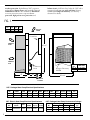
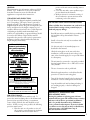
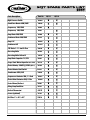
COLD POINT CORPORATION
Cold Point Corporation, Rome, New York 13440
Phone (315)339-2331
Fax (315)339-2358
Web: www.COLDPOINTCORP.com
5QT
SERIES
Replacement Chassis
Installation Operation and Maintenance
Thank You for choosing COLD POINT products!
We have designed and manufactured this unit to be
safe and trouble free. As the installer of this unit, you
play a major role in assuring it's intended
performance and customer satisfaction. The
important information provided here will help you
install the unit correctly and eliminate call-backs. If
you are in need of assistance that is not available or
provided by your local installer/contractor feel free to
write, call, fax or e-mail us at:
Cold Point Corp.
7500 Cold Point Dr.
Rome, NY 13440
Phone:315.339.2331
Fax: 315.339.2358
e-mail: [email protected]
Retain this manual for future reference. A copy
should be left on premises with the maintenance
and/or administrative department at the property.
‘5QT’ PRODUCT DESCRIPTION:
Cold Point '5QT' Series is direct replacement for
Carrier '50QT' series 1½ & 2-ton reverse cycle defrost
heat pump chassis. The chassis is a part of a complete
system, which consists of the chassis, a wall
sleeve/cabinet with louver that is typically built into the
building exterior wall, ductwork, and wall thermostat.
The chassis contains the compressor, indoor and outdoor
heat exchangers, evaporator and condenser motors and
fans, electric heaters, and all controls with exception of
the wall thermostat. The chassis slides into the
sleeve/cabinet for easy removal. The new chassis is
dimensionally identical to the original for a fast, easy,
and trouble free installation. Proven technology, quality
components, careful design and testing, and the latest in
reliability and efficiency advances assure long life, user
satisfaction, and lower energy cost! These full-range heat
pump units with reverse cycle defrost include: bi-flow
thermostatic expansion valve, oversized suction
accumulator, electronic defrost control, compressor
crankcase heater, built-in electric heaters with
02-05
lockout circuit. Cold Point Corp. backs the '5QT' with a
customer friendly one-year parts and labor warranty
and five-year compressor warranty, (see Warranty
document for details).
overheat protection, high efficiency 'PSC' evaporator
and condenser blower motors & dynamically balanced
DWDI blower wheels. Also standard are: Rust-Block*
corrosion protection system, evaporator freeze
protection, high-pressure over protection, and
FIG. 1
Model
A
C
B
No.
5QT- 18 16 ½ 11 ½ 28
5QT- 24 16 ½ 14 7/8 31 3/8
SUPPLY AIR
to ROOM
Control Box
CONDENSER
AIR OUT
43 7/8”
CONDENSER
AIR IN
Condensate
Drain
A
Model
Filter Size
No.
5QT- 18 1” X 16” X 20”
5QT- 24 1” X 20” X 25”
Fiberglass Throwaway
FILTER
B
28 3/16”
C
RETURN AIR
from ROOM
5QT- Packaged Heat Pump Electrical Specifications
Model
No.
Voltage
HZ/PH.
Comp.
RLA
Comp.
LRA
5QT- 18
208/230/60/1
7.4
48.0
1/5
1.3
1/4
1.4
10.1
12
15
197
5QT- 24
208/230/60/1
9.6
60.0
1/5
1.3
1/4
1.4
12.3
15
20
197
Evap. Evap. Mtr. Cond. Cond. Mtr.
AMPS
AMPS
Mtr. HP
Mtr. HP
5QT- Electric Heat Pump Electrical Specifications
Model
No.
5QT- 18
5QT- 24
Voltage
HZ/PH.
KW
208/230/60/1 7.8/9.6
Heater
AMPS
37.5/41.8
Min. CKT
Max
Ampacity Fuse Size
47/53
50A/50A
Total
Amps
Min
Volts
5QT- Packaged Heat Pump Performance Ratings*
5QT- 18
Cooling
BTU/h
EER
20,000
9.9
Heating
BTU/h
COP
20,000
3.4
Recip.
5QT- 24
24,000
24,500
Recip.
Model
No.
*Rated in Accordance with ARI
2
Min. CKT
Max
Ampacity Fuse Size
8.9
3.2
Comp.
Type
portion of the unit contact standing water at
any time.
2. Cover the unit with a water repellant tarp to
protect them from the elements
3. Make provisions for continuous venting of
the covered unit to prevent moisture from
condensing on the unit surfaces.
GENERAL:
These instructions give information relative to COLD
POINT ‘5QT’ model units. Local codes, if different
from these instructions, must be followed and
supplement or supersede these instructions.
UNPACKING AND INSPECTION:
The 5QT chassis is shipped completely assembled and
in it's own package. The exterior louver (optional) is
shipped separately. The wall thermostat (optional) is
shipped inside the chassis. All goods are inspected at the
factory and released to the freight company in good
condition. When received at the site, a visual inspection
of all packages should be made immediately. Any
evidence of rough handling or apparent damage should
be noted on the delivery receipt and the material
inspected in the presence of the carrier's representative.
If damage is found a claim should be filed with the
freight company immediately.
Filter MUST be
cleaned periodically
for parts warranty
to be in effect
CAUTION!!
CONTAINS REFRIGERANT. SYSTEM CONTAINS OIL AND REFRIGERANT
UNDER HIGH PRESSURE. RECOVER REFRIGERANT TO RELIEVE
PRESSURE BEFORE OPENING THE SYSTEM. FAILURE TO FOLLOW
PROPER PROCEDURES CAN RESULT IN PERSONAL ILLNESS OR INJURY
OR SEVERE DAMAGE TO EQUIPMENT.
CAUTION!!
To prevent air by-pass and coil frosting
this panel must be in place at all times.
JOB SITE STORAGE:
These units are intended for in-wall use only. To
protect the unit from damage due to the elements and
prevent it from possibly becoming a contaminant
source of IAQ problems, the unit should be stored
indoors. If indoor storage is not possible, the following
provisions must be met:
1. Place the unit on a dry surface or raise off
the ground to assure adequate air circulation
beneath the unit and to assure that no
PRE-INSTALLATION SAFETY INSTRUCTIONS
Failure to follow these instructions can result in fire or
electrical shock causing serious personal injury or
death and property damage.
!
Read all instructions carefully before proceeding with
the installation. Keep this manual for future
reference.
!
Install or locate the unit only in accordance with
these instructions.
!
Use this unit only for its intended purpose as
described in this manual.
!
Check the rating plate on the new unit before
installation to make certain the unit voltage is the
same as the electrical supply. Do not proceed if there
is a discrepancy.
!
The unit must be connected to a properly grounded
electrical supply. Failure to do so will cause a serious
safety hazard!
!
The use of extension cords is prohibited.
!
Electrical supply must have overload fuse/breaker
protection as stated on unit rating plate.
!
Turn off the electrical supply before beginning the
installation or before service panels are removed!
!
Stop the installation if unit has damaged wiring, is
not working properly, or has been damaged or
dropped.
!IMPORTANT! ALTERATIONS AND
REPLACEMENT PARTS:
Altering the product or replacing parts with non
authorized factory parts will void the factory warranty
and may result in adverse operational performance
and / or a possible hazardous safety condition to
service personnel and occupants. If you are in doubt
as to how to service this unit or where to find factory
replacement parts, call Cold Point Corp. @
315.339.2331 for assistance.
3
Remove Baffle
IMPORTANT INSTALLATION
CONSIDERATIONS:
The installation must comply with all of the
following considerations. Any deficiencies must be
corrected before completing the installation!
Failure to comply will create unsafe and/or
performance and service life problems and will void
the product warranty.
!
All wiring must comply with 'NEC' and local
codes.
!
Carpet, furniture, or other obstructions that will
hinder free airflow to the unit must not block the
return air.
!
!
Shrubs, plants, fences, or structures must not
obstruct outdoor airflow. Building modifications or
structures must not block or obstruct free airflow
to the outdoor section of the unit. Units must not
be positioned such that the discharge air of one
unit blows to the inlet of an adjacent unit.
Outdoor air infiltration around the wall sleeve and
chassis must be sealed. Failure to do so will
overload the room and may result in comfort and
energy cost problems.
REMOVAL OF OLD CHASSIS:
•Locate power supply (breaker box) to unit.
IMPORTANT: Determine how many breakers were
used to power unit. Some units were powered using
individual breakers for the electric heat and compressor
circuits or a single breaker for both circuits.
•Disconnect the power supply by turning off the power
at circuit breaker panel. Be sure to tag or lock the
breaker(s) to prevent accidental or inadvertent reenergizing of circuit.
•Remove front wrapper cover to gain access to chassis.
Remove all necessary hardware to separate chassis from
wall sleeve. Slide chassis out from wall sleeve.
BEFORE INSTALLING NEW CHASSIS:
•Inspect the condition of weather seal gaskets for
shipping damage. Repair or replace if needed.
•Inspect the condition of wall sleeve. Repair if needed.
Check and clean drain in wall sleeve.
4
•IMPORTANT: Remove and save evaporator coil
drain/trap hose, to be used on new chassis.
(see FIG. 1 on pg. 2)
•Verify Louver Type.
!Stamped Louver- Replace with Cold Point Louver.
!Aluminum Louver- Remove Baffle
ALUMINUM LOUVER
STAMPED LOUVER
(REPLACE)
To reinstall unit, reverse the procedure outlined above.
Always check to see that the chassis is sealed to the wall
sleeve to prevent water and air leakage. Replace or add
seals as needed.
CAUTION - Always replace access panels before
turning on main power.
ELECTRICAL WIRING:
NOTE: All electrical wiring must be done by a
qualified electrician and in accordance with NEC and
local codes.
The original Carrier chassis was installed using an
electrical plug type connector, between the chassis
control box and junction box mounted to wall sleeve.
This will be the case for most of the existing
installations. To adapt to the original installation
remove the female electrical connector from the
junction box mounted to wall sleeve. Run a power
supply from the existing junction box to terminal block
on the 5QT chassis.
In some cases you will find a disconnect box mounted
inside of a closet or utility room wall. With this type of
installation you can run the main power from the
disconnect box directly to the terminal block on the new
chassis.
The nameplate on the new chassis indicates the
operating voltage, phase, ampacity, maximum overcurrent protection, and minimum voltage. The power
supply must be in accordance with these requirements!
Use only HACR type circuit breakers. Inadequate
wiring and/or improper electrical supply can cause a
safety hazard and/or fire and will likely result in failure
of the compressor and other electrical components and
voids the warranty. The use of an extension cord is not
allowed.
The 5QT was designed to be wired using a single or
double breaker system, depending on how the existing
unit was wired. On a single breaker system, you will
need to install jumper wires (supplied with each unit) at
the terminal block. With a double breaker system, both
the compressor and electric heat will be wired separately
at terminal block (see FIG. 2). All low volt connections
will be made at defrost board.
FIELD WIRING:
FIG. 2
JUMPERS REQUIRED IF UNIT IS TO
OPERATE HEAT PUMP AND ELECTRIC
HEAT ON A SINGLE CIRCUIT.
Electric Heat
Connections
L1
Compressor
Connections
L1
L2
•The unit will continue to run until thermostat is
satisfied.
DEFROST CYCLE:
•While running in heat pump mode if the defrost
thermostat senses a temperature of 30ºF, the interval
between defrost will begin 30/60/90 min. (factory set at
60min.)
USE (E) TERMINAL ON DEFROST
BOARD FOR (G) CONNECTION
Field Installed
Wires
•If thermostat calls for 2nd stage heat, both heat pump
and electric heat will run.
*RED to RED
BLK to BLK
L2
•At the end of 60 min. run time the condenser fan will
stop and the unit will reverse cycle to cooling and
electric heat will energize.
•The unit will continue to run in this mode until the
defrost thermostat reaches 80ºF or 10min., which ever is
satisfied first.
•Unit will resume normal heating operation.
START-UP, RUN TEST, and OPERATING
INSTRUCTIONS:
CRANKCASE HEATER: The 5QT is equipped with a
crankcase heater. If the temperature is below 65ºF,
operate the crankcase heater 24 hours before starting
unit.
Time spent to assure proper operation will eliminate
call-backs and is time well spent to assure customer
satisfaction.
COLD POINT 5QT series units are designed to operate
from wall mounted thermostats of various designs
including mechanical, mercury bulb, and electronic
types. The following are general guidelines. Refer to the
specific thermostat instructions, and unit wiring diagram
for more detail.
Note that many electronic thermostats have built in
time delay circuitry. These features will affect the onoff timing of the cooling, heat pump, and fan
operation. Some thermostats have programmable
features. Refer to the thermostat instruction sheets
for details of these various functions.
HEATING OPERATION:
(HEAT PUMP with ELECTRIC HEAT)
*Recommend using 2-Stage thermostat.
•Set thermostat system switch to Heat.
Note: Under certain conditions steam may be seen
emanating from the outdoor section during defrost.
This is a normal by product of frost elimination.
COOLING OPERATION:
•Set thermostat system switch to Cooling.
•Set thermostat fan switch to Auto.
•Set the thermostat temperature to a setting lower than
room temperature.
•The compressor, condenser fan and evaporator fan will
run during cooling cycle and produce cool air.
•The unit will continue to run until thermostat is
satisfied.
FINAL INSPECTION:
Do a final visual inspection of the entire installation and
confirm the following:
!The unit is clean and all tools and construction debris
have been picked up.
!Room furnishings, carpets, and the like have been
replaced in their original position.
•Set thermostat fan switch to Auto.
!All controls and protective devices function properly.
•Set the thermostat temperature to a setting warmer
than the room temperature.
•The compressor, condenser fan and evaporator fan will
run during heating cycle and produce warm air.
!The unit air filter is properly installed.
!The unit delivering the proper amount of conditioned
Air.
5
!Unit operation is acceptably quiet and free of
vibration.
!Nothing is obstructing the supply air and return air to
and from the unit.
MAINTENANCE:
Unit performance is maintained at optimum levels by
implementing the following preventive measures:
!FILTER MAINTENANCE
COLD POINT 5QT units are furnished with a
1”X20”X25”throw away type air filter. The unit must
not be operated without this filter installed. Filter
should be inspected at least every three months, and
replaced when dirty. Unit operation becomes very
inefficient with dirty filters and system components are
stressed. Unit warranty is void if filters are not
maintained properly.
Replace only with a filter with an equivalent
pressure drop. Certain “High Efficiency” filters are
not suitable and use of a non-approved type will
Void the 5QT Warranty. If in doubt contact the
factory for technical help in selecting the proper
replacement filter.
!CONDENSATE DRAINS:
Condensate drains can pick up lint and dirt, especially
with dirty filters. Inspect, and if dirty, clean the
condensate drain pan twice a year to avoid the
possibility of overflow.
!CHECK WIRING:
Annually or as a part of a service maintenance check
the tightness of the various wiring connections within
the control panel.
!FAN MOTORS:
The direct-drive blower and fan motors have
permanently sealed, lubricated bearings, and do not
require periodic oiling. Adding a few drops of 20W
non-detergent oil through the oil ports twice a year
may however extend life of the bearings. DO NOT
over oil.
!MICROBIAL GROWTH:
Microbial growth can occur in air conditioners within
the air stream where moisture exists. ASHRAE
standards 62-89 recommends that these surfaces be
inspected and cleaned to limit contamination. This
typically includes surfaces beginning at the finned coil,
drain pan, insulation, and fan/blowers
!INSPECTING AND CLEANING FINNED
EVAPORATOR AND CONDENSER COILS:
Coils become externally fouled as a result of normal
6
operation. Dirt on the surface of the coil reduces its
ability to transfer heat that can result in comfort
problems, increased resistance to airflow and result in
increased operating energy costs. If the dirt on the surface
of the coil becomes wet, such as commonly occurs with
cooling coils, microbial growth can result which may
cause unpleasant odors and serious health related indoor
air quality problems. Coils should be inspected at least
every six months or more often as necessary. The
frequency of the required inspection/cleaning is
dependent on the operating hours of the system, filter
maintenance and efficiency, and dirt build-up. The
following is the suggested method of cleaning coils:
1). Disconnect all electrical power to the unit.
2). Wear the appropriate personal protective equipment.
3). Gain access to the coil section of the unit (both sides).
4). Using a soft brush, remove loose debris from both
sides of the coil.
5). Mix a high quality coil cleaning detergent with water
according to the manufacturers instructions. If the
detergent is strongly alkaline after mixing (8.5 pH or
higher), it must contain a corrosion inhibitor. Carefully
follow the cleaning solution manufacturers instructions
regarding the use of the product.
6). Placed the mixed solution in a pump sprayer or high
pressure sprayer. If a high pressure spryer is used, note the
following:
A. Maintain a minimum nozzle spray angle of 15
degrees.
B. Spray perpendicular to the coil face.
C. Protect other areas of the air handler and
internal controls from contact with moisture or
the cleaning solution.
D. Keep the nozzle at least 6 inches from the coil.
E. Do NOT exceed 600psi.
7). Spray the leaving air side of the coil first, then the
entering air side. Use a block-off to prevent spray from
going through the coil and into a dry section of the unit
and/or system duct-work. Carefully follow the cleaning
solution manufacturers usage instructions.
8). Thoroughly rinse both sides of the coil and the drain
pan with cool, clean water.
9). Repeat steps 7 and 8 as necessary.
10). Using a fin brush straighten any coil fins that may
have been damaged during the cleaning process.
11). Confirm that the drain line remains open following
the cleaning process.
12). Replace all panels and parts.
13). Allow the unit to dry before putting unit back in
service. Restore electrical power to the unit.
14). Be careful that the contaminated material does not
come into contact with other areas of the unit or building.
Properly dispose of all contaminated materials and used
cleaning solution. Store unused solutions according to
manufacturer's directions.
5QT SPARE PARTS LIST
208V
Parts Description
Part No.
High Pressure Switch
5QT-18
5QT-24
50060
X
X
Crank Case Heater 48W, 240V
50025
X
X
Compressor, 208/230V
10002
X
Compressor, 208/230V
10021
Evap Motor 208/230V
15008
X
X
Condenser Motor 208/230V
15013
X
X
Evap Coil
20036
X
X
Condenser Coil
20118
X
X
TXV Valve 1-1 ½ ton Bi-Flow
40030
X
X
Reversing Valve
40109
X
X
Reversing Valve Solenoid
50181
X
X
Evap Motor Capacitor 7.5/370
50027
X
X
Comp./Cond. Motor Capacitor 30/5/370V
50116
X
X
Electric Heater, 4.8 KW @ 230V (QTY. 2)
60103
X
X
Electric Heater Limit Switch
60151
X
X
Transformer 40VA, 24V
50003
X
X
Compressor Contactor 30A, 1 ½ Pole
50047
X
X
Electric Heat Contactor 30A, 2 Pole
50048
X
X
Control Board, Defrost
50081
X
X
Relay, Evap Fan Motor
50131
X
X
Defrost Thermostat
50172
X
X
Louver (optional)
31297
X
X
Air Filter 1” x 20” x 25”
70416
X
X
X
7
All Product Limited Warranty
C o l d Po i n t C o r p o ra t i o n w a r r a n t s t o t h e
purchase/owner, that all products will be free from
defects in material and workmanship under the normal
use and maintenance.
The warranty coverage period:
From the date of original installation: Twelve, (12)
months for all components, and sixty, (60) months
on unit compressors.
Or
From the date of original sale: Fifteen, (15) months
for all components and Sixty-three, (63) months on
unit compressor from the date of original sale.
whichever comes first.
What we will cover:
PARTS: Cold Point Corp. will replace any defective
part with a new or rebuilt part at no charge. The
replacement part then assumes the remaining portion
of the warranty.
LABOR: Repair of defective units for the 12 month/
15 month warranty coverage period. Labor will be
reimbused only in accordance with Cold Point Labor
Allowance Policy Bulletin #PB001A. See Policy
Bulletin for details.
How:
PARTS: Replacement parts, except for compressors,
will be provided at no charge upon receipt of an order.
Failed compressor replacements must be authorized
and returned to Cold Point Corp. Replacement
compressors will be billed when shipped and credited
upon receipt and inspection by Cold Point Corp. See
Return Material Authorization Policy Bulletin
#PB002 for details.
LABOR: Cold Point Corp. service department must
be contacted for authorization of labor coverage prior
to performing service work. Failure to do so will void
the labor warranty.
What we do not cover:
Labor or other costs incurred for removing , installing,
shipping, or handling of defective units.
Normal maintenance
Damage or repairs required as a consequence of faulty
installation or application by others. Failure
to start due to voltage conditions, blown fuses, open
circuit breakers, or other damages due to the
inadequacy or interruption of electrical service.
Damage or repairs needed as a consequence of any
misapplication, abuse, improper servicing,
unauthorized alteration, or improper operation.
Damage as a result of floods, wind, fires, lightning,
accidents, corrosive atmosphere, or other conditions
beyond the control of Cold Point Corp.
Products installed outside the United States or
Canada.
Any damages to person or property of whatever kind,
direct or indirect, special or consequential, whether
resulting from use or loss of the product.
Limit of Warranties: This warranty is exclusive and
in lieu of any implied warranties of merchantability
and fitness for a particular purpose and all other
warranties express or implied. The remedies provided
for in this warranty are exclusive and shall constitute
the only liabilities on the part of Cold Point Corp.
including any statement made by any individual
which shall be of no effect.
For Service, repair, or assistance:
1.) Contact the installer
2.) Call the nearest distributor
3.) Call, write, or e-mail:
Cold Point Corp.
7500 Cold Point Dr.
Rome, NY 13440
Phone: 315.339.2331
Fax: 315.339.2358
Web: www.coldpointcorp.com
REV. A 05-03
8
Before calling please gather and record the following
information so that we are best able to help.
___Unit Model No
___Unit Serial number
___Name of Job or Installation
___Your Name
___Your Company's Name
___Your Company's Address
___Your Company's Phone, Fax, and e-mail
___Room Temperature -DB/WB
___Outdoor Temperature- DB/ WB
___Suction Pressure
___Discharge pressure
___Suction Superheat
___Voltage @ contactor
___Amp Reading (clamp-on)
___Your Diagnosis or Question
Cold Point Corp.
7500 Cold Point Dr.
Rome, NY 13440
Phone:315.339.2331
Fax: 315.339.2358
e-mail: [email protected]
RECORDS:
Date of Installation ______________________
Model number
______________________
Serial number
______________________
Installing Contractor _______________________________________________________
Address _________________________________________________________________
Phone No. _____________________________
SERVICE/MAINTENANCE:
Date
___________
___________
___________
___________
___________
___________
Work Performed
___________________________________________
___________________________________________
___________________________________________
___________________________________________
___________________________________________
___________________________________________
BY
_________________
_________________
_________________
_________________
_________________
_________________
Notes: ________________________________________________________________________
_____________________________________________________________________________
_____________________________________________________________________________
_____________________________________________________________________________
_____________________________________________________________________________
_____________________________________________________________________________
_____________________________________________________________________________
_____________________________________________________________________________
_____________________________________________________________________________
_____________________________________________________________________________
_____________________________________________________________________________
_____________________________________________________________________________
_____________________________________________________________________________
_____________________________________________________________________________
5QT IOM- 02-05
9
Cold Point Corporation
7500 Cold Point Dr.
Rome, New York 13440
Phone 315.339.2331 Fax 315.339.2358 Web: www.COLDPOINTCORP.com