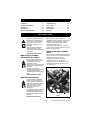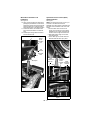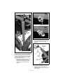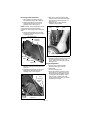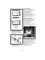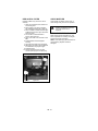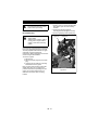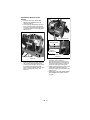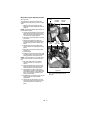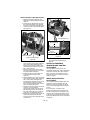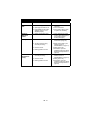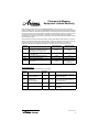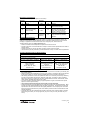
1
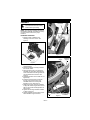
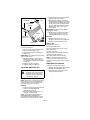
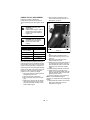
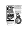
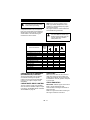
High Wheel Mower
Owner/Operator Manual
Manuel du Propriétaire/Utilisateur
Model
911703 – PRO-24 HWSP
Gasoline containing up to 10% ethanol (E10) or up to 10% MTBE (methyl tertiary butyl
ether) is acceptable for use in this machine.
The use of any gasoline exceeding 10% ethanol (E10) or 10% MTBE will void the product
warranty.
Il est possible d’utiliser de l’essence contenant jusqu’à 10% d’éthanol (E10) ou 10% de
MTBE (éther méthyl-tertiobutylique) sur cette machine.
L’utilisation d’une essence contenant plus de 10% d’éthanol (E10) ou de 10% de MTBE
annulent la garantie.
ENGLISH
FRENCH
04453200 1/12
Printed in USA
TABLE OF CONTENTS
Safety . . . . . . . . . . . . . . . . . . . . . . . . . . . 4
Storage . . . . . . . . . . . . . . . . . . . . . . . . . 33
Assembly . . . . . . . . . . . . . . . . . . . . . . . . 9
Troubleshooting. . . . . . . . . . . . . . . . . . 34
Controls and Features. . . . . . . . . . . . . 14
Service Parts . . . . . . . . . . . . . . . . . . . . 35
Operation . . . . . . . . . . . . . . . . . . . . . . . 15
Accessories . . . . . . . . . . . . . . . . . . . . . 35
Maintenance . . . . . . . . . . . . . . . . . . . . . 19
Specifications . . . . . . . . . . . . . . . . . . . 36
Service and Adjustments . . . . . . . . . . 23
Warranty . . . . . . . . . . . . . . . . . . . . . . . . 37
INTRODUCTION
NON-ENGLISH MANUALS
THE MANUAL
Manuals in languages other than
English may be obtained from
your Dealer. Visit your dealer or
www.ariens.com for a list of
languages available for your
equipment.
Manuals printed in languages
other than English are also
available as a free download on
our website:
http://www.ariens.com
MANUALES EN IDIOMAS
DIFERENTES DEL INGLES
Puede obtener manuales en
idiomas diferentes del inglés en
su distribuidor. Visite a su
distribuidor o vaya a
www.ariens.com para obtener una
lista de idiomas disponibles para
su equipo.
También puede imprimir
manuales en idiomas diferentes
del inglés descargándolos
gratuitamente de nuestra página
Web:
Before using the unit, carefully and
completely read your manuals. The contents
will give you an understanding of safety
instructions and controls during normal
operation and maintenance.
All reference to left, right, front, or rear are
given from the operator’s position, facing the
direction of forward travel.
SERVICE AND REPLACEMENT
PARTS
When ordering replacement parts or making
service inquiries, know the Model and Serial
numbers of your unit and engine.
Numbers are located on the product
registration form in the unit literature
package. They are also printed on a serial
number label, located on the frame of your
unit. See Figure 1.
Engine Serial Number Label
http://www.ariens.com
MANUELS NON ANGLAIS
Des manuels dans différentes
langues sont disponibles chez
votre revendeur. Rendez-vous
chez votre revendeur ou allez sur
le site www.ariens.com pour
consulter la liste des langues
disponibles pour votre
équipement.
Les manuels imprimés dans des
langues différentes de l’anglais
sont également disponibles en
téléchargement gratuit sur notre
site Web :
Unit Serial Number Label
Figure 1
http://www.ariens.com
GB - 2
© Copyright 2012 Ariens Company
DEALER DELIVERY
• Record Unit Model and Serial numbers
here:
• Record Engine Model & Serial numbers
here:
PRODUCT REGISTRATION
The Ariens dealer must register the product
at the time of purchase. Registering the
product will help the company process
warranty claims or contact you with the latest
service information. All claims meeting
requirements during the limited warranty
period will be honored, whether or not the
product registration card is returned. Keep a
proof of purchase if you do not register your
unit.
Customer Note: If the Dealer does not
register your product, please fill out, sign and
return the product registration card to Ariens
or go to www.ariens.com on the internet.
UNAUTHORIZED REPLACEMENT
PARTS
Use only Ariens replacement parts.
Replacing any part on this vehicle with
anything other than an Ariens authorized
replacement part may adversely affect the
performance, durability, or safety of this unit
and may void the warranty. Ariens disclaims
liability for any claims or damages, whether
warranty, property damage, personal injury or
death arising out of the use of unauthorized
replacement parts. To locate your nearest
Ariens Dealer, go to www.ariens.com on the
internet.
CAUTION: DO NOT drop machine when
loading or unloading or damage to rear axle
may occur. Dealer should advise customer of
the same.
Dealer should:
1. Check that all assembly and
adjustments have been properly
completed.
2. Fill out Original Purchaser Registration
Card and return the card to Ariens.
3. Explain Ariens Limited Warranty Policy.
4. Explain recommended lubrication and
maintenance. Advise customer on
adjustments. Remind customer to
change oil in 4 cycle engine crankcase
after first five (5) hours of operation.
5. Instruct customer on controls and
operation of unit. Discuss and
emphasize the Safety Rules. Give
customer Owner/Operator, Parts, and
Engine manuals. Advise customer to
thoroughly read and understand them.
DISCLAIMER
Ariens reserves the right to discontinue,
make changes to, and add improvements
upon its products at any time without public
notice or obligation.The descriptions and
specifications contained in this manual were
in effect at printing. Equipment described
within this manual may be optional. Some
illustrations may not apply to your unit.
GB - 3
SAFETY
CAUTION: POTENTIALLY
HAZARDOUS SITUATION! If not
avoided, MAY RESULT in minor or
moderate injury. It may also be
used to alert against unsafe
practices.
WARNING: This cutting machine
is capable of amputating hands
and feet and throwing objects.
Failure to observe the safety
instructions in the manuals and
on decals could result in serious
injury or death.
Slopes are a major factor related
to slip and fall accidents.
Operation on all slopes requires
extra caution. Maximum slope
angle of operation is 20º.
Tragic accidents can occur if the
operator is not alert to the
presence of children. Never
assume that children will remain
where you last saw them.
Gasoline is extremely flammable
and the vapors are explosive,
handle with care.
Stop unit and engine and allow
moving parts to stop before
leaving operator’s position.
NOTATIONS
NOTE: General reference information for
proper operation and maintenance practices.
IMPORTANT: Specific procedures or
information required to prevent damage to
unit or attachment.
PRACTICES AND LAWS
Practice usual and customary safe working
precautions, for the benefit of yourself and
others. Understand and follow all safety
messages. Be alert to unsafe conditions and
the possibility of minor, moderate, or serious
injury or death. Learn applicable rules and
laws in your area.
REQUIRED OPERATOR
TRAINING
SAFETY ALERTS
Look for these symbols to point
out important safety precautions.
They mean:
Attention!
Original purchaser of this unit was instructed
by the seller on safe and proper operation. If
anyone other than the original purchaser will
use the unit, ALWAYS provide this manual
and any needed safety training before
operation.
Personal Safety Is Involved!
Become Alert!
Obey The Message!
The safety alert symbols above and signal
words below are used on decals and in this
manual.
Read and understand all safety messages.
DANGER: IMMINENTLY
HAZARDOUS SITUATION! If not
avoided, WILL RESULT in death or
serious injury.
WARNING: POTENTIALLY
HAZARDOUS SITUATION! If not
avoided, COULD RESULT in
death or serious injury.
GB - 4
SAFETY DECALS AND
LOCATIONS
2. WARNING!
ALWAYS replace missing or damaged safety
decals. Refer to for safety decal locations.
Do not operate mower unless guards are in
operating position or bagger is attached.
Do not operate mower
unless guards are in
operating position
1
RUN
OFF
07700019A
or bagger is attached.
2
Chock wheels if parking on a
slope.
3
Figure 2
3. DANGER!
1. DANGER!
KEEP HANDS AND FEET AWAY
TO AVOID SERIOUS INJURY OR DEATH
SAFETY RULES
Read the operator’s manual.
Do not allow operation of
machine by untrained personnel.
OL1801
Keep children and others away
from unit while operating.
OL4370
Never direct discharge toward
other people. Thrown objects can
cause injury.
OL0910
Do not operate mower unless
guards are in operating position
or entire bagger is attached.
Keep safety devices (guards,
shields, switches, etc.) in place
and working.
OL3030
If unit is to be used by someone other than
original purchaser; loaned, rented or sold,
ALWAYS provide this manual and any
needed safety training before operation.
Learn applicable rules and laws in your area,
including those that may restrict the age of
the operator.
Read, understand and follow all safety
practices in Owner/Operator Manual before
beginning assembly. Failure to follow
instructions could result in personal injury
and/or damage to unit.
If the operator or the mechanic cannot read
the manual, it is the owner’s responsibility to
explain it to them. Only the user can prevent
and is responsible for accidents or injuries
occurring to themselves, other people or
property.
Do not allow operation of machine by
untrained personnel.
ALWAYS remove key (if equipped) and
disconnect wire from spark plug before
assembly. Unintentional engine start up can
cause death or serious injury.
Complete a walk around inspection of unit
and work area to understand:
• work area
• your unit
• all safety decals.
GB - 5
Clear work area of stones, sticks, wire and
foreign objects which might be picked up and
thrown. Tall grass can hide obstacles.
Know the work area. Stay alert for holes,
rocks, rough terrain and hidden hazards.
Keep away from drop-offs, ditches, or
embankments that could cause operator to
lose footing or control of unit.
ALWAYS be aware of traffic when operating
along streets or curbs.
Keep work area clear of all persons, children
and pets.
Keep children out of the work area and under
the watchful care of a responsible adult.
ALWAYS operate unit when there is good
visibility and light.
DO NOT mow wet grass.
ALWAYS be sure of your footing. Keep a firm
hold on handlebar. Walk, NEVER run.
Engine/blade control feature on mower stops
engine and blade within 3 seconds whenever
operator releases handlebar control. Check
this feature frequently. If feature fails to
operate, disconnect spark plug wire and
adjust or have it repaired before using unit.
Only trained adults may operate or service
unit. Training includes actual operation. The
owner is responsible for training users.
NEVER operate after or during the use of
medication, drugs or alcohol. Unit requires
complete and unimpaired attention.
NEVER allow children to use or service
mower.
ALWAYS keep hands and feet away from
rotating parts. Rotating parts can cut off body
parts.
ALWAYS keep hands away from pinch points.
Fumes from engine exhaust can cause death
or serious injury. DO NOT run engine in an
enclosed area.
ALWAYS protect eyes, face, and body with
adequate safety gear and protective clothes.
Wear sturdy footwear, gloves, a hard hat and
safety goggles or safety glasses with side
shields while operating mower.
Wear appropriate hearing protection.
NEVER operate mower barefoot or when
wearing open sandals or canvas shoes.
NEVER wear loose clothes, long hair or
jewelry that may get caught in rotating parts.
ALWAYS stand clear of discharge when
operating unit.
NEVER direct discharge toward bystanders.
Operator is responsible for bystander safety.
DO NOT touch hot parts. Allow parts to cool.
Keep safety devices or guards in place and
functioning properly. NEVER modify or
remove safety devices.
Read, understand, and follow all instructions
in the manual and on the machine before
starting. Understand:
• How to operate all controls
• The functions of all controls
• How to STOP in an emergency.
DO NOT attempt to start your engine until
you know what the controls do and how they
work.
DO NOT tilt mower when starting it.
Keep feet away when starting engine.
DO NOT start the engine or operate mower
without side discharge cover or side
discharge deflector installed.
Never leave a running unit unattended.
Take all possible precautions when leaving
unit unattended.
ALWAYS shut off engine, remove key
(electric start models) and disconnect spark
plug wire to prevent accidental starting or
unauthorized use.
Stop engine if anyone enters the work area.
NEVER attempt to make any adjustments to
unit while engine is running (except where
specifically recommended). Stop engine,
remove key (electric start models) and wait
for all moving parts to stop before servicing.
DO NOT make cutting height wheel
adjustments while the engine is running.
If you strike an object, or if equipment
vibrates abnormally, stop engine at once, wait
for moving parts to stop and disconnect wire
from spark plug. Repair any damage before
restarting unit.
ALWAYS install side discharge cover when
mulching.
ALWAYS install discharge deflector when
side discharging.
ALWAYS shut off engine, allow blade to stop
and disconnect spark plug wire before
clearing clogs or cleaning unit.
Check for wear, damage, and/or
deterioration. Replace only with Ariens
original equipment replacement parts for
safety.
To reduce fire hazard and overheating, keep
equipment free of grass, leaves, debris or
excessive lubricants.
Use extra care when approaching blind
corners, shrubs, trees, or other objects which
may obscure vision.
GB - 6
DO NOT mow at too fast a rate. DO NOT
change engine governor setting or overspeed the engine.
Do not operate mower on gravel or loose
material such as sand. Stop mower when
crossing drives, walks, or roads to prevent
damage or injury from thrown objects.
DO NOT pull mower backwards unless
absolutely necessary. Look down and back,
especially for small children, before and while
moving backwards.
On self-propelled models, releasing wheel
drive control must stop mower’s forward
movement. If this feature fails to operate,
disconnect spark plug wire and repair before
using unit.
On self-propelled models, wheel drive must
be disengaged when starting engine.
DO NOT operate on steep slopes.
NEVER leave unit unattended on a slope.
Chock wheels if parking on a slope.
Mow across the face of slopes, never up and
down. Be especially cautious when changing
direction on slopes. Maximum slope angle of
operation is 20º.
This product is equipped with an internal
combustion engine. DO NOT use on or near
any unimproved, forest or brush covered land
unless the exhaust system is equipped with a
spark arrestor meeting applicable local, state
or federal laws. A spark arrestor, if used,
must be maintained in effective working order
by the operator. See your Ariens Dealer or
engine manufacturer’s service center.
Accidental engine start up can cause death or
serious injury. Except where specifically
recommended, ALWAYS stop engine,
remove key (electric start models), wait for
moving parts to stop, allow parts to cool and
disconnect spark plug wire before inspecting,
servicing, adjusting or repairing unit.
Avoid Electric Shock. DO NOT disconnect
wire from spark plug while engine is running.
Keep equipment in good condition.
Maintain or replace safety and instruction
labels, as necessary.
Follow engine manufacturer’s safety
instruction when servicing engine.
Check all hardware at regular intervals,
especially blade attachment bolts. Keep all
hardware properly tightened.
An extension spring, when extended, stores
energy and can be dangerous. Always use
tools specifically designed for installing or
removing an extension spring. Always
compress or extend springs slowly.
Before tipping unit, remove fuel and battery (if
equipped).
Use extra care when loading or unloading
unit onto trailer or truck.
CAUTION: DO NOT drop machine when
loading or unloading or damage to rear axle
may occur.
Ensure all wheel blocks, jack stands and tie
downs will support unit during maintenance.
Replace worn-out mufflers immediately.
Continued use could result in fire or
explosion.
Sharp edges can cut or amputate fingers or a
hand. Wrap blade or wear sturdy gloves to
service.
Only replace blades. NEVER straighten or
weld blades.
Use only replacement parts designed for your
unit. See your Ariens Dealer.
Allow engine to cool before storing in any
enclosure.
ALWAYS clean unit before extended storage.
See engine manual for proper storage.
DO NOT store unit inside a building with fuel
in the fuel tank where any ignition sources
are present.
Use only accessories which have been
approved by Ariens and are properly
installed.
Use only accessories or attachments that are
designed for your unit and that can be used
safely on your terrain.
Check attachments frequently and replace
worn or damaged components with
manufacturer’s recommended parts.
GB - 7
Fuel and Fuel System
Emission Control System
Fuel is highly flammable and its vapors are
explosive. Handle with care. Use only an
approved gasoline container with an
appropriately sized dispensing spout.
• NO Smoking!
• NO Sparks!
• NO Flames!
• Allow engine to cool before filling fuel
tank.
Gasoline with up to 10% ethanol (gasohol) or
up to 10% MTBE (methyl tertiary butyl ether)
is acceptable. Use of any gasoline other than
those approved above will void the engine
warranty.
DO NOT OVERFILL. Fill fuel tank to below
bottom of filler neck to allow for fuel
expansion.
This equipment and/or its engine may include
exhaust and evaporative emissions control
system components required to meet U.S.
Environmental Protection Agency (EPA)
and/or California Air Resources Board
(CARB) regulations. Tampering with
emission controls and components by
unauthorized personnel may result in severe
fines or penalties. Emission controls and
components can only be adjusted by an
Ariens Company dealer or an authorized
engine manufacturer's service center.
Contact your Ariens Company Equipment
Retailer concerning emission controls and
component questions.
IMPORTANT: Refer to Engine Manual for
proper fuel type and tank capacity.
Never fill containers inside a vehicle or on a
truck or trailer bed with a plastic liner. Always
place containers on the ground away from
your vehicle before filling.
When practical, remove gas-powered
equipment from the truck or trailer and refuel
it on the ground. If this is not possible, then
refuel such equipment on a trailer with a
portable container, rather than from a
gasoline dispenser nozzle.
Keep the nozzle in contact with the rim of the
fuel tank or container opening at all times until
fueling is complete. Do not use a nozzle lockopen device.
Check fuel supply before starting engine.
DO NOT fill gasoline tank indoors, when
engine is running, or while engine is hot.
Allow engine to cool several minutes before
removing fuel cap.
Replace gasoline tank cap securely and
clean any spilled fuel before starting engine.
If fuel is spilled on clothing, change clothing
immediately.
NEVER store fuel inside where there is an
open flame, such as a water heater.
ALWAYS drain fuel outdoors away from
ignition sources.
ALWAYS shut off engine, and remove key,
and close fuel shutoff valve when transporting
unit on a truck or trailer.
GB - 8
ASSEMBLY
ASSEMBLY
Handlebar
CAUTION: AVOID INJURY. Read
and understand the entire Safety
section before proceeding.
NOTE: The mounting hardware described in
the following assembly procedures is factorymounted on the mower in the proper
locations.
Frame
Handlebar Installation
Handlebar
Support
1. Remove mower, handlebar and
discharge chute from carton. See
Figure 3.
Stud
Figure 4
Support
Clamp
Handlebar
Support
Figure 3
2. Pull both handlebar supports back to
vertical position.
3. Remove handlebar mounting hardware
from mower frame.
4. Place the lower hole of one end of the
handlebar on frame stud. Spread lower
ends of handlebar until the opposite end
can be installed on frame stud. See
Figure 4.
5. Install flanged lock nuts on studs. Do not
tighten fully.
6. Install round head square neck bolts
through upper holes in frame and
handlebar and secure loosely with
flanged lock nuts. See Figure 5.
7. Slide each support clamp on handlebar
to align with vertical support and connect
with hex cap screw and flanged lock nut.
See Figure 5.
8. Tighten all mounting hardware installed
in steps 5 through 7.
9. Tighten hardware securing lower end of
each handlebar support to frame.
Handlebar
Frame
GB - 9
Upper Mounting
Locknut on Stud
Hardware
Figure 5
Wheel Drive Actuation Link
Installation
Operator Presence Control (OPC)
Cable Installation
See Figure 6.
10. Apply pressure against the wheel drive
(self-propel) mechanism to hold it down
against rear wheels. This will provide the
required clearance to install the wheel
drive actuation link on the bellcrank stud.
11. Install a flat washer, the actuation link
and a second flat washer on bellcrank
stud.
12. Install hairpin through bellcrank stud to
secure actuation link.
See Figure 7.
NOTE: The OPC lever (Figure 15, Item 1) is
mounted on the left-hand end of the
handlebar. The OPC cable is routed down the
right side of the handlebar to the front of the
engine.
1. Connect OPC cable end to front of
engine. The Z-bend end of the cable is
installed into the engine flywheel brake
actuation arm through the bottom side.
2. Slide cable wire through slot in cable
mounting bracket.
3. Press cable clip into bracket hole from
backside until tabs lock clip in place.
Bellcrank
Wheel
Drive
Actuation
Link
Flat
Washer
Oil
Fill
Bellcrank
Stud
OPC
Cable End
Hairpin
Cable Clip
Slot
Engine
Flywheel
Brake
Cable
Actuation Mounting
Arm
Bracket
(Front of Engine)
Figure 6
Figure 7
GB - 10
Throttle Cable Installation
7. Position throttle control (on handlebar)
all the way forward (down) to the FAST
position.
8. Push engine throttle lever fully forward
until against its stop. The throttle lever
may also be positioned against its stop
by pulling the throttle cable froward.
9. Tighten the slotted hex cap screw to
secure the clamp on the cable, securing
the cable in place.
10. Install two cable ties to secure the OPC
and throttle cables. See Figure 9.
• The upper tie secures both cables to
the right side of the handlebar just
below the support clamp.
• The lower tie is fed through the hole in
the right side handlebar support to
secure the throttle cable.
• Once secured, clip off excess ends of
cable ties.
See Figure 8.
NOTE: The throttle control (Figure 15, Item 4)
is mounted on the right-hand side of the
handlebar.
1. Remove slotted hex cap screw and
cable clamp from right side of engine.
2. Route throttle cable down between
handlebar and wheel drive actuation
link.
3. Loop end of cable up and back to engine
throttle lever.
4. Install Z-bend end of cable up through
smaller hole in throttle lever.
5. Tilt cable upward until horizontal and
position over clamp mount.
6. Install clamp over cable and attach to
mount with slotted hex cap screw. Do
not tighten cap screw.
Throttle Cable
Cable
End
Clamp Mount
3
Throttle
Cable
Throttle Lever
2
Throttle Lever
Cable Clamp
Cable
Clamp
Cap Screw
Handlebar
Cap Screw
1
Wheel Drive
Actuation Link
Figure 8
GB - 11
Throttle
Cable
Cable Tie
Support Clamp
Handlebar
Rope
Guide
Closed
Recoil Rope
Mounting Cap Screw
Rope
Guide
Opened
Handlebar
Support
Cable
Tie
Figure 10
2. Position recoil rope in upper half of
guide and then rotate lower half back to
close guide, capturing rope. See
Figure 10.
OPC Lever
Handlebar
Bracket
Figure 9
Recoil Rope Set-Up
Loosen lock nut on inner side of handlebar
bracket until rope guide mounting cap screw
is loose enough to allow lower half of guide to
be rotated away from upper half, opening
rope guide. See Figure 10.
1. Hold OPC lever fully depressed while
slowly pulling recoil rope out past
handlebar. Release OPC lever while
holding recoil rope extended. See
Figure 11.
Recoil
Rope
See
Figure 10
Figure 11
NOTE: Ensure mounting cap screw is
properly seated in lower half of rope guide.
3. Tighten lock nut on inner side of
handlebar bracket to secure rope guide
halves together.
GB - 12
Discharge Chute Installation
6. Align front of chute and support plate
with hole in deck and install round head
square neck bolt and flanged lock nut.
See Figure 14.
7. Tighten chute mounting hardware
installed in steps 5 and 6.
1. Place mower in the Service Position.
See SERVICE POSITION on page 20.
2. Remove flanged lock nut and round
head square neck bolt from front of
discharge chute. See Figure 12.
NOTE: DO NOT remove flanged lock nut and
round head square neck bolt securing
together rear of discharge chute and support
plate.
3. Remove three flanged nyloc nuts from
round head square neck bolts at center
of discharge chute.
Install bolt
here.
Support
Plate
Discharge
Chute
Mower
Deck
Discharge Chute
DO NOT
Remove
Hardware
Removed
Figure 14
Wheel Drive Adjustment
Mounting
Bolts
1. Adjust fine adjustment knobs (Figure 26)
as necessary to achieve 1/8" – 1/4"
(3mm – 6mm) drive roller gap at wheels.
See Figure 27.
Support Plate
Figure 12
Engine Preparation
4. Position chute and support plate over
discharge opening in mower deck. See
Figure 13.
5. Install three flanged lock nuts on round
head square neck bolts at center of
discharge chute. Do not tighten.
Discharge Chute
See
Figure 14
Support
Plate
Flanged
Locknuts
Figure 13
GB - 13
1. Check engine oil level and add if
necessary. See engine manual.
2. Fill fuel tank.
3. Connect spark plug wire.
4. Check the Operator Presence Control
(OPC) feature. Try starting the engine
without the OPC lever (Figure 15, Item
1) held against the handlebar. Engine
must not start. If engine starts, stop
engine and bring the unit to your dealer
for adjustment or repair.
CONTROLS AND FEATURES
4
3
5
1
2
8
7
4
6
9
11
10
13
12
Figure 15
1. Operator Presence (Engine/Blade)
Control
2. Recoil Starter Handle
3. Wheel Drive Control Handlebars
4. Engine Throttle Control
5. Air Filter
6. Fuel Tank and Cap
7. Upper (Wheel Drive) Guard
8. Discharge Chute
9. Lower Guard
10. Fixed Front Wheels (Standard)
11. Oil Fill/Dipstick
12. Muffler
GB - 14
OPERATION
Recoil Starter Handle
WARNING: Improper operation
can lead to injury. Learn what the
controls do and how they work.
Thoroughly read and understand
entire Operator Manual.
When pulled, recoil starter handle will turn
engine over.
Engine Throttle
Push throttle forward to
increase engine speed.
Pull throttle backward to
decrease engine speed.
CAUTION: DO NOT operate
mower unless side discharge
deflector is installed. Thrown
objects may cause damage or
injury.
CAUTION: If clog or obstruction
prevents grass flow, release
engine/blade control and
disconnect spark plug wire before
attempting to clear away any
clogs.
Wheel Drive Control
CONTROLS AND FEATURES
The lower, right-side lever must be manually
held against the handlebar to engage wheel
drive. Wheel drive will disengage when this
lever is released. This lever allows for quick
engagement and disengagement of wheel
drive when maneuvering in tight areas or
around obstacles.
See Figure 16 for locations.
Operator Presence Control
CAUTION: Check function of
Engine/Blade Control regularly.
Improper function of control could
cause injury.
NUR
FFO
RUN
OFF
The Operator Presence Control (OPC) lever
must be held against the handlebar to start
the engine and blade.
Releasing the OPC lever grounds engine
spark and applies engine flywheel brake,
stopping the engine and blade within 3
seconds. Check this feature frequently. If
feature fails to operate, disconnect spark plug
wire and adjust or have it repaired before
using unit.
NOTE: Engine must be running for wheel
drive to propel unit.
Wheel drive speed is preset and cannot be
varied during mower operation. The drive
speed may be changed by adjusting the
variable speed (VS) pulley configuration. See
Wheel Drive Speed Adjustment on page 24.
GB - 15
3. Place throttle control in the high-speed
position (all the way forward).
4. With operator presence control lever
held against the handlebar, grasp starter
handle and pull rope slowly until it pulls
harder. This is the compression stroke.
5. Pull rope with rapid continuous full arm
stroke to start engine. Allow rope to
rewind slowly.
IMPORTANT: DO NOT let starter handle
snap against bracket.
6. Repeat step 4 and step 5 until engine
starts. (If engine does not start, see
TROUBLESHOOTING on page 34.)
OPC
Lever
Handlebar
Recoil Starter
Handle
Throttle
Wheel Drive
Control Lever
Shut Off
1. Release wheel drive control, if so
equipped. Allow unit to stop completely.
2. Release operator presence control.
Figure 16
Mowing Tips
FILLING THE FUEL TANK
To add fuel to fuel tank:
1. Put unit in open or well-ventilated area.
2. Stop engine and allow to cool.
3. Clean fuel cap and surrounding area.
4. Remove cap.
IMPORTANT: See engine manual for correct
type and grade of fuel.
5. DO NOT OVERFILL. Fill fuel tank to
below bottom of filler neck to allow for
fuel expansion. See SPECIFICATIONS
on page 36.
6. Replace fuel cap and tighten.
7. ALWAYS clean any spilled fuel.
STARTING AND SHUT OFF
WARNING: Improper operation
can lead to injury. Learn what the
controls do and how they work.
Thoroughly read and understand
entire Operator Manual.
Cut grass when it is dry.
Keep mower blades sharp.
Do not set cutting height too low. For tall
grass, mow twice.
Do not mow too fast.
Mow with engine at full throttle. Discharge
clippings into areas already cut.
Vary cutting pattern with each mowing.
NOTE: To prevent dirt and grass from
collecting on inside of mower deck, avoid
operating over bare ground with only patches
of grass.
EMERGENCY STOPPING
To stop the mower in an emergency:
1. Release the engine/blade (OPC) control.
2. Release the wheel drive control .
3. Allow all moving parts to stop before
leaving operator’s position.
See Figure 15 for all Controls and Features.
NOTE: Start engine on a level surface that is
free of debris. It is recommended that the
engine is started over a non-grassy area, or
over grass that has been cut short.
Starting
1. Check each item in the Before Each Use
section of the MAINTENANCE
SCHEDULE on page 19.
2. Ensure the wheel drive controls, if so
equipped, are disengaged.
NOTE: The engine is equipped with the
ReadyStart® System that features a
temperature-controlled automatic choke. It
does not have a manual choke or a primer.
GB - 16
HEIGHT OF CUT ADJUSTMENT
Height of Cut (HOC) is adjusted by
positioning the front and rear wheels in a
series of mounting holes. See Figures 18 and
19.
5. Hold rear axle bolt stationary with a
wrench while removing outer lock nut.
See Figures 17 and 18.
Axle
Bolt
Outer Nut
Inner Nut
Inside View
DANGER: Avoid injury from
rotating blade.
ALWAYS shut off engine, wait for
moving parts to stop and allow
engine to cool before adjusting
height of cut.
CAUTION: Both rear wheels
must be set at same height or
traction drive will not work
properly.
Cutting Height Settings Chart
Wheel Axle Hole
(Front & Rear)
Wheel
Height of Cut
4 (Top)
2" (51mm)
3
2.7" (69mm)
2
3.3" (84mm)
1 (Bottom)
4" (102mm)
Rear Wheel Height Adjustment
Rear wheel height is changed by raising or
lowering axles in the four available mounting
holes in frame. Place axles in upper holes for
a lower cut and lower holes for a higher cut.
Height-of-cut holes are spaced approximately
0.665" (17mm) apart. The mower is set-up at
the factory in the second from the lowest
position, for a 2.7" (69mm) cut height.
1. Stop engine, wait for all moving parts to
stop and hot parts to cool.
2. Place unit on a flat, level surface.
3. Disconnect spark plug wire from spark
plug.
4. Raise back of mower to lift rear wheels
off the ground. Support rear of mower
deck with jackstands, blocking or other
similar, stable support.
Frame
Figure 17
6. Remove wheel/tire assembly from axle
bolt.
7. Hold rear axle bolt stationary with a
wrench while removing inner nut. See
Figure 18.
8. Move each rear wheel axle bolt to
desired height-of-cut hole.
9. Install inner nut on axle bolt so flange of
nut is against mower frame. Hold rear
axle bolt stationary with a wrench while
tightening inner nut securely against
frame.
10. Install wheel/tire assembly on axle bolt.
11. Install outer lock nut on axle bolt so
flange of nut is against wheel. Hold rear
axle bolt stationary with a wrench while
tightening outer lock nut.
12. Connect spark plug wire to spark plug.
NOTE: Traction adjustment may be
necessary to correspond to rear wheel height
settings.
13. Adjust wheel drive traction as necessary.
Refer to the Wheel Drive Traction
Adjustment on page 25.
GB - 17
Frame
Height
of Cut
Holes
Wheel
Axle
Bolt
Inside View
The height of the standard, fixed front wheels
is changed by raising or lowering wheels in
the four available mounting holes in each
wheel support. Place wheels in upper holes
for a lower cut and lower holes for higher cut.
NOTE: Height-of-cut holes are spaced
approximately 0.665" (17mm) apart. The
mower is set-up at the factory in the second
from the lowest position, for a 2.7" (69mm)
cut height.
5. Hold axle bolt stationary with wrench
while removing inner nut.
6. Move each front wheel and axle bolt to
desired height-of-cut hole.
7. Hold axle bolt stationary with wrench
while tightening inner nut against
support.
8. Connect spark plug wire to spark plug.
Wheel
Inner
Nut
Axle
Bolt
Outer
Nut
Figure 18
Front Wheel Height Adjustment
See Figure 19
IMPORTANT: Front wheel height must be set
the same as rear wheel height for proper
height of cut.
1. Stop engine, wait for all moving parts to
stop and hot parts to cool.
2. Place unit on a flat, level surface.
3. Disconnect spark plug wire from spark
plug.
4. Raise front of mower to lift front wheels
off the ground. Support front of mower
deck with jackstands, blocking or other
similar, stable support.
GB - 18
Support
Figure 19
Height
of Cut
Holes
MAINTENANCE
MAINTENANCE SCHEDULE
CAUTION: AVOID INJURY. Read
and understand the entire Safety
section before proceeding.
NOTE: Some working conditions (heavy
loads, high ambient temperatures, dusty
conditions, or airborne debris) may require
more frequent service.
See engine manual for further maintenance
and troubleshooting information.
Ariens Dealers will provide any service, parts
or adjustments which may be required to
keep your unit operating at peak efficiency.
Should engine require service, contact an
Ariens Dealer or an authorized engine
manufacturer's service center.
WARNING: HOT SURFACES
can cause death or serious injury.
DO NOT TOUCH parts which are
hot from operation. ALWAYS
allow parts to cool.
MAINTENANCE SCHEDULE
Service Performed
Before 25 Hours 50 Hours
Each
Use
Check Engine/Blade Control
Check Wheel Drive Control
Clean Unit
Check Engine Oil
Check Mower Blade
Check Fasteners
Check Wheel Drive Belts (2)
Check Blade Drive Belt
General Lubrication
Clean Air Filter
Change Engine Oil & Filter
Check Muffler
Replace Spark Plug
After first 5 Hours of operation
100 Hours
or
Annually
•
•
•
•
•
•
•
•
•
•
*• •
•
•
*
CHECK OPERATOR PRESENCE
(ENGINE/BLADE) CONTROL
CLEAN UNIT
Before each use clean unit, use a brush to
clean recoil guard, all control linkage and
muffler guard of debris. See engine manual
for instructions. Clean oil, grease or fuel spills
to prevent fires.
The engine and blade must stop within 3
seconds after releasing the operator
presence control. If the engine and blade
continue to run, adjust or repair control
immediately.
CHECK WHEEL DRIVE CONTROL
The unit must stop quickly and completely
when the control is released. Adjust or repair
if necessary. See WHEEL DRIVE CONTROL
ADJUSTMENT on page 32.
CHECK ENGINE OIL
IMPORTANT: Maintain proper oil level at all
times or engine damage will result.
Check the level of the engine crankcase oil
before each use.
Make sure engine is level when checking oil.
See engine manual for instructions.
GB - 19
SERVICE POSITION
Install Mower Blade
Put unit into service position for easy access
to underneath the deck.
NOTE: Ensure blade air lift points upward.
See Figure 20.
1. Replace blade, flat washer and lock nut
on shaft.
2. Torque lock nut to 187 – 253 lb-ft (254 –
343 N•m).
3. Connect spark plug wire to spark plug.
CAUTION: Avoid fuel spills. Follow
steps below to help prevent fuel
spills. If fuel leaks into air cleaner,
replace air cleaner. ALWAYS clean
up any spilled fuel.
Sharpening Mower Blades
1. Stop engine, wait for all moving parts to
stop and hot parts to cool.
2. Place unit on a flat, level surface.
3. Disconnect spark plug wire from spark
plug.
4. Remove fuel cap, place a piece of
plastic bag over the opening and tighten
cap securely.
5. Tip unit onto left side, opposite the
discharge opening.
Make sure unit is secure and will not tip
over.
CAUTION: DO NOT sharpen
mower blades while on unit. An
imbalanced mower blade will
cause excessive vibration and
eventual damage to unit. Check
mower blade balance before
reinstalling blades.
NEVER weld or straighten bent
blades.
CAUTION: Mower blades are
sharp and can cut you. Wrap the
blades or wear gloves, and use
extra caution when servicing
them.
IMPORTANT: After service is complete and
unit is upright, remove plastic from fuel cap
and connect spark plug wire to spark plug.
CHECK MOWER BLADE
Check blade mounting: blade must be secure
and bolt torqued to 187 – 253 lb-ft (254 –
343 N•m). Bolt should fully compress lock
washer.
Check blade for nicks and dull cutting edges.
Sharpen if necessary.
Check blade for rounded or broken ends,
thinned metal or other damage. Replace if
necessary.
CAUTION: Mower blades are
sharp and can cut you. Wrap the
blades or wear gloves, and use
extra caution when servicing
them.
1. Remove mower blade from unit. See
Remove Mower Blade on page 20.
Discard mower blade if:
• More than 1/2 in. (1.27 cm) of metal is
removed. See Figure 20.
• Air lifts become eroded.
• Blade is bent or broken.
2. Sharpen mower blade by removing an
equal amount of material from each end
of mower blade. Blade should be
sharpened back at an angle from the
center to the outside tip. DO NOT
change vertical angle of cutting edge or
round corner of mower blade. See
Figure 20.
Remove Mower Blade
1. Place mower in the Service Position.
See SERVICE POSITION on page 20.
2. Block blade to prevent rotation.
3. Remove lock nut, flat washer and blade
from shaft.
GB - 20
CHECK FASTENERS
DO NOT sharpen to this pattern.
2
1
Check all fasteners for proper tightness. Pay
special attention to blade hardware and all
guards, shields and safety devices.
CHECK DRIVE BELTS
3
OT0792
Sharpen to this pattern.
Check tension of mower blade and wheel
drive belts. See BELT TENSION
ADJUSTMENT on page 27. Check drive belts
for wear and/or damage and replace as
necessary. See BELT REPLACEMENT on
page 30.
GENERAL LUBRICATION
DISCARD If More Than 1/2 in. (1.27 cm)
2
Lubricate wheel drive shaft through grease
fitting every to 16 hours of operation. Lightly
oil all other moving parts every 25 hours of
operation. Wipe off excess oil to avoid
accumulation of dirt and debris.
CLEAN AIR FILTER
Clean air filter every 50 hours of operation.
See engine manual for specific information.
See Figure 22 for air filter location.
4
3
1.
2.
3.
4.
Square Corner
Cutting Edge
Air Lift
Air Lift Erosion
Muffler
Air Filter Cover Knob
Figure 20
3. Check mower blade balance. Slide
mower blade on an unthreaded bolt. A
balanced blade should remain in a
horizontal position. If either end of
mower blade moves downward, sharpen
the heavy end until blade is balanced.
See Figure 21.
Blade
Figure 22
CHANGE ENGINE OIL
Bolt
OA0013
Change engine crankcase oil after first five
(5) hours of operation. Then change oil after
every 50 hours of operation or annually.
Figure 21
4. Install mower blade on unit. See Install
Mower Blade on page 20.
5. Tighten mounting bolt to a torque of 187
– 253 lb-ft (254 – 343 N•m).
IMPORTANT: Proper oil level must be
maintained at all times or engine damage will
result. DO NOT overfill. Be sure engine is
level when adding oil.
NOTE: Refer to Engine Manual for
instructions and proper oil type.
GB - 21
REPLACE OIL FILTER
CHECK MUFFLER
Replace oil filter every 50 hours of use or
annually.
1. Clean dirt and debris from oil filter and
surrounding area.
2. Place mower in the Service Position.
See SERVICE POSITION on page 20.
3. Place a suitable container below engine
oil fill tube and remove cap to allow oil to
drain from tube.
4. Turn oil filter counterclockwise to
remove. See Figure 23.
5. Apply a thin coat of oil onto seal of new
filter.
6. Install new filter and hand tighten
securely.
7. Tip mower back down onto its wheels.
8. Add engine oil. Refer to Engine Manual
for instructions and proper oil type.
9. Install oil fill cap.
10. Remove plastic from fuel cap and
connect spark plug wire to spark plug.
Check muffler for debris, cracks, wear, or
other damage every 50 hours of operation.
CAUTION: Replace worn-out
mufflers immediately. Continued
use could result in fire or
explosion.
REPLACE SPARK PLUG
Spark plug should be replaced every 100
hours of operation or annually. See engine
manual for specific information.
NOTE: Loose spark plug wire terminals can
cause sparking. Replace terminal if
damaged.
Oil Fill Tube with Cap/Dipstick
Oil Filter
Figure 23
GB - 22
SERVICE AND ADJUSTMENTS
To install a guard:
1. Position guard on mower and slide bolts
with captive nyloc nuts into mounting
brackets.
2. Thread each mounting bolt into
mounting bracket and tighten securely.
3. Connect spark plug wire to spark plug.
CAUTION: AVOID INJURY. Read
and understand the entire Safety
section before proceeding.
WHEEL DRIVE ADJUSTMENTS
Drive Belt Guard
See
Figure 27
DANGER: Avoid injury from
rotating blade.
ALWAYS shut off engine, wait for
moving parts to stop and allow
engine to cool before removing
guards.
All mowers are equipped with the lower guard
that covers the blade spindle and drive belt.
The self-propelled model includes an upper
guard that covers the wheel drive
components. Both guards attach in the same
manner using similar hardware.
To remove a guard:
1. Shut off unit.
2. Disconnect spark plug wire from spark
plug.
3. Unscrew two hex bolts from mounting
brackets and remove guard.
Each mounting bolt includes a captive flat
washer and nyloc nut. The captive nut
prevents the bolt from separating from the
guard. The mounting bolt secures to a
weldnut on the back of each mounting
bracket.
GB - 23
See
Figure 26
See Figure 25
Figure 24
See Figure 27
Wheel Drive Speed Adjustment
The wheel drive lower belt connects the
mower blade shaft to a variable speed (VS)
pulley. Wheel drive speed is determined by
how deep the wheel drive lower belt rides in
the VS pulley. The higher the belt rides in the
VS pulley groove, the slower the wheel drive
speed. The lower the belt rides in the VS
pulley groove, the faster the wheel drive
speed. See Figures 24 and 25.
1. Remove both the upper and lower
guards. See WHEEL DRIVE
ADJUSTMENTS Drive Belt Guard on
page 23.
2. Loosen the wheel drive lower belt
tension. See Adjust Wheel Drive Lower
Belt Tension on page 27.
3. Loosen set screw in VS pulley.
4. To change wheel drive speed:
• Rotate the pulley outer half clockwise,
moving it inward. This causes the belt
to ride higher in pulley, decreasing
wheel drive speed.
• Rotate the pulley outer half
counterclockwise, moving it outward.
This causes the belt to ride lower in
pulley, increasing wheel drive speed.
5. Tighten the VS pulley set screw onto
one of the flats of the shaft to secure it in
position.
6. Tighten the wheel drive lower belt
tension. See Adjust Wheel Drive Lower
Belt Tension on page 27.
7. Install both the upper and lower guards.
See WHEEL DRIVE ADJUSTMENTS
Drive Belt Guard on page 23.
Belt Higher In Groove
Set
Screw
VS
Pulley
Half
Slower Walking Speed
Belt Lower In Groove
Set
Screw
VS
Pulley
Half
Faster Walking Speed
Wheel Drive Upper Belt
Set
Screw
Flat on
Shaft
Wheel Drive Lower Belt
Figure 25
GB - 24
VS Pulley
Outer Half
Wheel Drive Traction Adjustment
The gap (clearance) between the drive rollers
and tires, when wheel drive is disengaged, is
used to set the amount of contact force
(traction) when wheel drive is engaged. Drive
roller to wheel gap should be 1/8" – 1/4"
(3mm – 6mm).
NOTE: A smaller gap between rollers and
tires when wheel drive is disengaged
provides for more engaged traction, which is
helpful on sloped terrain.
On each side of the mower, the lower end of
the wheel drive frame pivots from an
adjustment plate (See Figure 28). The upper
right side of the frame is connected by a link
to the end of the engage plate. The opposite
end of the engage plate pivots from the bell
crank post. See Figure 26.
NOTE: A series of holes in the engage plate
allow traction adjustments to correspond to
rear wheel height (cutting height) settings.
1. Remove both the upper and lower
guards. See WHEEL DRIVE
ADJUSTMENTS Drive Belt Guard on
page 23.
2. Turn fine adjustment knob
counterclockwise to bring it to the top
end of adjustment link. Do not remove
knob.
3. Remove hairpin and washer from bell
crank post.
4. Remove engage plate from bell crank
post where engage plate is mounted.
5. Push the wheel drive frame back until
drive roller gap at wheels is 1/8" – 1/4"
(3mm – 6mm). See Figure 27.
6. Install nearest hole of engage plate onto
bell crank post. See Figure 26.
7. Install hairpin and washer on bell crank
post.
8. Turn fine adjustment knob clockwise to
adjust drive roller gap at wheels to be
1/8" – 1/4" (3mm – 6mm). See
Figure 27.
9. Install both the upper and lower guards.
See WHEEL DRIVE ADJUSTMENTS
Drive Belt Guard on page 23.
GB - 25
Fine Adjustment Knob
See
Figure
27
Adjustment Link
Wheel
Drive
Frame
Engage Plate
Washer
Figure 26
GB - 26
Hairpin
Bell Crank
5. While holding adjustment bolt stationary
with a wrench, tighten flanged nut
against adjustment bracket.
6. Tighten flanged lock nut and bolt
attaching each adjustment plate to the
adjustment bracket.
7. Install both the upper and lower guards.
See WHEEL DRIVE ADJUSTMENTS
Drive Belt Guard on page 23.
Drive
Roller
Adjustment Plate
Tire
Figure 27
Adjustment Bracket
1/8 - 1/4"
(3mm – 6mm)
Gap
Hex
Bolt
BELT TENSION ADJUSTMENT
Adjust Wheel Drive Lower Belt
Tension
Flanged
Nut
The wheel drive lower belt connects the
mower blade shaft to a variable speed (VS)
pulley on the wheel drive frame.
On each side of the mower, the wheel drive
frame pivots from adjustment plates
connected to adjustment brackets. A hex bolt
mounted through each bracket contacts the
plate to set the frame position. See Figure 28.
1. Remove both the upper and lower
guards. See WHEEL DRIVE
ADJUSTMENTS Drive Belt Guard on
page 23.
NOTE: The adjustment bracket bolt holes are
threaded.
2. Loosen lock nut and bolt attaching each
adjustment plate to the adjustment
bracket. Do not remove hardware.
IMPORTANT: To avoid bending adjustment
bolts, or have them slip off adjustment
brackets, it may be necessary to pull back on
wheel drive assembly as lower belt tension is
adjusted.
NOTE: The adjustment bracket bolt holes are
threaded.
3. Loosen flanged nut on each adjustment
hex bolt away from adjustment bracket.
4. Turn both adjustment bolts in/out evenly
to get 1-1/4" – 1-1/2" (3.175 – 3.810cm)
flex in belt. Use the pressure of one
finger at the center of the belt span to
check for proper flex.
NOTE: Adjust bolt lengths as necessary to
tension belt while maintaining even drive
roller to wheel gap at both wheels.
GB - 27
Lock Nut
Adjustment
Bracket
Blade Drive Belt
Figure 28
Wheel
Drive
Lower Belt
Adjust Wheel Drive Upper Belt
Tension
Wheel Drive
Frame
The wheel drive upper belt connects the
variable speed (VS) pulley to the drive rollers
shaft.
1. Remove both the upper and lower
guards. See WHEEL DRIVE
ADJUSTMENTS Drive Belt Guard on
page 23.
NOTE: The bearing holders slide vertically on
the wheel drive frame.
2. Loosen two flanged lock nuts and round
head square neck bolts securing each
bearing holder to wheel drive frame. Do
not remove mounting hardware. See
Figure 29.
NOTE: Use the pressure of one finger at the
center of the belt span to check for proper
flex.
3. Pull drive rollers shaft up to tension
upper belt to flex 1/4", ±1/8" (6mm,
±3mm).
4. Snug two flanged lock nuts and round
head square neck bolts securing each
bearing holder to wheel drive frame.
5. Check that drive rollers shaft is level
horizontally by measuring the position of
both bearing holders on the wheel drive
frame. The positions should be equal
(±1/8") on both sides.
6. If adjustment is necessary, gently tap on
bearing holders to make position
adjustments.
7. Tighten the two flanged lock nuts and
round head square neck bolts securing
each bearing holder to wheel drive
frame.
8. Install both the upper and lower guards.
See WHEEL DRIVE ADJUSTMENTS
Drive Belt Guard on page 23.
Bolt and
Flanged
Lock Nut
Wheel
Drive
Drive Rollers
Upper Belt
Shaft
GB - 28
Blade Drive Belt
Figure 29
Bearing
Holder
Adjust Mower Blade Drive Belt
Tension
1. Remove lower guard. See WHEEL
DRIVE ADJUSTMENTS Drive Belt
Guard on page 23.
2. Loosen the four flanged lock nuts from
the round head square neck bolts that
secure the engine mounting plate to the
mower frame. Do not remove hardware.
See Figure 30.
Mounting Bolts
Flanged Nyloc Nut
Belt
Tensioning Bolt
Engine
Mounting Plate
Mower Frame
Engine Mounting Plate
Figure 31
Frame
Figure 30
3. Hold the flanged nyloc nut (on the inside
of the engine mounting plate) stationary
with a wrench while turning the belt
tensioning bolt clockwise. As the end of
the bolt extends against the mower
frame, the engine mount plate is forced
back, increasing belt tension. See
Figure 31.
GB - 29
4. Tension belt to get a maximum of 80 lbs
of tension. This correlates to
approximately 0.250" (6.35mm) flex in
belt. Use the pressure of one finger at
the center of the belt span to check for
proper flex. See Figures 28 and 29.
5. Tighten the four flanged lock nuts on the
round head square neck bolts that
secure the engine mounting plate to the
mower frame.
6. Install lower guard. See WHEEL DRIVE
ADJUSTMENTS Drive Belt Guard on
page 23.
BELT REPLACEMENT
Adjustment Plate
Adjustment Bracket
Wheel Drive Lower Belt Replacement
See Figure 32.
The wheel drive lower belt connects the blade
shaft top pulley to a variable speed (VS)
pulley.
1. Remove both the upper and lower
guards. See WHEEL DRIVE
ADJUSTMENTS Drive Belt Guard on
page 23.
NOTE: The adjustment bracket bolt holes are
threaded.
2. Loosen the lock nut and bolt attaching
each adjustment plate to the adjustment
bracket. Do not remove hardware.
IMPORTANT: To avoid bending adjustment
bolts, or have them slip off adjustment
brackets, it may be necessary to pull back on
wheel drive assembly as lower belt tension is
adjusted.
NOTE: The adjustment bracket bolt holes are
threaded.
3. Loosen the flanged nut on each
adjustment hex bolt away from the
adjustment bracket.
4. Turn both adjustment bolts out evenly
until belt becomes loose enough to slide
off blade shaft pulley.
NOTE: If the wheel drive lower belt is
installed backwards it will drive the variable
speed (VS) pulley in reverse. The drive rollers
shaft will then also be driven in reverse. If
driven in reverse, the drive roller detents will
be heard to click and wheel drive action will
not occur.
5. When installing belt, twist belt 90º so left
side strand goes to lower side of VS
pulley. Also see Figure 29.
6. Turn both adjustment bolts in/out evenly
to get 1-1/4" – 1-1/2" (3.175 – 3.810cm)
flex in belt. Use the pressure of one
finger at the center of the belt span to
check for proper flex.
NOTE: Adjust bolt lengths as necessary to
tension belt while maintaining even drive
roller to wheel gap at both wheels.
7. While holding adjustment bolt stationary
with a wrench, tighten flanged nut
against adjustment bracket.
GB - 30
Hex
Bolt
Flanged
Nut
Lock Nut
Adjustment
Bracket
Wheel
Drive
Lower Belt
Blade Drive Belt
Figure 32
8. Tighten flanged lock nut and bolt
attaching each adjustment plate to the
adjustment bracket.
9. Install both the upper and lower guards.
See WHEEL DRIVE ADJUSTMENTS
Drive Belt Guard on page 23.
Wheel Drive Upper Belt Replacement
See Figure 33.
The wheel drive upper belt connects the
variable speed (VS) pulley to the drive rollers
shaft.
1. Remove wheel drive lower belt. See
Wheel Drive Lower Belt Replacement on
page 30.
NOTE: The bearing holders slide vertically on
the wheel drive frame.
2. Loosen two flanged lock nuts and round
head square neck bolts securing each
bearing holder to wheel drive frame. Do
not remove mounting hardware.
3. Push drive rollers shaft down to release
belt tension.
4. Remove two flanged lock nuts and
round head square neck bolts securing
left-side bearing holder to wheel drive
frame.
5. Remove belt from drive rollers shaft
pulley and then the variable speed (VS)
pulley.
6. Bring belt over left-side bearing holder
and remove.
7. Install new belt.
8. Install two round head square neck bolts
and flanged lock nuts to secure left-side
bearing holder to wheel drive frame.
NOTE: Use the pressure of one finger at the
center of the belt span to check for proper
flex.
9. Pull drive rollers shaft up to tension
upper belt to flex 1/4", ±1/8" (6mm,
±3mm).
10. Snug two flanged lock nuts and round
head square neck bolts securing each
bearing holder to wheel drive frame.
11. Check that drive rollers shaft is level
horizontally by measuring the position of
both bearing holders on the wheel drive
frame. The positions should be equal
(±1/8") on both sides.
12. If adjustment is necessary, gently tap on
bearing holders to make position
adjustments.
13. Tighten the two flanged lock nuts and
round head square neck bolts securing
each bearing holder to wheel drive
frame.
Wheel Drive
Frame
Bolt and
Flanged
Lock Nut
Bearing
Holder
Wheel
Drive
Drive Rollers
Upper Belt
Shaft
Blade Drive Belt
Figure 33
14. Install wheel drive lower belt. See Wheel
Drive Lower Belt Replacement on
page 30.
GB - 31
Mower Blade Drive Belt Replacement
1. Remove wheel drive lower belt. See
Wheel Drive Lower Belt Replacement on
page 30.
2. Loosen the four flanged lock nuts from
the round head square neck bolts that
secure the engine mounting plate to the
mower frame. Do not remove hardware.
See Figure 34.
Mounting Bolts
Flanged Nyloc Nut
Belt
Tensioning Bolt
Engine
Mounting Plate
Blade Drive Belt
Mower Frame
Frame
Figure 35
Engine Mounting Plate
9. Install wheel drive lower belt. See Wheel
Drive Lower Belt Replacement on
page 30.
Figure 34
3. Hold the flanged nyloc nut (on the inside
of the engine mounting plate) stationary
with a wrench while turning the belt
tensioning bolt counterclockwise. This
will back the bolt away from the mower
frame. See Figure 35.
4. Force the motor mount plate forward
until belt is slack enough to remove from
the mower blade shaft pulley.
5. Install new belt on engine pulley and
mower spindle lower pulley. See
Figure 33.
6. Hold the flanged nyloc nut (on the inside
of the engine mounting plate) stationary
with a wrench while turning the belt
tensioning bolt clockwise. As the end of
the bolt extends against the mower
frame, the engine mount plate is forced
back, increasing belt tension.
7. Tension belt to get a maximum of 80 lbs
of tension. This correlates to
approximately 0.250" (6.35mm) flex in
belt. Use the pressure of one finger at
the center of the belt span to check for
proper flex. See Figures 32 and 33.
8. Tighten the four flanged lock nuts on the
round head square neck bolts that
secure the engine mounting plate to the
mower frame.
OPERATOR PRESENCE
(ENGINE/BLADE) CONTROL
ADJUSTMENT
The engine/blade control has no user
serviceable adjustments. If the engine/blade
control does not stop the engine or blade
within 3 seconds of releasing the control
lever, take the unit to an authorized Ariens
dealer for repairs.
WHEEL DRIVE CONTROL
ADJUSTMENT
The unit should stop immediately when the
wheel drive control is released. The unit
should not creep forward when the wheel
drive control is disengaged with the engine
running.
If the unit creeps, increase the gap
(clearance) between the drive rollers and
tires when wheel drive is disengaged. If the
unit does not accelerate smoothly or seems
to slip under load, increase the traction and
speed. See Wheel Drive Traction Adjustment
on page 25.
GB - 32
STORAGE
Engine
CAUTION: AVOID INJURY. Read
and understand the entire Safety
section before proceeding.
When storing unit for extended periods of
time, remove all fuel from tank and carburetor
(run dry). Refer to Engine Manual.
IMPORTANT: NEVER spray unit with highpressure water or store unit outdoors. Store
mower in a cool, dry, protected location.
Cleaning
Allow unit to cool. Clean unit thoroughly with
mild soap and low pressure water. Brush off
dirt and debris from all surfaces. Touch up all
scratched surfaces to prevent rust. Matching
touch-up paint is available from your Ariens
Dealer. Do not use abrasives, solvents, or
harsh cleaners.
Inspection
Inspect mower and repair or replace worn or
damaged parts to avoid delays when
beginning use again.
Regularly check all hardware and keep
fasteners tight. Know unit is in safe working
condition.
Fuel System
Gasoline left in the fuel system for extended
periods without a stabilizer will deteriorate,
resulting in deposits in the system. These
deposits can damage the carburetor and the
fuel hoses, filter and tank. Prevent deposits
from forming in the fuel system during
storage by adding a quality fuel stabilizer to
the fuel. Follow the recommended mix ratio
found on the fuel stabilizer container.
To treat the fuel system for storage:
1. Add fuel stabilizer according to
manufacturer’s instructions.
2. Run engine for at least 10 minutes after
adding stabilizer to allow it to reach the
carburetor.
NEVER store the engine with fuel in the fuel
tank inside of a building with potential
sources of ignition.
GB - 33
TROUBLESHOOTING
PROBLEM
PROBABLE CAUSE
CORRECTION
Engine will not
start
1. Fuel tank empty or low.
Engine is
difficult to
restart
1. Mower clogged with grass.
1. Clear clippings from under
mower. (Allow the mower to
clear clippings before
shutting off engine.)
Cut is poor
1. Worn blade.
1. Check blade (see SERVICE
POSITION on page 20).
2. Too much grass is being
removed per cutting.
2. Raise cutting height. (see
HEIGHT OF CUT
ADJUSTMENT on page 17)
3. Allow grass to dry.
4. Mow slower. (For selfpropelled model, see Wheel
Drive Speed Adjustment on
page 24)
2. Spark plug wire loose or off.
3. Engine/Blade control cable
detached, broken, or not
adjusted properly.
3. Grass is too wet.
4. Mowing speed is too fast.
Grass does
not disperse
evenly
1. Too much grass is being
removed per cutting.
2. Grass is too wet.
3. Mowing speed is too fast.
GB - 34
1. Check fuel level. Fill tank if
necessary.
2. Check connection.
3. Check cable. Adjust, repair
or replace as necessary.
1. Raise cutting height. (see
HEIGHT OF CUT
ADJUSTMENT on page 17)
2. Allow grass to dry.
3. Mow slower. (For selfpropelled model, see Wheel
Drive Speed Adjustment on
page 24)
PROBLEM
Wheel drive
does not
engage
PROBABLE CAUSE
CORRECTION
1. Wheel drive control not
engaged.
2. Wheel drive belts tension too
loose.
1. Engage wheel drive control.
2. Check wheel drive belts
tension. Adjust as necessary
(see BELT TENSION
ADJUSTMENT on page 27).
3. Replace belt. (see BELT
REPLACEMENT on
page 30)
4. Check wheel drive control
linkage. Adjust or replace as
needed. See CHECK
WHEEL DRIVE CONTROL
The unit must stop quickly
and completely when the
control is released. Adjust or
repair if necessary. See
WHEEL DRIVE CONTROL
ADJUSTMENT on page 32.
on page 19.
5. Contact your Dealer.
6. See Wheel Drive Speed
Adjustment on page 24.
See Wheel Drive Traction
Adjustment on page 25.
7. Install wheel drive lower belt
in correct orientation. See
Wheel Drive Lower Belt
Replacement on page 30.
3. Wheel drive belt worn or
damaged.
4. Wheel drive control linkage
detached or broken.
5. Bearings damaged.
6. Drive seems to slip or speed is
too slow. Inadequate traction
on sloped terrain.
7. Wheel drive rollers run in
reverse.
SERVICE PARTS
ACCESSORIES
Always use genuine Ariens parts to keep
your mower running like new.
See your authorized Ariens Dealer to add
these optional accessories.
Description
Part Number
71106800
Mulching Kit, 24"
Air Filter
21535600
71106900
Front Swivel Wheel Kit
Pre-Cleaner,
Air Filter
04278300
71107000
High-Traction Rear Tire Kit
Spark Plug
04278500
Oil Filter
04278400
Blade
04159600
Wheel Drive
Upper Belt
07200538
Wheel Drive
Lower Belt
07206000
Mower Blade
Drive Belt
07200537
GB - 35
SPECIFICATIONS
Model Number
911703
Description
PRO 24HWSP
Length – in. (cm)
60 (152.4)
Height – in. (cm)
39 (99)
Width – in. (cm)
24 (61)
Actual Weight – lbs (kg)
152
Cutting Width – in. (cm)
24 (61)
Cutting Height – in. (cm)
2–4
(5.1 – 10.2)
Briggs & Stratton
Professional Series
EPA/CARB Compliant
Engine, 4 cycle
Ready Start
8.50 Gross Torque
Engine Model
Max Rotation Speed of Cutting
Edge – feet per minute
15,400
Governed RPM (May be
different from maximum rpm.)
3,200 ± 100
Displacement Cu. In. (cc)
12 (190)
Cylinder Bore
Cast Iron Sleeve
Engine Oil Type
See engine manual.
Crank Case Capacity – Oz.
(Liter)
20 (0.59)
Oil System
Full Pressure
Engine Oil Filter
Spin-On
Spark Plug Gap – in. (mm)
See engine manual.
Fuel Type
Unleaded
Fuel Tank Capacity – qt (Liter)
1 (0.95)
Primer Bulb
N/A
Choke
N/A
Throttle
Air Cleaner
Cable-Actuated
Paper Element with Foam Pre-cleaner
Starting
Recoil
Variable Speeds – MPH
(km/hr)
Mower Deck
0 – 4.7 mph
11 Gauge - Stamped Steel
Front Wheel Dia – in. (cm)
8 (20.3)
Rear Wheel Dia – in. (cm)
20 (50.8)
Rear Tire Pressure – psi (kPa)
35 (241)
GB - 36
Commercial Mowing
Equipment Limited Warranty
Ariens Company (Ariens) warrants to the original purchaser that Ariens, Gravely and Countax brand
products purchased on or after 1/1/2012 and designated or labeled commercial products by Ariens Company
will be free from defects in material and workmanship for the time period noted in the chart below. Equipment
put to personal use around a single household or residence is considered "Consumer Use"; equipment put to
any business use (agricultural, commercial, or industrial) or used at multiple locations is considered
"Commercial Use." If any product is rented or leased, then the duration of these warranties shall be 90 days
after the date of purchase.
An authorized Ariens dealer (Ariens brand products), Gravely dealer (Gravely brand products), or Countax
dealer (Countax brand products) will repair any defect in material or workmanship, and repair or replace any
defective part, subject to the conditions, limitations and exclusions set forth herein. Such repair or
replacement will be free of charge (labor and parts) to the original purchaser except as noted below.
Warranty
Code
Product Group
Warranty Period
Consumer Use
Warranty Period
Commercial Use
3 Years
2 Years
2 Years
CA
Pro-Turn 100 & 200, Pro-Master,
Compact-Pro, Pro-Stance, Pro-Ride,
Pro-Walk Mowers, Pro-Zoom, etc.
CB
Turf Mowing Equipment: CL, TRM, TVM,
FP, PM-3084, etc.
3 Years
CC
Pro 20 Series Walk-Behind Mowers
3 Years
1 Year
N/A
Service (replacement) Parts
90 Days (no labor)
90 Days (no labor)
CD
Pro-Turn 400
3 Years
3 Years (Years 1 & 2:
Parts & Labor, Year 3:
Parts Only)
Special Extensions
The chart below details special extensions to this warranty:
Warranty
Code
Warranty Exception
Warranty
Period
Use
Detail
CA
Mower Deck Shell on
Commercial Mowers
Lifetime
All
2 Years parts and labor (Commercial),
3 Years parts and labor (Consumer),
parts-only thereafter.
CA
Main Frame on
Commercial Mowers
Lifetime
All
2 Years parts and labor (Commercial),
3 Years parts and labor (Consumer),
parts-only thereafter.
CA
Cast Iron Deck Spindles
3 Years
All
3 Years for all users including
Commercial.
CB
Reels
Lifetime
All
Warranty on reels only against bending
or breaking.
Commercial_2012
37
Exceptions and Limitations
The chart below details special exceptions to this warranty:
Warranty
Code
Warranty Exception
Warranty
Period
Use
Detail
All
Batteries
1 Year
All
Prorated
All
Belts, Muffler, Tires
None
Commercial
All
Cloth, Plastic, and Rubber
Components (Including
Belts and Cables)
Maximum
2 Year
All
Warranty is limited to 2 years for
consumer use. Except as noted
above, these components are
covered for defect, not for wear.
All
Engines
See Engine
Manufacturer’s
Warranty
All
Engines are covered by engine
manufacturer’s warranty. Refer to
engine manufacturer’s warranty
statement.
These components are not covered
when used commercially.
Customer Responsibilities
Register the product immediately at the time of sale. If the dealer does not register the product, the
customer must complete the product registration card in the literature package and return it to the Ariens
Company, or register the unit online at www.ariens.com, www.gravely.com, www.countax.com.
To obtain warranty service, the original purchaser must:
• Perform the maintenance and adjustments explained in the owner's manual.
• Promptly notify Ariens or an authorized Ariens, Gravely or Countax service representative of the need for
warranty service.
• Transport the product to and from the place of warranty service at owner's expense.
• Have the warranty service performed by an authorized Ariens, Gravely or Countax service representative.
To Find an Authorized Service Representative:
In the U.S. and Canada:
Use the dealer locator on our websites:
www.ariens.com
•
www.gravely.com
Or contact us by mail or by phone:
In the U.S., Canada, Mexico, Caribbean, In Europe, Asia, Africa or
Central and South America:
the Middle East:
Ariens Company
655 W. Ryan Street
Brillion, WI 54110
Phone: (920) 756 - 4688
www.ariens.com
Countax Ltd, Countax House
Great Haseley, Oxfordshire,
OX44 7PF
Phone: 0800 597 7777
www.countax.com
In Australia or New Zealand:
109-111 Abbot House
Hallam, Victoria 3803 Australia
Phone: (03) 9796 4244
1800 335 489
www.bynorm.com.au
Exclusions - Items Not Covered by This Warranty
• Parts that are not genuine Ariens, Gravely or Countax service parts are not covered by this warranty and
may void the warranty.
• Damages resulting from the installation or use of any part, accessory, or attachment which is not approved
by the Ariens Company for use with product(s) identified herein are not covered by this warranty.
• The following maintenance, service and replacement items are not covered by this warranty unless they
are noted in the Limitations section above: lubricants, spark plugs, oil, oil filters, air filters, fuel filters,
brake linings, brake arms, brake shoes, skid shoes, scraper blades, shear bolts, mower blades, mower
vanes, brushes, headlights, light bulbs, knives, cutters.
• Any misuse, alteration, improper assembly, improper adjustment, neglect, or accident which requires
repair is not covered by this warranty.
• Use of gasoline blends exceeding 10% ethanol voids any and all warranties.
• Products are designed to the specifications in the area that the product was originally distributed. Different areas may have significantly different legal and design requirements. This warranty is limited to the
requirements in the area in which the unit was originally distributed. Ariens Company does not warrant
this product to the requirements of any other area. Warranty service is limited to service within the area
originally distributed.
• In countries other than the United States and Canada, contact the Ariens Company dealer for warranty
policies that govern within your country. Rights may vary from country to country and within any one
country.
Commercial_2012
38
Disclaimer
Ariens Company may from time to time change the design of its products. Nothing contained in this warranty
shall be construed as obligating the Ariens Company to incorporate such design changes into previously
manufactured products, nor shall such changes be construed as an admission that previous designs were
defective.
LIMITATION OF REMEDY AND DAMAGES
Ariens Company's liability under this warranty, and under any implied warranty that may exist, is limited to
repair of any defect in workmanship, and repair or replacement of any defective part. Ariens Company shall
not be liable for incidental, special, or consequential damages (including lost profits). Some states do not
allow the exclusion of incidental or consequential damages, so the above limitation or exclusion may not
apply to you.
AUSTRALIAN CONSUMER LAW
The following applies solely to warranties subject to Subsection 102(1) of the Australian Consumer Law: Our
goods come with guarantees that cannot be excluded by the Australian Consumer Law. You are entitled to a
replacement or refund for a major failure and for compensation for any other reasonably foreseeable loss or
damage. You are also entitled to have the goods repaired or replaced if the goods fail to be of acceptable
quality and failure does not amount to a major failure.
DISCLAIMER OF FURTHER WARRANTY
Ariens Company makes no warranty, express or implied, other than what is expressly made in this
warranty. If the law of your state provides that an implied warranty of merchantability, or an implied
warranty of fitness for particular purpose, or any other implied warranty, applies to Ariens Company,
then any such implied warranty is limited to the duration of this warranty. Some states do not allow
limitations on how long an implied warranty lasts, so the above limitation may not apply to you.
This warranty gives you specific legal rights, and you may also have other rights which vary from region to region.
Commercial_2012
39
CALIFORNIA AND EPA (UNITED STATES ENVIRONMENTAL
PROTECTION AGENCY) EVAPORATIVE EMISSION CONTROL
WARRANTY STATEMENT
YOUR WARRANTY RIGHTS AND OBLIGATIONS
The CARB (California Air Resources Board), the EPA, and Ariens Company are pleased to explain the
evaporative emission control system's warranty on your 2012 model year small off-road equipment. In
California, new equipment that uses small off-road engines must be designed, built, and equipped to
meet the State's stringent anti-smog standards. Ariens Company must warrant the evaporative
emission control system on your small off-road equipment for the period listed below provided there
has been no abuse, neglect or improper maintenance of your equipment.
Your evaporative emission control system may include parts such as: fuel tanks, fuel lines, fuel caps,
valves, canisters, filters, vapor hoses, clamps, connectors, and other associated components.
MANUFACTURER'S WARRANTY COVERAGE:
This evaporative emission control system is warranted for two years. If any evaporative
emission-related part on your equipment is defective, the part will be repaired or replaced by Ariens
Company.
OWNER'S WARRANTY RESPONSIBILITIES:
• As the small off-road equipment owner, you are responsible for the performance of the required
maintenance listed in your Owner's Manual. Ariens Company recommends that you retain all
receipts covering maintenance on your small off-road equipment, but Ariens Company cannot deny
warranty solely for the lack of receipts.
• As the small off-road equipment owner, you should however be aware that the Ariens Company may
deny you warranty coverage if your evaporative emission control system part has failed due to
abuse, neglect, or improper maintenance or unapproved modifications.
• You are responsible for presenting your small off-road equipment to an authorized Ariens, Gravely,
or Parker service representative as soon as the problem exists. The warranty repairs should be
completed in a reasonable amount of time, not to exceed 30 days. If you have a question regarding
your warranty coverage, you should contact Ariens Company Technical Service Center at
1-920-756-2141.
DEFECTS WARRANTY REQUIREMENTS:
(a.) The warranty period begins on the date the small off-road equipment is delivered to an ultimate
purchaser.
(b.) General Evaporative Emissions Warranty Coverage. Ariens Company warrants to the ultimate
purchaser and any subsequent owner that the evaporative emission control system when
installed was:
(1.) Designed, built, and equipped so as to conform with all applicable EPA and CARB
regulations; and
(2.) Free from defects in materials and workmanship that causes the failure of a warranted part
for a period of two years.
(c.) The warranty on evaporative emissions-related parts will be interpreted as follows:
(1.) Any warranted part that is not scheduled for replacement as required maintenance in the
written instructions must be warranted for the warranty period defined in subsection (b)(2).
If any such part fails during the period of warranty coverage, it must be repaired or replaced
by the Ariens Company. Any such part repaired or replaced under the warranty must be
warranted for a time not less than the remaining warranty period.
(2.) Any warranted part that is scheduled only for regular inspection in the written instructions
must be warranted for the warranty period defined in subsection (b)(2). A statement in such
written instructions to the effect of "repair or replace as necessary" will not reduce the
period of warranty coverage. Any such part repaired or replaced under warranty must be
warranted for a time not less than the remaining warranty period.
(3.) Any warranted part that is scheduled for replacement as required maintenance in the
written instructions must be warranted for the period of time prior to the first scheduled
replacement point for that part. If the part fails prior to the first scheduled replacement, the
part must be repaired or replaced by the Ariens Company. Any such part repaired or
replaced under warranty must be warranted for a time not less than the remainder of the
period prior to the first scheduled replacement point for the part.
CARB/EPA 2012
40
(4.)
(5.)
(6.)
(7.)
(8.)
(9.)
Repair or replacement of any warranted part under the warranty provisions of this article
must be performed at no charge to the owner at an authorized Ariens, Gravely, or Parker
service representative.
Notwithstanding the provisions of subsection (4) above, warranty services or repairs must
be provided at authorized Ariens, Gravely, or Parker service representatives that are
franchised to service the subject small off-road equipment.
The owner must not be charged for diagnostic labor that leads to the determination that a
warranted part is in fact defective, provided that such diagnostic work is performed at an
authorized Ariens, Gravely, or Parker service representative.
Throughout the evaporative emission control system's warranty period set out in subsection
(b)(2), the Ariens Company must maintain a supply of warranted parts sufficient to meet the
expected demand for such parts.
Manufacturer-approved replacement parts must be used in the performance of any
warranty maintenance or repairs and must be provided without charge to the owner. Such
use will not reduce the warranty obligations of the manufacturer issuing the warranty.
The use of any add-on or modified parts will be grounds for disallowing a warranty claim
made in accordance with this article. The manufacturer issuing the warranty will not be
liable under this Article to warrant failures of warranted parts caused by the use of an
add-on or modified part.
Evaporative Emission Warranty Parts List
The following parts are considered emission-related components for evaporative emissions:
• Fuel Tank, Fuel Cap and Tether
• Fuel Line, Fuel Line Fittings, Clamps*
• Pressure Relief Valves, Control Valves*
• Control Solenoids*, Electronic Controls*
• Vacuum Control Diaphragms*
• Control Cables*, Control Linkages*
• Purge Valves
• Vapor Hoses, Liquid/Vapor Separator
• Carbon Canister, Canister Mounting Brackets
• Carburetor Purge Port Connector
* As related to the evaporative emission control system
Disclaimer
New equipment sold in the state of California that uses small off-road engines must be exclusively
certified and appropriately labeled for sale in California. Some equipment covered by this Owner's
Manual my not be certified for sale in California and the presence of the preceding CARB and EPA
Warranty Statement does not by its existence indicate which, if any, of the equipment covered by this
Owner's Manual may be sold in California.
Some equipment covered by this Owner's Manual may have been manufactured prior to certain
affectivity dates requiring the inclusion of evaporative emission control systems. Therefore some
equipment covered by this Owner's Manual may not include the evaporative emission control systems
referred to in the preceding CARB and EPA Warranty Statement.
CARB/EPA 2012
41
Ariens
655 West Ryan Street
Brillion, WI 54110
920-756-2141
Fax 920-756-4688
www.ariens.com