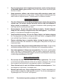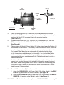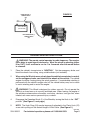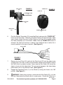
1
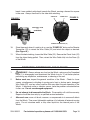
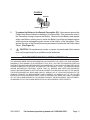
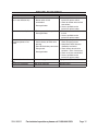
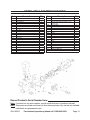
PORTABLE REMOTE CONTROL
WINCH 12 VOLT - 3,000 LB. CAPACITY
Model 95912
Assembly And Operation Instructions
Due to continuing improvements, actual product may differ slightly from the product described herein.
®
3491 Mission Oaks Blvd., Camarillo, CA 93011
Visit our website at: http://www.harborfreight.com
To prevent serious injury, read and understand
all warnings and instructions before use.
Copyright© 2007 by Harbor Freight Tools®. All rights reserved. No portion of this
manual or any artwork contained herein may be reproduced in any shape or form
without the express written consent of Harbor Freight Tools.
For technical questions or replacement parts, please call 1-800-444-3353.
Specifications
Electrical Requirements
12 VDC Power Input
1.1 HP / Permanent Magnet
6’Length Battery Wires (Qty. 2)
Maximum Line Pull Capacity
3,000 Pounds
Remote Control
Hand Held Wireless (A = “Power In” / B = “Power Out”)
Gear Ratio
153.1
Cable Assembly
32 Ft. x 3/16” Diameter / High Carbon Steel, Zinc Plated
Hook Assembly
Spring Loaded Safety Latch
1” Jaw Opening
3-1/2” Long x 2-1/2” Wide x 1/2” Thick
Mounting Plate Dimensions
7.086” Long x 4.881” Wide x 2.165” High
Overall Dimensions
12.204” Long x 7.086” Wide x 6.299” High
Weight
18.9 Pounds
Save This Manual
You will need this manual for the safety warnings and precautions, assembly,
operating, inspection, maintenance and cleaning procedures, parts list and assembly
diagram. Keep your invoice with this manual. Write the invoice number on the inside of the
front cover. Write the product’s serial number in the back of the manual near the assembly
diagram, or write month and year of purchase if product has no number. Keep this manual
and invoice in a safe and dry place for future reference.
Unpacking
When unpacking, check to make sure that the item is intact and undamaged. If any
parts are missing or broken, please call Harbor Freight Tools at the number shown on the
cover of this manual as soon as possible.
GENERAL SAFETY RULES
WARNING!
READ AND UNDERSTAND ALL INSTRUCTIONS
Failure to follow all instructions listed below may result in
electric shock, fire, and/or serious injury.
SAVE THESE INSTRUCTIONS
Work Area
1.
Keep your work area clean and well lit. Cluttered benches and dark areas invite
accidents.
REV 07h, 09c
SKU 95912
For technical questions, please call 1-800-444-3353.
Page 2
2.
Do not operate power tools in explosive atmospheres, such as in the presence
of flammable liquids, gases, or dust. Power tools create sparks which may ignite
the dust or fumes.
3.
Keep bystanders, children, and visitors away while operating a power tool.
Distractions can cause you to lose control. Protect others in the work area from
debris such as chips and sparks. Provide barriers or shields as needed.
Personal Safety
1.
Stay alert. Watch what you are doing, and use common sense when operating
a power tool. Do not use a power tool while tired or under the influence of
drugs, alcohol, or medication. A moment of inattention while operating power
tools may result in serious personal injury.
2.
Dress properly. Do not wear loose clothing or jewelry. Contain long hair.
Keep your hair, clothing, and gloves away from moving parts. Loose clothes,
jewelry, or long hair can be caught in moving parts.
3.
Avoid accidental starting. Be sure the Power Switch is off before plugging
in. Carrying power tools with your finger on the Power Switch, or plugging in power
tools with the Power Switch on, invites accidents.
4.
Remove adjusting keys or wrenches before turning the power tool on. A
wrench or a key that is left attached to a rotating part of the power tool may result
in personal injury.
5.
Do not overreach. Keep proper footing and balance at all times. Proper footing
and balance enables better control of the power tool in unexpected situations.
6.
Use safety equipment. Always wear eye protection. Dust mask, nonskid safety
shoes, hard hat, or hearing protection must be used for appropriate conditions.
Always wear ANSI-approved safety goggles and a dust mask/respirator when using
or performing maintenance on this tool.
Tool Use And Care
1.
Do not force the tool. Use the correct tool for your application. The correct
tool will do the job better and safer at the rate for which it is designed. Do not force
the tool and do not use the tool for a purpose for which it is not intended.
2.
Store idle tools out of reach of children and other untrained persons. Tools
are dangerous in the hands of untrained users.
3.
Maintain tools with care. Keep cutting tools clean. Properly maintained tools
are less likely to malfunction and are easier to control. Do not use a damaged tool.
Tag damaged tools “Do not use” until repaired.
SKU 95912
For technical questions, please call 1-800-444-3353.
Page 3
4.
Check for misalignment or binding of moving parts, breakage of parts, and any
other condition that may affect the tool’s operation. If damaged, have the tool
serviced before using. Many accidents are caused by poorly maintained tools.
5.
Use only accessories that are recommended by the manufacturer for your
model. Accessories that may be suitable for one tool may become hazardous
when used on another tool.
Service
1.
Tool service must be performed only by qualified repair personnel. Service or
maintenance performed by unqualified personnel could result in a risk of injury.
2.
When servicing a tool, use only identical replacement parts. Follow instructions
in the “Inspection, Maintenance, And Cleaning” section of this manual. Use of
unauthorized parts or failure to follow maintenance instructions may create a risk
of electric shock or injury.
SPECIFIC SAFETY RULES
1.
Do not exceed the maximum line pull capacity (3,000 pounds) of this Winch.
Know the weight of the load being pulled. Overloading the Winch could cause
personal injury and/or property damage.
2.
Maintain labels and nameplates on the Winch. These carry important information.
If unreadable or missing, contact Harbor Freight Tools for a replacement.
3.
Prior to using the Winch, make sure to read and understand all warnings, safety
precautions, and instructions as outlined in the manufacturer’s instruction
manual for the vehicle/trailer to which the Winch will be attached.
4.
Make sure to read and understand all instructions and safety precautions as
outlined in the manufacturer’s instruction manual for the vehicle/trailer you
will winch.
5.
Industrial applications must follow OSHA guidelines.
6.
Never leave the Winch unattended with a load. Remove the load from the Winch
before leaving.
7.
Do not allow children and other unauthorized people to handle or play with the
Winch.
8.
This Winch is designed for intermittent use only. Do not use the Winch in a
constant duty application. The duration of the pulling job should be kept as short
as possible. If the Winch becomes very hot to the touch, stop the Winch and let it
cool down for several minutes. Never pull for more than one minute at or near the
rated maximum line pull capacity (3,000 pounds).
SKU 95912
For technical questions, please call 1-800-444-3353.
Page 4
9.
Always examine the Winch for structural cracks, bends, damage, frayed Cable,
and any other condition that may affect the safe operation of the tool. Do not
use the Winch even if minor damage appears.
10.
Always keep hands and fingers away from the Gears, Drum, Cable, and all other
moving parts when applying or releasing a load. Remain clear of the Cable when
pulling a load. Do not stand in line with the Cable, as it can whip violently should
it break. Do not cross over or under the Cable when the Winch is under a load.
People and animals should be kept at a safe distance when using the Winch.
11.
Use extreme caution when applying or releasing a load. Never allow the load
to suddenly release. Slowly and carefully apply and release the load.
12.
Never winch a vehicle, trailer, boat, or other object with anyone in or on the
object being pulled. Use a “spotter” to assist you in assuring that it is safe to
operate the Winch. Make sure the spotter is out of the way of the Cable and object
being pulled before activating the Winch.
13.
This Winch is designed for mounting on square or rectangular surfaces only.
Do not attempt to mount the Winch on a rounded surface.
14.
This Winch is not designed to accommodate ropes or fiberglass straps. Do not replace the original Cable with a Cable of lesser strength. Refer to the “Product
Specifications” section in this manual for the proper replacement Cable.
15.
Always leave at least five turns of the Cable on the Drum to prevent pulling
the Cable completely out of the Winch.
16.
The Cable must be pulled straight in. Keep the load in line with the Winch. Pulling
at an angle (off to the side) may cause excessive stress on the Winch.
17.
This Winch is not designed for use in aircraft applications.
18.
Never lift objects vertically with the Winch. This Winch is designed for horizontal
use only.
19.
Make sure the input voltage to the Winch is 12 volt DC. Do not attempt to use
any other electrical power source.
20.
Do not move the vehicle to assist the Winch in pulling a load. The combination
of the Winch and vehicle pulling together can overload the Winch and the Cable.
21.
When using the Winch to move a load, place the vehicle transmission in neutral,
set the emergency brake, and chock all the wheels of the vehicle. The vehicle
engine should be running during the winch operation. If considerable winching is
performed with the vehicle engine shut off, the vehicle battery may be too weak to
assist winching and to restart the engine.
SKU 95912
For technical questions, please call 1-800-444-3353.
Page 5
22.
WARNING! This Winch is designed for outdoor use only. Do not operate
the Winch in a closed area or in a poorly ventilated area. When running, the engine
of the vehicle product produces carbon monoxide, a colorless, odorless, toxic gas
that, when inhaled, can cause serious personal injury or death.
23.
WARNING! People with pacemakers should consult their physician(s) before
use. Electromagnetic fields in close proximity to a heart pacemaker could cause
pacemaker interference or pacemaker failure.
24.
WARNING! The warnings and precautions discussed in this manual cannot
cover all possible conditions and situations that may occur. It must be understood
by the operator that common sense and caution are factors which cannot be built
into this product, but must be supplied by the operator.
SAVE THESE INSTRUCTIONS
ASSEMBLY INSTRUCTIONS
1.
NOTE: Depending on your level of knowledge regarding mechanical assembly and electrical wiring, you may wish to have the assembly and mounting performed
by a qualified service technician.
2.
Select a mounting site on the vehicle’s front bumper or other suitable location.
CAUTION! This Winch can generate 3,000 pounds of pulling force. Make sure the location selected can withstand this much force. It may be necessary to use steel reinforcement plates (not included) and/or to weld on additional bracing (not included), depending on the desired mounting location.
SKU 95912
For technical questions, please call 1-800-444-3353.
Page 6
5/16”
MOUNTING
HOLE
NUT (25)
LOCK
WASHER
(25)
5/16”
MOUNTING
HOLE
BOLT (25)
WASHER
(25)
FIGURE A
5/16”
MOUNTING
HOLE
5/16”
MOUNTING
HOLE
3.
Place the Mounting Base (3) of the Winch on the desired mounting location. Using the four 5/16” diameter mounting holes in the Mounting Base as a template,
mark and drill four 5/16” mounting holes in the mounting location.
(See Figure A.)
4.
Use the four Mounting Bolts (25), Washers (25), Lock Washers (25), and Nuts (25) to securely attach the Winch to the desired mounting location.
(See Figure A.)
5.
Plan a route for the Winch’s Power Cables (26) to the point of where the Cables will
be connected to the vehicle’s 12 volt battery. The route should be secure, out of the
way of moving parts, hot parts, road debris, or any or maintenance of the vehicle.
For example, the Cables may be routed under the vehicle, attaching them to the frame using suitable fasteners (not included). Do not attach the Cables to the exhaust system, drive shaft, emergency brake, fuel line, or any other components which may create damage to the Cables through heat or motion, or create a fire hazard.
If a hole is drilled through the bumper or any other part of the vehicle, make sure to install a rubber grommet (not included) in the hole to prevent fraying of the Cables. When drilling, make sure no wires or cables are in the drilling path.
The Winch’s Power Cables (26) should not be drawn taut. Make sure to leave slack for some Cable movement.
6.
Once the Power Cables (26) have been routed.
f. Attach the RED/POSITIVE (+) Power Cable (26) of the Winch to the RED/
POSITIVE (+) terminal on the vehicle’s battery. (See Figure B.)
g. Attach the BLACK/NEGATIVE (--) Power Cable (26) of the Winch to the BLACK/
NEGATIVE (--) terminal on the vehicle’s battery. (See Figure B.)
SKU 95912
For technical questions, please call 1-800-444-3353.
Page 7
RED/POSITIVE (+)
POWER CABLE
(26)
FIGURE B
VEHICLE BATTERY
(NOT INCLUDED)
BLACK/NEGATIVE (--)
POWER CABLE
(26)
OPERATING INSTRUCTIONS
WARNING! The remote control operates by radio frequency. The receiver
has a delay to avoid signal interference. When the winch is operating (either
IN or OUT), it will continue to run for 1 to 2 seconds after the remote button
is released.
1.
Place the vehicle’s transmission in “NEUTRAL”. Set the emergency brake, and
block the wheels from rolling, using suitable chocks (not included).
2.
When using the Winch to move a load, place the vehicle transmission in neutral,
set the emergency brake, and chock all the wheels of the vehicle. The vehicle
engine should be running during the winch operation. If considerable winching is
performed with the vehicle’s engine shut off, the vehicle battery may be too weak
to assist winching and to restart the engine.
3.
WARNING! This Winch is designed for outdoor use only. Do not operate the
Winch in a closed area or in a poorly ventilated area. When running, the engine of
the vehicle produces carbon monoxide, a colorless, odorless, toxic gas that, when
inhaled, can cause serious personal injury or death.
4.
Disengage the Freewheel Knob (1) of the Winch by turning the Knob to the “OUT”
position. (See Figure C, next page.)
5.
NOTE: The Hook Strap (24) may be temporarily attached to the Clevis Hook (22)
as an aid in pulling out the desired length of Wire Cable. (See Figure C.)
SKU 95912
For technical questions, please call 1-800-444-3353.
REV 08d
Page 8
WIRE CABLE
(22)
FIGURE C
“POWER OUT”
FIGURE D
“POWER IN”
FREEWHEEL KNOB
(1)
(DISENGAGED)
CLEVIS HOOK
(22)
HOOK STRAP
(24)
6.
REMOTE TRANSMITTER
(23)
Point the Remote Transmitter (23) toward the Winch, and press the “POWER OUT”
button on the Transmitter. Then pull out the Wire Cable to the desired length. Make
sure to leave at least five turns of Wire Cable on the Drum (5) to prevent pulling
the Cable completely out of the Winch. Note: Once the POWER OUT button is
released, the winch will continue to release a few additional feet of cable; this is
normal operation for this type of product. (See Figure D.)
CLEVIS HOOK
(22)
FIGURE E
7.
Remove the Hook Strap (24), and hook the Clevis Hook (22) onto the object using
a pulling point, tow strap, or chain (none included). Make sure the Safety Latch on
the Clevis Hook is properly in place. Never wrap the Wire Cable (22) around the
object or hook onto the object itself. This can cause damage to the object being
pulled and/or kink or fray the Wire Cable. (See Figure E.)
8.
Engage the Freewheel Knob (1) on the Winch by turning the Knob to the “IN”
position. (See Figure F.)
9.
WARNING! Never allow anyone to stand near the Wire Cable (22), or in line
with the Cable behind the Winch while it is under power. Should the Cable slip or
REV 07c, 08k
SKU 95912
For technical questions, please call 1-800-444-3353.
Page 9
break it can suddenly whip back towards the Winch, causing a hazard for anyone
in the area. Always stand well to the side while winching.
“POWER IN”
FIGURE F
“POWER OUT”
FIGURE G
FREEWHEEL KNOB
(1)
(ENGAGED)
REMOTE TRANSMITTER (23)
10.
Stand clear and, when it is safe to do so, use the “POWER IN” button on the Remote
Transmitter (23) to retract the Wire Cable (22) and winch the object as desired.
(See Figure G.)
11.
When finished winching, loosen the Wire Cable (22). Remove the Clevis Hook (22)
from the object being pulled. Then, retract the Wire Cable fully into the Drum (5)
of the Winch.
INSPECTION, MAINTENANCE, AND CLEANING
1.
WARNING! Always release any load on the Winch, make sure the Freewheel
Knob (1) is disengaged, and disconnect the Winch from its 12 volt battery before
performing any inspection, maintenance, or cleaning of the unit.
2.
Before each use, inspect the general condition of the Winch. Check for loose
screws, misalignment or binding of moving parts, bent or broken parts, damaged
Wire Cable (22), and any other condition that may affect the safe operation of the
Winch. If abnormal noise or vibration occurs, have the problem corrected before
further use. Do not use damaged equipment.
3.
Do not attempt to disassemble the Winch. Disassembly will void the warranty.
Repairs should be done only by a qualified service technician.
4.
After each use, use a soft brush, vacuum, or compressed air to remove all debris
from the Winch. Then use a lightweight machine oil to lubricate all external moving
parts. Do not introduce water or any other liquid into the internal parts of the
Winch.
SKU 95912
For technical questions, please call 1-800-444-3353.
Page 10
FIGURE H
BATTERY
REMOTE TRANSMITTER
(23)
5.
To replace the Battery in the Remote Transmitter (23): Unscrew and remove the
Philips Head Screw located on the back of the Transmitter. Then remove the front of
the Transmitter casing to expose the Battery. Remove the old Battery and replace
with a new Battery, making sure to match the Battery’s positive and negative poles
with the positive and negative poles shown on the interior of the Transmitter. Then
replace the front of the Transmitter casing and secure in place with the Philips Head
Screw. (See Figure H.)
6.
CAUTION! All maintenance, service, or repairs not mentioned in this manual
must only be performed by a qualified service technician.
PLEASE READ THE FOLLOWING CAREFULLY
THE MANUFACTURER AND/OR DISTRIBUTOR HAS PROVIDED THE PARTS LIST AND ASSEMBLY
DIAGRAM IN THIS MANUAL AS A REFERENCE TOOL ONLY. NEITHER THE MANUFACTURER OR
DISTRIBUTOR MAKES ANY REPRESENTATION OR WARRANTY OF ANY KIND TO THE BUYER THAT HE
OR SHE IS QUALIFIED TO REPLACE ANY PARTS OF THE PRODUCT. IN FACT, THE MANUFACTURER
AND/OR DISTRIBUTOR EXPRESSLY STATES THAT ALL REPAIRS AND PARTS REPLACEMENTS
SHOULD BE UNDERTAKEN BY CERTIFIED AND LICENSED TECHNICIANS, AND NOT BY THE BUYER.
THE BUYER ASSUMES ALL RISKS AND LIABILITY ARISING OUT OF HIS OR HER REPAIRS TO THE
ORIGINAL PRODUCT OR REPLACEMENT PARTS THERETO, OR ARISING OUT OF HIS OR HER
INSTALLATION OF REPLACEMENT PARTS THERETO. ASSUMES ALL RISKS AND LIABILITY ARISING
OUT OF HIS OR HER REPAIRS TO THE ORIGINAL PRODUCT OR REPLACEMENT PARTS THERETO,
OR ARISING OUT OF HIS OR HER INSTALLATION OF REPLACEMENT PARTS THERETO.
SKU 95912
For technical questions, please call 1-800-444-3353.
Page 11
TROUBLESHOOTING
Problem
Motor will not operate, or
runs in one direction only.
Possible Cause
Possible Solution
1. Have a qualified service
technician replace switch.
2. Check for broken wires or bad
connections.
3. Have a qualified service
technician replace motor.
Motor runs extremely hot.
1. Too long a period of operation. 1. Discontinue use, and allow motor
to cool.
2. Damaged motor.
2. Have a qualified service
technician replace motor.
Motor runs, but with
1. Weak vehicle battery.
1. Recharge or replace battery.
insufficient power or line
Check charging system.
2. Vehicle battery to Winch wire
speed.
too long.
2. Keep Winch within distance
allowed by lead wires.
3. Poor vehicle battery connection.
3.
Check battery terminals for
4. Poor ground.
corrosion. Clean if necessary.
5. Damaged motor.
4. Check and clean connections.
5. Have a qualified service
technician replace motor.
Motor runs, but drum doesn’t Clutch not engaged.
Engage clutch (Freewheel Knob).
turn.
Winch runs backwards.
Motor wires reversed.
Recheck wiring.
Winch coasts.
Excessive load.
Reduce load or double line.
SKU 95912
1. Power switch defective.
2. Broken wires or bad
connections.
3. Damaged motor.
For technical questions, please call 1-800-444-3353.
Page 12
PARTS LIST & ASSEMBLY DIAGRAM
Part
1
2
3
4
5
6
7
8
9
10
11
12
13
14
15
16
17
18
19
20
21
22
Description
Freewheel Knob Assy.
Nut (M6)
Mounting Base
Tie Rod
Drum Assy.
Set Screw (M5 x 6)
Screw (M6 x 16)
Core Rod
Spring
Screw (STPH M4 x 12)
Splined Shaft
Drum Support Plate
Drive Gear
Gear Plate
Planetary Gear
Gear Rod
Drive Gear Ring
Mounting Plate
Hex Nut (M8)
Roller Fairlead
Bolt (M8 x 25)
Wire Cable w/Clevis Hook Assy.
Q’ty
Part
1
2
1
2
1
1
2
1
1
2
1
1
1
2
3
3
1
AR
2
AR
2
1
23
24
Description
Q’ty
Remote Transmitter
Hook Strap
Mounting Bolt (M8 x 25), Washer, Lock
Washer, Nut
Power Cables
Gear Housing Assy.
Motor Assy.
Bolt (M5 x 16)
Hex Nut (M5)
Clamp
Screw (STPH M3 x 16)
Solenoid Plate
Cable Clamp
Screw (M4 x 16)
Relay
Screw (M4 x 10)
Remote Receiver
Control Pack Cover
Tension Plate
Set Screw (M5 x 12)
NOTE: AR = As Required
25
26
27
28
29
30
31
32
33
34
35
36
37
38
39
40
41
1
AR
4 Sets
2
1
1
1
1
1
4
1
2
4
2
2
1
1
1
2
2
4
6
1
6
3
39
38
37
11
36
35
34
33
13
40
16
19
7
10
17
41
8 9
15
12
14
18
20
30
31
32
29
27
21
22
28
25
24
27
23
Record Product’s Serial Number Here:
Note: If product has no serial number, record month and year of purchase instead.
Note: Some parts are listed and shown for illustration purposes only, and are not available
individually as replacement parts.
SKU 95912
For technical questions, please call 1-800-444-3353.
Page 13
Limited 1 year / 90 Day warranty
Harbor Freight Tools Co. makes every effort to assure that its products meet high
quality and durability standards, and warrants to the original purchaser that for a period of
ninety days from date of purchase that the engine/motor, the belts (if so equipped), and the
blades (if so equipped) are free of defects in materials and workmanship. Harbor Freight
Tools also warrants to the original purchaser, for a period of one year from date of purchase,
that all other parts and components of the product are free from defects in materials and
workmanship. This warranty does not apply to damage due directly or indirectly, to misuse,
abuse, negligence or accidents, repairs or alterations outside our facilities, normal wear and
tear, or to lack of maintenance. We shall in no event be liable for death, injuries to persons
or property, or for incidental, contingent, special or consequential damages arising from
the use of our product. Some states do not allow the exclusion or limitation of incidental or
consequential damages, so the above limitation of exclusion may not apply to you. This
warranty is expressly in lieu of all other warranties, express or
implied, including the warranties of merchantability and fitness.
To take advantage of this warranty, the product or part must be returned to us with
transportation charges prepaid. Proof of purchase date and an explanation of the complaint must accompany the merchandise. If our inspection verifies the defect, we will either
repair or replace the product at our election or we may elect to refund the purchase price
if we cannot readily and quickly provide you with a replacement. We will return repaired
products at our expense, but if we determine there is no defect, or that the defect resulted
from causes not within the scope of our warranty, then you must bear the cost of returning
the product.
This warranty gives you specific legal rights and you may also have other rights
which vary from state to state.
3491 Mission Oaks Blvd. • PO Box 6009 • Camarillo, CA 93011 • (800) 444-3353
SKU 95912
For technical questions, please call 1-800-444-3353.
REV 08a
Page 14