1
Fastmark 4600 PLUS Series
Thermal Transfer Barcode Printer
User’s Guide
Document #140106B
February 2012
Table of Contents
Getting Started .................................................................................................... 5
Unpacking ....................................................................................................... 5
Package Contents........................................................................................... 6
Placing the Printer .......................................................................................... 7
Connecting the Power Cord .......................................................................... 7
Getting to Know Your Printer ............................................................................. 8
Front Panel ...................................................................................................... 8
Loading a Ribbon ......................................................................................... 18
Loading Media .............................................................................................. 21
Control Panel Operation................................................................................... 30
Front Panel .................................................................................................... 30
LCD Display .................................................................................................. 34
Front Panel Set-up Menu ............................................................................. 35
Procedure to Enter into Set-up Mode ......................................................... 36
Typical Set-up Control Panel Features ...................................................... 37
PALTM Print and Program Overview ................................................................ 38
Traditional Printing ....................................................................................... 38
Legacy Data Stream Interpretation.............................................................. 38
Standalone/Downtime Applications ............................................................ 39
Calibration & Configuration ............................................................................. 41
Performing Calibration ................................................................................. 41
Printing a Configuration Report .................................................................. 42
Resetting to Factory Default Settings ......................................................... 43
Computer Connections .................................................................................... 44
USB Interface Requirements ....................................................................... 44
Centronics Parallel Port ............................................................................... 44
Serial (RS-232) Port ...................................................................................... 45
Ethernet 10/100 Internal Printer Server Option .......................................... 45
Ethernet Module Status Indicators .............................................................. 46
Communicating with the Printer...................................................................... 48
Troubleshooting ................................................................................................ 55
LED and LCD Diagnosis............................................................................... 55
Media Problems ............................................................................................ 55
Ribbon Problems .......................................................................................... 56
Other Problems ............................................................................................. 56
Light /Missing Print ...................................................................................... 57
Miscellaneous ............................................................................................... 58
Recovery ....................................................................................................... 59
Caring for Your Printer ..................................................................................... 60
Cleaning the Print Head ............................................................................... 60
Cleaning the Roller ....................................................................................... 61
Cleaning the Media Compartment ............................................................... 61
2
Table of Contents
Technical Reference ......................................................................................... 62
General Specifications ................................................................................. 62
Fonts, Bar Codes and Graphics Specification ........................................... 65
Interface Specifications ............................................................................... 68
ASCII TABLE ................................................................................................. 74
Appendix A: Printer Status .............................................................................. 75
Appendix B: Stand-alone Keyboard and Barcode Reader ............................ 76
Keyboard ....................................................................................................... 76
Form Control Functions ............................................................................... 76
Barcode Reader ............................................................................................ 80
Appendix C: Cutter Installation ....................................................................... 83
Appendix D: Dispenser Installation................................................................. 86
Appendix E: Adjusting Ribbon Tension .......................................................... 89
Appendix F: Switching Ribbon Wound Ink-side out or Ink-side in............... 89
3
IMPORTANT SAFETY INSTRUCTIONS
AND OTHER NOTICES
This printer complies with the requirements in Part 15 of FCC rules for a
Class A computing device. Operation of this equipment in a residential area
may cause unacceptable interface to radio and TV reception, requiring the
operator to take whatever steps are necessary to correct the interference.
Place the printer on a flat, firm and solid surface.
Do not place the printer near a heat source or near water.
Refer to the specification label on the bottom of this printer and ensure that
your power source exactly meets these requirements.
Do not open the printer during operation to avoid electrical shock.
Do not attempt to disassemble this printer if it malfunctions.
All rights are reserved. No part of this document may be reproduced or
issued to third parties in any form without permission of AMT Datasouth.
The material in this document is provided for general information and is
subject to change without notice.
TRADEMARK CREDITS
Windows ® , MS-Word and MS-DOS are registered trademarks of Microsoft
Corporation
PC ® is a registered trademark of International Business Machines
Centronics ® is a registered trademark of Centronics Corporation
PALTM is registered trademark of AMT Datasouth Corporation
4
Getting Started
Congratulations on choosing the AMT Datasouth Fastmark 4600 PLUS Series
industrial barcode printer. This user’s manual describes the FM 4600 PLUS
Series printer model features and will help you get to know your new printer. The
manual includes a guide to operate the printer as well as related information on
troubleshooting, maintenance, and technical reference. Illustrations are provided
to help you quickly become familiar with the printer.
Unpacking
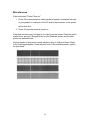
After receiving your printer, please check for possible shipping damage:
1. Inspect the outside of both the box and the printer for possible damage.
2. Open the top cover of the printer to see if the media compartments are in
order.
Note: If damage has occurred, contact your shipping company immediately to
file a claim.
3. Check whether you have received the following accessories together with
the printer. If there are any items missing, please contact your local dealer.
5
1
2
4
3
5
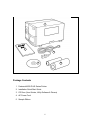
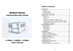
Package Contents
1. Fastmark 4600 PLUS Series Printer
2. Installation Quick Start Guide
3. CD Rom (User Guides, Utility Software & Drivers)
4. AC Power Cord
5. Sample Ribbon
6
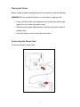
Placing the Printer
Before setting up and connecting the printer you should consider the following.
WARNING! Do not operate the printer in an area where it might get wet.
Find a solid flat surface with adequate room for the printer and enough
space above for media and ribbon access.
Place the printer within cable distance of the host and printer (serial or
parallel cable.)
Isolate the power cord from other electrical cables.
Connecting the Power Cord
Connect the power cord as below.
||
7
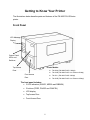
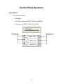
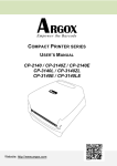
Getting to Know Your Printer
The illustrations below describe parts and features of the FM 4600 PLUS Series
printer.
Front Panel
LCD Message
Display
Control Panel
LED’s and
Switches
Top Access
Printer Models:
TIA-200V (FM 4602 PLUS / 203dpi)
Door
TIA-230E (FM 4602 PLUS / Int. Ethernet 203dpi)
Front Access
TIA-320 (FM 4603 PLUS / 300dpi)
Door
TIA-320E (FM 4603 PLUS / Int. Ethernet 300dpi)
The front panel includes:
3 LED indicators (READY, MEDIA and RIBBON)
3 buttons (FEED, PAUSE and CANCEL)
LCD display
Top Access Door
Front Access Door
8
LED Indicators
There are three LED indicators on the front panel, READY, MEDIA and RIBBON.
These indicators display the operation status of the printer.
READY
On – Normal operation
Off – Printer error
MEDIA
On – Normal operation
Blinking – Install new media
Printhead overheat
The printer is paused,
RIBBON
On – thermal transfer mode with ribbon installed
Off – direct thermal mode ( no ribbon installed )
Blinking – Install a new ribbon
For the FM 4602 PLUS Series, and the
FM 4603 PLUS Series models, modes of
thermal transfer and direct transfer can be set
via the printer panel or Utility software.
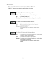
Buttons
There are three buttons, each with two basic functions.
Button
Function 1
(Press the button)
Function 2
(Press the button and
power switch together)
Feed a label
Perform self test & print
configuration report
PAUSE/
Pause printing
Perform a media calibration
CALIBR
Press again to resume printing
CANCEL/
Interrupt and delete a print task
RESET
Force printer to continue after an
error is solved.
FEED/
CONFIG
9
Reset FLASH settings
Notes:
1. You should perform a media calibration after installation and when
changing to a different type or size of media.
2. Before calibration, you must load the media and ribbon properly and move
the label sensor to the correct position avoiding holes.
3. After calibration the printer saves parameters to FLASH. Without correct
calibration gap detection is easily lost during printing especially for small
labels (less than 1.5 inches in height).
4. After self-test, the printer is in dump mode. For normal operation, you must
press CANCEL to restart the printer.
LCD Display
The FM 4600 PLUS Series models have a LCD that shows:
printer status
printer settings
input data from a keyboard or barcode reader
The first parameter is either 203 or 300, which stands for the print resolution. The
second parameter indicates the emulation (printer language), PAL/PPLZ, PPLA,
or PPLB.
After power-on, the LCD displays the following message as examples:
FM 4602 PLUS Series
(203, PAL/PPLZ)
FM 4603 PLUS Series
(300, PAL/PPLZ)
If a keyboard is plugged in, the display shows:
FM 4602 PLUS Series
(203, PAL/PPLZ)
<ESC> FOR KEYBD
10
FM 4603 PLUS Series
(300,PAL/PPLZ)
<ESC> FOR KEYBD
If a barcode reader is connected, the display shows:
FM 4602 PLUS Series
(203,PAL/PPLZ)
WITH B.C. READER
FM 4603 PLUS Series
(300,PAL/PPLZ)
WITH B.C. READER
If an abnormal condition occurs, a related message is displayed. For example:
RIBBON OUT
Setting Display Language
The printer’s LCD display supports six languages: English, French, German,
Italian, Spanish, and Portuguese.
To select a language:
1. Press the PAUSE and CANCEL buttons at the same time.
2. Hold both buttons for about 3 seconds and release.
3. The language selection screen appears.
LANGUAGE
ENGLISH
4. Press the FEED button for the next language.
5. Press the CANCEL button to select and set the language.
Press PAUSE or the PAUSE+CANCEL buttons to exit the language selection
screen and enter normal mode.
11
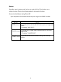
Changing Settings from the Panel
You may change settings using the front panel buttons of the FM 4600 PLUS
series printer models. In addition you may also change settings via software
Utility and data stream commands.
Buttons
FEED+PAUSE
FEED+CANCEL
Function
Press to enter setting mode.
(Don’t press over 1 second)
Press to show next features.
CANCEL
FEED+CANCEL
Press to select desired feature.
To scroll through the list of values for the
chosen feature.
CANCEL
PAUSE
To save the currently displayed value.
To exit setup mode.
Setting Procedure:
To change settings using the buttons on the front panel:
1. Press PAUSE, verify mode on LCD display.
2.
3.
4.
5.
Press FEED and PAUSE at the same time to enter setup mode.
Press and hold FEED, use CANCEL to scroll through the list of features.
Press CANCEL to select desired feature.
Press and hold FEED, use CANCEL to scroll through the list of values for
the chosen feature.
6. Press CANCEL to save the currently displayed value.
7. Press PAUSE twice to exit setup mode and READY the printer.
12
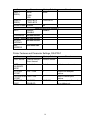
Basic Printer Features and Parameter Settings , PPLA/PPLB.
NOTE: Features can vary based on printer model. Do not change settings
during printing or communication.
Feature
PRINT MODE
Parameter
Thermal transfer /
Direct thermal
Factory Default
Thermal transfer
AUTO
CALIBRATE
MODE
CUT/PEEL
OFFSET
TPH VERTICAL
OFFSET
RECOVER
PRINT
CUTER
INSTALLED
PEELER
INSTALLED
READER
INSTALLED
WIN. CON. LIN.
Mode 1~4
Mode 1
Calibrates on demand.
-015 ~+.050
0
-.003~+.003”
0
ENABLED,
DISABLED
YES
NO
YES
NO
YES
NO
0~254
ENABLED
Controls cut and peel
position.
Offset of vertical print
position.
Contents reprint after media
out or ribbon-out.
BASE SEED
COUNTING
DOWN
NO
NO
NO
0
Only under Windows with
bundled printer driver and
continuous media.
0~4 ips
UP
DOWN
MEDIA
GAP
SENSOR TYPE BLACK BAR
0 ips
DOWN
BACKFEED
ENABLED
DISABLED
.0~040”
DISABLED
-028~+028
0
PRESENT
DISTANCE
BASE
DARKNESS
BAUD RATE
(RS232)
Remarks
GAP
.87”
600 / 1200 / 2400/ 9600
4800 / 9600 /
19200 /NONE
13
Select for media
characteristics. Once
changed make sure to
calibrate before printing.
Appears only when
BACKFEED enabled.
Feature
PARITY
(RS232)
Parameter
Factory Default
NONE
NONE
EVEN
ODD
LENGTH
8 DATA BITS
8 DATA BITS
(RS232)
7 DATA BITS
CLEAR FLASH YES/NO
NO
PRINTERS WITH ETHERNET
DHCP
ENABLE
ENABLE
DISABLE
IP ADDRESS
###.###.###.###
SUBNET MASK ###.###.###.###
DEFAULT
###.###.###.###
GATEWAY
MAC
####.####.####
ADDRESS
Remarks
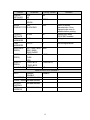
Printer Features and Parameter Settings, PAL/PPLZ
Feature
PRINT MODE
Parameter
Thermal transfer /
Direct thermal
Factory Default
Thermal transfer
AUTO
CALIBRATE
MODE
CUT/PEEL
OFFSET
TPH VERTICAL
OFFSET
RECOVER
PRINT
Mode 1~4
Mode 1
Calibrates on demand.
-015 ~+.050
0
-.003~+.003”
0
ENABLED,
DISABLED
ENABLED
Controls cut and peel
position.
Offset of vertical print
position.
Contents reprint after media
out or ribbon-out.
14
Remarks
Feature
PEELER
INSTALLED
COUNTING
Parameter
YES
NO
UP
DOWN
MEDIA
GAP
SENSOR TYPE BLACK BAR
PRESENT
DISTANCE
ABS
DARKNESS
TRIM
DARKNESS
BAUD RATE
(RS232)
Factory Default
NO
Remarks
DOWN
GAP
.0~040”
.87”
0~30
0
Select for media
characteristics. Once
changed make sure to
calibrate before printing.
Appears only when
BACKFEED enabled.
Setting darkness
-30~30
0
Fine-tuning darkness
600 / 1200 / 2400/ 9600
4800 / 9600 /
19200 /NONE
PARITY
NONE
NONE
(RS232)
EVEN
ODD
LENGTH
8 DATA BITS
8 DATA BITS
(RS232)
7 DATA BITS
CLEAR FLASH YES/NO
NO
PRINTERS WITH ETHERNET
DHCP
ENABLE
ENABLE
DISABLE
IP ADDRESS
###.###.###.###
SUBNET MASK ###.###.###.###
DEFAULT
###.###.###.###
GATEWAY
MAC
####.####.####
ADDRESS
15
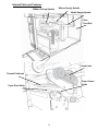
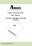
Internal Parts and Features
Ribbon Pick-up Spindle
Ribbon Supply Spindle
Media Supply Spindle
Rear
Feed Slot
Head Latch
Thermal Printhead
Paper Sensor
Guide
Paper Drive Roller
16
Peeler Option
Cutter Module
17
Loading Ribbon and Media
This section describes how to load ribbon and media.
Loading a Ribbon
Note: This section can be referred to, when transfer thermal printing is used.
The steps below are based on ribbon wound ink-side in as an example.
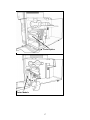
1. Lift the top cover and front access door to expose the media compartment.
(Figure 1)
1
Front Access
18
2. Turn the head latch counter-clockwise and open the bracket. (Figure 2)
2
Head
Latch
Bracket
3. Unwrap the ribbon and separate the ribbon roll from the bare core. Insert
the ribbon roll onto the ribbon supply spindle. (Figure 3)
3
Ribbon Supply
Spindle
19
4. Lead the ribbon through the print head module. (Figure 4)
5. Attach the edge of the ribbon onto the bare core and wind it a bit onto the
core. Make sure the coating side of the ribbon is face down.
4
Print
Head
Module
Bar Core
6. Insert the core onto the ribbon pick-up spindle. (Figure 5)
5
Ribbon
Pick-up
Ribbon Pick-up
Spindle Spindle
7. Turn the pick-up spindle to ensure the ribbon is tightly wound.
20
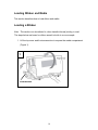
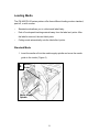
Loading Media
The FM 4600 PLUS series printers offer three different loading modes: standard,
peel-off, or with a cutter.
Standard mode allows you to collect each label freely.
Peel-off mode peels backing material away from the label as it prints. After
the label is removed, the next label prints.
Cutting mode automatically cuts the label after it prints.
Standard Mode
1. Insert the media roll into the media supply spindle and move the media
guide to the inside. (Figure 6)
6
Media
Guide
Media Supply
Spindle
21
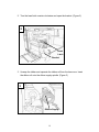
2. Turn the head latch counter-clockwise and open the bracket. Remove the
outside media guide. (Figure 7)
7
Head
Latch
Outside
Media
Guide
Bracket
22
3. Lead the media through the print head module and under the paper
sensor guide. (Figure 8)
8
Print Head
Module
Paper Sensor
Guide Module
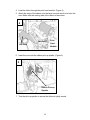
4. Return the outside media guide, close the bracket, and hook the head
latch. (Figure 9)
9
Head
Latch
Bracket
Outside Media Guide
23
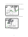
5. Close the top cover and the front access door and turn on the printer, or
press the “FEED” button if the printer is already on. (Figure 10)
10
24
Peel Off Mode
Follow steps 1 to 3 in “Loading the Media – Standard Mode” above.
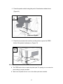
1. From the leading end of the media roll remove enough labels to expose
6-inches of backing/liner. (Figure 11)
11
Backing Paper
Remove labels
25
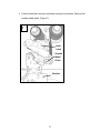
2. Lead the media backing/liner through the print head module. (Figure 12)
12
1
Media Backing/Liner
1
Print Head
Module
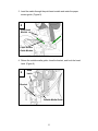
3. Push down the peel-off mechanism release lever and lead the media
backing/liner under the peeler module. (Figure 13)
13
1
1
Dispenser
Module
Peel Lever
Media Backing/liner
26
4. Close the peeler module using the peel-off mechanism release lever.
(Figure 14)
14
Peel Lever
Dispenser Module
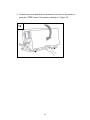
5. Close the top access door and turn on the printer or press the FEED
button if the printer is already on. (Figure 15)
15
1
1
Media
Backing/Liner
Notes:
The FEED button does not make the printer peel. For peeling to occur when the
panel setting is properly enabled.
Make sure the peeler sensor is out of the ribbon path when installed.
27
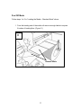
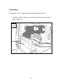
Cutting Mode
Follow steps 1 to 3 in “Loading the Media – Standard Mode” above.
1. Insert the media into the print head module and under the paper sensor
guide. (Figure 16)
16
Cutter Module
Print Head Module
Paper Sensor Guide
28
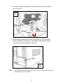
2. Return the outside media guide, close the bracket, and hook the head
latch. (Figure 17)
17
81
1
Head
Latch
Bracket
Outside Media Guide
3. Close the top access door and turn on the printer or press the FEED
button if the printer is already on. The printer will then feed the labels
through the cutter automatically. (Figure 18)
Cutter
18
Note:
The FEED button does not make the printer cut. For cutting to occur when the
panel setting is properly enabled.
29
Control Panel Operation
Front Panel
The front panel includes
-
LCD display
-
3 LED status indicators (READY, MEDIA and RIBBON)
-
3 control buttons (FEED, PAUSE and CANCEL)
LCD display
LED indicators
Control buttons
30
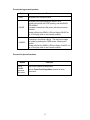
LED Indicators
There are three LED indicators on the front panel, “READY”, “MEDIA” and
“RIBBON”. These indicators display the present status of the printer.
The Ready LED indicates the following conditions:
READY
ON
- The printer's power is on, unit is ready to print.
Off
- The printer's power is off.
Blinking - Error condition (see Troubleshooting section for details)
The Media LED indicates the following conditions:
MEDIA
ON
- Media is installed and ready for Normal operation.
Off
- The printer's power is off.
Blinking - Media Out condition.
This condition only occurs following a media motion
request.
The Ribbon LED indicates the following conditions:
RIBBON
ON
OFF
- The printer is set for Thermal Transfer mode and the printer
contains a Thermal Transfer Ribbon.
- The printer is set for Direct Thermal Mode.
Blinking - The printer is set for Thermal Transfer mode and the ribbon
is not moving or at end of life.
This condition only occurs following a media motion
request.
31
Buttons
Depending upon the printer model and current mode, the Front Panel buttons serve
multiple functions. Refer to the following tables for their specific functions.
Pressed and held down during Power UP
Upon completion of the desired function the printer will go into a READY condition.
Button
FEED/CONFIG
PAUSE/CALIBR
CANCEL/RESET
Function
The printer performs an internal Self-Test and prints a Configuration
Report.
LCD displays "SELF TEST".
The printer will do a Label Sensor Calibration test on the current
loaded media.
LCD displays "CALIBRATION".
The printer will reset the Non-Volatile memory back to factory
defaults.
32
Pressed during normal operation
Button
Function
FEED
The printer will Feed a one label.
PAUSE
The printer will begin blinking the READY LED.
If printing the printer will STOP printing, and the READY
LED will blink.
If pressed a second time the printer will resume normal
operation.
Models will blink the READY LED and display PAUSE on
the LCD display while in the Paused condition.
CANCEL
The printer will Stop printing and delete any further
information in the printer's buffer. The user must realign
the media by pressing the FEED button, following this
function.
Models will blink the READY LED and display CANCEL on
the LCD display while in the Paused condition.
Pressed for Special functions
Button
FEED
PAUSE
(RELEASE
BUTTONS)
Function
Enter into the printer's Setup menu.
See the Front Panel Setup Menu section for more
information.
33
LCD Display
The front panel is equipped with a 2 row by 16-character display.
The basic function of the display is:
-
Display the printer status
-
Display the printer settings
-
Display's prompts requesting input data from a keyboard or barcode reader.
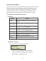
Standard Printer
After power ON the following message is displayed on the LCD
(203, PAL/PPLZ)
The first parameter is either 203 or 300. It indicates the print resolution.
The second parameter indicates the emulation (printer language), PAL/PPLZ, PPLA
or PPLB.
With Keyboard Option installed
If a keyboard is plugged in and PAL app loaded, the following message is displayed
on the LCD
(203, PAL/PPLZ)
<ESC> FOR KEYBD
With Barcode Reader Option
If a barcode reader is connected and PAL app loaded, the following message is
displayed on the LCD.
(203, PAL/PPLZ)
WITH B.C. READER
Abnormal Conditions
If any abnormal condition occurs the related message will be displayed. For
example:
RIBBON OUT
34
Front Panel Set-up Menu
The Set-up menu is a list of printer features that affect the basic operation of the printer.
These are functions that may not normally be selected using software commands.
Value settings that are changed using the keypad are stored into memory and are
retained when power is cycled. Value settings that are changed using software
commands are temporary changes and are not retained when power is cycled.
LCD and Button functionality in Set-up mode
Set-up Mode
Buttons
PAUSE
Function
Press PAUSE to take printer off- line with READY LED
blinking.
FEED + PAUSE Enters into set-up mode and displays feature.
(release buttons)
FEED + PAUSE
Press and hold down FEED button. Press PAUSE button
repeatedly to scroll to the next feature.
FEED + CANCEL
Press and hold down FEED button. Press CANCEL button
repeatedly to scroll to the previous feature.
CANCEL
Pressing this key will select the displayed feature.
FEED + PAUSE
Press and hold down FEED button. Press PAUSE button
repeatedly to scroll to the next value.
CANCEL
Pressing this key will select the displayed value.
PAUSE
Press PAUSE twice to exit set-up mode and ready printer.
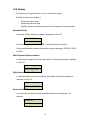
LCD Displayed Information
Below is an example of a typical displayed Feature.
PRINT MODE
DIRECT THERMAL
*
Feature name: PRINT MODE (blinking when selected)
Feature Value: DIRECT THERMAL (chosen print mode)
Stored indicator: * (selected and saved)
35
Procedure to Enter into Set-up Mode
1.
Power on the printer.
2.
When the “ READY” message is displayed on the LCD, press [PAUSE] once
to enter off-line mode. Press and hold [FEED] and then [PAUSE] buttons.
Release buttons.
3.
Press and hold [FEED], then press [PAUSE] button repeatedly to scroll to
the feature that you want to change.
4.
Press [CANCEL] button once to select feature.
5.
Press and hold [FEED], then press [PAUSE] button repeatedly to scroll to
the desired value of the displayed feature.
6.
Once the desired value is displayed, press [CANCEL] button to save it.
After pressing the [CANCEL] button an * should appear in the last column.
The * is used to designate the stored value in non-volatile memory.
7.
Press the [PAUSE] button once to save, and again to return to normal
mode.
Note: Do not enter set-up mode while the printer is printing or while the host is
sending data.
36
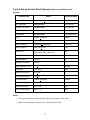
Typical Set-up Control Panel Features (features may differ among
models)
Feature Item
Value
Factory Default
PRINT MODE
Direct Thermal or Thermal Mode
Direct Thermal
MAC ADDRESS
####-####-####
Printer Specific
DEFAULT GATEWAY
###.###.###.###
Printer Specific
SUBNET MASK
###.###.###.###
Printer Specific
IP ADDRESS
###.###.###.###
Client Determined
DHCP
Enabled or Disabled
Disabled
CLEAR FLASH
Yes or No
No
LENGTH (RS232)
7 Data Bits or 8 Data Bits
8 Data Bits
PARITY (RS232)
None Odd or Even
None
BAUD RATE
9600 / 115200 / 57600 / 38400 / 19200
9600 / 4800 / 2400 / 1200 / 600
9600
TRIM DARKNESS
-030 ~ +030
+000
ABS DARKNESS
000~030
016
PRESENT DISTANCE
000~040
021
MEDIA SENSOR TYPE
Gap or Black Bar
Black Bar
COUNTING
Up or Down
Down
PEELER INSTALLED
Yes or No
No
CUTTER INSTALLED
Yes or No
No
RECOVER PRINT
Enabled or Disabled
Disabled
TPH VERT. OFFSET
-003 ~ +003
+000
CUT PEEL OFFSET
-015 ~ +050
+000
AUTO CALIBR MODE
Mode 1 ~ 4
Mode 1
Notes:
1. To verify that a feature has been properly changed cycle power on the printer.
2. Make sure the settings you desire has an * character by the value.
37
PALTM Print and Program Overview
Printers featuring PALTM Print and Program ability can be used in several ways in
any given environment. This section describes 3 common ways this advanced
capability is used. For help and assistance determining the best way to use this
ability in your situation, please consult your sales representative.
Traditional Printing
This environment represents the most common use of printers. Generally a
single print job (PALTM print sequences) generates a single label. In this role the
PALTM Print and Program interpreter accepts the print job, performs the required
operator processing and prints the; label, tag, or ticket. Using a Windows driver
in conjunction with a Windows application program is a typical way to print in this
environment. Alternatively, PALTM print sequences may also be generated by
any host application written to take advantage of this powerful language.
When a PALTM capable printer is used this way, no special “PALTM program” must
be loaded on the printer. Print sequences generated by a Windows driver or host
program are simply sent to the printer resulting in print output just like traditional
printers.
Legacy Data Stream Interpretation
PALTM Print and Program capable printers uniquely address applications where
upgrading to modern cost effective technology is desired. Often cost-prohibitive
software reprogramming to change a data stream prevents an organization from
moving to new printing technologies.
38
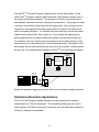
Using a PALTM Print and Program capable printer solves this problem. In this
case a PALTM program is written which interprets a data stream normally sent to
the legacy device being replaced. This program is stored on the printer and is
automatically executed each time the printer is powered on. This program is able
to produce a new label format based on this legacy data. Even though the host
computer is sending the exact same legacy data to the printer, the label format
can be completely different. For example the new format may include bar codes,
scaled and/or rotated fonts, lines, logo's etc. Even though the legacy device
being replaced does not support these print abilities, the new label format can.
For example, text only outputs such as produced by a dot-matrix printer or card
embosser may now be presented in a more functional format. Information in the
data stream can be reformatted into any size font in any rotation, or even printed
as bar code. This example demonstrates how PALTM Print and Program capable
PAL Data Stream
Application
Legacy Data
Stream
PAL
Interpreter
Printer
Flash Memory
Printed
Document
Legacy Data
Stream
Host System
PAL Printer
printer can replace a legacy print device with no host software changes required.
Standalone/Downtime Applications
PALTM Print and Program capable printers may be programmed to operate
independent of a PC/host connection. This standalone ability may be used in
cases where no PC/host connection is needed or as a fail-safe backup when the
PC/host or network is unavailable.
39
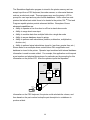
The Standalone Application program is stored in the printer memory and can
accept input from a PS/2 keyboard, bar code scanner, or other serial devices
such as an electronic scale. These programs may use the printer’s LCD to
prompt for user input and may also include databases. Unlike other bar code
printers that allow basic static forms to be loaded in the printer, PAL TM Print and
Program capable printers provide advanced abilities. Examples of these
advanced capabilities are:
Ability to operate on line from host or off line in stand-alone mode
Ability to range check user input
Ability to combine data from multiple fields into a single bar code
Ability to access database stored in printer
Ability to perform math calculations (addition, subtraction, multiplication,
division, etc.)
Ability to perform logical calculations (equal to, less than, greater than, etc.)
Shown below is an example where a stand-alone PALTM application and
database is stored in the printer. Operator input combined with internal database
information is used to create a label. For example, this application could request
a part number and physical dimensions of a particular part by prompting for this
information on the printer LCD. After the operator inputs the requested
Local
Database
PAL Standalone
Application
Keyboard Data
PAL
Interpreter
Printer
Flash Memory
Printed
Document
Operator
Input
PAL Printer
Keyboard
information on the PS/2 keyboard, the printer could calculate the volume, and
then based on the part number lookup the part description in a database to
produce a label.
40
Calibration & Configuration
This section discusses calibration, printing configuration and resetting the printer
to factory defaults.
Performing Calibration
After the media is loaded, please perform media calibration to calibrate the label
sensor in advance.
1. Turn off the printer
2. Press and hold the PAUSE button and turn on the power.
3. When “CALIBRATION …” is displayed on the LCD , and both READY and
MEDIA indicators blink, release the PAUSE button.
NOTE: Printers with Ethernet will take 20 second for this process,
the PAUSE button must be pressed during that period.
4. The printer feeds 12-inches of blank labels.
5. When “READY” is displayed, the READY and MEDIA indicators stop
blinking but remain illuminated.
Important! It’s recommended to perform media calibration after changing media.
Failure to do so could result in improper detection by the label sensor.
41
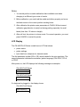
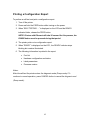
Printing a Configuration Report
To perform a self-test and print a configuration report:
1. Turn off the printer.
2. Press and hold the FEED button while turning on the power.
3. When “SELF-TESTING …” is displayed on the LCD and the READY
indicator blinks, release the FEED button.
NOTE: Printers with Ethernet will take 20 second for this process, the
PAUSE button must be pressed during that period.
4. The printer prints out a configuration report.
5. When “READY” is displayed on the LCD , the READY indicator stops
blinking but remains illuminated.
6. The following information is printed in the report:
Font list
Hardware configuration and status
Label parameters
Firmware version
Notes:
After the self-test the printer enters the diagnosis mode (Dump mode). To
continue to normal operation, press CANCEL button to cancel the diagnosis mod
(Dump mode).
42
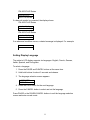
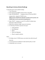
Resetting to Factory Default Settings
To reset the printer to factory default settings:
1. Turn off the printer.
2. Press and hold the CANCEL button and turn on the printer.
3. When “E2PROM RESET …” is displayed on the LCD and the READY
indicator blinks, release the CANCEL button.
NOTE: Printers with Ethernet will take 20 second for this process, the
PAUSE button must be pressed during that period.
4. When “READY” is displayed on the LCD, the READY indicator stops
blinking but remains illuminated.
5. When the two indicators relight, release the feed button.
6. The following information is printed in the report:
Label parameters
Heat (Darkness)
Speed
Symbol set (language)
Others for specific emulation
Notes:
1. All settings stored in FLASH memory are retained even after turning off
the printer.
2. You must perform the calibration for label sensitivity after you reset.
3. Printed label count is not reset.
43
Computer Connections
This printer comes with USB interface, a standard Centronics parallel interface,
and a nine-pin Electronics Industries Association (EIA) RS-232 serial data
interface.
USB Interface Requirements
The Universal Serial Bus (USB) interface is version 2.0 and 1.1 compliant and
provides a full-speed (12Mb/s) interface that is compatible with your existing PC
hardware. The USB’s “plug and play” design makes installation easy. Multiple
printers can share a single USB port/hub.
Centronics Parallel Port
You can connect the printer to the host computer’s parallel port using any
standard Centronics cable. The required cable must have a standard 36-pin
parallel connector on one end, which is plugged into the parallel port located on
the back of the printer. The other end of the parallel interface cable connects to
the printer connector at the host computer. For pin-out information, please refer
to the Technical Reference in this manual.
44
Serial (RS-232) Port
The required cable must have a nine-pin "D" type male connector on one end,
which is plugged into the mating serial port located on the back of the printer. The
other end of the cable connects to a serial port on the host computer. For
technical and pin-out information, please refer to the Technical Reference in this
manual.
Note:
1. Centronics allows a much higher communication speed than serial.
2. The pin assignment of serial cable is different from PC.
Please contact your local reseller if you need
this cable.
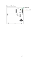
Ethernet 10/100 Internal Printer Server Option
This connector is for Ethernet application; it is convenient to use several printers
by Ethernet connector at the same time.
Note:
When using Ethernet model printer, please wait till the
Ready Indicator to stop blinking, before starting printer
operations.
45
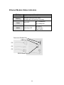
Ethernet Module Status Indicators
LED Status
Both Off
Blinking
Green
Amber
Description
No Ethernet link detected.
The printer waits for printer ready.
It will take about 20 seconds to be ready.
On: 100 Mbps link
Speed LED
Off: 10 Mbps link
Link/Activity LED
Centronics Parallel Port
USB Port
PC
PC
PC
RS232 Serial Port
46
On: link up
Off: link down
Flash: activity
Ethernet LED Indicators
Green LED
Amber LED
47
Communicating with the Printer
The bundled printer driver can be applied to all applications under Windows
2000/ 2003/ XP/ Vista/ Windows 7, supporting 32-bit/ 64-bit operation systems.
With this driver you can operate any popular Windows software applications
including Bartender editing software or MS Word, etc., to print to this printer.
The screens included for these steps are taken from Windows XP; steps in other
versions of operation systems are similar.
Note:
We strongly recommend that you use the Seagull Driver
Wizard instead of the Microsoft Windows Add Printer Wizard
when installing and updating your Drivers by Seagull.
(Even though the "Add Printer Wizard" is from Microsoft, it
too easily performs a number of tasks incorrectly when
updating existing drivers. It also badly handles the situation
where a printer driver is already in use by a Windows
application.)
48
1. Turn off the printer. Plug the power cable into the power socket on the wall,
and then connect the other end of the cable to printer's power socket.
Connect an interface cable (i.e USB, Parallel or Serial) from the printer to the
PC.
2. Turn on the printer. If the printer supports Plug-and-Play, and you have
successfully connected it using a USB cable, then the Windows Add
Hardware Wizard will automatically detect the printer and display a dialog that
allows you to install a driver. Click Cancel and do not install the driver using
the Windows Add Hardware Wizard. Instead use the Seagull Driver
Installation Wizard provided on the CD ROM received with your printer.
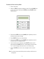
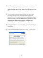
3. Utilizing the CD ROM from your printer package, select and start the Seagull
Driver Wizard.
4. On the prompt, Windows Printer Driver, select “I accept…” and click "Next".
49
5. Assign the directory to keep Seagull driver, (for example: C:\Seagull) and click
"Next".
6. Click "Finish".
50
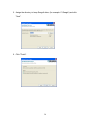
7. Select Install printer drivers and Click "Next"
8. Select model & emulation :
TIA-230
TIA-230E
TIZ-230
51
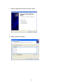
9. Select the port of the printer and click "Next".
10. Enter Printer name and select "do not share this printer”, and click "Next".
Argox X-3200 PPLB
52
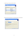
11. Check all the data on the showing screen, if it is correct, click "Finish".
Not Shared
LT1
YES
TIA-230E
7.1.8_M-0
12. After the related files have been copied to your system, click "Finish".
53
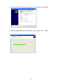
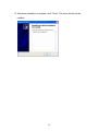
13. After driver installation is complete, click "Close". The driver should now be
installed.
Installed printer TIA-230E PPLB
54
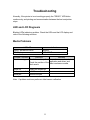
Troubleshooting
Normally, if the printer is in not working properly, the "READY" LED blinks
continuously, and printing and communication between the host and printer
stops.
LED and LCD Diagnosis
Blinking LEDs indicate a problem. Check the LEDs and the LCD display and
refer to the following solutions:
Media Problems
LED/LCD
READY and MEDIA LEDs
LCD Display
Indication
Blinking
MEDIA OUT
Possible Problems
Solutions
Remarks
Mis-detected gap Check the media path
For continuous media, check
Check the position of the application and driver, and
select continuous media.
label sensor
Media out
Supply the media roll
Media not installed Install the media roll
Media jam
Recover the jam
Note: If problem continues perform a label sensor calibration.
55
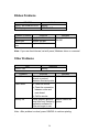
Ribbon Problems
LED/LCD
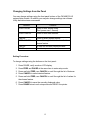
READY and RIBBON LEDs
LCD Display
Indication
Blinking
RIBBON OUT
Possible Problems
Solutions
Ribbon out
Supply the ribbon roll
Ribbon jam
Recover the jam
Ribbon sensor
Replace ribbon sensor
error
Remarks
Not applicable to direct
thermal.
Note: If you use direct thermal, set with panel, Windows driver or command.
Other Problems
LED
READY LED
Problems
Serial IO error
Cutter failed
Indication
Blinking
Solutions
Remarks
Check the baud rate,
Not for Centronics
format or protocol
between host and printer
Check the media.
Check the connection
between cutter and
main board.
Call for service.
Memory full
Check graphics and soft Need to reboot the
fonts from host. Delete by system.
application software for
those no longer in use.
Note: After problem is solved, press CANCEL to continue printing
.
56
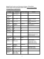
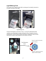
Light /Missing Print
Print quality can be adjusted when light or missing print is primarily observed on
the right or left side of the media.
Figure 1
Figure 2
Light/Missing Print
If the print discrepancy is as shown in Fig. 1, turn the Fine Adjustment Knob
clockwise one setting (adjust counter clockwise for Fig. 2 correction), then try
printing again to justify the print quality improvement. Repeat the same process
until the print quality is well balanced on both sides of the label.
Figure #1, Light Print Correction
Adjust Clockwise
Fine Adjustment
Knob
4
6
2
0
2
4
6
Figure #2, Light Print Correction
Adjust Counter Clockwise
57
Miscellaneous
If the host shows "Printer Time out"
1. Check if the communication cable (parallel or serial) is connected securely
to your parallel or serial port on the PC and to the connector on the printer
at the other end.
2. Check if the printer power is turned on.
If the data has been sent, but there is no output from the printer. Check the active
printer driver, and see if Seagull Driver for your Windows system and the label
printer has been selected.
Vertical streaks in the printout usually indicate a dirty or faulty print head. (Refer
to the following examples.) Clean the print head. If the problem persists, replace
the print head.
58
For unstable ribbon roll rotation, check the label path and make sure the head
latch is securely closed.
Poor printout quality:
The ribbon may not be qualified.
The media may not be qualified.
Adjust the Darkness (heat temperature).
Slow down the print speed.
Refer to the following and clean the related spare parts.
Recovery
After correcting problems, simply press the CANCEL button or restart the printer.
Make sure the LED’s are not blinking and remember to resend your files.
59
Caring for Your Printer
Clean the following components of the printer using a cotton bud dampened with
alcohol. Do not soak the cotton bud excessively.
Note: Turn off the printer before cleaning.
Cleaning the Print Head
Clean the print head as follows
1. Turn off the printer.
2. Open the top cover to access the print head module
3. Remove the ribbon.
4. Rub the print head with a cotton bud moistened with alcohol.
5. Check for any traces of black coloring or adhesive on the cotton after
cleaning.
6. Repeat if necessary until the cotton is clean after it is passed over the
head.
Note: Clean the print head every time the ribbon is replaced or more often
depending on actual usage and conditions.
60
Cleaning the Roller
Using a cotton bud moistened with alcohol, clean the roll and remove any
attached glue.
Note: Clean the roller after it has been in contact with foreign materials such as
dust or adhesives.
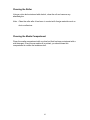
Cleaning the Media Compartment
Clean the media compartment with a cotton bud that has been moistened with a
mild detergent. Every time a media roll is printed, you should clean this
compartment to reduce the incidence dust.
61
Technical Reference
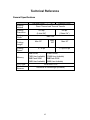
General Specifications
FM 4602 PLUS
Printing
Method
Printing
Resolution
Printing
Speed
Memory
CPU Type
Media
Sensors
IE
FM 4603 PLUS
Direct Thermal and Thermal Transfer
203 dpi
(8 dots/.04”)
Printing
Width
Printing
Length
/
300 dpi
(12dots/.04”)
Max 4.09”
Max.
100”
Max. 50”
2 ~ 6 ips
Max. 50”
1 ~ up to 5 ips
8MB DRAM
16 MB DRAM
(7MB User Available) (13MB User Available)
4MB Flash ROM
8MBFlash ROM
(3MB User Available) (6MB User Available)
32 bit RISC CPU
Reflective & See-through (movable)
62
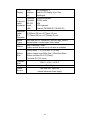
Display
LED
indicator
x3
Communi
cation
interfaces
Centronic
s parallel,
RS-232
serial,
USB
Maximum
Label
Roll
Diameter
Media
Types
Ribbon
Ribbon
Size
Compact
Size
Weight
Power
Source
LED indicator x 3,
Back-lit LCD Display 16 x 2-line,
Multilingual
Centronics parallel,
RS-232 serial,
USB,
PS/2 keyboard
Ethernet (FM 4602 IE / FM 4603 IE)
8”(203mm) OD on a 3”(76mm) ID core
7”(178mm) OD on a 1.5”(38mm) ID core
Roll-feed, die-cut, continuous, fan-fold, tags, ticket in
thermal paper or plain paper, fabric labels
Wax, Wax/Resin, Resin
(ribbon wound ink-side out or ink-side in available)
Ribbon width: 1”~4”(25.4 mm~101.6 mm)
Ribbon Length: max 360m Wax, 300m Semi-Resin
Ribbon roll max OD 2.75“(70mm)
Core size ID 1”(25.4 mm)
W9.8” x L16.5” x H10.4”
24lbs(11kgs)
100~240 VAC, 50/60 Hz,
internal universal power supply
63
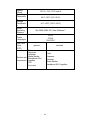
Agency
Listing
Operating
Temperatur
e
Storage
Temperatur
e
Driver
Operating
Systems
CE, UL, CUL, FCC class A
40F~100F (4C~38C)
-4F~122F (-20C~50C)
Win 2000/ 2003/ XP/ Vista/ Windows 7
PPLA,
PPLB
PAL/PPLZ
Printer
Languages
Real Time
Clock
(RTC)
Options and
Accessories
optional
standard
Cutter
Dispenser
Rewinder
Media Stacker
Standalone KDU:
ArgoKee
RTC
Font card
Cutter
Dispenser
Rewinder
Media Stacker
Standalone KDU: ArgoKee
64
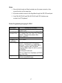
Fonts, Bar Codes and Graphics Specification
The specifications of fonts, bar codes and graphics depends on the printer
emulation. The emulation is a printer programming language through which the
host can communicate with your printer. There are three printer programming
languages, PPLA, PPLB and PAL/PPLZ.
Printer Programming Language A, PPLA
Specification
FM 4600 PLUS Series
General Fonts
7 alpha-numeric fonts, OCR A and OCR B
ASD Smooth
Fonts
4, 6, 8, 10, 12, 14, and 18 points
Symbol Sets
(Code Pages)
USASCII, UK, German, French, Italian,
Spanish, Swedish and Danish/Norwegian
Courier Fonts
8 symbol sets (PC, PC-A, PC-B, EAMA94, Roman, Legal, Greek and Russian)
Soft Fonts
Downloadable PCL fonts
Font
Expandability
1x1 to 24x24
Bar Code Types Code 39 , Code 93,
Interleaved 2of 5 (standard/with
checksum digit/with human readable
check digit), EAN-8, EAN-13,UPC-A,
UPC-E, Postnet, Codabar, Code 128
subset A/B/C,
UCC/EAN-128, UCC/EAN-128 K-MART,
UCC/EAN-128 Random Weight, Plessey,
HBIC, Telepen, FIM, UPC2, UPC5,
GS1 Data Bar
Graphics
PCX, BMP, IMG, and HEX formats
Stand-alone
Operation
ArgoKee
65
Printer Programming Language B, PPLB
Specification
General Fonts
Symbol Sets
(Code Pages)
FM 4600 PLUS Series
5 fonts with different point sizes
8 bits: code page 437, 850, 852, 860,
863, and 865
7 bits: USA, British, German, French,
Danish, Italian, Spanish, Swedish and
Swiss.
Downloadable soft fonts
1x1 to 24x24
Soft Fonts
Font
Expandability
Bar Code Types Code 39(checksum), Code 93, Codabar,
Interleave 2 of 5(checksum), Matrix 25,
UPC A/E 2 and 5 add-on, EAN-8/13,
Code 128UCC, UCC/EAN, Postnet,
German Postcode. MaxiCode and
PDF417 (2D symbologies)
Graphics
PCX and binary raster
Stand-alone
connect with PC keyboard or barcode
Operation
reader (PS/2 interface)
66
Notes:
1. Since the font board and flash modules use the same connector, they
cannot function at the same time.
2. All printer models connect to the ArgoKee through the RS-232 serial port.
3. Only FM 4602 PLUS and FM 4603 PLUS with PS/2 interface can
connect to a PC keyboard.
Printer Programming Language Z, PPLZ
Specification
General Fonts
International
Character Sets
FM 4600 PLUS Series
10 resident fonts (9 bitmapped fonts and 1
scalable fonts)
14 international character sets: USA, USA2,
UK, Holland, Den / Nor, Swe / Fin, German,
France1, France2, Italy, Spain, Misc.,
Japan, page 850.
Downloadable soft fonts
1x1 to 24x24
Soft Fonts
Bitmapped Font
Expandability
Bar Code Types One-Dimension barcode:
Code 11, Interleaved 2 or 5 (standard,
industrial) , Code 39, Code 128 (A, B&C),
Codabar, Logmars, MSI, UPC/EAN
extension EAN-8, EAN-13, UPC-A, UPC-E
and PostNet
Two-Dimension barcode:
PDF-417, MaxiCode, Data Matrix (ECC200
only), QR Code
Graphics
HEX and binary graphics with normal as
well as compressed image
67
Interface Specifications
This section presents the interface specifications of IO ports for the printer. These
include pin assignments, protocols and detailed information about how to
properly interface your printer with your host or terminal.
USB
2
1
3
4
USB series “B” Receptacle Interface
Pin
1
2
3
4
Signal
Name
VBUS
DD+
GND
Connector Terminal Pin Assignment
68
Serial Interface
The RS-232 connector on the printer side is a female, DB-9.
Pin
1
2
3
5
6
7
8
9
Direction
In
In
Out
Out
Out
In
Out
Definition
DSR
RxData
TxData
Ground
DTR
RTS
CTS
+5V
Note: Pin 9 is reserved for a KDU (keyboard device unit). Do not connect this pin
if you use a general host such as a PC
.
69
Connection with Host:
Host 25S
Printer 9P
Host 9S
(PC or compatible)
Printer
9P
(PC or compatible)
DTR 20 …… 1 DSR
DSR 6 …… 6 DTR
TX 2
…… 2 RX
RX 3
…… 3 TX
CTS 5 …… 7 RTS
RTS 4 …… 8 CTR
GND 7 …… 5 GND
DTR 4
DSR 6
TX 3
RX 2
CTS 8
RTS 7
GND 5
…… 1 DSR
…… 6 DTR
…… 2 RX
…… 3 TX
…… 7 RTS
…… 8 CTS
…… 5 GND
Alternatively you can connect the 3 wires as follows:
Host 25S
Printer 9P
Host 9S
(PC or compatible)
Printer
9P
(PC or compatible)
TX 2
…… 2 RX
RX 3
…… 3 TX
GND 7 …… 5 GND
pin 4
pin 5
pin 6
pin 20
TX 3
RX 2
GND 5
pin 4
pin 6
pin 7
pin 8
…… 2 RX
…… 3 TX
…… 5 GND
70
The simplest way to connect to other hosts (not PC compatible) or terminals is:
Printer
Pin 2- RxData ………
Pin 3- TxData ………
Pin 5- Ground ………
Terminal/Host
TxData
RxData
Ground
In general, as long as the data quantity is not too large and you use Xon/Xoff as
flow control, it will be problem free.
Baud rate:
1200, 2400, 4800, 9600(default), 19200, 38400, 57600,115200
bauds. (Programmable by command)
Data format: always 8 data bits, 1 start bit and 1 stop bit.
Parity:
Handshaking:
always non parity
XON/XOFF as well as CTS/RTS (hardware flow control).
If you run an application with the bundled printer driver under
Windows and use the serial port, you should check the above parameters and
set the flow control to "Xon/Xoff "or "hardware".
71
Parallel (Centronics)
The parallel port is a standard 36-pin Centronics connector. Pin assignments are
as follows:
Pin Direction
1
In
2
In
3
In
4
In
5
In
6
In
7
In
8
In
9
In
10
Out
11t
Out
12
Out
Definition
/STROBE
Data1
Data 2
Data3
Data4
Data5
Data6
Data7
Data8
/ACK
BUSY
PE
Pin
Direction
13
Out
14,15
16
17
18
19~30
31
32
Out
33~36
-
Definition
SELECT
NC
Ground
Ground
Ground
NC
/Fault
NC
Auto Polling
Both the serial port and parallel port of this printer can be active at the same
time, i.e. the printer can simultaneously communicate with two PCs via different
ports. However as no port contention is made for this printer, if both PCs transmit
data at the same time the data may become damaged in the receiving buffer.
72
Ethernet Interface
The following port complies with Ethernet communication.
Pin
1
2
3
4
5
6
7
8
Signal
Transmit+
TransmitReceive+
Reserved
Reserved
ReceiveReserved
Reserved
73
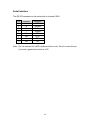
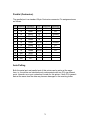
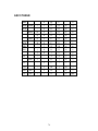
ASCII TABLE
NUL
0
@
P
'
P
!
1
A
Q
a
q
"
2
B
R
b
r
#
3
C
S
c
s
$
4
D
T
d
t
%
5
E
U
e
u
ACK
&
6
F
V
f
v
BEL
‛
7
G
W
g
w
BS
(
8
H
X
h
x
)
9
I
Y
i
y
*
:
J
Z
j
z
+
;
K
[
k
{
FF
,
<
L
\
l
I
CR
-
=
M
]
m
}
SOH
XON
STX
XOFF
NAK
LF
ESC
SO
RS
.
>
N
^
n
~
SI
US
/
?
O
_
o
DEL
74
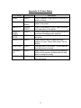
Appendix A: Printer Status
LCD display
PAUSE
MEDIA OUT
RIBBON OUT
Blinking LED
Description
READY
Printer is paused. Press PAUSE or CANCEL to
return to normal.
MEDIA
Media is uninstalled or used up. Load new
media to the printer.
READY
RIBBON
READY
READY
SERIAL IO
ERROR
CUTTER
READY
FAILED
MEMORY FULL READY
HEAD OPEN
READY
P. SENSOR
O.R.
READY
TPH TOO HOT MEDIA
Ribbon is uninstalled or end-of-ribbon occurred.
Load new ribbon to the printer.
Format or baud rate of RS232 communication is
inconsistent between printer and host.
Cutter cannot cut off the media, check media
and cutter.
Printer buffer full due to loaded soft fonts,
graphics or forms. Check data format. Call for
service.
Print head latch is not closed. To print label the
head latch must be closed.
Media sensor is out of range during calibration.
Make sure the media is installed and the label
sensor is under the media.
Printing job will start until the temperature of
TPH goes down.
75
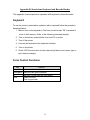
Appendix B: Stand-alone Keyboard and Barcode Reader
This appendix covers stand-alone operation with keyboard or barcode reader.
Keyboard
To use the printer in stand-alone operation with a keyboard follow the procedure
described below:
1. Make a form for the keyboard. (The form should include “ZS” command to
store to flash memory. Refer to the following command sample.)
2. Turn on the printer; download the form from PC to printer.
3. Turn off the printer.
4. Connect the keyboard to the keyboard interface.
5. Turn on the printer.
6. Check LCD for instructions of each data string/ label count/ copies; type to
input data accordingly.
Form Control Functions
Key
Function
Esc
Enter or exit from keyboard mode
Backspace Delete the last typed character
F1
Next form if more than one form exists
Enter
- Select the form
- End of typed data
76
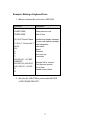
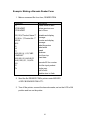
Example: Making a Keyboard Form
1. Make a command file for the form, KBD.FRM.
Command
ZS
FK"KBDFORM"
FS"KBDFORM"
Description
Enable store to flash
Delete previous one
Start of form
V00,15,N,"Product Name
?"
C0,10,N,+1,"Product No. ?"
Q50,24
q816
S2
D8
ZT
A550,20,0,4,1,1,R,"ABC
COMPANY"
B550,60,0,2,2,4,40,B,C0
A540,150,0,3,1,1,N,V00
FE
ZN
Variable and display message
Counter and display message
Label dimension
Label width
Speed
Darkness
Print from top
Fixed data
Barcode I25 for counter
Print the input product
End of form
Disable store to flash
2. Send the file, KBD.FRM to printer under MS-DOS
>COPY/B KBD.FRM LPT1:
77
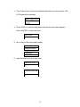
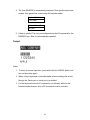
3. Turn off the printer, connect the keyboard and then turn on the printer. The
LCD displays this message:
READY (203,PPLB)
<ESC> FOR
KEYBD
4. Press <ESC> to enter the keyboard mode and the form name appears.
Press <ENTER> to select the form.
KBDFORM
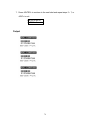
5. Key-in the product name and number.
Product Name ?
Barcode Printer
Product No. ?
0123456789
6. Input the label count and copy count.
LABEL SET NO. ?
2
COPIES PER LAB
?
3
78
7. Press <ENTER> to continue to the next label and repeat steps 5 ~ 7, or
<ESC> to exit.
ENTER to go on,
Or ESC to return
Output
79
Barcode Reader
To use the printer in stand-alone operation with a barcode reader (scanner),
follow the procedure described below
1. Make a form for barcode reader. (Note that the form name must be
“READER” The form should include “ZS” command to store to flash
memory.)
2. Turn on the printer; download the form from PC to printer.
3. Set the parameter of “READER INSTALLED” on the LCD to ON position.
4. Turn off the printer.
5. Connect the barcode reader to the keyboard interface.
6. Turn on the printer.
7. Check LCD for instructions of each data string and scan barcodes to input
data accordingly.
80
Example: Making a Barcode Reader Form
1. Make a command file for a form, READER.FRM.
Command
ZS
FK"READER"
FS"READER"
Description
Enable store to flash
Delete previous one
Start of form
V00,15,N,"Product Name ?"
C0,10,N,+1,"Product No. ?"
Q50,24
q816
S2
D8
ZT
A550,20,0,4,1,1,R,"ABC
COMPANY"
B550,60,0,2,2,4,40,B,C0
A540,150,0,3,1,1,N,V00
PA1
FE
ZN
Variable and display
message
Counter and display
message
Label dimension
Label width
Speed
Darkness
Print from top
Fixed data
Barcode I25 for counter
Print the input product
Single copy
End of form
Disable store to flash
2. Send the file READER.FRM to printer under MS-DOS
>COPY/B READER.FRM LPT1:
3. Turn off the printer, connect the barcode reader, set on the LCD to ON
position and turn on the printer.
81
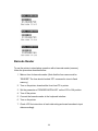
4. The form READER is automatically executed. Scan product name and
number from printed bar codes using the barcode reader.
Product No.?
11223344
Product Name?
APPLE
5. A label is printed. The copy count depends on the PA command for the
READER form. Step 4 is automatically repeated.
Output
Notes:
1. To return to normal operation, press and hold the CANCEL button and
turn on the printer again.
2. When using a keyboard or barcode reader communicating with a host
through the Centronics or serial port is prohibited.
3. For the keyboard form the P command is not allowed, while for the
barcode reader/scanner form a PA command must be included.
82
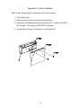
Appendix C: Cutter Installation
Refer to the following steps to install the cutter kit onto printers:
1. Turn off the printer.
2. Remove the top covers on both left and right sides.
3. Install the Cutter Baby Board to the main board JP17 socket of FM 4602
PLUS series / JP15 socket of FM 4603 PLUS series.
4. Secure the two screws for the cutter (1) and bracket (2).
83
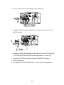
5. Loosen and remove the two screws (4) from bracket (5).
6. Insert the left side of cutter bracket (7) and secure the two screws (6) to
the TPH module.
7. Thread the cutter cable through hole (8) and route it to the JP16 connector
(CUTTER) on the FM 4602 PLUS series main boards, or to the JP14
connector (CUTTER) on the main board of FM 4603 PLUS series.
8. Turn on the printer.
9. Set parameter “CUTTER INSTALLED”, on the LCD to the ON position.
84
After the cutter is installed, install media and ribbon.
1. Put the media end on the roller.
2. Close the TPH latch.
3. Hold the PAUSE button and turn on the printer.
4. Release the button when the cutter starts cutting.
5. After cutting, the printer will feed the label for 8 inches.
Note: The procedure above is for first time installation or after cutter jam.
Normally the procedure for loading the media through the cutter is:
1. Put the media end on the roller.
2. Close the TPH latch.
3. Turn on the printer.
4. Press the FEED button to feed the media end through the cutter.
85
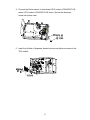
Appendix D: Dispenser Installation
Install a dispenser into the printer as follows:
1. Turn off the printer.
2. Remove the top cover on both left and right sides.
3. Assemble the related components for both left and right sides. Check
below:
86
4. Connect the Peeler sensor to main board JP15 socket of FM 4602 PLUS
series/ JP12 socket of FM 4603 PLUS series. Secure the dispenser
board onto printer case.
5. Insert the left side of dispenser bracket and secure the three screws to the
TPH module.
87
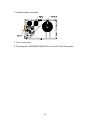
6. Install the ribbon and media.
7. Turn on the printer.
8. Set parameter “DISPENSER INSTALLED” on the LCD to the ON position.
88
Appendix E: Adjusting Ribbon Tension
The ribbon shaft has its user-friendly feature to allow users to adjust the tension
of ribbon shaft by rotating the knob. User can reset to factory default tension by
adjusting the ribbon shaft while the black line was aligned to the marked arrows.
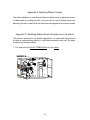
Appendix F: Switching Ribbon Wound Ink-side out or Ink-side in
The printer is produced to suit flexible applications, no matter with ribbon wound
ink-side in (manufacturing default), or with ribbon wound ink-side out. The steps
to switch are listed as follows:
1. Pull and move the SHAFT RIBBON ADJ into the Inside:
89
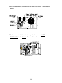
2. After the adjustment, ribbon wound ink-side in can be use. Then install the
ribbon:
3. If ribbon wound ink-side out is in use, pull and move the SHAFT
RIBBON ADJ into the Outside. Then install the ribbon:
90
91