1
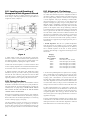
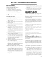
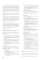
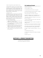
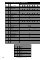
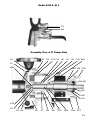
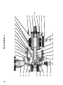
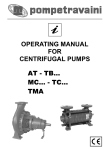
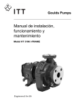
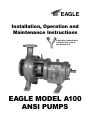
EAGLE Installation, Operation and Maintenance Instructions Lubrication information is in Section III-A, Item 1b. and Section IV-A. EAGLE MODEL A100 ANSI PUMPS TABLE OF CONTENTS SECTION I—GENERAL Introduction ................................................................................................................................................................. 3 I-A Importance of Instructions ........................................................................................................................... 3 I-B Special Warnings .......................................................................................................................................... 3 I-C Receiving Inspection—Shortages................................................................................................................. 3 I-D Preservation and Storage.............................................................................................................................. 3 I-E Handling Techniques.................................................................................................................................... 3 SECTION II—INSTALLATION II-A Location........................................................................................................................................................ 3 II-B Foundations .................................................................................................................................................. 3 II-C Leveling and Grouting of Baseplate ............................................................................................................. 4 II-D Piping Practices ............................................................................................................................................ 4 II-E Alignment—Preliminary .............................................................................................................................. 4 II-F Stuffing Box .................................................................................................................................................. 5 SECTION III—OPERATION III-A Startup .......................................................................................................................................................... 5 III-B Operation Checks......................................................................................................................................... 6 III-C Shutdown Procedure .................................................................................................................................... 6 SECTION IV—PREVENTIVE AND CORRECTIVE MAINTENANCE IV-A Lubrication ................................................................................................................................................... 6 IV-B Stuffing Box .................................................................................................................................................. 6 IV-C Vibration....................................................................................................................................................... 6 IV-D Alignment—Final......................................................................................................................................... 6 IV-E Performance.................................................................................................................................................. 6 SECTION V—DISASSEMBLY AND REASSEMBLY V-A Disassembly................................................................................................................................................... 7 V-B Inspection and Parts Replacement Guidelines............................................................................................. 7 V-C Reassembly Procedures................................................................................................................................. 7 V-D Additional Details ........................................................................................................................................ 9 SECTION VI—PRODUCT DESCRIPTION Product Description............................................................................................................. 9,10,11,12,13,14 SECTION VII—TROUBLE SHOOTING Troubleshooting .......................................................................................................................................... 15 SECTION VIII—ORDERING SPARE PARTS VIII-A Spare Parts .................................................................................................................................................. 15 VIII-B Instructions for Ordering Spare Parts......................................................................................................... 15 2 SECTION I—GENERAL Introduction This instruction manual is intended to assist those involved with the installation, operation and maintenance of Eagle Model A100 pumps. It is recommended that this manual be thoroughly reviewed prior to installing or performing any work on the pump or motor. I-A. Importance of Instructions The design, material and workmanship incorporated in the construction of Eagle pumps make them capable of giving long, trouble–free service. The life and satisfactory service of any mechanical unit, however, is enhanced and extended by periodic inspection and careful maintenance. This instruction manual was prepared to assist operators in understanding the construction and correct methods of installing, operating, and maintaining these pumps. Instruction sheets on various components as well as the Instruction Book for the pump are included in the shipment. DO NOT DISCARD! I-D. Preservation and Storage Eagle’s normal domestic shipping and storage preparation is suitable for protecting the pump during shipment in covered trucks. It also provides protection during covered storage at the jobsite, and for a short period between installation and start-up. If the pump is to be idle and exposed to the elements for an extended period, either before or after installation, special precautions are required. One approach is to provide special preservatives and wrapping before shipment. However, after installation the protective wrappings will have been removed. Therefore, application of preservatives after installation is considered a good practice. Study thoroughly Sections I, II, III, and carefully follow the instructions for installation and operation. Sections IV, V, VI, VII, and VIII are answers to trouble and maintenance questions. Keep this instruction manual handy for reference. The driver, coupling, and mechanical seal manufacturers should be contacted for their recommendations on preservation and protection procedures. I-B. Special Warnings Care should be used in moving pumps. Pumps should not be hoisted by eyebolts. These eyebolts are intended for removing the back pull–out assembly for maintenance and inspection. An assembled pump should be hoisted using a sling under suction flange and under rear of bearing frame. Bedplate mounted units should be hoisted using slings under bedplate below both pump and driver. Eagle Pump and Compressor will not be liable for any damages or delay caused by failure to comply with the provisions of this instruction manual. This pump is not to be operated at speeds, working pressures, discharge pressures, or temperatures higher than nor used with liquids other than originally intended for, without written permission of Eagle Pump. I-E. Handling Techniques I-C. Receiving Inspection—Shortages Care should be taken when unloading pumps. If shipment is not delivered in good order and in accordance with the Bill–of– Lading, note the damage or shortage on both receipt and freight bill. MAKE ANY CLAIMS TO THE TRANSPORTATION COMPANY PROMPTLY. SECTION II—INSTALLATION II-A. Location Pumping unit should be placed as close as practical to the source of supply. Floor space and headroom allotted to the unit must be sufficient for inspection and maintenance. Be sure to allow for crane or hoist service. II-B. Foundations 1. Grouted—Bedplate mounted units are normally grouted–in on a concrete foundation, which has been poured on a solid footing. This allows a permanent, vibration–absorbing base for the unit. The location and size of foundation bolts are shown on the outline assembly drawings supplied for the unit. Fig. 1 illustrates a typical foundation bolt installation. 2. Flexibly Mounted—Installation and leveling of the optional flexibly mounted bedplate should be carried out in accordance with assembly drawings supplied in the data package for the unit. WASTE LEAVE 3/4" TO11/2" UNDER BEDPLATE FOR GROUT BEDPLATE GROUT LEAVE TOP OF FOUNDATION ROUGH, AND WET BEFORE GROUTING. WEDGES DAM CONCRETE FOUNDATION Figure 1 3 II-C. Leveling and Grouting of Baseplate Initial Alignment Check 1. Put the unit in place on wedges located at four points as shown in Fig. 2. Some long installations may require additional wedges near center of bedplate. WEDGES Figure 2 2. Adjust wedges to level unit (approximately), placing unit between 3⁄4” and 11⁄2” above foundation. Level or plumb suction and discharge flanges. Then, bring the coupling halves into reasonable alignment by adjusting the wedges as needed. 3. Make sure that the baseplate is not distorted and that final accurate coupling alignment can be established within the limits of movement of motor and by shimming motor if necessary. 4. Tighten foundation bolts finger tight. Build dam around foundation and pour grout. Fill to level of grout hole making sure that the areas under the pump and motor feet are filled solid. Allow grout to harden at least 48 hours before further tightening foundation bolts. Tighten pump hold down bolts. II-D. Piping Practices Guidelines for piping are given in the “Hydraulic Institute Standards” and should be reviewed prior to pump installation. All piping should be supported independently of, and line up naturally with, the pump flanges. NEVER DRAW PIPING INTO PLACE BY USE OF FORCE AT THE FLANGED CONNECTIONS OF THE PUMP. Both suction and discharge piping should be as short and direct as possible to minimize friction losses. Foundation, pump and driver hold–down bolts should be tightened prior to connecting suction or discharge piping to the pump. On units handling corrosives, the piping can be arranged to allow flushing of the pump prior to opening of the unit for servicing. After connecting suction and discharge piping to the pump, rotate pump by hand to be sure that there is no binding. 4 II-E. Alignment—Preliminary Alignment of the pump and driver is of extreme importance for trouble–free mechanical operation. Alignment should be obtained by adding or removing shims from under the motor feet. The pump bearing frame foot should never be adjusted to obtain alignment. The proper shimming is installed under the bearing frame foot at the factory on units shipped with bedplates. Changing the pump casing or bearing frame in the field will require a reshimming of the frame foot. The proper number of shims is installed when the pump shaft is level and parallel to the bedplate surface. Proper shimming is achieved by loosening frame foot and tightening casing foot. This should create a gap between the frame foot and bedplate between 0 and .040 inches (1mm). This must be filled with shims and the frame foot retightened. If this procedure is not followed, mechanical problems can result. The final alignment is done after the unit has been run under actual operating conditions. The following are suggested steps for aligning the unit, prior to initial startup. 1. Parallel Alignment: The unit is in parallel misalignment when the shaft axes are parallel, but not concentric. During initial alignment, vertical parallel alignment may be different, due to thermal expansion of the unit at actual operating conditions. The following is a suggested cold setting for motor driven units: Pumpage Temperature Above Ambient Ambient 100° F. 200° F. 300° F. 400° F. 500° F. Set Motor Shaft .002–.004” low (.05–.10 mm) .000–.002” high (.00–.05 mm) .004–.006” high (.10–.15 mm) .008–.010” high (.20–.25 mm) .012–.014” high (.30–.35 mm) .016–.018” high (.40–.45 mm) 2. To check the parallel alignment of “spider–insert” couplings, place a straight edge across both hubs at four points, 90° apart (see Fig. 3). To check the parallel alignment of flexible spacer couplings, place a dial indicator on one hub and rotate that hub 360° while taking readings on the outside diameter of the other hub. Alignment occurs when indicator deflection does not exceed .002” T.l.R. (see Fig. 4) of the recommended cold setting in elevation and not more than .002” T.l.R. side to side. To check angular alignment of a “spider–insert” coupling, use calipers at 90° intervals on the circumference on the outer end of hubs. When caliper measurements are identical, the unit is in angular alignment. The correct gap between the hub and insert will be given in the coupling manufacturer’s instructions supplied for the pump. To check angular alignment of flexible spacer couplings, place a dial indicator on one shaft hub and rotate the hub 360°. Take readings from the face of the other hub. Alignment is achieved when deflection does not exceed .002” (see Fig. 5). PRIOR TO COUPLING DRIVER TO PUMP, ROTATION OF DRIVER SHOULD BE CHECKED! Serious damage can result if pump is rotated in wrong direction. Once motor rotation is checked, connect coupling, following the manufacturer’s instructions. If a coupling guard is furnished with the unit, ensure that it is securely fastened in place. WEDGES Figure 5 Figure 3 II-F. Stufng Box 1. Packing: If the pumpage is dirty or hot, it is not suitable to lubricate the packing. An external source must be utilized, unless the bypass is equipped with proper separator, filter, and/or cooling system. This must be piped into the lantern ring connection, also (refer to packing recommendations). Figure 4 R O TAT E THIS HUB 2. Mechanical Seals: When mechanical seals are supplied, they are installed and adjusted at the factory. They must not run dry or in abrasives. Connect recirculation, flush and/or cooling lines as required, following instructions on the seal print supplied for the unit. Figure 4 SECTION III—OPERATION III-A. Startup 1. Check List a. Lubrication—Pump bearings are normally oil lubricated. (THE BEARINGS ARE NOT LUBRICATED AT THE FACTORY.) These pumps are supplied with an oiler which maintains a constant oil level in the bearing frame. Locate oiler as shown on the outline drawings supplied for the unit. See Fig. 6 for correct adjustment of oiler. SET SCREW OIL LEVEL OIL LEVEL Figure 6 5 b. c. d. A high quality turbine type oil with rust and oxidation inhibitors should be used. Under normal operating conditions, an oil of 300 SSU viscosity at 100° F. (approximately SAE 20) should be used. Fill oiler bottle and replace in oiler housing. Repeat until oil remains visible in bottle. Do not add oil through the vent or breather. Optional grease lubricated bearings are lubricated at the factory and need lubrication only after 2,000 hours of operation, or every 3 months, which ever occurs first. On pumps supplied with greased–for–life bearings, no additional lubrication is required for the life of the bearing. Oil Mist lubrication of bearings is available on A100–X frames. This can be supplied at time of order, or field conversion can be done. Refer to the instructions of the manufacturer of the Oil Mist System. Priming—Pump and suction piping must be full of liquid before pump is started. Usually suction supply will be primed when shutoff valves are opened, if pump is below suction supply. If suction supply is below pump, priming by other means, such as a foot valve or ejector, will be required. Free Rotation—Rotate shaft by hand to make sure it is free. Drag from packing or seal is normal but, if pump cannot be rotated by hand or binding or rubbing is noticed, correct before starting pump. 2. Startup a. Valves—Be sure suction valve is fully open. Normally, discharge valve should be at least partially closed for flow control. b. Rotation Check—if not already done, uncouple the unit and jog the motor to check for proper rotation (refer to Section II–E–2, page 5). III-B. Operation Checks Inspect pump carefully and frequently during the first few hours of operation. If packing runs hot, shut pump down, allow box to cool, loosen gland if necessary. (Do not loosen gland until packing has cooled.) Mechanical seal may weep slightly, but should “run–in” in a few hours. Be sure all auxiliary lines (cooling, flushing, sealing, etc.) are functioning properly. Check pump bearings for excessive heating. Bearing housing operating temperatures vary depending on a wide variety of conditions. However, normal temperatures should be 120° to 180° F. (49° to 82° C). A change of temperature can indicate a problem, and operating temperatures outside of the normal range should be addressed with manufacturer. Check complete unit for excessive vibration and unusual noises. Do not run pump at greatly reduced flow because damage can result. III-C. Shutdown Procedure Back flow through pump will cause reverse rotation. If backflow is excessive, and there is a possibility of the pump being turned on during this period of reverse rotation, then precautions should be taken to prevent the backflow. This can be done by installing a check valve in the discharge line, or by closing a discharge valve immediately prior to shutting down the pump. NOTE: IT IS NOT RECOMMENDED THAT THE PUMP RUN LONGER THAN ABSOLUTELY NECESSARY AGAINST A CLOSED DISCHARGE VALVE. SECTION IV—PREVENTIVE AND CORRECTIVE MAINTENANCE IV-A. Lubrication Oil lubricated units require that oil be visible in the reservoir at all times. Oil should be changed every 4000 hours of operation. Grease lubricated units should be regressed every 2000 hours or 3 month intervals, whichever occurs first. Use a sodium or lithium grease and fill until grease comes out grease relief fittings. Follow motor and coupling manufacturers’ lubrication instructions. IV-B. Stufng Box 1. Packing Stuffing Box: Periodically inspect stuffing box to see that there is sufficient leakage to lubricate the packing and maintain a cool box. Never restrict the leakage from the packing as this will cause damage to both packing and shaft sleeve. Draw up gland nuts slowly and evenly and only while pump is running. After pump has been in operation for some time and the packing has been completely “run–in”, a leakage of 40 to 60 drops per minute of the liquid should be allowed to flow from the stuffing box at all times for cooling and lubricating the packing and shaft sleeve. 6 2. Stuffing Boxes with Mechanical Seal: Although this type of box requires no attention, a periodic inspection of the circulating lines will ensure that they do not become clogged. IV-C. Vibration It is good practice to periodically monitor vibration of the pump. Normally, the vibration level will be well within accepted standards. Of equal importance is that the vibration level not increase. If a problem with vibration is encountered, refer to Trouble Shooting, Section VII. IV-D. Alignment—Final Alignment should be checked after unit has reached operating temperature, following startup. Repeat alignment procedures outlined in Section II–E. Check alignment again after one week of operation. IV-E. Performance If performance deteriorates, refer to Trouble Shooting, Section VII. SECTION V—DISASSEMBLY AND REASSEMBLY V-A. Disassembly o. (refer to Sectional Views in Part VI) 1. Prepare pump for disassembly as follows: a. Lock out power supply to motor. b. Shut off valves controlling flow to and from pump. c. Flush pump of all corrosive or toxic liquid, if required. d. Remove all auxiliary tubing and piping. e. Disconnect coupling and remove coupling spacer. f. Drain oil. g. On units with packed stuffing box, unbolt packing gland (107). 2. Disassemble pump as follows: a. Place sling from hoist through eyebolt (132). On S units, place sling through frame (228A) above shaft (122). b. Remove frame foot hold down bolts. c. Remove bolts (370) holding frame (228A) or frame adapter (108) to casing (100). d. Slide back pull–out assembly from casing, using jacking bolts (418) provided. e. Remove casing gasket (351). f. Unscrew impeller (101) from shaft (122). The threads are right hand. Remove O–ring (412A) which seals between the impeller and shaft or sleeve. g. (1) On units with inside mechanical seal, remove gland stud nuts (355) and carefully slide gland toward bearing frame (228A). (2) On units with outside mechanical seal, loosen set screws holding rotary portion of seal to shaft and slide seal toward bearing frame. Remove gland stud nuts and carefully slide gland off studs. h. Remove stud nuts (370H) which hold stuffing box cover (184) to frame adapter. Pull stuffing box cover from frame or adapter. Slide sleeve (if any) off shaft. i. On units with mechanical seal, loosen set screws holding rotary portion of seal to shaft, and carefully slide seal and gland assembly off shaft. On units having a shaft sleeve, it is not necessary to remove rotary portion of seal from sleeve unless replacement of seal is required. j. Slide deflector (123) off shaft. k. Scribe shaft at coupling hub for proper positioning of hub during reassembly and remove hub. l. Remove bearing housing bolts (370C). Using impeller adjustment bolts (370D) for jacking, remove shaft and bearing assembly from frame. This will include the shaft, both bearings (112A) and (168A), and bearing housing (134A). Do not lose or damage O–ring (496). m. Remove inboard bearing (168A) using a bearing puller. Never use a hammer to drive shaft through bearing! Protect bearing from contamination. n. Scribe bearing housing for proper positioning prior to disassembly on S, M and L models, remove bearing housing retaining ring (361A) and slide bearing housing off ball bearing. Do not damage oil seal (332A). On X units, remove bearing end cover bolts (109A) and slide cover off shaft. Do not damage oil seal (332A). Slide bearing housing off shaft. p. Straighten tang in lock washer and remove bearing locknut (136) and lock washer (382). Remove ball bearing (112A) using a bearing puller. Protect bearing from contamination. On units with stuffing boxes, remove lantern ring (105) and packing rings (106) from stuffing box cover (184). V-B. Inspection and Parts Replacement Guidelines 1. Impeller—Replace if impeller shows excessive erosion, corrosion, extreme wear, or vane breakage. O–ring groove and impeller hub must be in good condition. Check impeller balance if possible. Reduction in hydraulic performance and reduced mechanical seal, packing or thrust bearing life may be caused by excessive impeller wear. 2. Shaft—Check for runout (.005” max) to see that shaft has not been bent. On pumps without shaft sleeves, shaft surface in stuffing box area must be smooth and free of grooves. Bearing seats and oil seal area must be smooth and free of scratches or grooves. Shaft threads must be in good condition. Metalize or replace shaft if necessary. 3. Shaft Sleeve—Sleeve surface in stuffing box must be smooth. If grooved, replace or metalize. 4. Mechanical Seal—Seal faces, gaskets, and shaft sealing members must be in perfect condition or leakage may result. Replace worn or damaged parts. 5. Ball Bearings—Replace if worn, loose or rough and noisy when rotated. 6. Oil Seals—Replace if worn or otherwise damaged. 7. General—All parts should be clean before assembly. All burrs should be removed. V-C. Reassembly Procedures This procedure covers reassembly of pump after complete disassembly. Make sure all directions outlined in Section V–B have been followed. 1. Oil shaft at thrust bearing fit on coupling end of shaft (122A). Slide thrust (coupling end) bearing (112A) on shaft as far as possible by hand. Place pipe or driving sleeve over shaft, making sure it rests against inner face only. Make sure bearing is “square” on shaft. Tap or press evenly until bearing is seated firmly against shaft shoulder. Do not mar the shaft. 2. Place lockwasher and bearing locknut (136) on shaft and tighten firmly. Bend “tang” of lockwasher into slot in locknut. 3a. On S, M and L models. Take care not to damage oil seal (332A), slide the bearing housing (134A) with O–ring (496) in place over drive end of the shaft, and in place over the bearing. b. On X models. Slide bearing housing (134A) with O–ring over impeller end of the shaft, and in place ove the bearing. Install O–ring (496A) on bearing end cover (109A) and slide into bearing housing (134A) and tighten into place with fasteners and ensure that there is no remaining end float in bearing outer race and that bearing operates smoothly. 7 4. On S, M and L models, insert retaining ring (361A) into groove in bearing housing (134A). Flat side of retaining ring must be against bearing (112A). On X units, slide bearing end cover (109A) and gasket (360C) on shaft. Ensure the “top” of end cover (109A) lines up with the “top” of bearing housing (134A), check scribe marks. If the bearing housing (134A) is not installed properly (oil drain groove in bottom), oil will not be able to drain from bearing causing it to overheat and fail prematurely. 5. Oil inboard bearing seat on shaft. Slide inboard ball bearing (168A) on shaft (122) as far as possible by hand. Continue as in Step 1 above. 6. Place a small amount of O–ring lubricant on inside of bearing frame (228A) at bearing housing (134A), at inboard bearing seats (168A), on O-ring (496), and on inboard oil seal (333A). Carefully slide shaft assembly into bearing frame. Do not damage inboard oil seal (333A). Screw bearing housing bolts (370C) about 1⁄2” into bearing frame (228A) . 7. Slide deflector (123) on shaft (122). 8. If unit has packed stuffing box, place stuffing box cover (184) against adapter (108), making sure that studs (370H) align with proper holes in adapter. Replace nuts and firmly tighten. Slide sleeve (if any) on shaft. Make sure grooves in end of sleeve engage drive pin on shaft. Continue assembly at Step 10. 9. If unit has mechanical seal: The following instructions refer to pumps equipped with mechanical seals, either with or without sleeves. If the unit has a single inside or double seal, a preliminary impeller adjustment must be performed to assure proper positioning of mechanical seal. (1) Position sleeve (126), if any, on shaft (122) and engage groove in sleeve with drive pin (469) on shaft. Place stuffing box cover (184) against frame (228). Make sure studs (370H) align with proper holes in frame. Firmly tighten nuts or bolts. (2) Screw impeller (101) with O-ring (412A) in place on shaft. Make sure that shaft assembly extends through stuffing box cover (184) so that the impeller will NOT contact face of stuffing box cover. (3) Using impeller adjusting bolts (370C and 370D), adjust the impeller end clearance 0.015 with volute in place. Mark shaft sleeve. The following instructions are for three basic seal types: Single Inside, Single Outside, and Double Seals. Refer to seal manufacturer’s drawing seal type and positioning dimension. Follow pertinent procedures. a. Single Inside Seal (1) Scribe the shaft (122) or shaft sleeve (126) lightly at the face of the stuffing box. (2) Remove the impeller and stuffing box. (3) Assemble the gland (250) with gaskets and stationary seat and slide the assembly over the shaft (122) or shaft sleeve (126). (4) Slide the rotary portion of the seal on the shaft (122) (or shaft sleeve) (126) establishing its location from the scribe line to the dimension as shown on the seal manufacturer’s drawing. Tighten set screws. (5) Reinstall the stuffing box cover and tighten. Do not damage the seal parts. (6) Reinstall the impeller with O-ring. (7) Slide the gland assembly against the stuffing box and tighten the nuts evenly. Do not damage the seal parts. (8) Refer to Step 12 for further assembly details. b. Double Seals (1) Scribe the shaft (122) or shaft sleeve (126) lightly at the face of the stuffing box. (2) Remove the impeller and stuffing box. (3) Assemble the gland (250) with gaskets and stationary seat and slide the assembly over the shaft (122) or shaft sleeve (126). (4) Slide the rotary portion of the seal on the shaft (122) or shaft sleeve (126) establishing its location from the scribe line to the dimension as shown on the seal manufacturer’s drawings. Tighten set screws. (5) Place inboard stationary seat and gaskets into bottom of stuffing box. (6) Reinstall the stuffing box cover and tighten. Do not damage seal parts. (7) Reinstall the impeller with O–ring. (8) Slide the gland assembly against the stuffing box and tighten the nuts evenly. Do not damage seal parts. (9) Refer to Step 12 for further assembly details. c. Single Outside Seal Preliminary impeller adjustment is not necessary with this type of mechanical seal. (1) If unit has shaft sleeve (126), slide on shaft (122) and engage groove in sleeve with drive pin (469) on shaft. (2) Lubricate rotary portion of seal and slide on shaft sleeve. Do not tighten set screws. (3) Assemble gland (250), gaskets, and stationary seat and slide assembly on shaft or sleeve. (4) Place stuffing box cover (184) against frame making sure that the studs (370H) align with the proper holes in frame. Firmly tighten nuts. (5) Screw impeller with O–ring on shaft making sure impeller does not make contact with stuffing box cover. If the impeller does hit, use impeller adjusting cap screws to correct. (6) Place gland assembly against face of stuffing box and firmly tighten stud nuts. (7) Slide rotary portion toward gland until it contacts stationary seat. Compress the rotary. Tighten screws. 10. Screw impeller (101) with O–ring (412A) in place, on the shaft (122). 11. On units with stuffing box packing (106), repack stuffing box as outlined in Section II–F. Assemble gland stud nuts finger tight. 12. Install and position coupling hub at scribe mark on shaft. 8 13. Place casing gasket (351) against shoulder in casing. 14. Slide the pullout assembly into the casing (100). Drain slot in stuffing box cover (184) should line up with drain connection in casing. Install frame–to–casing bolts (370) and tighten evenly while rotating shaft (122) by hand. If impeller ceases to turn freely, stop tightening operation and adjust the impeller setting with the adjusting bolts (370C and 370D) before resuming tightening of frame-to-casing bolts (370). 15. Impeller Clearance The impeller clearance is an important factor in maintaining optimum pump performance. The nominal clearance is .015” with the recommended minimum being .008”. The actual clearance setting is dependent on the specific operating conditions, taking into account temperature, solids, etc. For maximum service flexibility pumps are shipped from the factory with the clearance set at .015”. The desired clearance is obtained in the following manner: a. Loosen bolts (370C and 370D). b. Tighten bolts (370C) with turning shaft clockwise until impeller starts to rub against casing. c. Loosen bolts (370C) until a feeler gauge, corresponding to the desired clearance, can be placed between the bolt head and bearing housing. d. Tighten bolts (370D) evenly. Bearing housing shaft and impeller will be jacked to proper clearance from casing. Tighten bolts (370C) and jam nuts on bolts (370D). e. If desired, a dial indicator can be used instead of a feeler gauge to check that the bearing housing has been moved the correct distance. V-D. Additional Details An alternate method for setting inside mechanical seals is the “Modified Visegrip Method”. 1. Follow assembly up to Step 7. 2. Assemble the gland with stationary seat and gaskets. 3. Install the shaft sleeve, if used on the shaft, and engage groove in sleeve with drive pin (469) on shaft. 4. Slide gland assembly over the shaft or shaft sleeve. 5. Install the stuffing box cover and impeller. Establish a preliminary rotor adjustment (refer to Section V–C–9). 6. Slide gland assembly against stuffing box. Do not bolt the gland to the stuffing box. 7. Clamp the modified visegrip on the shaft or sleeve directly behind and against the gland. 8. Leave the visegrip in place and remove the impeller and stuffing box cover. 9. Lubricate the rotary portion of seal and slide it on the shaft until it comes in contact with the stationary seat in the gland. 10. Compress rotary portion of seal to correct dimension as shown on seal manufacturer’s drawing. Tighten set screws. 11. Remove visegrip and reinstall stuffing box cover and tighten. 12. Reinstall impeller with O–ring. 13. Slide the gland assembly against the stuffing box and tighten nuts evenly. 14. Refer to Step 12, etc. SECTION VI—PRODUCT DESCRIPTION See pages 10, 11,12, 13 and 14 for Sectional Views, Parts List and Materials of Construction. 9 Parts List and Materials of Construction All Carbon Steel CS CS No. Reqd. Item No. Per Pump Part Name Casing 100 1 1 Impeller 101 1 Lantern Ring 105 1 Set Stuffing Box Packing 106 1 Gland (Packed Box) CS 107 1 Frame Adaptor 108 1 Bearing End Cover 109A 1 Ball Bearing-Outboard 112A 1 Bearing Frame Breather 113A 1 Pump Shaft (Less Sleeve) 122* 4340 1 Pump Shaft (With Sleeve) 122A 1 Deflector 123 1 Shaft Sleeve 126 316 1 Casing Foot 131 1 Eye Bolt 132 1 Bearing Housing 134A 1 Bearing Locknut 136 1 Ball Bearing-Inboard 168A 1 CS Stuffing Box Cover-Standard 184 CS 1 Stuffing Box Cover-Jacketed 184A 1 Mechanical Seal Guard 210 1 Bearing Frame 228A Drain Plug CS 1 239 1 Bearing Frame Foot 241 1 Constant Level Oiler (Not Illustrated) 251 1 Mechanical Seal Gland Gasket 261 1 Oil Seal-Outboard 332A 1 Oil Seal-Inboard 333A 1 Gasket-Casing 351 2 Gland Stud 353 4 Gland Stud Nut 355 1 Gasket-Brg Frame-Adaptor 360D 1 Retaining Ring-Bearing Housing 361A Cap Screw-Frame Adapt. to Casing 4-24 Steel 370 3-4 Cap Screw-Bearing Housing 370C 3-4 Cap Screw-w/Jam Nut-Impeller Adjust. 370D 2 Cap Screw-Casing Foot 370E Cap Screw-Frame Foot 1-2 370F Stud & Nut-Cover to Adaptor 2 370H Cap Screw-End Cover to Brg. Housing 6 371C Bearing Lockwasher 1 382 “O” Ring-Impeller 1 412A Cap Screw-Jacking (not shown) 2-3 418 Dowel Pin-Frame to Adaptor 469B 2 Drive Pin-Shaft Sleeve 469D 1 “O” Ring-Bearing Housing 496 1 “O” Ring-Bearing End Cover 496A 1 Adaptor Ring 503 1 *Available in Hast-B or Hast-C Material. NOTES: 1Not available on all sizes. All 316SS 316 316 All CD4MCu CD4M CD4M 316 CD4M 316 4340 CD4M 316 316 CD4M CD4M 316 CD4M 304 304 MATERIAL All All Monel C-20 C-20 Monel C-20 Monel Stainless Steel Teflon C-20 Monel Cast Iron Cast Iron Steel Stainless Steel C-20 Monel Stainless Steel C-20 Monel Cast Iron Steel Cast Iron Steel Steel C-20 Monel C-20 Monel 316 Cast Iron C-20 Monel Cast Iron Aluminum Alloy/Plastic Manila Paper Buna Rubber Buna Rubber Non-Asbestos (C4400) Vellumoid Steel 304 Steel Steel Steel Steel 304 Steel Steel Teflon 304 Steel 420 Buna Rubber Buna Rubber Cast Iron Recommended Spare Parts 101 106 112A 126 168A 261 332A 333A 351 360C 360D 412A 469D 496 NOTES: 10 1 1 set 1 1 1 1 1 1 1 1 1 1 1 1 Impeller Stuffing Box Packing Ball Bearing-Outboard. Shaft Sleeve Ball Bearing-Inboard (2) Mechanical Seal Gland Gasket Oil Seal-Outboard Oil Seal-Inboard (3) Gasket-Casing Gasket-Bearing End Cover-Bearing Housing Gasket-Bearing Frame-Adaptor (not shown) (4) “O” Ring-Impeller Drive Pin-Shaft Sleeve “O” Ring Bearing Housing Mechanical Seal (3) (2) - Required on packed pumps only. (3) - Required on pumps equipped with mechanical seal only. (4) - For M & L pumps only. All Nickel Nickel Nickel *All Hast. Hast. Hast. All Titanium Titanium Titanium Nickel Hast. Titanium Hast. Titanium Nickel Hast. Titanium Nickel Nickel Hast. Hast. Titanium Titanium Nickel Hast. Titanium Nickel 1 316 Monel Monel Model A100 S, M, L 370 503 Assembly View of 8” Pumps Only 100 370 184 370H 126 261 210 123 113A 168A 101 469D 361A 496 370D 136 & 382 332A 134A 112A 412A 106 105 239 351 107 353 355 122A 333A 228A 370C 11 12 131 239 105 469D 412A 106 101 351 100 370E 370H 126 122A 210 333A 106 370F 228A 370C 361A 134A 136 & 382 332A 112A 370D 370 184 108 132 107 355 360D 353 123 168A 113A 496 Model A100 M, L 13 239 370H 105 106 469D 412A 101 184 351 100 131 370E 370 107 132 355 108 353 126 469B 333A 360D 261 Model A100 X 106 210 228A 370D 371C 109A 332A 136 & 382 496A 134A 112A 496 168A 113A 122A 370F 123 SECTION VII—TROUBLE SHOOTING Problem Possible Causes & Corrections A. No liquid delivered, not enough liquid delivered, or not enough pressure 1, 2, 3 ,4, 5, 6, 7, 8, 9, 10 11, 12, 13, 14, 18, 19, 20. B. Pump works a while and then quits 4, 5, 7, 8, 9, 11, 12, 20. 11. Foot valve or suction pipe not immersed deep enough— consult factory for proper depth. Use baffle to eliminate vortices. 12. Entrained air or gases in liquid—consult factory. 13. Impeller clearance too great—check for proper clearance. 14. Impeller damaged—inspect and replace as required. C. Pump takes too much 6, 13, 14, 15, 16, 21, power 22, 23, 24, 31. D. Pump is noisy or vibrates 10. Foot valve too small—install correct size foot valve. 15, 16, 17, 28, 31. E. Pump leaks 8, 24, 25, 26, 27. excessively at stuffing box 15. Rotating parts bind—check internal wearing parts for proper clearances. 16. Shaft bent—straighten or replace as required. 17. Coupling or pump and driver misaligned—check alignment and realign if required. F. High bearing temperature 15, 16, 17, 29, 30, 31. 18. Impeller diameter too small—consult factory for proper impeller diameter. G. Stuffing box overheating 8, 24, 25, 26, 27. 19. Improper pressure gauge location—check correct position and discharge nozzle or pipe. Causes & Corrective Measures 1. Pump not primed or properly vented—check that casing and suction pipe are completely filled with liquid. 2. Speed too low—check whether motor wiring is correct and receives full voltage or turbine receives full steam pressure. 3. System discharge head too high—check system head (particularly friction losses). 4. Suction lift too high—check NPSH available (suction piping too small or long may cause excessive friction losses). Check with vacuum or compound gauge. 5. Impeller or piping obstructed—check for obstructions. 6. Wrong direction of rotation—check rotation. 7. Air pocket or leak in suction line—check suction piping for air pockets and/or air leaks. 8. Stuffing box packing or seal worn allowing leakage of air into pump casing—check packing or seal and replace as required. Check for proper lubrication. 9. Not enough suction head for hot or volatile liquids—increase suction head, consult factory. 14 20. Casing gasket damaged—check gaskets and replace as required. 21. Speed too high—check motor winding voltage or steam pressure received by turbine. 22. Head lower than rating; pumps too much liquid—consult factory. Install throttle valve, cut impeller. 23. Liquid heavier than anticipated—check specific gravity and viscosity. 24. Stuffing box not properly packed (insufficient packing, not properly inserted or run in, packing too tight)—check packing and repack stuffing box. 25. Incorrect packing or mechanical seal—consult factory. 26. Damaged mechanical seal—inspect and replace as required. Consult factory. 27. Shaft sleeve scored—remachine or replace as required. 28. Cavitation—increase NPSH available. Consult factory. 29. Pump capacity too low—consult factory for minimum continuous flow. 30. Excessive vibration—See Section D. 31. Improper bearing lubrication or bearings worn out—inspect and replace as required. SECTION VIII—ORDERING SPARE PARTS VIII-A. Spare Parts To insure against possible long and costly downtime periods, especially on critical services, it is advisable to have spare parts on hand. VIII-B. Instructions for Ordering Spare Parts Repair orders will be handled with the minimum of delay if the following directions are followed: 1. For critical services: It is recommended that a “back pull–out assembly” be kept on hand. This is a group of assembled parts which includes all parts except the casing and the coupling. 1. Give model number, size of pump, and serial number. These can be obtained from the nameplate on the pump. If this unit is equipped with stuffing box packing, one set of stuffing box packing (item 106) should be on hand. 2. Write plainly the name, part number, and material of each part required. These names and numbers should agree with those on the sectional drawing in Section VI. 2. An alternative, though not as desirable as that stated above, can be used on non–critical services. This involves having on hand parts that are most likely to wear and can be used as needed. See Section VI, Parts List, for these recommended spares. 3. Give the number (quantity) of parts required. 4. Give complete shipping instructions. 15 EAGLE EAGLE PUMP & COMPRESSOR LTD. 7025 - 5 Street S.E., Calgary, AB T2H 2G2 Canada ANSI Centrifugal Pumps Multistage Horizontal Pumps Vertical Sump Pumps Rotary Screw Compressor Air/Gas Dryers www.eagle-pc.com 01/2000 Printed in Canada