1
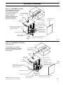
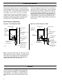
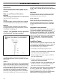
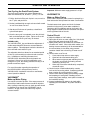
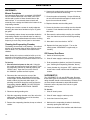
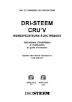
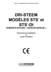
READ AND SAVE THESE INSTRUCTIONS
®
VAPORMIST and
VAPORMIST DI
®
ELECTRIC STEAM HUMIDIFIERS
For Ducted or Ductless Applications
Installation Instructions
and
Maintenance Operations
Manual
UL LISTED
CUL LISTED
ä
TABLE OF CONTENTS
TO THE PURCHASER AND INSTALLER
Thank you for purchasing our VAPORMIST® humidifier. We have designed and built this equipment to give you
complete satisfaction and trouble-free service for many years. Familiarizing yourself with this manual will help you
to ensure proper operation of the equipment for years to come.
This manual covers the installation and maintenance procedures for both the VAPORMIST AND VAPORMIST DI
humidifiers.
DRI-STEEM Humidifier Company
VAPORMIST Diagrams ........................................ 3
Installation
Locating and Mounting the VAPORMIST
Humidifier .............................................................
Examples of Mounting the Dispersion Tube............
Mounting Dispersion Tube with Condensate
Drain Line .............................................................
Connecting Dispersion Tube and Humidifier ...........
4
4
5
5
Piping and Wiring ............................................... 6
Electrical Specifications and
Capacities/Dimensions ....................................... 7
Area-Type Application Using Space
Distribution Unit (SDU) ....................................... 8-9
Start-up and Operation ....................................... 10-11
Maintenance Procedure ...................................... 12-13
VAPORMIST Trouble-Shooting Guide ................ 14
VAPORMIST DI Trouble-Shooting Guide ............ 15
Replacement Parts .............................................. 16-20
Maintenance Service Record .............................. 21
Two-Year Limited Warranty ................................. 22
2
VAPORMIST® DIAGRAMS
Figure 3-1: VAPORMIST Humidifier
The VAPORMIST unit requires
water conductivity of at least
100 micromhos/centimeter
1-½" or 2" Flexible vapor
(2 grains per gallon) to
hose connects to dispersion
tube induct.
operate. It will not
operate with water treated
Vapor Hose
by reverse osmosis or
Connector
deionization processes.
Duct
Removable Front Panel
with Key Lock
Condensate
Return Line
Wall Mounting
Bracket
Vapor Hose Connection
Water Inlet Stand Pipe
¾" flexible hose connection
to skimmer port and
overflow drain.
Entire floor of unit is a drip tray. Tray has
threaded drain fitting for piping to
plumbing drain in building.
Evaporating chamber
drain connected by ¾"
flexible hose to timeroperated dump valve.
T-handled Utility Knobs
INCOLOY Alloy-Sheathed
Immersion Heaters
Removable
Evaporating
Chamber
Slide assembly under evaporating chamber
provides easy removal for cleaning
OM-287
Figure 3-2: VAPORMIST DI Humidifier
(Deionized Water)
The VAPORMIST DI humidifier
shown here is specifically designed
for use with deionized or reverse
osmosis water.
1-½" or 2" Flexible vapor
hose connects to
dispersion tube induct.
Duct
Vapor Hose
Connector
Wall Mounting
Bracket
Vapor Hose Connection
¾" Flexible hose connection
to overflow drain.
T-handled
Utility Knobs
Evaporating chamber drain
connected by ¾" flexible
hose to ball valve.
Entire floor of unit is a drip tray. Tray has
threaded drain fitting for piping to
plumbing drain in building.
Front
Panel with
Key Lock
Water Float Valve
Removable
Evaporating
Chamber
Slide assembly under evaporating chamber
INCOLOY Alloy-Sheathed
provides easy removal for cleaning
Immersion Heaters
Low Water Cut Off Switch*
*Caution: Low-Water Cut-Off Switch contact is
normally open when float is in its lowest position.
OM-288
3
INSTALLATION
Locating and Mounting the VAPORMIST®
Humidifier
The VAPORMIST humidifier is designed to hang on a
wall, and should be installed in a mechanical room or in
a space located near an air duct system.
Consider the following when selecting the location of the
humidifier:
• Visible location (preferred)
• Convenient access to duct
• Electrical and plumbing connections
• Required clearances
The mounting location should provide a minimum
clearance of 36" to the front and 24" to the right side of
the unit. This clearance is required for removing the
evaporating chamber and accessing electrical compartment.
Electrical power supply, water make-up piping and drain
piping must also be considered. These service connections are made at the lower right rear corner of the unit.
When mounting on a stud wall (studs 16" on center),
locate studs and position mounting bracket in place so
that each of the two holes (16" apart) will center on a
stud. Mark hole locations and pre-drill 1/4" diameter
pilot holes. Secure bracket to wall with lag bolts provided.
For hollow block or poured concrete wall mounting,
position mounting bracket in place and mark the second
hole from each end. Drill appropriate pilot hole for two
3/8" toggle bolts or two 3/8" machine bolt lead anchors.
Secure bracket in place.
When the VAPORMIST humidifier is in final operation,
the panel access keys should be removed and secured
in a different place.
Examples of Mounting the Dispersion Tube
Figure 4-1: Mounted Horizontally in Duct
Figure 4-3: Mounted Vertically (Optional)
1½” Vapor
Hose
OM-228
Vapor hose and dispersion tube should be pitched back to the
humidifier with a gradual slope of 2" per foot (minimum).
Figure 4-2: Mounted Horizontally in Duct and Lower
Than VAPORMIST Unit
OM-230
This is not recommended on VM16, VM25, and VM34.
When duct is located more than 10 feet away from unit, vapor hose is
not recommended; 1½” minimum I.D. hard pipe should be used instead.
6" min.
Tee
3" to 5" (6" to 12" for
VM25 and VM34)
OM-229
A water seal must be located in drain line as shown to maintain steam
pressure.
4
INSTALLATION
VAPORMIST® Mounting Tube
with Condensate Drain Line
• Mount dispersion tube level.
• For best vapor absorption, orient
dispersion tube so that tubelets are
directed against the air flow.
Figure 5-1: Single Tube
Insertion Length
2.5"
Connecting Dispersion Tube to
Humidifier
• Connection can be made with vapor
hose or rigid tubing
• Vapor piping should have a
minimum I.D. of 1½".
• A minimum pitch of 2" per foot
back to the humidifier should be
maintained.
• 90° elbows are not recommended;
use two 45° elbows 12" apart
instead.
• Thin-walled tubing will heat up faster
than heavy-walled pipe, causing less
steam loss at start-up.
• Insulating rigid tubing will reduce
the steam output loss caused by
condensation.
• When mounting the humidifier
above the level of dispersion tube,
see figure 4-2 on page 4.
Failing to follow these recommendations
may result in excessive back pressures
being imposed on the humidifier. This
may lead to dispersion tube(s) spitting,
lost water seals, or leaking gaskets.
When distances between humidifier and
the dispersion tube(s) exceed 20 feet,
consult factory for recommendations.
Pre-molded High
Temperature Resin Tubelets
3.25"
3.25"
3.25"
½" O.D. Type 304
Stainless Steel
Tubing (condensate
drain)
3.25"
¼" NPT***
Movable Escutcheon
Plate (Plate can be mounted
within limits of 2.5".)
3/8" - 16
Support Nut Welded
To Tube
OM-351-1
Figure 5-2: Multiple Tube with Condensate Wasted to Floor Drain
Dispersion Tube
Duct
Air Flow
Disperion Tube
¼" NPT
1-½" Dia. Vapor Hose
or Rigid Tubing
6" Minimum
Water Seal (5" approx.)
1" Air Gap
½" O.D. SST Tubing *
(Condensate Drain)
Condensate Drain Tube by
Others (¾" minimum)**
Open Drain
OM-224
* ½" diameter condensate tubing is not needed nor provided when steam flow is
34 lbs per hour or less per dispersion tube.
**Note: Condensate drain tubing material must be suitable for 212°F (100°C)
water.
Minimum condensate return line sizing:
• One or two tubes - 1/2" I.D.
• Three or more tubes - 3/4" I.D.
5
PIPING AND WIRING
Water make-up piping may be of any code-approved
material (copper, steel, or plastic). The final connection
size is 1/4" NPT. In cases where water hammer may be
a possibility, a shock arrestor should be considered.
Drain piping may be of any code-approved material
(copper, steel, or plastic rated for 212°F minimum). If
drainage by gravity is not possible, a small lift pump
should be used. (DRI-STEEM part #400280.)
The final connection sizes are 3/4" O.D. for evaporator
drain and 1/2" NPT for cabinet drain. These connection
sizes should not be reduced. (See figures 6-1 and 6-2
for proper drain piping configurations.) The evaporator
drain and cabinet drain should be piped separately to
and discharge into a floor drain. Combining the two into
a single drain line may result in the backflow of drain
water into the humidifier cabinet leading to malfunctioning of the unit.
Drain Piping Configurations
Figure 6-1: Drain Adjacent to Wall
Figure 6-2: Drain Through or in Wall
Humidifier Cabinet
Humidifier Cabinet
Mounting Bracket
Humidifier
Drain
Connection
¾" Sweat
Union
Humidifier
Drain Valve
Humidifier Drain
Connection ¾"
Sweat Union
Wall
Humidifier Drain Line - ¾"
Hard Copper
(by others)
Wall
Humidifier Drain Line
¾" Hard Copper
(by others)
Humidifier
Drain Valve
Cabinet Drain Line ½" Hard Copper
(by others)
Cabinet Drain Line ½" Hard Copper
(by others)
Cabinet Drain
Connection ½"
NPT Half Coupling
OM-225
1" Air Gap
Cabinet Drain
Connection ½"
NPT Half Coupling
Appropriate reducing
coupling serves as a
funnel (by others)
OM-226
Drain Pipe: Refer to
governing codes
Note: Locate the cabinet drain line exit away from the
humidifier drain line exit, if possible. This will prevent
water vapor from migrating up the cabinet drain line,
causing the cabinet bottom to rust. Extending the
cabinet drain line may be effective also.
WIRING
All wiring must be in accordance with all governing
codes, and with VAPORMIST® or VAPORMIST DI
wiring diagrams. The diagram is located inside the
removable front panel on the right-hand side of the
unit.
6
Mounting Bracket
1" Air Gap
Appropriate
reducing coupling
serves as a funnel
(by others)
Drain Pipe: Refer to
governing codes
ELECTRICAL SPECIFICATIONS AND CAPACITIES/DIMENSIONS
Table 8-1: Electrical Specifications and Capacities
VM2
VM4
VM6
VM8
VM10
VM12
VM16*
Op. Weight
83 lb.
38 kg
83 lb.
38 kg
93 lb.
42 kg
93 lb.
42 kg
93 lb.
42 kg
100 lb.
45.4 kg
100 lb.
45.4 kg
Shp. Weight
78 lb.
35 kg
78 lb.
35 kg
85 lb.
39 kg
85 lb.
39 kg
85 lb.
39 kg
92 lb.
41.7 kg
92 lb.
41.7 kg
VM25
VM34
AMPS: 120/1
17.0
--
--
--
--
--
--
--
--
*208/1/3 wire
9.6
19.2
28.8
38.5
--
--
--
--
--
*240/1/3 wire
8.3
16.7
25.0
33.3
41.7
--
--
--
--
480/1
4.2
8.3
12.5
16.7
20.8
25.0
33.3
--
--
575/1
--
--
--
--
--
--
--
43.5
--
208/3/4 wire
--
16.7**
25.0**
33.3**
29.2**
33.3
44.4
--
--
240/3/4 wire
--
14.4**
21.7**
28.9**
25.3**
28.9
38.5
--
--
480/3
--
7.2**
10.8**
14.4**
12.7**
14.4
19.2
30.1
40.9
KW
2
4
6
8
10
12
16
25
34
Output/hour/
lb/gal/kg
6/.7/2.7
12/1.4/5.4
18/2.2/8.2
24/2.9/10.9
30/3.6/13.6
36/4.4/16.4
50/6/22.7
75/9.1/34.0
102/12.4/46.2
* On 208/240 single phase (3 wire) and 3 phase (4 wire) supplies, the neutral line may be utilized for 120 volt when used in conjunction with SDU fan unit.
** For wire sizing. Highest leg draw is shown due to current unbalance in some cases. All VAPORMISTS operate 50/60 Hz.
Top View
Figure 8-1: VAPORMIST Unit Dimensions
(All measurements shown in inches.)
Note: For models VM 16, 25, and
34, dispersion tubes will be equipped
with a condensate tube when a hose
kit is used. See pages 4 and 5 for
installation details.
16.000
5.625
Vapor Hose Opening
10.000
24.000
1½" or 2" Vapor Hose
Connection
Key-lock
Wall Hanging
Bracket
Back View
Water Fill
Valve ¼"
NPT
Wall Mounting
Bracket
(shipped loose)
24.000
Water Fill
Line Field
Provided
Electrical
Access Panel
2.000
Side View
3.312
Drip Tray
Drain
OM-218
2.500
2.750
2.000
Drip Tray Drain
½" NPT
Alternate water and
electrical access
through floor of unit
Bottom View
7
AREA-TYPE APPLICATION USING SPACE DISTRIBUTION UNIT (SDU)
The SDU converts a VAPORMIST® duct humidifier into
an area-type humidifier. Instead of the steam dispersion
tube being located inside an air duct, the dispersion tube
is built into the fan unit. A fan draws in room air and
blows it across the dispersion tube, where it picks up the
moisture and disperses it into the room.
The space distribution unit can be used on all models;
however, a condensate drain from the dispersion tube is
required in all applications. (See figure 9-1 on page 9.)
This optional fan unit mounts on top of
the VAPORMIST cabinet.
Air
Discharge
Vent
Air
Intake
Vents
Mounting the SDU
The SDU may be placed directly on top of the
VAPORMIST cabinet or it may be mounted on a wall.
A wall mounting bracket and two 3/8" lag bolts are
provided with each fan unit. (See page 4 for mounting
instructions.)
Rise and Carry
As steam is discharged from the humidifier, it quickly
cools and turns to visible, warm, microscopic drops of
water “fog” that are lighter than air. As this “fog” is
carried away from the humidifier by the fan airstream, it
tends to rise towards the ceiling. If this “fog” contacts
solid surface (columns, beams, ceiling, pipes, etc.)
before it disappears, it may collect and drip as water.
This should be considered when locating an Area-Type
steam humidifier. The greater the space relative humidity, the higher and further the fog will carry and rise in the
space before disappearing. The distance the “fog” is
blown and rises before it disappears is given in table 9-1
on page 9.
OM-55
If necessary, fan unit can be mounted on a
wall, allowing the VAPORMIST to be
remotely located.
OM-56
8
AREA-TYPE APPLICATION USING SDU
Table 9-1 lists the recommended minimum vertical
(RISE) and horizontal (CARRY) clearances for area-type
humidifiers at 50% and 60% RH of the space.
The SDU contains a 435 cfm blower (120/1/60) wired
independently of the VAPORMIST humidifier. A wiring
diagram of the SDU is included with the unit.
On a call for humidity, the humidifier will begin producing
steam and the start relay will energize the SDU blower.
When the steam reaches the SDU, a time delay switch
is activated. The humidifier will continue to produce
steam until the humidistat becomes satisfied, shutting off
the humidifier and activating the start-relay. The blower
will continue to run until the time delay switch is activated.
Once the SDU is mounted, panel access keys should be
removed and secured elsewhere.
Table 9-1: SDU Visible Fog Travel
50% RH
60% RH
Humidifier
Size
Rise
(ft.)*
Carry
(ft.)*
Rise
(ft.)*
Carry
(ft.)*
VM4
1.0
3.0
1.0
3.5
VM6
1.0
3.5
1.5
3.5
VM8
1.5
5.0
2.0
5.0
VM10
1.5
6.0
2.0
6.0
VM12
2.0
7.0
2.0
8.0
VM16
2.0
8.0
2.0
8.5
VM25
5.0
15.0
5.0
16.0
VM34
6.0
20.0
7.0
22.0
*Rise: Height visible fog rises above discharge grille of humidifier.
Carry: Horizontal distance visible fog travels from humidifier.
Surfaces cooler than ambient or objects directly in the path of visible fog
discharge may cause condensation and dripping.
Figure 9-1: SDU Mechanical Detail
435 CFM Fan
Wall Bracket
24.000
Wall Bracket
(Shipped Loose)
17.150
Steam
Outlet
Condensate
Outlet
10.204
5”
Steam
Inlet
Support
Foot
10.250
½" Condult
Knockout
16.000
OM-54
Figure 9-2: SDU Drain Detail
¼" NPT Coupling
¼" NPT Drain Line
(Not Supplied by
DRI-STEEM)
6" Minimum
3-5" Water Seal
1" Air Gap
OM-208
Open Drain
9
START-UP AND OPERATION
Introduction
After the system has been properly installed and connected to both electrical and water supplies, it may then
be started.
Start-up and Checkout Procedures
Mounting
Check mounting to see that the unit is level and securely
supported before filling with water.
Piping
Verify that all piping connections have been completed
as recommended and that water pressure is available.
Electrical
Verify that all wiring connections have been made in
accordance with all governing codes and the enclosed
VAPORMIST® wiring diagram.
Caution: Only qualified electrical personnel
should perform start-up procedure.
Figure 10-1: Electronic Probe Control for
Maintaining Proper Water Level (VAPORMIST®
Only)
seconds; probe plug and cable must then be reconnected. A call for humidity will then energize the heating
element.
Water Refill
During operation, the water line will drop to level B. At
this time the fill valve will open, and will remain open
until the water line returns to level A.
Heater Protection
Should the water line ever drop below level C, the
heaters are de-energized and remain OFF until the
water level has been restored to level C. This feature
provides heater protection in the event of a low-water
condition.
Adjustable Surface Skimmer
Each time the evaporating chamber refills, the upper 1/
4" of water is immediately drained off through the
skimmer. This carries away the mineral residue formed
during the previous evaporating cycle. This skimming
action effectively removes most of the mineral concentration in much the same way as the surface blowdown
does in a steam boiler. This simple device greatly
reduces the frequency of cleaning the evaporating
chamber.
Drain/Flush Feature
This control module contains an integral electronic timer
which tracks the humidifying time of the unit. When this
accumulated time reaches what has been set in the
timer, the drain/flush cycle is activated.
A
Upon activation, the following sequence occurs:
B
C
OM-211
A simple three-probe conductivity sensor cycles a
solenoid-operated water fill valve to maintain the proper
water levels.
LW415
When the power is first turned on, the solenoid-operated
water fill valve will open, filling the evaporating chamber.
Filling will continue until water reaches level A, then after
a two-second delay the fill valve will close. To ensure
that a water seal is created in the overflow hose, disconnect probe plug and cable from probe rod assembly
(located on cover,) allowing the fill valve to re-energize
and overfill humidifier tank. This process will take only
10
1. The drain valve opens and begins to drain water and
minerals from the evaporating chamber.
2. When the height of the water drops to the “REFILL”
level, the fill valve opens.
3. The drain and fill valves remain open for ten more
minutes, thus flushing the chamber.
4. The drain valve then closes, the chamber refills, and
the fill valve closes. The timer begins to track the
time as the unit resumes normal operation.
The electronic timer comes factory-set for drainage after
40 hours of operation time. Alternate settings of 20
hours and 80 hours can be made. See wiring
diagram(s) attached to the unit for timer board location
and instructions for changing the timer setting.
START-UP AND OPERATION
Test Cycling the Drain/Flush System
The timer board contains four pairs of terminal pins
which are marked 20, 40, 80 and “T” (TEST). To test:
Important: Minimum water supply pressure is 10 psi.
VAPORMIST DI
Make-up Water Piping
1. Pull the pin block off the pair of pins in use, move it to
the “T” pair, and push it on.
In this unit the electronic probe control is replaced by a
float valve and a float operated low water cut-off switch.
2. Set the humidistat high enough so that unit will remain
“on call” for at least one hour.
The basic water level system and circuit for heater
protection in the event of a low-water condition is
common to all DI humidifiers and can be found in the
wiring diagram located inside the removable front panel
on the right-hand side of the unit.
3. After about 35 minutes of operation, a drain/flush
cycle will take place.
4. Once the test cycle is completed, move the pin block
back to the desired pair of pins. Failure to do so will
result in a drain/flush cycle every 35 minutes.
VAPOR-LOGIC2
The VAPOR-LOGIC2 key pad allows the adjustment of
surface water bleed-off amount to accommodate the
water condition. This adjustment varies the duration of
the overfill with each water fill cycle.
The adjustable skim time allows for an extended period
of time (2 to 40 seconds) to reduce mineral accumulation. In addition to controlling the water level,
VAPOR-LOGIC2 determines when the heaters are
energized. If there is a call for humidification, even
during the fill cycle, the heating elements will stay on to
provide continuous output.
For more information regarding the operation of
the VAPOR-LOGIC2 microprocessor, see the
VAPOR-LOGIC2 Installation Instructions and Maintenance Operations Manual.
VAPORMIST®
Make-up Water Piping
Use cold or hot make-up water. If the water pressure is
above 60 psi and/or water hammer would be objectionable, a pressure-reducing valve or shock arrester should
be installed. Even though the VAPORMIST has an
internal 1" air gap, some local codes may require a
vacuum breaker.
Control Circuit
a) Adjust humidistat to "call" setting.
b) Open shut-off valve on water supply line. Unit should
begin filling with water through the fill valve.
c) Shortly before the fill valve shuts off, the heater cutoff switch will "make". When this switch makes, the
heating element contactor(s) will be actuated after a
ten-second delay. A time delay relay prevents
contactor chatter due to bouncing of heater cut-off
float.
d) Check heater cut-off circuit.
1. Close manual top valve on water supply.
2. Open ball valve and start draining unit.
3. When water level drops past switching level on
the heater cut-off float, the heating element
contactor(s) will drop out.
4. When step 3 has been satisfactorily completed,
close drain valve.
e) Check function of field-installed safety controls,
such as the fan proving switch. Contactor(s) should
drop out when any proving switch is "open".
f) Check heater draw by testing and recording voltage
and amperage in each phase. Readings should
match name plate readings; name plate is located on
the humidifier housing.
g) Inspect installations for steam or air leaks while
operating the VAPORMIST. Any leaks should be
sealed.
11
MAINTENANCE
VAPORMIST®
Mineral Precipitate
As evaporation takes place in a standard VAPORMIST
unit, the minerals dissolved in the water come out of
solution and a portion of these minerals float on the
water surface. If not removed, these minerals will
eventually form a sludge and settle to the bottom of the
evaporating chamber.
6. Unscrew the probe housing, and remove any mineral
build-up accumulated in the housing.
7. Clean the probe-rod assembly. Scrape off build-up
on rods, and brush with sand paper or steel wool off
tips to remove mineral residue.
8. Replace chamber onto the sliding track.
Cleaning once or twice a season is usually adequate,
assuming the water has a hardness of up to 15 grains
per gallon.
9. Secure the chamber cover making sure the chamber
is sealed. Push chamber back into the unit on the
slide track.
To dramatically reduce mineral accumulation inside the
evaporating chamber use softened water for make-up
water source. Using softened water will reduce cleaning
frequency to once every several years in most cases.
10. Reconnect the tube and slip coupling, the overflow
hose, the drain hose, and connect tank-grounding
wire.
11. Move drain valve lever back to “AUTO” .
Cleaning the Evaporating Chamber
The heating element itself is self cleaning. The mineral
buildup on the element flakes off after reaching a thickness of about 1/16", and settles to the bottom of the
chamber.
12. Replace the front panel and lock. Turn on the
electric power. VAPORMIST is again ready to
humidify.
Note: Before this scale accumulation builds up to the
underside of the heating element, it must be removed.
Failure to do so may result in premature heater burn-out.
1. Switch off electrical power.
To Service:
1. Shut off electrical power to the unit. Using the
key, unlock and remove the large front panel. Drain
the evaporating chamber by manually opening the
“DRAIN” valve. Open the lever on the valve to
the “MANUAL” position and lock in place.
3. Drain evaporation chamber, and clean if necessary
(see “Cleaning the Evaporating Chamber” above).
2. Disconnect the connector tube on top of the
evaporating chamber, the flexible hose from the
overflow pipe, and the flexible hose from the drain.
Install a rubber plug into tank drain nipple. All
plumbing connections should be removed from the
evaporating chamber. NOTE: DO NOT DISCONNECT THE FLEXIBLE ELECTRICAL POWER
CONDUIT.
VAPORMIST DI
3. Disconnect tank-grounding wire.
Off Season Shut-Down
2. Shut off water supply to make-up valve.
4. Leave chamber dry, the power “OFF,” and the water
shutoff valve closed until the next humidification
season.
The VAPORMIST DI unit uses DI/RO water. Because
these water types are mineral-free, cleaning the evaporating chamber should not be necessary. However, there
are some simple maintenance steps that should be
followed to ensure all parts of the unit are in good
working order.
To Service:
1. Shut off electric power.
4. Slide the evaporating chamber out of the unit on the
sliding track. Remove the cover of the chamber,
and slide it into holding slots.
2. Shut off water supply to make-up valve.
5. Remove the evaporating chamber, dump out mineral
residue.
4. Make sure the evaporating chamber is drained by
manually opening the drain valve.
3. Unlock and remove front panel.
5. Check the condition of the overflow and drain hoses.
12
MAINTENANCE
6. Remove the evaporating chamber as follows:
Disconnect the flexible connector tube on top of the
evaporating chamber, the flexible overflow hose,
and the flexible drain hose. All connections should
be removed at the evaporating chamber. DO NOT
DISCONNECT ANY OF THE ELECTRICAL
CONDUITS.
12. Reconnect connector tube and flexible hoses.
7. Slide the evaporating chamber forward on the track.
Remove the cover of the chamber, raise and slide
into holding slots.
Off-Season Shut-Down Procedure
8. Check operation of the float valve, inspect valve seat
and heater cut-off.
13. Return drain valve handle to closed position.
14. Replace front panel and turn on electric power.
15. VAPORMIST DI is again ready to humidify.
1. Switch off electric power.
2. Remove front panel.
3. Shut off water supply to make-up valve.
9. Inspect the heating elements. Replace if
inoperative.
4. Drain evaporating chamber by manually opening the
drain valve.
10. Inspect the evaporating chamber. Clean if
necessary.
5. Replace front panel.
11. Replace the chamber cover and slide chamber back
into unit.
6. Leave chamber dry, power off, and water shut off
valve closed until the next humidification season.
13
VAPORMIST® TROUBLE-SHOOTING GUIDE
PROBLEM
Humidifier will
not heat
Humidifier will
not fill
Humidifier does
not stop filling
CONTROL PANEL
LIGHTS
FILL READY DRAIN
WATER
POSSIBLE CAUSE
RECOMMENDED ACTION
Off
Off
Off
Control transformer
Verify control voltage across secondary
leads of transformer. Reset transformer
circuit breaker.
Off
On
Off
Humidistat is not calling
Set humidistat to call. Inspect for faulty
humidistat.
Safety controls open
Check safety controls, air flow switch, high
limit humidistat, etc.
Faulty control board
Verify control voltage between terminals
H & N.
Probe head deterioration*
Replace probe head.
No water pressure at valve.
Check water supply/shut off valves.
Faulty water fill valve
Verify action of fill water solenoid valve by
turning control module switch from standby
to normal op. Audible click should be
heard as solenoid operates.
Plugged strainer
Check strainer.
Plugged valve
Check valve.
Faulty control board
Verify control voltage across terminals
H & N.
On
On
Off
Off
Off
Off
Lack of tank to probes
Jumper wires brown to yellow. If water
electrical continuity. Water
stops, verify tank ground; check water
conductivity 100
supply conductivity; then consult factory.
micromhos/cm (2 gr/gal) min.
Fill valve is stuck open
Check valve for foreign matter.
Drain Valve not closed
Fill valve installed backward
Check for correct water flow, through valve,
note arrow.
On
Off
On
Auto-drain mode
10 Minute must complete first.
Off
On
Off
Electric drain valve not
seating
Correct cause of leakage or replace valve.
Off
On
Off
Fill valve is stuck open
Check valve for foreign matter.
Unit short cycles On & Off
On
Off
Probes may be incorrectly
wired or need cleaning
Confirm that unit is wired per diagram.
Clean probe rod tips with steel wool.
Reduced or no
output even
though water
is at the proper
level
On
Off
Heater malfunctioning
Verify that proper voltage is being applied to
heaters. Check heater (amp draw and
compare to wiring diagram ratings.
Malfunctioning control
system
Heater contactor not functioning replace.
Service fuses blown. Auxiliary limit controls
not allowing system to operate (dust humidistat,
air flow proving switch, etc.). Reset, replace or
calibrate as required. Faulty or inaccurate
humidistat, replace or calibrate.
Low output
14
Off
*Probe rod corrosion or probe head material aging may cause level control system failure.
This generally does not occur in the first two years of operation.
VAPORMIST® DI TROUBLE-SHOOTING GUIDE
PROBLEM
Humidifier will
not heat
Humidifier will
not fill
Water float
valve does not
close
Reduced or no
output even
though water is
at the proper
level
READY
WATER
POSSIBLE CAUSE
RECOMMENDED ACTION
Off
Control transformer
Verify control voltage across secondary leads of
transformer. Reset transformer circuit breaker.
Humidistat is not calling
Set humidistat to call. Inspect for faulty humidistat.
Safety controls open
Check safety control. Air flow switch, high limit
humidistat, etc.
Low water float switch
Verify control voltage from float switch and transformer
secondary common.
No water pressure at valve
Check manual water supply. Valve, minimum 30 psi
water pressure.
Malfunctioning water float
valve
Check to make sure that valve float & steam moves
freely.
Plugged float valve
Check float valve seat.
Open drain valve
Obstruction in drain valve will not allow complete
closure, clean or replace valve.
Manual drain valve not closed
Close drain valve.
Malfunctioning float valve
Float ball has water leak. Float valve seat defective,
replace.
Water passing into overflow
stand pipe
Readjust float valve rod, so water level reaches 1/4-3/8"
from over flow edge when water is at ambient or cold
state. Excessive water pressure, 100 psi maximum.
Float valve stuck
Obstruction will not allow float valve to seat properly,
clean or replace with new seat.
Heater malfunctioning
Verify that proper voltage is being applied to heaters.
Check heaters (amp draw and compare to wire diagram
ratings)
Malfunctioning control system
Heater contactor not functioning, replace. Service fuses
blown. Auxiliary limit controls not allowing system to
operate (duct humidistat, air flow proving switch, etc.).
Reset, replace or calibrate as required. Faulty or
inaccurate humidistat, replace or calibrate.
Time delay/interlock relays
On delay relay delay time 10-15 seconds. Check relays.
Low water cut-off switch
Check for proper operation.
Off
On
On
15
16
REPLACEMENT PARTS
Table 17-1: VAPORMIST (see drawing on page 16)
No. Description
Qty. Part No.
1
Tank
1
160012*
2
Cover
1
*
3
Thermo Cut-Out
1
409560-001
4
Cover, Heater Terminal
1
160750*
5
Gasket, Cover
1
160695*
6
Heater
*
409600*
7
Knob, T-Handled Utility
4
700725
8
Connector, 3/8" flex.
1
407127-038
9
Valve, ¼" Solenoid Fill
1
505084
10
Orifice, Fill Valve
1
160225*
11
Gasket, Probe
1
309750-003
12
Probe Assembly
1
*
13
Probe Plug Wire Assembly, 24"
1
406050*
14
Drain Assembly
1
180520*
15
Valve, ¾" Electric Drain
1
505400-001
16
Hose, Overflow
ft*
307020-002
17
Spring, Overflow Hose
1
307025
18
Hose Clamp, ¾" ID
4
700560-075
19
Probe Housing, Nylon
1
308500
20
Hose, ½" Fill (21" Long)
21
Hose Clamp, ½" ID
22
23
1.75 ft 307020-001
2
700560-001
Duro Strip, 11" Nylon
2
309980
Hose, Drain
ft*
307020-002
24
Stopper, Rubber (not shown)
1
309960
25
Slip Coupling with O-Rings, 1½" (VM 2, 4, 6, 8, 10, 12, 16)
1
162726-001
26
Hose Cuff, 2" ID x 3" (VM 25, 34)
1
305391-0030
27
Hose Clamp, 2" ID (VM 25, 34)
2
700560-200
28
Panel Weld, Front
1
160310-100
29
Cover Weld, Electrical
1
160320-100
30
Bracket, Electrical Cover Key Lock
1
120746
31
Display Board, JPC LW440
1
408651
32
Wall Bracket
1
160150-101
33
Lock, Key
2
700700
34
Connector Weld
1**
160350*
35
Light, Amber (FILL)
1
409520-003
36
Light, Green (READY WATER)
1
409520-002
37
Light, Red (DRAIN)
1
409520-001
38
Nipple, ¼" NPT x 2"
1
250210-002
39
Nipple, ¼" NPT Brass Close
1
250013
40
Strainer, ¼" NPT Sediment
1
300050
* Specify humidifier model and serial numbers when ordering.
** Shipped loose except with bonding bracket.
17
18
REPLACEMENT PARTS
Table 19-1: VAPORMIST DI (see drawing on page 18)
No. Description
Qty. Part No.
1
Tank
1
160012*
2
Cover
1
*
3
Thermo Cut-Out
1
409560-001
4
Cover, Heater Terminal
1
160750*
5
Gasket, Cover
1
160695*
6
Heater
*
409600*
7
Knob, T-Handled Utility
4
700725
8
Elbow, ¼" 90° (VMDI 2-16)
1
200580
9
Pipe Weld, Fill Valve
1
*
10
Orifice, Fill Valve
1
160225*
11
Seal Ring, ¼" 18 NPT
1
306365
12
Float Valve Assembly
1
*
13
Float Switch, Stainless Steel LWCO
1
408420
14
Drain Assembly
1
180450*
15
Valve, ¾" Stainless Steel Ball
1
505000-001
16
Hose, Overflow
ft*
307020-002
17
Spring, Overflow Hose
1
307025
18
Hose Clamp, ¾" ID
4
700560-075
19
DI Conversion Weld, (VMDI 25, 34)
1
167786
20
Gasket, (VMDI 25, 34) Conversion Weld
1
160698
21
DI Housing, Nylon
1
167780
22
Duro Strip, 11" Nylon
2
309980
23
Hose, Drain
ft*
307020-002
24
Stopper, Rubber (not shown)
1
309960
25
Slip Coupling with O-Rings, 1½"
(VMDI 2, 4, 6, 8, 10, 12, 16)
1
162726-001
26
Hose Cuff, 2" ID x 3" (VMDI 25, 34)
1
305391-0030
27
Hose Clamp, 2" ID (VMDI 25,34)
2
700560-200
28
Panel, Front
1
160310-100
29
Cover, Electrical
1
160320-100
30
Bracket, Electrical Cover Key Lock
1
120746
31
Display Board, JPC LW440
1
408651
32
Wall Bracket
1
160150-001
33
Lock, Key
1
700700
34
Connector Weld
1**
160350*
35
Light, Green (READY WATER)
1
409520-002
36
Plug, VMDI Pilot Light Hole
2
409525
* Specify humidifier model and serial numbers when ordering.
** Shipped loose except with bonding bracket.
19
REPLACEMENT PARTS
Table 20-1: Subpanel for VAPORMIST and
VAPORMIST DI
No. Description
Qty. Part No.
1
Transformer, 120V, 24V Sec., 75 VA
1
408960
1
Transformer, 208/240/480V, 24V Sec., 75 VA
1
408965
2
Contactor, 24V, 30 amp
1
407001-007
2
Contactor, 24V, 50 amp
1
407001-009
3
Terminal Block, 3-Pole
1
408300-002
4
Switch, Door Interlock Electric
1
408470
5
Microprocessor Board, LW430
1
408641
OM-687
Table 20-2: Space Distribution Unit (SDU)
No. Description
Qty. Part No.
1
Dispersion Chamber Weld, 1½"
1
160441
1
Dispersion Chamber Weld, 2"
1
160442
2
Protective Bumpers
4
310170
3
Door Weldment
2
160430-100
4
Lock, Cabinet Door
2
700700
5
Nut Retainer Assy, ¼" - 20
4
700650
6
Blower, 296/435 CFM
1
409540-001
7
Wall Bracket
1
160150-101
8
Plug, ¼" NPT Yellow Brass
1
203570
OM-212-1
Table 20-3: SDU Subpanel
No. Description
Qty. Part No.
1
Relay, 2-Pole 24V
1†
407900-001
2
Time delay 24V
1††
408440-001
3
Fuse Holder, Single Pole
1*
407450-002
4
Fuse, 3 amp
1*
406740-006
5
Terminal Block, 2 pt pressure contact
1
408300-001
6
Terminal Block, 4 pt
1
408250-001
7
Transformer
8
Relay, Thermostatic
* With 480V or 575V, use quantity (2).
** Refer to individual order for correct selection.
† Quantity two, for SDU with LW430
†† For SDU without LW430
20
1**
1
408991/408992
409598
OM-213
MAINTENANCE SERVICE RECORD
DATE
INSPECTED
PERSONNEL
OBSERVATION
ACTION PERFORMED
21
TWO-YEAR LIMITED WARRANTY
DRI-STEEM Humidifier Company (“DRI-STEEM”) warrants to the original user that its products will be free
from defects in materials and workmanship for a period of two (2) years after installation or twenty-seven
(27) months from the date DRI-STEEM ships such product, whichever date is the earlier.
If any DRI-STEEM product is found to be defective in material or workmanship during the applicable
warranty period, DRI-STEEM’s entire liability, and the purchaser’s sole and exclusive remedy, shall be
the repair or replacement of the defective product, or the refund of the purchase price, at DRI-STEEM’s
election. DRI-STEEM shall not be liable for any costs or expenses, whether direct or indirect, associated
with the installation, removal or re-installation of any defective product.
DRI-STEEM’s limited warranty shall not be effective or actionable unless there is compliance with all
installation and operating instructions furnished by DRI-STEEM, or if the products have been modified or
altered without the written consent of DRI-STEEM, or if such products have been subject to accident,
misuse, mishandling, tampering, negligence or improper maintenance. Any warranty claim must be submitted to DRI-STEEM in writing within the stated warranty period.
DRI-STEEM’s limited warranty is made in lieu of, and DRI-STEEM disclaims all other warranties, whether
express or implied, including but not limited to any IMPLIED WARRANTY OF MERCHANTABILITY, ANY
IMPLIED WARRANTY OF FITNESS FOR A PARTICULAR PURPOSE, any implied warranty arising out of
a course of dealing or of performance, custom or usage of trade.
DRI-STEEM SHALL NOT, UNDER ANY CIRCUMSTANCES BE LIABLE FOR ANY DIRECT, INDIRECT,
INCIDENTAL, SPECIAL OR CONSEQUENTIAL DAMAGES (INCLUDING, BUT NOT LIMITED TO, LOSS
OF PROFITS, REVENUE OR BUSINESS) OR DAMAGE OR INJURY TO PERSONS OR PROPERTY IN
ANY WAY RELATED TO THE MANUFACTURE OR THE USE OF ITS PRODUCTS. The exclusion applies
regardless of whether such damages are sought based on breach of warranty, breach of contract,
negligence, strict liability in tort, or any other legal theory, even if DRI-STEEM has notice of the possibility
of such damages.
By purchasing DRI-STEEM’s products, the purchaser agrees to the terms and conditions of this limited
warranty.
Continuous product improvement is a policy of DRI-STEEM therefore, product features and specifications are subject to change without notice.
ä
14949 Technology Drive • Eden Prairie, MN 55344
Telephone: 1-800-328-4447 • In MN: (612) 949-2415
Fax: (612) 949-2933 • E-Mail: [email protected]
VR
FRUQ \ EHDQ
D
H RLO
DEO
HW
V
YHJ
QG
$J
ULEDVHG LQNV
Printed on recycled paper with
3ULQWHG RQ UHF\FOHG SDSHU ZLWK DJULEDVHG LQNV
agri-based
inks. Minimum 10%
Post Consumer Waste.
Form No. VMOM-0796
22
Copyright © 1996 DRI-STEEM Humidifier Company
Printed in U.S.A.