1
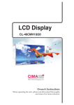
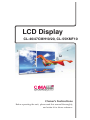
LCD Display
CL-46/47CMH10/20, CL-55KMF10
aVVUU
Owner’s Instructions
Before operating the unit, please read this manual thoroughly,
and retain it for future reference.
This multi-LCD Display system supports high resolution and multi-screen formatGG
G127UGSo these monitors can be used individually or all together.
There are various designs such as wall-mounting or stand-alone type for the best
installation.
You can connect the player directly to the LCD Display or network for a remote
control.
- 3rovides real-time information like weather and traf¿c reports, stock market
information, etc.
- Provides display solution used as in-store mediums to present product
advertisement, full motion video, photo-realistic graphics, text and animation.
- Designed for simple installation and maintenance
- Cost ef¿cient for maintenance and handling.
- Needs only a small space because of the ultra slim LCD Display.
j
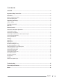
CAUTION .......................................................................................................................................2
Important Safety Instruction........................................................................................................3
Precaution .....................................................................................................................................4
Before considering as a failure ...........................................................................................................................4
About LCD display panel .....................................................................................................................................4
Unpacking and Setup ...................................................................................................................5
Scope of Supply .................................................................................................................................................5
Viewing the control ......................................................................................................................5
Rear View .............................................................................................................................................................5
Remote Control.............................................................................................................................6
Connection and start Operation..................................................................................................7
Connecting the Cables .......................................................................................................................................7
Connecting to a Computer ...................................................................................................................................8
Connecting to External Devices with Component Input ......................................................................................8
Connecting Several Devices ...............................................................................................................................8
Inserting the Batteries ..........................................................................................................................................9
Settings ......................................................................................................................................10
Switching on ......................................................................................................................................................10
Switching Off .....................................................................................................................................................10
Setting up for Operation ....................................................................................................................................10
DIP Switch Setting(No.0~69) .............................................................................................................................11
DIP Switch Setting(No.70~128)..........................................................................................................................12
..................................................................................................13
Setting ID Example for LCD display panel
Connecting RS-232C Cable ..............................................................................................................................13
Connecting S-Video Cable ..............................................................................................................................14
..............................................................................................................................14
Connecting VGA Cable
Connecting the Power Cord ..............................................................................................................................15
AC Power Connection ........................................................................................................................................15
Set Screen Language ........................................................................................................................................16
Set Geometry .....................................................................................................................................................16
Set MISC. ..........................................................................................................................................................16
Select Source (Main Input) .................................................................................................................................17
Troubleshooting .........................................................................................................................18
Technical Speci¿cations ............................................................................................................19
Memo ...........................................................................................................................................20
English
1
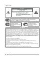
jh|{pvu
CAUTION
RISK OF ELECTRIC SHOCK.
DO NOT OPEN
CAUTION : TO PREVENT ELECTRICAL SHOCK,
DO NOT REMOVE REAR COVER.
NO USER SERVICEABLE PARTS INSIDE.
REFER SERVICING TO QUALIFIED SERVICE
PERSONNEL.
The /ightning Àash and arrow head within the triangle is a warning sign
alerting you of ³dangerous Yoltage´ inside the product.
This symbol indicates
additional safety instructions
in the te[t.
This symbol indicates
instructions to facilitate
the operation.
FCC NOTICE
This device has been tested and found to comply with the limits for a Class B device, pursuant to
Part 15 of the FCC Rules. These limits are designed to provide reasonable protection against harmful
interference in home environment as well as in a commercial, industrial or business environment.
This equipment can generate, use and radiate radio frequency energy and, if not installed and used in
accordance with the instruction, may cause harmful interference to radio communications. However,
there is no guarantee that interference will not occur in a particular installation. If this equipment does
cause harmful interference to radio or Monitor reception, which can be determined by turning the
equipment off and on, the user is encouraged to try to correct the interference by one or more of the
following measures:
- Reorient or relocate the receiving antenna.
- Increase the separation between the equipment and receiver.
- Connect the equipment into an outlet on a circuit different from that to which the receiver is
connected.
- Consult the dealer or an experienced radio/LCD display panel technician for help.
Changes or modi¿cation not expressly approved by the party responsible for compliance could void
the user’s authority to operate the equipment.
Connecting of peripherals requires the use of grounded shielded signal cables.
2
English
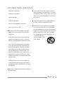
pGz Gp
Read these instructions.
Keep these instructions.
Heed all warnings.
Follow all instructions.
Use only with a cart, stand, tripod, bracket or
table speci¿ed by the manufacturer or sold with
the apparatus. When a cart is used, use caution
when moving the cart/apparatus to avoid injury
from tip-over.
Unplug this apparatus during lightning storms
or when unused for long periods of time.
Do not use this apparatus near water.
Clean only with a dry cloth.
Do not block any of the ventilation openings.
Install in accordance with the manufacturer’s
instructions.
Do not install near any heat sources such as
radiators, heat registers, stoves, or other apparatus (including ampli¿ers) that produce heat.
Refer all servicing to quali¿ed service personnel. Servicing is required when the apparatus
has been damaged in any way, such as power
supply cord or plug is damaged, liquid has been
spilled or objects have fallen into the apparatus, the apparatus has been exposed to rain
or moisture, does not
operate normally, or has
been dropped.
Do not defeat the safety purpose of the polarized or grounding type plug. A polarized plug
has two blades with one wider than the other.
A grounding type plug has two blades and a
third grounding prong. The wide blade or the
third prong is provided for your safety. When
the provided plug does not ¿t into your outlet,
consult an electrician for the replacement of the
obsolete outlet.
Protect the power cord from being walked on
or pinched particularly at plugs, convenience
receptacles and the point where they exit from
the apparatus.
Only use the attachments/accessories speci¿ed
by &,0$'LJLWHF
English
3
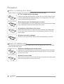
w
GiGGGGGG
Before calling for any repair, check the following and then refer to a near A/S center.
X “Tick” sound from the main body.
If there is no problem with the screen or sound, the “tick” sound is likely to result
from the cabinet lightly shrinking with change of room temperature. The sound
does not affect product’s performance.
X No image at upper and bottom part of screen.
As for a screen which is over 16:9 in width (such as cinema-sized one) no image
may be displayed at upper and bottom part of the screen.
X Speckles or white lines on the screen
Check whether the problem is caused by vehicle, streetcar, high voltage cable
or neon sign, which intererence wave or electromagnelic induction. Avoid any
intering object.
X Screen size can be changed.
The screen size may be ¿tted to the ¿rst dark scene depending on contents.
GhGsjkG GG
The followings are phenomena caused by characteristics of the LCD display panel. Since it is not any
failure, you may use it at rest.
X Black or twinkling sports on the screen
Although the LCD display panel is manufactured with high-precision technology,
there may exist black or twikling sports on the screen. Since it is not any failure,
you may use it at rest.
X Noise From the inside
When you turn on the prouct, driving sound may be heard from the display panel.
Since it is not any failure, you may use it at rest.
4
English
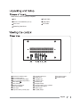
Please check, that the delivery is complete.
1
2
3
4
5
6
7
8
9
10
1
Unit
5
Serial Cable
2
Remote control & Batteries (AA x 2)
6
VGA Cable
3
Power Cord
7
DVI Cable
4
Operating Instructions
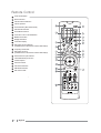
Input Source selection button
Menu Selection button
Menu Control button(Left, Right)
Menu Control button(Top, Bottom)
Power button( )
Power Indicator
Remote Control Sensor
Power Switch(Main)
Power Input
Component Video (Y Pb Pr) Input
11
12
13
14
15
16
17
18
19
20
Composite Video Input
S-Video Input
PC (RGB) Input
PC (DVI-D) Input
RS-232C Input
ID No(DIP Switch)
Component Video (Y Pb P r) Output
Composite Video Output
S-Video Output
PC (RGB) Output
21
22
PC (DVI-D) Output
RS-232C Output
English
5
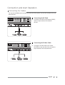
yGj
1
Power On/Off button
2
Numeric buttons
3
Favorite Channel Selection
4
Volume Up/Down
5
Sound Selection (Mono/Stereo/SAP)
6
Picture Mode Selection
7
Sound Mode Selection
8
Control the Cursor in the OSD Menu
9
MENU Con¿rmation
10
Display OSD Menu
11
Information Display
12
DVD Player Function Buttons
(Available in the model that has a built-in DVD Player)
13
Temporary Sound Mute
14
DVD Player Function
(Available in the model that has a built-in DVD Player)
15
External Source Input Selection
16
Internet/Media Player Function
17
Closed Captions
18
Previous Channel
19
Picture Size Selection
20
SRS WOW Selection
21
Exit from the OSD
6
English
jGGGv
GjGGjGG
You can use the Monitor set to connect camcorder and video games. Use the cinch sockets on the rear
side of the unit.
Connecting the AV Cable
1
Connect the AV cable to the sockets [VIDEO]
and the output sockets of the external
devices.
Connecting the S-Video Cable
1
Connect the S-Video cable to the socket
[S-VIDEO] on the rear side of the unit and the
output sockets of the external devices.
English
7
GjGGGjG
Use a 15-pin D-Sub cable or DVI-D cable to connect the LCD display panel set to the computer.
1
2
3
Plug the cable into the output socket of the
graphic board.
Plug the other end of the cable into the socket
[RGB] or [DVI-D].
Adjust the settings of the Monitor picture
corresponding to the settings for Monitor
operation. See “Settings” on page 10.
If the LCD display panel does not receive any signal, adjust the output of the
computer. For information on how to setup the computer, refer to the
corresponding manual of the computer.
GjGGlGkGGjGpG
You can use the LCD display panel to connect DVD recorder/player and set-top-box. Connect the audio
and video cables from the external equipment’s output jacks to the LCD display panel input jacks, as
shown in the ¿gure. When connecting the LCD display panel to external equipment, match the jack
colours.
Connecting to External Devices
1
2
Plug the video cable according into the colours
to the output sockets of the external devices.
Plug the other end of the video cable according
to the colours into the [Y, Pb, Pr] sockets on the
LCD display panel.
GjGzGkG
You can use the connections described parallel . On how to select the desired source see “Select
Source” on page 20 and “Select Signal Source for PIP” on page 20.
8
English
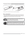
GpGGiG
For the operation of the remote control 2 type R03 1.5V Size AA batteries are included in the delivery.
1 Remove the cover on the back of the remote control and insert the batteries.
Notes on Handling Batteries
When used properly batteries are a safe and reliable source of energy. However, when misused or not
used according to the intention, they may leak. In extreme cases there is a danger of explosion or ¿re.
Therefore please understand that the manufacturer will not be liable in case of misuse or improper use.
For detailed information on how to handle the batteries, please contact the respective
manufacturer.
ƒ :hen inserting the batteries, ensure the polarity is matched correctly
(+ and - marking on the battery and on the unit.
ƒ Never try to recharge non-rechargeable batteries.
Disposal of batteries is clearly regulated by legal acts. Consumer Tuantities
of batteries must be taken back by the dealer or by local public collectors.
Never discharge batteries together with common waste. Make use of the free
public collection system Protect your environment. Return used batteries.
English
9
zG
GzGG
1 Press the power switch on the back of the unit.
2 Press
on the remote control.
This switches the unit on and it can be operated using the remote control.
If it is not explicitly stated otherwise, it will be assumed that the unit and the
LCD display panel set are switched on and will be operated by the remote
control.
By default, the unit is set to the english language. For information on how to
change the on-screen language later, refer to: “Set Screen Language” on
page 16.
GzGvG
Stand by
1 Press
on the remote control.
Please note that the unit also consumes a little power when in stand by mode.
Switch Stand by Off
1 Press the power switch on the back of the unit.
Now the unit is switched off completely and does not consume any power.
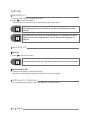
GzGGGvG
You can adjust various settings of the unit to adapt it to your requirements.
10
English
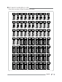
GkpwGzGzOuUW¥]`PG
Each Screen must have a unigue ID number by DIP switch.
English
11
GkpwGzGzOuU^W¥XY^P
Each Screen must have a unigue ID number by DIP switch.
12
English
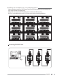
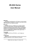
GzGpkGGGsjkG G
When connecting a number of LCD Dispay Panel through Displaychain(Link), surrounding noise
may come out lower the image quality.
Daisy chain can connect with LCD display panel to maximum 16EA. (by DVI)
But, If you need additional connection, you must connect daisy chainusing distributer.
LCD ID1
LCD ID2
LCD ID3
LCD ID4
LCD ID5
LCD ID6
LCD ID7
LCD ID8
LCD ID9
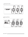
Connecting RS-232C Cable
English
13
Connecting S-video Cable
Connecting VGA Cable
14
English
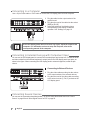
1
Connect the supplied power cord.
Don,t plug another AC power cord into extension cord. It’s a good to start a
re.The maximum current is 15A in normal extension cord.
The maximum current must be restricted 15A.
-The Model CL-46/47CMH10/20 can be con gured serially maximum 4 SETS in USA (AC100V).
-The Model CL-46/47CMH10/20 can be con gured serially maximum 10 SETS in Europe (AC220V).
-The Model CL-55KMF10 can be con gured serially maximum 4 SETS in USA (AC100V).
-The Model CL-55KMF10 can be con gured serially maximum 10 SETS in Europe (AC220V).
English
15
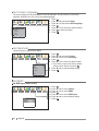
GzGzGsG
The screen display text can be displayed in several languages. Use this function to set screen
language. By default, the unit is set to the english language.
Picture
Audio
Mode
Brightness
Mode
Contrast
Standard
Black Level
Sport
Sharpness
Natural
Colour
Mild
Tint
Custom
Move
Timer
Channel
Setup
Option
Custom
OK
50
50
50
50
50
Select
MENU
1
2
3
4
5
6
7
Press
.
Press Ż or Ź and select Setup.
Press Ÿ or ź and select OSD Language.
Press
.
Press Ÿ or ź to select the desired setting.
Press
to save the setting.
Press
.
Back
GzGn Use this function to adjust screen status.
Picture
Audio
Timer
Channel
Setup
Option
OSD Language
AV Out
Geometry
Input label
Geometry
Video Input Select
Auto Adjust
Clolk Zoom Mode
1792
Phase Parent
18
H.Position
3
Caption
V.Position
-5
H.Size
V.Size
Reset
Move
OK
Enter
MENU
1
2
3
4
5
Press
.
Press Ż or Ź and select Setup.
Press Ÿ or ź to select Geometry.
Press
.
Press Ÿ or ź to select the desired menu.
Ƈ If you want to reset to the factory default
.
setings, select “Reset” and press
6 Press Ż or Ź to adjust desired setting.
7 Press
.
Back
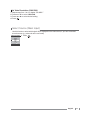
GzGtpzjUG
Set RGB Input (Video or PC)
Picture
Audio
Timer
Channel
Setup
No Signal Off
No Operation Off
Local Lock
Noise Reduction
MISC.
RGB Input
1280/1360
HDMI Audio
Move
16
English
Adjust
MISC.
PC
1360
PC
MENU
Back
Option
1
2
3
4
5
6
7
Press
.
Press Ż or Ź to select Option.
Press Ÿ or ź to select MISC.
Press
.
Press Ÿ or ź to select RGB Input.
Press Ż or Ź to select desired setting.
Press
.
Set Video Resolution (1280/1360)
1
2
3
4
Repeat steps from 1 to 4 in chapter “Set MISC.”
Press Ÿ or ź to select 1280/1360.
Press Ż or Ź to select desired setting.
Press
.
GzGzGOtGpP
Use this function to select which signal will be displayed on the main screen, if you have connected
several sources (e.g. a decoder and a roof aerial).
1 Press
Main Input
Video
S-Video
.
YPbPr
RGB
DVI
Move
OK
Select
G
English
17
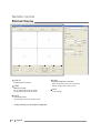
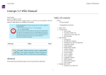
yGj
GDefault Display
1
1
2
2
4
3
COM SET
4
5
ZOOM
Communications Port Setup
Display enlargement / reduction
PANEL
Real : Display full screen on each panel
Zoom : Display full screen on 2x2
Multi Screen Setup
Set up number of screen on X-Axis
Set up number of screen on Y-Axis
3
INPUT
Select input source
Select input source on chosen screen
GTo adjust settings, you should press “Apply”key.
18
English
5
SAVE
Save settings
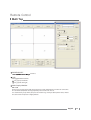
yGj
G Multi Tap
1
2
3
4
5
1
POWER ON/OFF
u choose.
2
GAP
Set up gap between screens.
3
4
5
: Fix gap up-and-down.
: Fix gap left-and-right.
Multi Display Window
APL Code
Each unit set exchanges hte APL (Average Picture Level) information each other on same time.
The controller (APC) feeds back appropriate picture level each unit set.
It is automatically set up when you press the “zoom” key, and if you add optional code, choose
the code value and press the “Apply”button.
English
19
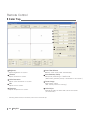
yGj
G Color Tap
1
2
3
4
5
8
6
7
9
1
Brightness
6
hGGGU
2
Contrast
7
hGGGU
3
4
8
Sharpness
hGzGGU
Freeze Image
zG¡TU
OGiSG GGGUGP
Tint
hGGGU
5
Auto Geometry Setup
zGGGGˈyniˉU
OG~GG GSGGGGGTGP
Color Saturation
hGGGGU
Auto Color Balance
iGGGG U
9
Color Adjust
jGGGGGGGGGU
OGYWGGuGP
GoGGGGGGGyGU
20
English
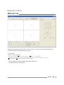
yGj
Remote Tap
U Remote tap is used to set up for “Multi”, “Color”, “Picture”. It can also substitute for the operation
of remote control unit for additional adjustment.
U Factory Mode
Choose “Set” for Factory Mode.
GjGˈtˉGGGGGGjGˈvˉGGGGGGjˈXT[T[T]ˉ
pGGGGGGGGGGGGGGGG
jˈlˉGGGGGnG GGGˈm Gtˉ
- Choose “Expert”, be able to adjust white balance with R, G, B
- To initialize, choose “Factory Reset”
English
21
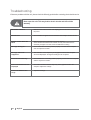
{
If there are problems with the unit, please check the following points before contacting the technical service.
Never open the unit. This may lead to electric shocks and will void the
warranty.
No Picture or Sound
Make sure the receiver and the LCD display panel set are both connected to
the power.
Black Screen
Remote Control Does Not
Work
Check whether a signal source is selected. See chapter “Select Source”
Make sure the unit is connected to the power sourrce.
Check whether the batteries are inserted correctly and whether the are
suf¿ciently charged. To do this, insert new batteries for testing.
Message “No Signal “
Check wether the connecting cable is properly connected to the computer
and the respective sockets.
Message “Video not
Supported”
The resolution or the frequency of the graphic board in the computer
cannot be displayed. Change the settings in the computer.
Picture Scrolls Vertically
Check wether the connecting cable is properly connected to the computer
and the respective sockets.
Parts of the Picture are not
Displayed
Check the resolution and the frequency of the graphic board in the
computer. Adjust the settings.
Picture Too Small or Too
Large
Adjust the settings.
22
English
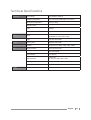
{Gz
n
Input voltage
AC 100-240 V, 50/60 Hz
Operating temperature
5°C to 35°C (CL47CMH10/20: 0°C to 50°C)
Environment temperature
-20°C to +60°C
Remote control
sjk
}
Type
Infrared
Battery
Type R03 1.5 V Size AA
Pixel
1366 x RGB x 768
(CL55KMF10: 1920 x RGB x 1080)
Type
a-Si TFT active matrix
Video system
CVBS, S-Video, RGB
jGp Y/Pb/Pr
wj
Synchronization
Component 1/2; 480i/p, 576i/p, 720p, 1080ip
30~61 kHz horizontal
56~75 Hz vertical
~li
Colour display
16,7 M (true)
Resolution Max.
1366 x 768
(In case of Full HD 1920 x 1080)
Input signal
DVI,RGB
Synchronization H/V separated
Positive or negative
MMC
Internet/Media player
English
23
t
24
English