1
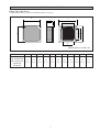
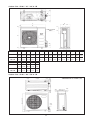
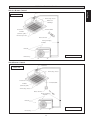
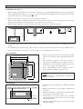
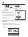
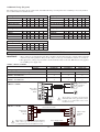
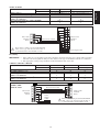
INSTALLATION MANUAL
Model: IM-CKA-0501-ACSON
CEILING CASSETTE
SPLIT TYPE AIR CONDITIONER
(A Series)
CEILING CASSETTE
OUTLINE AND DIMENSIONS
Indoor Unit (CKA Series)
• (With Wireless Remote Control & With Wired Remote Control)
B
F
C
D
E
J
I
G
A
H
M
All dimensions are in mm / (in)
MODEL
A
B
C
D
E
F
G
H
I
J
K
CK / 5CK 20A/AR
CK / 5CK 25A/AR
CK / 5CK 30A/AR
CK 40A/AR
820
820
363
335
28
930
930
642
622
555
555
(32,2)
(32,2)
(14,3)
(13,2)
(1,1)
(36,6)
(36,6)
(25,2)
(24,5)
(21,9)
(21,9)
CK 50A/AR
i
Outdoor Unit (SL - B Series)
39 (1,5)
840 (33,1)
124 (4,9)
592 (23,3)
840 (33,1)
124 (4,9)
5 (0,2)
297 (11,7)
330 (13,0)
160 (6,3) 85
A
B
C
D
E
F
G
H
840
646 330 297
309 626
41
(33,1) (25,4) (13,0) (11,7) (12,2) (24,6) (1,6)
ii
85
(3,3)
J
K
75
(3,0)
177
(7,0)
106
(4,2)
L
M
N
P
(2,6) (3,0)
65 75
20 (0,8) 177 (7,0)
626 (24,6)
646 (25,4)
20 (0,8)
309 (12,2)
20 (0,8)
Dimension
20B / 20BR
25B / 25BR
30B / 30BR
141
(5,6)
2,5 (0,1)
(3,3)
41
(1,6)
78,5 (3,1)
5 (0,2)
39 (1,5)
408 (16,1)
378 (14,9)
330 (13,0)
15 (0,6)
15 (0,6)
All dimensions are in mm / (in)
Q
R
106 408 378
124 592 78,5
(4,2) (16,1) (14,9) (4,9) (23,3) (3,1)
Outdoor Unit : SL20C / 25C / 28C & CR
K
L
All dimensions are in mm / (in)
P
N
C
M
N
L
G
H
S
T
B
FOR SL25C/CR
ONLY
E
F
Q
C
A
D
O
R
I
Dimension
A
B
C
D
E
J
F
G
H
I
J
K
L
M
N
O
20C/CR
855
628
(33,7) (24,7)
328
508
181
(12,9) (20,0) (7,1)
44
(1,7)
93
(3,7)
149
(5,9)
101
(4,0)
113
(4,4)
603
(23,7)
126
(5,0)
164
(6,4)
17
(0,7)
49
(1,9)
25C/CR
28C/CR
855
730
(33,7) (28,7)
328
513
182
(12,9) (20,2) (7,2)
44
(1,7)
93
(3,7)
149
(5,9)
101
(4,0)
113
(4,4)
603
(23,7)
126
(5,0)
164
(6,4)
17
(0,7)
47
(1,9)
Dimension
P
Q
R
S
T
20C/CR
32
(1,3)
3
(0,1)
23
(0,9)
73
(2,9)
75
(3,0)
25C/CR
28C/CR
32
(1,3)
3
(0,1)
23
(0,9)
73
(2,9)
75
(3,0)
Outdoor Unit : SL30C / 40C / 50C & CR
141,5
(5,6)
All dimensions are in mm / (in)
20,0
(0,8)
746,5
(29,4)
448,0
(17,6)
141,5
(5,6)
850,0 (33,5)
20,0
(0,8)
1030,0 (40,6)
25,0 (1,0)
50,0
(2,0)
85,0
(3,3)
iii
40,0
(1,6)
400,0 (15,7)
320,0 (12,6)
40,0
(1,6)
Sharp edges and coil surfaces are potential locations which may cause
injury hazards. Avoid from being in contact with these places.
! Caution
! Avertissement
Les bords coupants et les surfaces du refroidisseur tuulaire présentent
un risque de blessure. Mieux vaut éviter le contact avec ces endroits.
! Vorsicht
Scharfe Kanten und Wärmetauscherflächen stellen eine Gefahrenquelle dar.
Jeglicher Kontakt mit diesen Stellen ist zu vermeiden.
! Cautela
Per preservarsi da eventuali ferite, evitare di toccare gli spigoli afilati e la
superficie dei serpentini.
Los Bordes afilados y la superficie del serpentín pueden producir lesiones.
Evite tocarlos.
! Cuidado
! Осторожно
Острые края и поверхности змеевиков являются
потенциальными местами нанесения травм. Остерегайтесь
контакта с этими местами.
NOTICE
This product is subjected to Waste of Electrical and Electronic Equipment Regulations (WEEE
Regulations). The waste product shall be separately collected by specific collection and treatment centre.
Please refer to local authorithy for these centres. This is only applicable to European Union countries.
Ce produit est soumis à la ré
échets des é
électriques et
électroniques (ré
r
échet doit être collecté
t séparé
r ment par un centre de collecte
et de traitement spécifique. Veuillez vous ré
r fé
f
és locales pour connaî
aître ces centres. Ceci
éenne.
Dieses Produkt unterliegt den Bestimmungen zur Entsorgung von elektrischen und elektronischen
Gerää
ä
ätes
getrennt vom Hausmüll bei Ihrer örtlichen Mü
ö
äändiges Abfall-Amt. Dieser
Hinweis gilt nur fü
f r Länder
ä
der Europäischen Union.
Questo prodotto è soggetto alle disposizioni RAEE (Rifiuti di apparecchiature elettriche ed elettroniche).
à ritirato da un centro incaricato del ritiro e smaltimento. Per conoscere il
nome del centro pertinente, contattare le autoritàà locali. Questa disposizione è valida solamente i paesi
dell’U.E.
éctrico y Electrónico en materia de
í
ífico
ñado será
de colecció
í
ón Europea.
данного
по
и
.
правила
,
Европейского
iv
. Эти
.
English
INSTALLATION MANUAL
This manual provides the procedures of installation to ensure a safe and good standard of operation for the air
conditioner unit.
Special adjustment may be necessary to suit local requirements.
Before using your air conditioner, please read this instruction manual carefully and keep it for future reference.
CEILING CASSETTE SPLIT TYPE AIR CONDITIONER
MODEL
COOLING ONLY
HEAT PUMP
CK20A / ACK20A
SL20C / ALC20C
4SL20B / A4LC20B
CK20AR / ACK20AR
SL20CR / ALC20CR
4SL20BR / A4LC20BR
5CK20A / A5CK20A
5SL20C / A5LC20C
5CK20AR / A5CK20AR
5SL20CR / A5LC20CR
CK25A / ACK25A
SL25C / ALC25C
4SL25B / A4LC25B
CK25AR / ACK25AR
SL25CR / ALC25CR
4SL25BR / A4LC25BR
5CK25A / A5CK25A
5SL25C / A5LC25C
5CK25AR / A5CK25AR
5SL25CR / A5LC25CR
CK30A / ACK30A
SL28C / ALC28C
SL30C / ALC30C
4SL30C / A4LC30C
CK30AR / ACK30AR
SL28CR / ALC28CR
SL30CR / ALC30CR
4SL30CR / A4LC30CR
5CK30A / A5CK30A
5SL28C / A5LC28C
5SL30C / A5LC35C
5CK30AR /A5CK30AR
5SL28CR / A5LC28CR
5SL30CR / A5LC35CR
CK40A / ACK40A
SL40C / ALC40C
4SL40C / A4LC40C
CK40AR / ACK40AR
SL40CR / ALC40CR
4SL40CR / A4LC40CR
5CK40A / A5CK40A
5LC35C / A5LC35C
5SL40C / A5LC40C
5CK40AR / A5CK40AR
5LC35CR / A5LC35CR
5SL40CR / A5LC40CR
CK50A /ACK50A
SL50C / ALC50C
4SL50C / A4LC50C
CK50AR / ACK50AR
SL50CR / ALC50CR
4SL50CR / A4LC50CR
5CK50A / A5CK50A
5SL50C / A5LC50C
5CK50AR / A5CK50AR
5SL50CR / A5SL50CR
IM-CKA-0501(2)-Acson
Part No.:A08019025475
1-1
CONTENTS
- Outline And Dimensions
- Safety Precautions
- Installation Diagram
- Installation Of The Indoor Unit
- Installation Of The Outdoor Unit
- Refrigerant Piping Work
- Electrical Wiring Connection
- Special Precautions When Dealing With R410A Unit
- Special Precautions When Dealing With R407C Unit
- Vacuuming And Charging
- Special Precautions When Charging Unit With
Copeland Scroll Compressors
- Accessory Parts
- Indicator Lights
- Overall Checking
- Standard Operation Conditions
- Auto Random Re-start Function
- Service And Maintenance
- Troubleshooting
- Phase Sequencer (Optional)
page i – iv
page
2
page
3
page
4
page
6
page
7
page
8
page 11
page 11
page 11
page
page
page
page
page
page
page
page
page
SAFETY PRECAUTIONS
Before installing the air conditioner unit, please read the following safety precautions carefully.
! Warning
•
Installation and maintenance should be performed by qualified persons who are familiar with local code and
regulation, and experienced with this type of appliance.
•
All field wiring must be installed in accordance with the national wiring regulation.
•
Ensure that the rated voltage of the unit corresponds to that of the name plate before commencing wiring work
according to the wiring diagram.
•
The unit must be GROUNDED to prevent possible hazard due to insulation failure.
•
All electrical wiring must not touch the refrigerant piping or any moving parts of the fan motors.
•
Confirm that the unit has been switched OFF before installing or servicing the unit.
! Caution
Please take note of the following important points when installing.
• Do not install the unit where leakage of flammable gas may occur.
If gas leaks and accumulates around the unit, it may cause fire ignition.
• Ensure that the drainage piping is connected properly.
If the drainage piping is not connected properly, it may cause water leakage which will dampen the
furniture.
• Do not overcharge the unit.
This unit is factory pre-charged. Overcharge will cause over-current or damage to the compressor.
• Ensure that the units panel is closed after service or installation.
Unsecured panels will cause the unit to operate noisily.
1-2
12
13
13
14
15
15
15
16
16
INSTALLATION DIAGRAM
English
Wireless Remote Control
Drain Hose
Indoor unit
Air Discharge Louver
IR Receiver
LED Light
Front Panel
Air Intake Grille
Air Filter
(behind the grille)
Air Discharge Louver
Remote Control
Refrigerant Piping
Air Intake
Air Intake
Outdoor unit
Air Discharge
Wired Remote Control
Drain Hose
Indoor unit
Air Discharge Louver
Front Panel
Air Intake Grille
Air Filter
(behind the grille)
Air Discharge Louver
Remote Control
Refrigerant Piping
Air Intake
Air Intake
Outdoor unit
Air Discharge
1-3
INSTALLATION OF THE INDOOR UNIT
Preliminary Site Survey
• Electrical supply and installation is to conform to local authority's (e.g. National Electrical Board) codes and regulations.
• Voltage supply fluctuation must not exceed +10% of rated voltage. Electricity supply lines must be independent of welding
transformers which can cause high supply fluctuation.
• Ensure that the location is convenient for wiring, piping and drainage.
• The indoor unit must be installed in such that is free from any obstacles in path of cool air discharge and warm air return,
and must allow spreading of air throughout the room (near the center of the room).
Min. 0.5 m
Min. 0.5 m
Max. 0.3 m
Max. 3.0 m
Min. 1.0 m
Beam
• Must be provide clearance for the indoor unit from the wall and obstacles as shown in the figure.
Min. 0.5 m
Obstacle
Floor
• The installation place must be strong enough to support a load 4 times the indoor unit weight to avoid amplifying noise and
vibration.
• The installation place (hanging ceiling surface) must be assuring levelness and the height in the ceiling is 350mm or more.
• The indoor unit must be away from heat and steam sources (avoid installing it near an entrance).
Unit Installation
• Measure and mark the position for the hanging rod. Drill
the hole for the angle nut on the ceiling and fix the hanging
rod.
890.0 mm (Ceiling board opening)
790.0 mm (Hanging rod)
890.0 mm (Ceiling board opening)
Unit
Unit size 820.0mm
Unit size 820.0 mm
620.5 mm (Hanging rod)
• The installation template is extended according to
temperature and humidity. Check on dimensions in use.
• The dimensions of the installation template are the same
as those of the ceiling opening dimensions.
• Before ceiling laminating work is completed, be sure to
fit the installation template to the indoor unit.
NOTE
Be sure to discuss the ceiling drilling work with the
installers concerned.
Piping Direction
Unit Hanging
• Confirm the pitch of the hanging rod is 790mm × 620.5mm
sharp.
• Hold the unit and hang it on the hanging rod with the nut
and washer.
• Adjust the unit height to 35.0 mm between the indoor unit
bottom surface and the ceiling surface.
Indoor Unit
Ceiling
Board
35.0 mm
• Confirm with a level gauge that the unit is installed
horizontally and tighten the nut and bolt to prevent unit
falling and vibration.
• Open the ceiling board along the outer edge of the paper
installation template.
1-4
Drain Piping Work
• Avoid installing the drain pipe in up and down slope to
prevent reversed water flow.
• During the drain pipe connection, be careful not to exert
extra force on the drain connector at indoor unit.
Indoor Unit
• The outside diameter of the drain connection at the
flexible drain hose is 20mm.
Pipe Clamp
Good
Bad
• Be sure to execute heat insulation (polyethylene foam
with thickness more than 8.0mm) on the drain piping to
avoid the condensed water dripping inside the room.
Drain Test
• Connect the main drain pipe to the flexible drain hose.
Feed Water
• Feed water from flexible drain hose to check the piping
for leakage.
Main Drain Pipe
• When the test is completed, connect the flexible drain
hose to the drain connector on the indoor unit.
Flexible Drain Hose
NOTE
This Indoor Unit uses a drain pump for condensed water drainage. Install the unit horizontally to prevent water
leakage or condensation around the air outlet.
Panel Installation
• The front panel can only be fitted in one direction, follow the piping direction. (Follow piping arrow sticker on front
panel)
• Be sure to remove the installation template before installing the front panel.
Open
Screw
• Open the air intake grille by pulling back the catchers and removing it together with filter from panel.
• Install the front frame panel onto the indoor unit by 4 screws and tighten it completely to prevent cool air leakage.
• Connect the LED wire and air swing wire to the indoor unit.
Control Box
LED Wire
From
Front
Panel
Air Swing Wire
1-5
English
• Drain pipe must be in downward gradient for smooth
drainage.
NOTE
Install the front frame panel firmly to prevent cool air leakage which will cause condensation and water dripping.
Indoor Unit
Cool
Air
Cool
Air
Air Leak
Air Leak
Ceiling Board
Ceiling Board
Panel
Panel
Bad Installation
Good Installation
Air intake grille installation
Frame
(Optional Item)
• Before installing the air intake grille, be sure to fix the ionizer
filter to the air filter.
• Install the air intake grille together with the air filter to the
front panel.
Ionizer Filter
(Optional Item)
• The grille can be fit in any direction, when selecting direction,
the ceiling design and grille operability should be considered.
• If the unit comes with ionizer filter (optional item), make
sure to fix the ionizer filter to the air filter before installing
the air intake grille.
Filter
(Standard)
• Fix the ionizer filter to the air filter with the black side on top
and white side at bottom.
• Carefully clip on the ionizer filter frame.
INSTALLATION OF THE OUTDOOR UNIT
Preliminary site survey
• A place protected from rain, direct sunlight and well-ventilated wherever practicable.
• A place capable of bearing the weight of the outdoor unit and isolating noise and vibration.
• A place where there are no obstruction of air flow into or out the unit.
• Do not put any object which may become obstacle for the air flow into or out the outdoor unit.
• The location must not be susceptible to high concentration dust, oil, salt or sulfide gas.
Outdoor unit installation
• Install the outdoor unit firmly and horizontally. Maintain a space clearance from the obstruction as shown in below for
servicing and air ventilation.
A
B
C
D
SL series
A
B
C
D
Min. distance (mm)
300
1000
300
500
1-6
Refrigerant piping is important in particular. Refrigeration cycle of the split air conditioner is realized
by the perfect piping work.
Piping length and elevation
If the piping is too long, both the capacity and reliability of unit will drop. As the number of bends increase, resistance to
flow of refrigerant system increases, thus lowering cooling capacity and as a result the compressor may become defective.
Always choose the shortest path and follow the recommendation as tabulated below.
Model
Max. length (m)
Max. elevation (m)
Max. no. of bends
Liquid pipe size
Gas pipe size
Model
Max. length (m)
Max. elevation (m)
Max. no. of bends
Liquid pipe size
Gas pipe size
4SL20B/BR SL20C/CR 4SL25B/BR SL25/28C/CR
15
15
8
8
10
10
1/4”
3/8”
5/8”
5/8”
5SL20C/CR
15
8
10
1/4”
1/2”
5SL25C/CR
15
8
10
1/4”
5/8”
SL30C/CR
35
10
10
3/8”
5/8”
SL40C/50C/CR
35
10
10
3/8”
3/4”
5SL28C/CR
15
8
10
3/8”
5/8”
5SL35/40/50C/CR
35
10
10
3/8”
5/8”
Piping Connection
• Do not use contaminated or damaged copper tubing. If any piping, evaporator or condenser had been exposed or had been
opened for 15 seconds or more, then vacuum and purge with field supplied refrigerant. Generally, do not remove plastic,
rubber plugs and brass nuts from the valves, fittings, tubing and coils until it is ready to connect suction or liquid line into
valves or fittings.
• If any brazing work is required, ensure that nitrogen gas is passed through coil and joints while the brazing work is being
done. This will eliminate soot formation on the inside wall of copper tubings.
• Cut the pipe stages by stages, advancing the blade of pipe cutter slowly. Extra force and a deep cut will cause more
distortion of pipe and therefore extra burr.
• Remove burrs from cut edges of pipes with a remover. This will avoid unevenness on the flare face which will cause gas
leak.
• Align the center of the piping and sufficiently tighten the flare nut with fingers. Finally, tighten the flare nut with torque
wrench until the wrench clicks.
• Be sure to execute heat insulation. (polyurethane form with thickness more than 15 mm)
• Except the outdoor unit which is pre-charge with refrigerant R22, the indoor unit and the refrigerant connection pipes must
be purged because the air that contain moisture remaining in the refrigerant cycle may cause malfunction to the compressor.
1-7
English
REFRIGERANT PIPING WORK
Additional Charge (In gram)
The refrigerant is pre-charge in the outdoor unit, but additional charge of refrigerant after vacuuming is necessary. Follow
the recommendation as tabulated below.
Cooling Only (R22)
CK20A
CK25A
CK30A/40A/50A
Heatpump (R22)
10m
40
90
120
15m 20m 25m 30m 35m
110
270
380 640 900 1150 1410
CK20AR
CK25AR
CK30AR/40AR/50AR
Cooling Only (R407C)
CK20A
CK25A
CK30A/40A/50A
10m
40
80
120
10m
40
90
90
15m 20m 25m 30m 35m
110
270
280 460 650 830 1020
10m
40
80
80
15m 20m 25m 30m 35m
110
260
260 430 610 780 960
Heatpump (R407C)
15m 20m 25m 30m 35m
110
260
360 600 840 1090 1330
CK20AR
CK25AR
CK30AR/40AR/50AR
Cooling & Heatpump (R410A)
5CK20/25A/AR
5CK30/40/50A/AR
10m 15m 20m 25m 30m 35m
30 100
80 230 390 550 710 870
ELECTRICAL WIRING CONNECTION
Cooling Only
IMPORTANT:
* These values are for information only. They should be checked and selected to comply with local and/or
national codes and regulations. They are also subject to the type of installation and size of conductors.
** The appropriate voltage range should be checked with label data on the unit. ETL listed is only applicable to 60Hz power supply only.
CK20A / CK25A & CK30A
Model
Indoor
CK20A
CK25A
CK30A
Outdoor
SL20B/20C
SL25B/25C
SL28C/30C
Voltage range**
220-240V/1Ph/50Hz + ! or 208-230V/1Ph/60Hz+ !
Recommended fuse* (A)
16
20
25
Power supply cable size* (mm2)
2.5
2.5
4.0
Number of conductors
3
3
3
2.5
2.5
2.5
Interconnection cable size* (mm2)
Number of conductors
3
3
4
CK20A / 25A <> SL20B / 25B / 20C / 25C
CK30A <> SL28C
Interconnection Cable
COMP
COMP
L
Indoor Unit
Terminal
Block
N
N
N
Power
Supply
Cable
CK30A <> SL30C
COMP
!
There must be a double pole switch with
minimum 3mm contact gap and fuse/circuit
breaker as recommended in the fixed
installation circuit.
Interconnection Cable
L
Indoor Unit
Terminal
Block
COMP
L
N
N
N
L
!
Outdoor Unit
Terminal
Block
Power Supply Cable
There must be a double pole switch with minimum
3mm contact gap and fuse/circuit breaker as
recommended in the fixed installation circuit.
1-8
N
Outdoor Unit
Terminal
Block
Indoor
Outdoor
Model
5CK30/40A
CK40A
CK50A
5SL35C
SL40C
SL50C
380-420V/3Ph /50Hz+ N+ ! or 208-230V/3Ph/60Hz+N+ !
10/20
16/25
1.5/2.5
2.5/4.0
5
5
1.5/1.5
1.5/1.5
4
4
Voltage range**
Recommended fuse* (A)
Power supply cable size* (mm2) (50/60Hz)
Number of conductors
Interconnection cable size* (mm2) (50/60Hz)
Number of conductors
CK40A / CK50A <> SL40C / SL50C
COMP
L
N
COMP
Indoor Unit
Terminal
Block
L
R
Interconnection Cable
N
S
Outdoor Unit
Terminal
Block
T
N
!
There must be a double pole switch with minimum
3mm contact gap and fuse/circuit breaker as
recommended in the fixed installation circuit.
Power Supply Cable
Heat Pump
IMPORTANT : * These values are for information only. They should be checked and selected to comply with local and/or
national codes and regulations. They are also subject to the type of installation and size of conductors.
** The appropriate voltage range should be checked with label data on the unit.
CK20AR / CK25AR / CK30AR
Model
Indoor
Outdoor
CK20AR
CK25AR
CK30AR
SL20BR/20CR
SL25BR/25CR
SL28CR/30CR
220-240V/1Ph/50Hz+ ! or 208-230V/1Ph/60Hz+ !
16
20
25
2.5
2.5
4.0
3
3
3
2.5
2.5
2.5
5
5
6
Voltage range**
Recommended fuse* (A)
Power supply cable size* (mm2)
Number of conductors
Interconnection cable size* (mm2)
Number of conductors
CK20AR / 25AR <>
SL20BR / 25BR
SL20CR / 25CR
Outdoor Coil Sensor
4WV
OF
Indoor Unit
Terminal
Block
Interconnection Cable
COMP
4V
OF
COMP
L
N1
N2
N
Power
Supply
Cable
!
1-9
Outdoor Unit
Terminal
Block
There must be a double pole switch with minimum
3mm contact gap and fuse/circuit breaker as
recommended in the fixed installation circuit.
English
CK40A & CK50A
Outdoor Coil Sensor
CK30AR <> SL28CR
4WV
A
Interconnection Cable
4WV
Indoor Unit
Terminal
Block
OF
COMP
OF
COMP
Outdoor Unit
Terminal
Block
N
L
N
Power Supply Cable
L
N
E
N
!
There must be a double pole switch with
minimum 3mm contact gap and fuse/circuit
breaker as recommended in the fixed
installation circuit.
Outdoor Coil Sensor
CK30AR <> SL30CR
A
A
Interconnection Cable
4WV
Indoor Unit
Terminal
Block
4WV
OF
OF
COMP
COMP
L
L
N
N
Outdoor Unit
Terminal
Block
N
L
!
L
N
E
There must be a double pole switch with minimum
3mm contact gap and fuse/circuit breaker as
recommended in the fixed installation circuit.
N
CK40AR & CK50AR
Model
Indoor
Outdoor
Voltage range**
Recommended fuse* (A)
Power supply cable size* (mm2)
Number of conductors
Interconnection cable size* (mm2)
Number of conductors
5CK30/40AR
CK40AR
CK50AR
5SL35CR
SL40CR
SL50CR
380-420V/3Ph/50Hz +N+ ! or 208-230V/3Ph/60Hz+N+ !
10/20
16/25
1.5/2.5
2.5/4.0
5
5
1.5/1.5
1.5/1.5
7
7
Outdoor Coil Sensor
CK40AR / CK50AR <> SL40CR / SL50CR
A
4WV
OF
COMP
L
A
4WV
OF
Indoor Unit
Terminal
Block
!
COMP
L
N
Interconnection
Cable
N
Outdoor
Unit
Terminal
R
S
T
N
Power Supply
Cable
There must be a double pole switch with minimum
3mm contact gap and fuse/circuit breaker as
recommended in the fixed installation circuit.
1-10
R410A is a new HFC refrigerant which does not damage the
ozone layer. The working pressure of this new refrigerant is
1.6 times higher than conventional refrigerant (R22), thus
proper installation / servicing is essential.
• Never use refrigerant other than R410A in an air conditioner which designed to operate with R410A.
• POE oil is used as lubricant for R410A compressor, which
is different from the mineral oil used for R22 compressor.
During installation or servicing, extra precaution must be
taken not to expose the R410A system too long to moist
air. Residual POE oil in the piping and components can
absorb moisture from the air.
• To prevent mischarging, the diameter of the service port
on the flare valve is different from that of R22.
•
•
•
•
Use tools and materials exclusively for refrigerant R410A.
Tools exclusively for R410A are manifold valve, charging
hose, pressure gauge, gas leak detector, flare tools, torque
wrench, vacuum pump and refrigerant cylinder.
As an R410A air conditioner incurs higher pressure than
R22 units, it is essential to choose the copper pipes correctly. Never use copper pipes thinner than 0.8mm even
though they are available in the market.
If the refrigerant gas leakage occurs during installation /
servicing, be sure to ventilate fully. If the refrigerant gas
comes into contact with fire, a poisonous gas may occur.
When installing or removing an air conditioner, do not
allow air or moisture to remain in the refrigerant cycle.
SPECIAL PRECAUTIONS WHEN DEALING WITH R407C UNIT
•
•
•
R407C is a zeotropic refrigerant mixture which has zero
ozone depletion potential and thus conformed to the
Montreal Protocol regulation. It requires Polyol ester oil
(POE) oil for its compressor's lubricant. Its refrigerant
capacity and performance are about the same as the refrigerant R22.
POE oil is used as lubricant for R407C compressor, which
is different from the mineral oil used for R22 compressor.
During installation or servicing, extra precaution must be
taken not to expose the R407C system too long to moist
air. Residual POE oil in the piping and components can
absorb moisture from the air.
Refrigerant R407C is more easily affected by dust of moisture compared with R22, make sure to temporarily cover
the ends of the tubing prior to installation.
•
•
•
•
No additional charge of compressor oil is permitted.
No other refrigerant other than R407C.
Tools specifically for R407C only (must not be used for
R22 or other refrigerant).
i)
Manifold gauge and charging hose
ii) Gas leak detector
iii) Refrigerant cylinder/charging cylinder
iv) Vacuum pump c/w adapter
v) Flare tools
vi) Refrigerant recovery machine
Filter-dryer must be installed along the liquid line for all
R407C air conditioners. This is to minimise the contamination of moisture and dirt in the refrigerant system. Filterdryer must be of molecular sieve type. For a heat-pump system, install a two-way flow filter dryer along the liquid line.
VACUUMING AND CHARGING
Vacuuming is necessary to eliminate all moisture and air from the system. The series II Outdoor Unit is provided with flare
valve fittings.
Vacuuming
Charging
Before vacuuming, perform leak check for refrigeration
circuit. After the system piping are properly connected,
connect the flexible hoses to the correct charging nipples as
shown in the diagram. Ensure that flexible hose from charging
nipples are connected to the vacuum pump via standard
servicing valves and pressure gauges (gauge manifold).
Vacuum the air conditioner system to at least 500 microns
Hg. Do not start the unit when the system is engaged in
vacuuming.
Before charging, the vacuum must be held at 500 microns
Hg for at least 15 minutes, then break vacuum by charging
R-22 refrigerant. Operate the unit for 15 minutes and ensure
the refrigerant charges is of correct by monitoring running
current, gas and liquid line pressures. Suction and discharge
pipe pressure should be in the region of 75 psig and 275 psig
generally.
After ensuring the system is correctly charged, remove
flexible hose from charging nipples and replace caps.
1-11
English
SPECIAL PRECAUTIONS WHEN DEALING WITH R410A UNIT
SPECIAL PRECAUTIONS WHEN CHARGING UNIT WITH
COPELAND SCROLL COMPRESSORS
These precautions are intended for use with Copeland Scroll compressors only with R22, R407C, R134A, R404A, R507 and
R410A refrigerants but are not applied to Copeland reciprocating compressors or competitive Scroll compressors.
Scroll compressors have a very high volumetric efficiency and quickly pump a deep vacuum if there is insufficient refrigerant
in the system or if refrigerant is added too slowly. Operation with low suction pressure will quickly lead to very high discharge
temperatures. While this process is happening, the scrolls are not being well lubricated – scrolls depend on the oil mist in the
refrigerant for lubrication. A lack of lubrication leads to high friction between the scroll flanks and tips and generates additional
heat. The combination of heat of compression and heat from increased friction is concentrated in a small localized discharge
area where temperatures can quickly rise to more than 300˚C. These extreme temperatures damage the Scroll spirals and the
orbiting Scroll bearing. This damage can occur in less than one minute especially on larger compressors. Failure may occur in
the first few hours or the damage done during field charging may show up some time later.
Other typical field charging problems include undercharging, overcharging, moisture or air in the system etc. In time each one
of these problems can cause compressor failure.
Minimal equipment is required for field charging. The minimum equipment required to do a satisfactory job is:Set of service gauges
Vacuum gauge
Hoses
Scales
Vacuum pump
Thermometer
The proper refrigerant charge should follow the volume as recommended by manufacturer and recommendation should be
followed by the installer.
1. Charging procedures – Single phase compressors
Evacuate the system to 500 microns Hg. (67Pa). To reduce evacuation time, use short, large diameter hoses and connect to
unrestricted service ports on the system. Quality of vacuum cannot be determined by time – a reliable vacuum gauge must
be used. (etc. electronic vacuum gauge)
Turn the refrigerant cylinder upside down, purge the charging hose and charge liquid through the liquid line charging port
until refrigerant no longer flows or until the correct charge has been weighed in. If additional charge is required start the
system and slowly bleed liquid into the suction side until the system is full.
Copeland recommends charging liquid in a CONTROLLED manner into the suction side until the system is full.
This recommendation does not hold true for reciprocating compressors where liquid charging into the suction side could
cause severe damage.
Carefully monitor the suction and discharge pressures – ensure that the suction pressure does not fall below 25 psig (1.7
bar) at any time during the charging process.
! Caution
•
A
Manifold Gauge will show cylinder pressure rather than suction pressure if the cylinder valve and Manifold
valve “A” are both open.
There are many ways of charging liquid in a “controlled manner” into the suction
side:1. Use valve A on the manifold gauge set
2. Use the valve on the refrigerant cylinder
3. Charge through a Shredder valve
4. Use a hose with a Shredder valve depressor
5. Charge into the suction side at some distance from the compressor
6. All of the above
2. Charging procedures – Three phase compressors
The fundamental procedure is the same as for single phase models but the compressor can run in the wrong direction on
starting. If this happens reverse any two phases and start again. Short term reverse rotation will not damage the compressor.
All Specter compressors (Model: ZR90 to ZR19M) have internal discharge temperature protectors which are very effective
in preventing dangerously high discharge temperatures during charging. The protection module will trip and lock the
compressor out for 30 minutes. It is not normally necessary to wait 30 minutes for the module to reset. When the compressor
has cooled down the module can be reset by breaking the power supply to the control circuit. Very often the serviceman
does not understand why the module tripped and uses a jumper wire to bypass it. He continues to charge the system and
removes the jumper when charging is complete. The compressor may or may not run with the protector back in the circuit
but it is certain that the compressor has been damaged and premature failure is inevitable.
1-12
ACCESSORY PARTS
• The indoor unit is provided with air discharge and air intake “knock-out” hole for duct connection. However the connection of the short duct for air discharge is possible on only one side.
• The use of short duct for air discharge will improve airflow distribution if there is an obstruction (such as a lighting fixture)
or in a long, narrow room or an L-shaped room. It also use for air conditioning of two rooms simultaneously.
Possible Direction For Air Discharge And Air Intake
Air Discharge
Possible Opening Dimension For Duct Connection
Air Discharge
PCD Ø140
50
50
50
50
50
10
20
10
20
70
90
Ø100
115
Air Discharge
Air Intake
Air Discharge Knock Out Hole
Air Discharge
109
20
119
115
Air Intake
Knock Out Hole
NOTE
• Avoid using the short duct on which the air discharge grille can be completely closed, to prevent evaporator freezing.
• In order to prevent condensation forming, be sure that there is sufficient thermal insulation and no leakage of cool
air when installing the short duct.
• Keep the introduction of fresh air intake within 20% of total air flow. Also provide a chamber and use a booster fan.
Sealing Material
• It is possible to seal one of the four air discharge outlet. (sealing two or more air discharge outlet could cause a malfunction)
• Remove the front panel and insert the sealing material into the air discharge outlet on the indoor unit to seal the air outlet.
• The sealing material is the same length as the longer air discharge outlet. If it is desired to seal the shorter air discharge
outlet, cut the sealing material to shorten it.
• Push the sealing material in about 10 mm beyond the bottom surface of the indoor unit so that it does not touch the air
louver. Be sure not to push the sealing material in any farther than about 10 mm.
INDICATOR LIGHTS
Remote Control
When there is infrared remote control operating signal, the signal receiver on indoor unit will made a <beep> for signal
acceptance confirmation.
1-13
English
Short Duct Specification
LED
POWER
Blink 1 time
Blink 2 times
Blink 3 times
TIMER
-
SLEEP/HEAT
-
-
Blink 1 time
-
-
Blink 3 times
Blink 2 times
-
Other LEDs
Blink Fan
Blink Dry & Fan
Blink Dry
Faulty Indication
Room Sensor Open or Short
Indoor Coil Sensor Open
Outdoor Coil Sensor Open
Compressor Overload /
Blink Cool
Indoor Coil Sensor Short /
Outdoor Coil Sensor Short
Blink Cool & Dry Gas Leak
Blink Cool & Fan Water Pump Fault
Action
Call Your Dealer
OVERALL CHECKING
• Ensure that :1) The unit has been mounted solidly and rigid in position.
2) Piping and connections are leak proof after charging.
3) Proper wiring has been installed.
• Drainage check – pour some water into the main drain pipe from the flexible drain hose.
• Test run
1) Conduct a test run after water drainage test and gas leakage test.
2) Check the following items :a. Is the electric plug firmly inserted into the socket ?
b. Is there any abnormal sound from the unit ?
c. Is there any abnormal vibration on the unit itself or piping ?
d. Is the drainage of water smooth ?
• Confirm that :
1) Condenser fan is running, with warm air blowing off the condensing unit.
2) Evaporator blower is running and discharge cool air.
3) The remote control incorporate a 3 minute delay in the circuit. Thus, it requires about 3 minutes before the outdoor
condensing unit can start up.
1-14
STANDARD OPERATION CONDITIONS
Temperature
Minimum indoor
temperature
Maximum indoor
temperature
Minimum outdoor
temperature
Maximum outdoor
temperature
Ts °C / °F
Th °C / °F
19.4 / 66.9
13.9 / 57.0
26.7 / 80.1
19.4 / 66.9
19.4 / 66.9
13.9 / 57.0
46 / 114.8
24 / 75.2
Temperature
Minimum indoor
temperature
Maximum indoor
temperature
Minimum outdoor
temperature
Maximum outdoor
temperature
Ts: Dry bulb temperature.
! Warning
•
•
Ts °C / °F
Th °C / °F
10 / 50
–
26.7 / 80.1
–
-8 / 17.6
-9 / 15.8
24 / 75.2
18 / 64.4
Th: Wet bulb temperature.
Disconnect from the main power supply before servicing the air conditioner unit.
DO NOT pull out the power cord when the power is ON. This may cause serious
electrical shocks which may result in fire hazards.
AUTO RANDOM RE-START FUNCTION
If there is a power cut when the unit is operating, it will automatically resume the same operating mode when the power is
restored. (Applicable only to units with this feature)
! Caution
Before turning off the power supply, set the remote controller's ON/OFF switch to the “OFF”
position to prevent the nuisance tripping of the unit.
If this is not done, the unit's fans will start turning automatically when power resumes,
posing a hazard to service personnel or the user.
SERVICE AND MAINTENANCE
Service parts
Maintenance procedures
Period
Indoor air filter
1. Remove any dust adhered on the filter by using a vacuum cleaner or
wash in lukewarm water (below 40ºC) with neutral cleaning detergent.
2. Rinse well and dry the filter before placing it back onto the unit.
3. Do not use gasoline, volatile substances or chemical to clean the filter.
At least once every
2 weeks. More
frequently if
necessary.
Indoor unit
1. Clean any dirt or dust on the grille or panel by wiping it using soft cloth At least once every
soaked in lukewarm water (below 40ºC) with neutral detergent solution. 2 weeks. More
2. Do not use gasoline, volatile substances or chemical to clean the indoor frequently if
necessary.
unit.
! Caution
Do not operate any heating apparatus too close to the air conditioner unit. This may cause
the plastic panel to melt or deform as a result of the excessive heat.
1-15
English
Heat Pump Unit
Cooling unit
TROUBLESHOOTING
If any malfunction of the air conditioner unit is noted, immediately switch off the power supply to the unit.
Check the following fault conditions and causes for some simple troubleshooting tips.
Fault
Causes / Action
1. The compressor does not start operate after 3 minutes
from starting the air conditioner unit.
2. The air conditioner unit does not operate.
- Protection against frequent starting. Wait for 3 to 4
minutes for the compressor to start operating.
- Power failure, or the fuse need to be replaced.
- The power plug is disconnected.
- It is possible that your delay timer has been set incorrectly.
- If the fault persist after all these verifications, please
contact the air conditioner unit installer.
- The air filter is dirty.
3. The air flow is too low.
- The doors or windows are open.
- The air suction and discharge are clogged.
4. Discharge air flow has bad odor.
5. Condensation on the front air grille of the indoor unit.
6. Water flowing out from the air conditioner unit.
7. Hissing air flow sound from the air conditioner unit
during operation.
- The regulated temperature is not high enough.
- Odors may be caused by cigarettes, smoke particles,
perfume etc. which might have adhered onto the coil.
- This is caused by air humidity after an extended long
period of operation.
- The set temperature is too low, increase the temperature
setting and operate the unit at high fan speed.
- Switch off unit and call dealer.
- Refrigerant fluid flowing into the evaporator coil.
If the fault persists, please call your local dealer / serviceman.
PHASE SEQUENCER (OPTIONAL)
The unit with Scroll Compressor can only rotate in one direction. For this reason, a protective device (phase sequencer) is
fitted to prevent incorrect wiring of the electrical phases. When the three phases are not connected correctly, the phase
sequencer operates, and the unit will not start. This device is located in the control box of the outdoor unit.
The following table shows the LED indicator light for phase sequencer under normal operation and fault conditions.
LED
Description
Normal operation
Reverse phase
T phase missing
S phase missing
R phase missing
S &T phase missing+
Overload+
Sensor missing+
ON
P_T
PW
P_R
P_S
(Red) (Yellow) (Yellow) (Yellow)
Actions
Switch off the unit. Check the 3 phase wiring.
Switch off the unit. Check the 3 phase wiring.
Switch off the unit. Check the 3 phase wiring.
Switch off the unit. Check the 3 phase wiring.
Switch off the unit. Check the 3 phase wiring.
High discharge temperature. Check the refrigerant system.
Switch off the unit. Plug in sensor.
OFF
Fast Blink
Notes : 1. “+” indicates additional functions for PP01 phase sequencer.
2. When R phase missing, no LED or buzzer will indicate the error, but relay 71 and relay 81 will cut off.
! Warning
•
Troubleshooting must be performed by qualified personnel.
1-16
•
In the event that there is any conflict in the interpretation of this manual and any translation of the same in any language,
the English version of this manual shall prevail.
•
The manufacturer reserves the right to revise any of the specification and design contain herein at any time without prior
notification.
•
En cas de désaccord sur l’interprétation de ce manuel ou une de ses traductions, la version anglaise fera autorité.
•
Le fabriquant se réserve le droit de modifier à tout moment et sans préavis la conception et les caractéristiques techniques
des appareils présentés dans ce manuel.
•
Im Falle einer widersprüchlichen Auslegung der vorliegenden Anleitung bzw. einer ihrer Übersetzungen gilt die Ausführung
in Englisch.
•
Änderungen von Design und technischen Merkmalen der in dieser Anleitung beschriebenen Geräte bleiben dem Hersteller
jederzeit vorbehalten.
•
Nel caso ci fossero conflitti nell’interpretazione di questo manuale o delle sue stesse traduzioni in altre lingue, la versione
in lingua inglese prevale.
•
Il fabbricante mantiene il diritto di cambiare qualsiasi specificazione e disegno contenuti qui senza precedente notifica.
•
En caso de conflicto en la interpretación de este manual, y en su traducción a cualquier idioma, prevalecerá la versión
inglesa.
•
El fabricante se reserva el derecho a modificar cualquiera de las especificaciones y diseños contenidos en el presente
manual en cualquier momento y sin notificación previa.
•
В случае противоречия перевода данного руководства с другими переводами одного и того же текста,
английский вариант рассматривается как приоритетный.
•
Завод-изготовитель оставляет за собой право изменять характеристики и конструкцию в любое время
без предварительного уведомления.
OYL MANUFACTURING COMPANY SDN. BHD.
JALAN PENGAPIT 15/19, P.O. BOX 7072, 40702 SHAH ALAM, SELANGOR DARUL EHSAN, MALAYSIA.