1
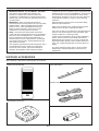
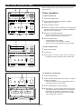
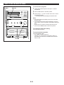
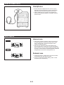
CC-5
Natural Sound Mini Component System
Active Servo Processing Speaker System
20 FM/10 AM Station Automatic Storing Capability
Double Cassette Tape Deck with Automatic Reverse Function
Tape “a” and “b” Continuous Playback Capability
Automatic Synchronized Recording with CD Playback
Automatic CD Editing Function for Recording to Tape
2-Way Speed Dubbing
Dolby B/C Noise Reduction System
3-Mode Sound Processor
Quick and Easy Direct Playback Function
Multi-Use Timer/Sleep Timer
Remote Control Capability
Thank you for selecting this YAMAHA mini component system.
This system is composed of TCD-CC5, A-CC5, K-CC5 and NS-CC5.
Active Servo
Technology
CAUTION
OWNER’S MANUAL
RISK OF ELECTRIC SHOCK
DO NOT OPEN
CONTENTS
Safety Instructions ..............Inside Front Cover
Supplied Accessories .............................. 1
Precautions ..............................................2
Active Servo Technology .........................3
Names of Controls, Indicators and Rear
Panel Parts ..........................................4–6
Remote Control Transmitter .................7–9
Preparation for Use ..........................10–11
Setting the Clock ....................................12
Compact Disc Operation ..................12–18
Tuner Operation ...............................19–21
Cassette Tape Operation .................22–24
Sound Control.........................................25
Recording .........................................26–30
How to Use the Built-in Timer...........31–33
Using External Units .........................34–35
Maintenance ...........................................35
Specifications .........................................36
Troubleshooting......................................37
CAUTION: TO REDUCE THE RISK OF
ELECTRIC SHOCK, DO NOT REMOVE
COVER (OR BACK), NO USER-SERVICEABLE
PARTS INSIDE, REFER SERVICING TO
QUALIFIED SERVICE PERSONNEL.
IMPORTANT!
Please record the serial number of this
unit in the space below.
• Explanation of Graphical Symbols
Model:
Serial No.:
The serial number is located on the rear
of the unit.
Retain this Owner’s Manual in a safe
place for future reference.
The lightning flash with arrowhead
symbol, within an equilateral triangle,
is intended to alert you to the
presence of uninsulated “dangerous
voltage” within the product’s
enclosure that may be of sufficient
magnitude to constitute a risk of
electric shock to persons.
WARNING
TO REDUCE THE RISK OF FIRE OR
ELECTRIC SHOCK, DO NOT EXPOSE
THIS UNIT TO RAIN OR MOISTURE.
The exclamation point within an
equilateral triangle is intended to alert
you to the presence of important
operating and maintenance
(servicing) instructions in the
literature accompanying the
appliance.
SAFETY INSTRUCTIONS
1
2
3
4
5
6
6A
7
8
9
10
11
12
13
14
15
A.
B.
C.
D.
E.
16
17
Read Instructions – All the safety and operating
instructions should be read before the unit is operated.
Retain Instructions – The safety and operating instructions
should be retained for future reference.
Heed Warnings – All warnings on the unit and in the
operating instructions should be adhered to.
Follow Instructions – All operating and other instructions
should be followed.
Water and Moisture – The unit should not be used near
water – for example, near a bathtub, washbowl, kitchen
sink, laundry tub, in a wet basement, or near a swimming
pool, etc.
Carts and Stands – The unit should be used only with a
cart or stand that is recommended by the manufacturer.
A unit and cart combination should
be moved with care. Quick stops,
excessive force, and uneven
surfaces may cause the unit and
cart combination to overturn.
Wall or Ceiling Mounting – The unit
should be mounted to a wall or ceiling only as
recommended by the manufacturer.
Ventilation – The unit should be situated so that its
location or position does not interfere with its proper
ventilation. For example, the unit should not be situated
on a bed, sofa, rug, or similar surface, that may block the
ventilation openings; or placed in a built-in installation,
such as a bookcase or cabinet that may impede the flow
of air through the ventilation openings.
Heat – The unit should be situated away from heat
sources such as radiators, stoves, or other appliances that
produce heat.
Power Sources – The unit should be connected to a power
supply only of the type described in the operating
instructions or as marked on the unit.
Power-Cord Protection – Power-supply cords should
be routed so that they are not likely to be walked on or
pinched by items placed upon or against them, paying
particular attention to cords at plugs, convenience
receptacles, and the point where they exit from the unit.
Cleaning – The unit should be cleaned only as
recommended by the manufacturer.
Nonuse Periods – The power cord of the unit should be
unplugged from the outlet when left unused for a long
period of time.
Object and Liquid Entry – Care should be taken so that
objects do not fall into and liquids are not spilled into the
inside of the unit.
Damage Requiring Service – The unit should be serviced
by qualified service personnel when:
The power-supply cord or the plug has been damaged;
or
Objects have fallen, or liquid has been spilled into the unit;
or
The unit has been exposed to rain; or
The unit does not appear to operate normally or exhibits a
marked change in performance; or
The unit has been dropped, or the cabinet damaged.
Servicing – The user should not attempt to service the unit
beyond those means described in the operating
instructions. All other servicing should be referred to
qualified service personnel.
Power Lines – An outdoor antenna should be located
away from power lines.
18 Grounding or Polarization – Precautions should be taken
so that the grounding or polarization is not defeated.
19 Outdoor Antenna Grounding – If an outside antenna is
connected to this unit, be sure the antenna system is
grounded so as to provide some protection against voltage
surges and built-up static charges. Article 810 of the
National Electrical Code, ANSI/NFPA 70, provides
information with regard to proper grounding of the mast
and supporting structure, grounding of the lead-in wire to
an antenna discharge unit, size of grounding conductors,
location of antenna discharge unit, connection to
grounding electrodes, and requirements for the grounding
electrode.
EXAMPLE OF ANTENNA GROUNDING
MAST
ANTENNA
LEAD IN
WIRE
GROUND
CLAMP
ANTENNA
DISCHARGE UNIT
(NEC SECTION 810–20)
ELECTRIC
SERVICE
EQUIPMENT
GROUNDING CONDUCTORS
(NEC SECTION 810–21)
GROUND CLAMPS
POWER SERVICE GROUNDING
ELECTRODE SYSTEM
(NEC ART 250. PART H)
NEC – NATIONAL ELECTRICAL CODE
Note to CATV system installer:
This reminder is provided to call the CATV system
installer's attention to Article 820-40 of the NEC that
provides guidelines for proper grounding and, in
particular, specifies that the cable ground shall be
connected to the grounding system of the building, as close
to the point of cable entry as practical.
We Want You Listening For A Lifetime
YAMAHA and the Electronic Industries Association’s
Consumer Electronics Group want you to get the most out of
your equipment by playing it at a safe level. One that lets the
sound come through loud and clear without annoying blaring
or distortion – and, most importantly, without affecting your
sensitive hearing. Since hearing damage from
loud sounds is often undetectable until it is too
late, YAMAHA and the Electronic Industries
Association’s Consumer Electronics Group
recommend you to avoid prolonged exposure
from excessive volume levels.
SPECIAL NOTES FOR FCC COMPOSITE DEVICE
This device is a composite system. The digital device
component may not cause harmful interference.
FCC INFORMATION
Compliance with FCC regulations does not guarantee that
interference will not occur in all installations. If this product
is found to be the source of interference, which can be
determined by turning the unit “OFF” and “ON”, please try
to eliminate the problem by using one of the following
measures:
1. IMPORTANT NOTICE : DO NOT MODIFY THIS UNIT!
This product, when installed as indicated in the
instructions contained in this manual, meets FCC
requirements. Modifications not expressly approved by
Yamaha may void your authority, granted by the FCC, to
use the product.
2. IMPORTANT : When connecting this product to
accessories and/or another product use only high quality
shielded cables. Cable/s supplied with this product
MUST be used. Follow all installation instructions.
Failure to follow instructions could void your FCC
authorization to use this product in the USA.
3. NOTE : This product has been tested and found to
comply with the requirements listed in FCC Regulations,
Part 15 for Class “B” digital devices. Compliance with
these requirements provides a reasonable level of
assurance that your use of this product in a residential
environment will not result in harmful interference with
other electronic devices.
This equipment generates/uses radio frequencies and, if
not installed and used according to the instructions
found in the users manual, may cause interference
harmful to the operation of other electronic devices.
Relocate either this product or the device that is being
affected by the interference.
Utilize power outlets that are on different branch (circuit
breaker or fuse) circuits or install AC line filter/s.
In the case of radio or TV interference, relocate/reorient the
antenna. If the antenna lead-in is 300 ohm ribbon lead,
change the lead-in to coaxial type cable.
If these corrective measures do not produce satisfactory
results, please contact the local retailer authorized to
distribute this type of product. If you can not locate the
appropriate retailer, please contact Yamaha Electronics
Corp., U.S.A. 6660 Orangethorpe Ave, Buena Park, CA
90620.
The above statements apply ONLY to those products
distributed by Yamaha Corporation of America or its
subsidiaries.
SUPPLIED ACCESSORIES
After unpacking, check that the following parts are contained.
Remote control transmitter
Indoor FM antenna
1
2
3
4
6
7
8
9
0
PROG
CLEAR
CALL
TIME
+10
BAND
TUNER
REPEAT
5
CD
b
Speaker cords
a
HALL
JAZZ CLUB
ROCK CNCT
POWER
AUX
DAT
OFF
-
TAPE
VOLUME
+
MW/LW(AM) loop antenna
Batteries (size AA, UM/SUM-3, R6, HP-7)
E-1
PRECAUTIONS: READ THIS BEFORE OPERATING YOUR UNIT
■ To assure the finest performance, please read this manual
carefully. Keep it in a safe place for future reference.
STANDBY mode
While the power is on, pressing the POWER switch (or the
POWER button on the remote control transmitter) switches the
unit to the STANDBY mode. (In this mode, the indicator above the
POWER switch illuminates.) In this mode, main voltage is still
present inside the unit. If you want to switch off the unit
completely, disconnect the AC power plug from the wall socket.
■ This unit is equipped with the newly developed Active Servo
Processing Speaker System. It is not designed for use with
conventional speakers. Therefore, do not attempt to connect
other speakers than the provided speaker system.
■ Choose the installation location of this unit carefully. Avoid placing
it in direct sunlight or close to a source of heat. Also avoid
locations subject to vibration and excessive dust, heat, cold or
moisture. Keep it away from sources of hum such as transformers
and electric motors.
NOTE
Please check the copyright laws in your country to record from
records, compact discs, radio, etc. Recording of copyright material
may infringe copyright laws.
■ Do not operate this unit upside-down. It may overheat, possibly
causing damage.
■ Never open the cabinet. If something drops into the set, contact
your dealer
If this unit’s operation freezes or display indications
are incorrect
First disconnect the AC supply lead from the wall AC outlet, and
then press the RESET button on the rear of this unit at least for
one minute. This operation “resets” the internal microcomputer
which controls this unit. However, this operation will also erase all
memorized broadcasting stations. To store stations again, follow
the methods described on page 19–20.
■ Do not place CD or other objects on top of this unit.
■ Do not use force on switches, controls or connection wires. When
moving the unit, first disconnect the power plug and the wires
connected to other equipment. Never pull the wire itself.
■ Do not attempt to clean the unit with chemical solvents; this might
damage the finish. Use a clean, dry cloth.
■ Be sure to read the “TROUBLESHOOTING” section regarding
common operating errors before concluding that the unit is faulty.
WARNING
■ To prevent lightning damage, disconnect the AC power plug and
disconnect the antenna cable when there is an electrical storm.
To reduce the risk of fire or electric shock, do not expose this unit to
rain or moisture.
■ Do not plug the AC power plug to the wall socket before you finish
all connections.
To avoid electrical shock, do not open the cabinet. Refer
servicing to qualified personnel only.
■ Never allow metallic items (e.g. screwdrivers, tools, etc.) to come
near the cassette deck’s record/playback head assembly in this
unit. Doing so may not only scratch or damage the head’s mirrorsmooth finish, it may change the magnetic characteristics of the
heads, causing a deterioration in reproduction performance
quality.
DANGER
Invisible laser radiation when open and interlock failed or
defeated. Avoid direct exposure to beam.
■ Although the cassette deck’s record/playback heads used in this
unit are high quality heads with outstanding reproduction
characteristics, they can become dirty through the use of old
tapes or from dust accumulation over time. This can have a
serious effect on reproduction quality. Clean the heads regularly
with one of the commonly available head cleaners or with
cleaning solutions.
CAUTION 1
Use of controls or adjustments or performance of procedures
other than those specified herein may result in hazardous
radiation exposure.
■ The voltage to be used must be the same as that specified on this
unit. Using this product with a higher voltage than that which is
specified is dangerous and may result in a fire or other type of
accident causing damage. YAMAHA will not be held responsible
for any damage resulting from use of this unit with a voltage other
than that which is specified.
CAUTION 2
As the laser beam used in this compact disc player is harmful to
the eyes, do not attempt to disassemble the cabinet. Refer
servicing to qualified personnel only.
■ Sudden temperature changes and storage or operation in an
extremely humid environment may cause condensation inside the
cabinet.
Condensation can cause the unit to malfunction.
Follow the procedure below to eliminate condensation.
•
•
•
Laser Diode Properties
Material: GaAlAs
Wavelength: 780nm
Emission Duration: continuous
Laser Output: max. 44.6µW*
* This output is the value measured at a distance of about 200mm
from the objective lens surface on the Optical Pick-up Block.
•
•
•
•
CD pickup
Leave the power on with no disc in the unit until normal
playback is possible (about 1 hour).
Tape head
Leave the power on with no cassette in the unit until normal
playback is possible (about 1 hour).
Note
If condensation forms on the tape head, foreign matter may
accumulate during use.
Remote control
Wipe off condensation on the transmitter window with a soft
cloth before operating the unit.
■ The sound level at a given volume setting depends on a
combination of speaker efficiency, location and may other factors.
Care should be taken to avoid exposure to sudden high levels of
sound, which may occur when turning on the unit with the volume
control setting at high, and to continuous high levels of sound.
E-2
ACTIVE SERVO TECHNOLOGY
Highamplitude
bass
sound
Cabinet
Air woofer
(Helmholtz resonator)
Port
Active Servo
Processing
Amplifier
Signals
Negative-impedance
output drive
Signals of low amplified
Thus it is this problem that is resolved through the
employment of a design in which the amplifier functions to
supply the signals. If the electrical resistance of the voice coil
is reduced to zero, the movement of the speaker unit would
become linear with respect to signal voltage, and, to
accomplish this, a special negative-impedance output-drive
amplifier for subtracting output impedance of the amplifier is
used.
By employing negative-impedance drive circuits, the amplifier
is able to generate precise, low-amplitude low-frequency
waves with superior damping characteristics, and these
waves are then radiated from the cabinet opening as highamplitude signals. The system can, therefore, by employing
the negative-impedance output drive amplifier and a speaker
cabinet with the Helmholtz resonator, reproduce an extremely
wide range of frequencies (28 Hz – 20 kHz) with amazing
sound quality and less distortion.
The features described above, then, are combined to be the
fundamental structure of the Active Servo Technology.
The theory of the Active Servo Technology is based upon two
major factors, the Helmholtz resonator and negativeimpedance drive. Active Servo Processing speakers
reproduce the bass frequencies through an “air woofer”,
which is a small port or opening in the speaker’s cabinet.
This opening is used instead of, and performs the functions
of, a woofer in a conventionally designed speaker system.
Thus, signals of low amplitude within the cabinet can,
according to the Helmholtz resonance theory, be output from
this opening as waves of great amplitude if the design is such
that the size of the opening and the volume of the cabinet are
in the correct proportion to satisfy a certain ratio.
In order to accomplish this, moreover, the amplitudes within
the cabinet must be both precise and of sufficient power
because these amplitudes must overcome the “load”
presented by the air that exists within the cabinet.
E-3
NAMES OF CONTROLS, INDICATORS AND REAR PANEL PARTS
CD Player Section
1 2
4
3
7 8
6
5
9
PROGRAM TOTAL REMAIN
TIME
OVER
AUTO
EDIT
RANDOM
A
9 10
8
2
3
6
1
4
5
7
11 12 13 14 15 16 17 18 19 20 OVER REPEAT
B
10
11
12 13 14
15
18
19
17
16
20 21
1.
2.
3.
4.
5.
6.
7.
8.
9.
10.
11.
12.
13.
14.
AUTO EDIT Indicator
TIME OVER Indicator
Track Number Indicator
PROGRAM Indicator
TOTAL Time Indicator
REMAINING Time Indicator
Minutes and Seconds Indicator
Pause Indicator:
Play Indicator:
Tape Side Indicators
Music Schedule Indicator
Music Schedule OVER Indicator
RANDOM Play Indicator
REPEAT Indicator
15.
16.
17.
18.
19.
20.
21.
22.
RANDOM Play Button
Stop Button:
Play Button:
Disc Table
Open/Close Button:
EDIT Button
Skip Buttons:
/
Auto Tape Edit Buttons
22
Tuner/Timer Section
23
25
24
MHz
kHz
MEMORY AUTO ST
STEREO
26
27
28 29
TIMER
SLEEP
ON TIME
30
31
32 33
35
36 37 38 39
40
34
41
E-4
23.
24.
25.
26.
27.
28.
29.
30.
31.
Preset Number Indicator
Band Indicator
Station Frequency Indicator
MEMORY Indicator
AUTO ST Indicator
FM STEREO Indicator
TIMER Set Indicator
ON TIME Indicator
SLEEP Indicator
32.
33.
34.
35.
36.
37.
38.
39.
40.
41.
AUTO MEMORY Button
BAND Selector Button
TUNER PRESET Buttons: /
DISPLAY Button
TIMER Button
SLEEP Button
MEMORY/TIME ADJUST Button
FM MODE/CLEAR Button
TUNING Down/HOUR Button:
TUNING Up/MINUTE Button:
NAMES OF CONTROLS, INDICATORS AND REAR PANEL PARTS
Amplifier Section
42
43
44
49
45
46
50
47
42.
43.
44.
45.
46.
47.
48.
49.
50.
POWER Switch
STANDBY Indicator
BASS Tone Control
TREBLE Tone Control
BALANCE Control
INPUT Selector and Indicators
VOLUME Control/Indicator
PHONES Jack
SOUND PROCESSOR Program Selector and
Indicators
51. Remote Control Sensor
48
51
Tape Deck Section
52
53 54 55 56 57 58 59 60 61 62 63 64
66
67
68 69 70
71
65
72
E-5
■
52.
53.
54.
55.
56.
57.
58.
Controls for Tape “a”
Tape “a” Cassette Compartment
EJECT Button
Fast Wind Button:
Play Button and Indicator:
Stop Button:
Play Button and Indicator:
Fast Wind Button:
■
59.
60.
61.
62.
63.
64.
65.
Controls for Tape “b”
Fast Wind Button:
Play Button and Indicator:
Stop Button:
Play Button and Indicator:
Fast Wind Button:
EJECT Button
Tape “b” Cassette Compartment
■
66.
67.
68.
69.
70.
71.
72.
Common Controls for Tape “a” and “b”
REVERSE MODE Switch
DOLBY NR Switch
DUBBING Buttons and Indicators
PAUSE Button
REC Button
Record Indicator
TIMER Switch
NAMES OF CONTROLS, INDICATORS AND REAR PANEL PARTS
Rear Panel of Tuner/CD Player Section
1.
2.
3.
4.
System Control Connector
Antenna Terminals
RESET Button
FREQUENCY STEP Switch (General model only)
FREQUENCY STEP switch (General model only)
Because the interstation frequency spacing differs in
different areas, set the FREQUENCY STEP switch
(located at the rear) according to the frequency spacing in
your area. Before setting this switch, disconnect the AC
supply lead of this unit from the AC outlet.
(U.S.A., Canada and General models)
Rear Panel of Amplifier Section
(U.K., Australia and Europe models)
5.
6.
7.
8.
9.
10.
11.
System Control Sockets
SPEAKERS Terminals
DAT Terminals
PHONO Terminals and GND Terminal
AUX Terminals
VOLTAGE SELECTOR (General model only)
AC Supply Lead
VOLTAGE SELECTOR (General model only)
The voltage selector on the rear panel of this unit must
be set for your local main voltage BEFORE plugging
into the AC main supply.
Voltages are 110/120/220/240V AC, 50/60 Hz.
Rear Panel of Tape Deck Section
12. System Control Connector
13. System Control Socket
Speaker Section
14. AST Port
15. Speaker Terminals
E-6
REMOTE CONTROL TRANSMITTER
Names of controls
1
1
2
3
4
5
6
7
8
9
0
PROG
CLEAR
CALL
TIME
+10
2
3
9
10
4
5
6
7
8
REPEAT
CD
BAND
TUNER
11
b
12
a
13
■
1.
2.
3.
4.
5.
6.
7.
8.
9.
10.
11.
12.
13.
14.
CD Control Buttons
Remote Control Transmitter Window
Track Number Input Buttons
PROGRAM Button
CLEAR Button
CALL Button
Search Buttons:
/
REPEAT Button
Stop Button:
TIME Display Selector Button
Open/Close Button:
Skip Buttons:
/
CD Call Button
Play Button:
Pause Button:
■
15.
16.
17.
Tuner Control Buttons
Tuning Up/Down Buttons
BAND Selector Button
TUNER Call Button
14
HALL
JAZZ CLUB
ROCK CNCT
POWER
AUX
DAT
15
OFF
-
TAPE
VOLUME
+
16 17
BAND
TUNER
OFF
TAPE
b
a
HALL
JAZZ CLUB
ROCK CNCT
POWER
AUX
DAT
-
VOLUME
+
E-7
REMOTE CONTROL TRANSMITTER
Tape “b”
■ Tape Control Buttons
18. Record/Pause Button:
19. Fast Wind Button:
20. Play Button:
21. Stop Button:
22. Play Button:
23. Fast Wind Button:
24. Fast Wind Button:
25. Play Button:
26. Stop Button:
27. Play Button:
28. Fast Wind Button:
29. TAPE Call Button
19 20 21 22 23
BAND
TUNER
OFF
TAPE
18
Tape “a”
b
a
28
24
HALL
JAZZ CLUB
ROCK CNCT
29
25 26 27
REPEAT
30. POWER Switch
31. AUX Call Button
32. DAT Call Button (or PHONO Call Button for U.K.,
Australia and Europe models)
33. Sound Processor Program Selectors
34. Sound Processor OFF Button
35. VOLUME Down (–)/Up (+) Buttons
CD
BAND
TUNER
b
33
a
HALL
JAZZ CLUB
ROCK CNCT
POWER
AUX
DAT
OFF
TAPE
34
30
-
VOLUME
+
35
31
32
E-8
REMOTE CONTROL TRANSMITTER
Loading the batteries for the remote control transmitter
1
2
Remove the battery compartment cover.
3
Replace the battery compartment cover.
Insert 2 “AA” size batteries (UM/SUM-3, R6, HP-7 or
equivalent) into the battery compartment.
* Placing the batteries the wrong way round will cause
malfunction.
Precautions for battery use
Insert the batteries according to the direction indicated in
the battery compartment.
Replace all batteries with new ones at the same time.
Remove the batteries if they are weak or if the unit is not
in use for long periods.
Don’t mix normal batteries with rechargeable batteries.
•
•
•
•
Proper use of the remote control
transmitter
Aim (within the range of 30° with no obstacles) the remote
control transmitter at the remote control sensor and operate
as shown.
Notes concerning use
• Replace the batteries if control distance decreases or
operation becomes unstable.
• Periodically clean the transmitter window on the remote
control transmitter and the sensor on the main unit with a
soft cloth.
• Exposing the sensor on the main unit to strong light
(especially an inverter type of fluorescent lamp etc.) may
interfere with operation. Change the lighting or the
direction of the unit.
• Keep the remote control transmitter away from moisture,
excessive heat, shock and vibrations.
• The remote control transmitter’s usable range is within
0.2m (8”) and 6m (20’) away from the sensor.
E-9
PREPARATION FOR USE
Placing the system
Tuner/CD player
A
Left speaker
Right speaker
Amplifier
B
Left speaker
Notes
• If the system is put in a rack, allow a space of a least 3 cm
(1-3/16”) above and 10 cm (4”) at the back of the unit.
• Disconnect the AC supply lead from the AC outlet before
connecting or disconnecting any component.
• Be careful not to let the connection cords touch the
radiator plates on the rear of the amplifier.
Deck
Tuner/CD player
Amplifier
Place this system in either the way of A or B figured at left.
A: Be sure to place the Tuner/CD player on the top, the Deck
at the bottom and the Amplifier between them.
B: Be sure to place the Tuner/CD player on the Deck, and
the Amplifier at the left of them.
Right speaker
Deck
Antenna connection
(1) Supplied FM antenna
Connect the FM antenna wire to the corresponding terminal
and direct the FM antenna wire to the direction where the
strongest signal can be received.
(2) Supplied MW/LW (AM) loop antenna
Connect the MW/LW (AM) loop antenna wire to the
corresponding terminals. Position the MW/LW (AM) loop
antenna for optimum reception. Place the MW/LW (AM) loop
antenna on a shelf etc., or install it on the rack or wall with
screws (not supplied).
15 m (49 feet)
Notes
• When static is still heard even after adjusting the position
of the MW/LW (AM) loop antenna, try reversing the
connection (right to left).
• Do not place the MW/LW (AM) loop antenna on the unit. It
will result in noise generation, since the unit is equipped
with digital electronics. Place the MW/LW (AM) loop
antenna away from the unit.
7.5 m (25 feet)
Earth rod
(3) External FM antenna
Use an external FM antenna instead of an indoor FM
antenna if you need better reception. Consult your dealer.
(4) External MW/LW (AM) antenna
Use an external MW/LW (AM) antenna if you need better
reception. Consult your dealer.
or
Note
When using an external MW/LW (AM) antenna, be sure to
keep the wire of the MW/LW (AM) loop antenna connected.
E-10
PREPARATION FOR USE
Speaker connection
Altavoz
derecho
Connect each speaker wire to the SPEAKERS terminals as
shown. (Black wire with white line → plus (+) terminal, black
wire → minus (–) terminal)
Altavoz
izquierdo
Cautions
• Do not let the bare speaker wires touch each other as this
could damage the amplifier and/or speakers.
• When connecting the speakers to the unit, be sure to
connect the speaker wires properly. Do not mistake the
right channel for the left channel and the plus (+) terminal
for the minus (–) terminal.
• Do not connect these SPEAKERS terminals to speakers
other than the provided speaker system.
System connection
•
•
•
Connect the red connector to the red socket.
Connect the white connector to the white socket.
Connect the black connector to the black socket.
How to disconnect the system connector
Grasp both sides of the connector to disconnect the
connector.
Connecting the AC supply lead
•
•
To an
AC outlet
E-11
After connecting the speakers and system connectors,
plug the AC supply lead into a convenient AC outlet.
Unplug the AC supply lead from the AC outlet if the unit is
not to be used for a long period of time.
SETTING THE CLOCK
1
1
While the station frequency indicator on the tuner or the
“ON TIME” indicator is lit, press the DISPLAY button to
display the time.
2
While pressing the TIME ADJUST button, press the
HOUR button and set the hour.
* Press the HOUR button once to advance the time by 1
hour. Press and hold to advance continuously.
3
While pressing the TIME ADJUST button, press the
MINUTE button and set the desired time.
* Press the MINUTE button once to advance the time by
1 minute. Press and hold to advance continuously.
* The hour setting will not advance even if minutes
advance from “59” to “00”.
4
Release the TIME ADJUST button to start the clock at the
correct time.
* The clock starts operating from “0” seconds. (Seconds
are not displayed.)
DISPLAY
2
TUNING
HOUR
MEMORY
MINUTE
FM MODE
Changes.
TIME ADJ
CLEAR
3
TUNING
HOUR
MEMORY
MINUTE
In the event of a power failure or when the AC supply
lead is disconnected.
The clock display will go out.
When the AC power supply is resumed, the clock display will
flash on and off to indicate that the time must be reset.
FM MODE
Changes.
TIME ADJ
CLEAR
4
TUNING
HOUR
MINUTE
MEMORY
FM MODE
TIME ADJ
CLEAR
Europe model uses an “00:00” 24-hour display.
COMPACT DISC OPERATION
Care of compact discs
Compact discs are fairly resistant to damage, however
mistracking can occur due to an accumulation of dirt on the
disc surface.
Follow the guidelines below for maximum enjoyment from
your CD collection and player.
• Do not write on either side of the disc, particularly the nonlabel side. Signals are read from the non-label side. Do
not mark this surface.
• Keep your discs away from direct sunlight, heat and
excessive moisture.
• Always hold the CDs by the edges. Fingerprints, dirt or
water on the CDs can cause noise or mistracking. If a CD
is dirty or does not play properly, clean it with a soft, dry
cloth, wiping straight out from the centre, along the radius.
E-12
COMPACT DISC OPERATION
CD playback
2,4
1
2
3
Select the CD position.
4
Press the open/close button to close the disc table.
* The total number of tracks and the total playing time
will be displayed for several seconds.
* The music schedule will be displayed only for the
number of tracks on the disc.
* If the compact disc contains more than 21 tracks, the
“OVER” indicator will light up on the music schedule.
5
Press the open/close button to open the disc table.
Place a disc on the table, label side up.
* 8 cm (3”) discs may be played without an adaptor.
Total number
of tracks
Remaining playing
time for first track
Total playing time
REMAIN
TOTAL
2
1
11 12
3
4
5
6
7
8
9
10
2
1
11 12
3
4
5
6
7
8
9
10
Music schedule
5
1
POWER
Press the play button to start playback from track 1.
* The “ ” indicator will appear and playback will begin.
As the playback of each track on the music schedule is
finished, that track number will go out.
Direct playback
1
1
2
3
4
5
6
7
8
9
0
PROG
CLEAR
CALL
TIME
+10
BAND
TUNER
OFF
TAPE
REPEAT
CD
b
a
POWER
HALL
JAZZ CLUB
ROCK CNCT
POWER
AUX
DAT
-
VOLUME
If a compact disc is already in the disc table, just press the
play button to automatically turn on the power and start
playback.
2,4
1
5,2
2
To interrupt playback
1
Press the pause button.
* The “ ” indicator will light up.
2
Press the play button to resume playback from the same
point.
+
To stop playback
Press the stop “
” button.
To switch the unit off after use
Set the unit to the STANDBY mode by pressing POWER
switch. (The indicators will go off except for the STANDBY
indicator and the current time display.)
E-13
COMPACT DISC OPERATION
Precautions
• If the disc is damaged, dirty or loaded upside down, the
display will show error signs as follows:
* “no disc” is displayed.
* The total track number or “01” is not displayed.
Clean, replace or load the disc properly.
• If TV or radio interference occurs during CD operation,
move the unit away from the TV or radio.
• Subjecting the unit to shock or vibration can cause
mistracking.
• Playing some compact discs at high volume can cause
mistracking. In this case, listen at lower volume.
• Do not push the disc table while it is moving.
• Press the open/close button if your finger, a disc or other
object is caught by the table. (The table closing operation
will stop after 4 seconds even if the open/close button is
not pressed. At this time, “Er 0:00” appears in the display.)
• If the power fails while the table is open, wait until the
power supply returns or gently push the table manually to
close it.
• The temperature range for playing compact discs is
recommended to be 5°C (41°F) – 35°C (95°F).
Direct-selection play
1
2
3
4
5
6
7
8
9
0
PROG
CLEAR
CALL
TIME
+10
1
2
3
4
5
6
7
8
9
0
By using the track number input buttons on the remote
control transmitter, any track you wish to listen to can be
played directly.
Use the track number input buttons to select the desired
track number. Play will begin automatically.
+10
REPEAT
A. For example, to choose selection 12
(1) Press the “+10” button.
(2) Within 3 seconds, press “2” button.
CD
BAND
TUNER
b
B. For example, to choose selection 20
(1) Press the “+10” button.
(2) Within 3 seconds, press the “+10” button again.
(3) Within 3 seconds, press the “0” button.
a
HALL
JAZZ CLUB
ROCK CNCT
POWER
AUX
DAT
OFF
-
TAPE
VOLUME
+
Note
A track number higher than the number of tracks on the disc
cannot be selected. Also, if a higher track number is selected
while the disc table is open, play will begin from track 1 when
the disc table is closed.
E-14
COMPACT DISC OPERATION
Skip search
2
The beginning of any track can be found automatically.
1
2
1
2
3
4
5
6
7
8
9
0
PROG
CLEAR
CALL
TIME
+10
REPEAT
1
CD
BAND
TUNER
OFF
TAPE
b
a
HALL
JAZZ CLUB
ROCK CNCT
POWER
AUX
DAT
-
VOLUME
Press the
button to forward or
button to reverse
through the CD.
* The “ ” indicator flashes while searching for the track
beginning.
* If the
button or
button is pressed repeatedly
during playback, playback will begin from the beginning
of the track shown in the track number indicator.
* This function can also be performed while the unit is
stopped. Press the play button when your desired track
number appears in the track number display. Playback
will begin from the beginning of the track.
Note
This function will be performed forward or backward from any
point on the disc. However, it will not move forward during
playback of the final track.
2
+
Load a disc and begin playback.
Manual search
1
2
1
2
3
4
5
6
7
8
9
0
PROG
CLEAR
CALL
TIME
+10
BAND
TUNER
OFF
TAPE
REPEAT
CD
b
a
HALL
JAZZ CLUB
ROCK CNCT
POWER
AUX
DAT
-
VOLUME
Begin playback.
Press and hold the
button to advance play rapidly,
and the
button to reverse play rapidly.
* The sound can be heard (although slightly garbled)
during manual search in either direction. This is
convenient for locating a precise position within a track,
or for reviewing the contents quickly.
* Manual search proceeds at twice the normal playback
speed for several seconds, and then the speed will
become faster.
Notes
• Manual search can also be performed while disc play is
paused.
• Manual search is not possible during random play.
• If the end of the disc is reached while searching, the “End”
indicator lights and CD operation is paused. Press the
stop button to stop CD operation.
+
E-15
COMPACT DISC OPERATION
Program play
You can program up to 20 tracks in any desired order.
2
1
2
3
4
5
6
7
8
9
0
PROG
CLEAR
CALL
TIME
+10
3
1
2
Load a disc and close the disc table.
3
Use the track number input buttons to select the desired
track number.
* The selected track number will be displayed.
* The programmed playback order and the total play
time of the programmed tracks will be automatically
displayed, and only those track numbers will appear in
the music schedule.
5
REPEAT
When in the stop mode, press the PROGRAM button to
prepare for programming.
* The “PROGRAM” indicator will flash.
CD
BAND
TUNER
OFF
TAPE
b
a
HALL
JAZZ CLUB
ROCK CNCT
POWER
AUX
DAT
-
+
VOLUME
* For example, to choose selection 12
(1) Press the “+10” button.
(2) Within 3 seconds, press the “2” button.
Playback order
PROGRAM
2
12
1
4
Repeat step 3 for any other track. Up to 20 tracks can be
programmed.
5
Press the play button to start playback of programmed
selections.
Total playing time
TOTAL
Notes
It is also possible to program a sequence of tracks while
looking at the list of tracks on the surface of the disc
before closing the disc table.
• During playback or pause, programming is not possible.
10
3
•
Music schedule
To check the program data
1
2
3
4
6
7
8
9
0
PROG
CLEAR
CALL
TIME
+10
REPEAT
Press the CALL button while the disc is stopped to review the
order of the programmed sequence before playback begins.
* While the playback order and track numbers are
displayed, the track numbers on the music schedule will
also flash on and off in the same order.
5
CALL
Press the CALL button during playback or pause to check the
number of the next track to be played.
CD
BAND
TUNER
CLEAR
b
To cancel the programmed sequence
a
HALL
JAZZ CLUB
ROCK CNCT
POWER
AUX
DAT
OFF
-
Press the CLEAR button while the disc is stopped and the
“PROGRAM” indicator is lit.
* To cancel the last programmed track during programming,
press the CLEAR button when the “PROGRAM” indicator
is flashing.
TAPE
VOLUME
+
Notes
• Opening the disc table automatically cancels the
programmed sequence.
• Programming and cancelling are not possible during
playback or pause.
Playback order
PROGRAM
1
2
12
Track number
TOTAL
3
10
Music schedule
E-16
COMPACT DISC OPERATION
Repeat play
An entire disc, a single track or a programmed sequence can
be continuously repeated.
To repeat an entire disc
1
2
3
4
5
6
7
8
9
0
PROG
CLEAR
CALL
TIME
+10
2,3
3
1,2
2
REPEAT
1
Press the REPEAT button.
* The “REPEAT” indicator will light up.
2
Press the play button.
CD
BAND
TUNER
OFF
TAPE
To repeat a programmed sequence
b
a
HALL
JAZZ CLUB
ROCK CNCT
POWER
AUX
DAT
-
VOLUME
1
Program a sequence of up to 20 tracks.
(Refer to the “Program play” on the previous page for the
programming method.)
2
Press the REPEAT button.
* The “REPEAT” indicator will light up.
3
Press the play button.
+
To repeat a single track
2
1
11 12
3
4
5
6
7
8
9
1
Program a single track.
(Refer to the “Program play” on the previous page for the
programming method.)
2
Press the REPEAT button.
* The “REPEAT” indicator will light up.
3
Press the play button.
10
REPEAT
To cancel the repeat play
Press the REPEAT button again.
(The “REPEAT” indicator goes out.)
E-17
COMPACT DISC OPERATION
Random play
The tracks on the disc can be played in a random order.
1
2
RANDOM
3
1
2
Load a disc and close the disc table.
Press the RANDOM button to begin random play.
* The “RANDOM” indicator will light up.
* As the tracks to be played are selected, the track
numbers “[1]”, “[2]”, “[3]” ... “[20]” in the music schedule
will flash on and off and the track number display will
change accordingly.
To cancel the random play
Press the play button. The “RANDOM” indicator goes out.
Notes
• When using random play or repeat play, be sure to press
the stop button, or switch off the power when you have
finished listening. Otherwise, the CD(s) will be played
endlessly.
• While programmed tracks are being played, random play
is not possible.
Switching the time display
Each time the TIME button is pressed, the display will
change as described below.
TIME
2
3
4
5
6
7
8
9
0
PROG
CLEAR
CALL
TIME
+10
REPEAT
[Example]
When the second track is being played back. (Refer to the
illustration on the left.)
➀
1
2
11 12
3
4
5
6
7
8
9
10
➀ The elapsed play time for each track will be displayed.
CD
BAND
TUNER
2
11 12
b
➁
REMAIN
➁
3
4
5
6
7
8
9
10
a
HALL
JAZZ CLUB
ROCK CNCT
POWER
AUX
DAT
OFF
-
➂
TAPE
VOLUME
+
TOTAL
➂
2
11 12
3
4
5
6
7
8
9
10
➃
* 8 seconds have passed since the beginning of the
second track.
The remaining play time for the current track will be
displayed.
* 2 minutes and 58 seconds remain till the end of the
second track.
The total play time up to the current track will be
displayed.
* 8 minutes and 16 seconds have passed since the
beginning of the first track.
The total remaining play time from the point being played
at that time will be displayed.
* 41 minutes remain till the end of the disc.
TOTAL REMAIN
➃
2
11 12
3
4
5
6
7
8
9
Notes
During random play, the elapsed play time for each track
will be displayed, and the display cannot be switched.
When a disc that has 21 or more tracks is used, “--:--” will
be displayed in the following cases:
* When an attempt is made to display a track number 21
or higher by using the
button when the disc is
stopped.
* When an attempt is made to display the remaining time
while a track whose number is 21 or higher is being
played back.
* When you program a track number 21 or higher .
* When the total play time exceeds 100 minutes.
10
•
•
E-18
TUNER OPERATION
You can store up to 30 stations (20 FM stations and 10 AM
(LW or MW) stations) and recall them together with their FM
reception mode (stereo or mono), at the push of a button.
2
3
Auto scan memory
By this method, the unit will store stations with strong signals
automatically (for FM and AM (LW or MW) respectively).
1
1
2
3
4
6
7
8
9
0
PROG
CLEAR
CALL
TIME
+10
BAND
TUNER
OFF
TAPE
REPEAT
CD
a
1
2
HALL
JAZZ CLUB
ROCK CNCT
POWER
AUX
DAT
-
VOLUME
Select the TUNER position.
3
Press the AUTO MEMO button.
* The “MEMORY” indicator will flash.
* After auto scan memory is finished, the “MEMORY”
indicator goes out, and you can hear the broadcast
station which was stored last into memory.
* If fewer than 20 FM stations or 10 AM (LW or MW)
stations have been stored in memory, auto scan
memory will stop at the highest frequency and this unit
will turn into receiving mode.
* If auto scan memory is performed again though
broadcasting stations have been already stored, the
previous contents are erased.
Select the desired frequency band. [FM or AM (LW or
MW)]
Note
The auto scan memory function may be affected by radio
interference generated by electric equipment. For example,
home computers, facsimiles, etc.
If you have difficulty using the auto scan memory, move the
unit away from electric equipment and adjust the position of
the antenna to minimize the interference. If you cannot
minimize the interference, please use the manual memory
function as described below.
5
b
1
2
+
“AM” is for U.S.A., Canada, Australia and General
models.
“MW/LW” is for U.K. and Europe models.
E-19
TUNER OPERATION
Manual memory
3,5
When auto scan memory does not function due to a weak
signal, frequencies are deviated due to a strong signal, or
you want to change the memory contents, perform the
following operation.
2 4
1
2
Perform steps 1 – 2 of the “Auto scan memory” section.
Use the TUNING (
desired station.
or
) button to tune into the
Auto tuning
When the TUNING (
or
) button is pressed for more
than 0.5 second and then released, the tuning stops at the
first receivable broadcast station.
Manual tuning
Press the TUNING (
or
) button repeatedly to adjust
the frequency display to the frequency of the desired
station.
E-20
3
Press the MEMORY button, so that the display’s
“MEMORY” indicator flashes.
4
Press the TUNER PRESET (
or
) button until the
preset number to be programmed appears in the display.
5
Press the MEMORY button to store that station in the
selected station preset number memory.
* 20 FM stations can be preset (preset channels 1
through 20).
* 10 AM (LW or MW) stations can be preset (preset
channels 1 through 10).
(There are no presets 11 through 20 for AM (LW or
MW) stations.)
6
Repeat steps 1 – 5 to set the other preset stations, or to
change a preset station.
TUNER OPERATION
2
4
To recall a memorized station
3
1
2
Select the TUNER position.
3
Press the TUNER PRESET (
or
) button to recall
the desired preset station number. The caption FM or AM
(LW or MW) and a frequency will appear in the display.
4
To set to FM stereo mode, press the FM MODE button so
that the “STEREO” indicator on the display lights up. If the
reception is poor, press the FM MODE button so that the
“STEREO” indicator goes out.
* The “AUTO ST” indicator lights up when an FM
broadcast is in stereo.
* Please note that when the unit is being tuned in the FM
stereo mode, interim station noise as well as weak
stations are suppressed. Only in the FM monaural
mode, weak and noisy stations can be received.
1
Select the desired frequency band. [FM or AM (LW or
MW)]
To switch the unit off after use
1
2
3
4
Set the unit to the STANDBY mode by pressing the POWER
switch. (The indicators will go off except for the STANDBY
indicator and the current time display.)
5
6
7
8
9
0
PROG
CLEAR
CALL
TIME
+10
3
REPEAT
Notes
• Memory recalls the last station received even after
changing the BAND selector button or setting the unit to
the STANDBY mode.
• After a power failure that lasts for some time, the contents
of the memory will be lost. When power is restored, store
your selections in memory again.
(For power failures of just a few hours, the contents of the
memory will not be lost.)
CD
BAND
TUNER
OFF
TAPE
b
a
HALL
JAZZ CLUB
ROCK CNCT
POWER
AUX
DAT
-
VOLUME
1
2
+
To clear all memorized stations
To clear all the memory contents or when the display is
incorrect:
3
1
2
3
E-21
Set the unit to the STANDBY mode.
Disconnect the AC supply lead from the AC outlet.
Press the RESET button for at least 60 seconds.
CASSETTE TAPE OPERATION
General information
•
•
•
•
•
•
•
Detection hole
Tab
•
Do not use C-120 tapes, tapes with internal reels or poorquality tapes, since they can cause malfunctions.
Before loading a tape into the cassette compartment,
tighten the slack tape with a pen or pencil.
Tapes have removable tabs which prevent accidental
recording or erasing from taking place. Removing the tab
on the top left protects the side facing you from erasure.
Cover the tab holes with adhesive tape to erase or record
again.
This deck is a Double Cassette Deck with Automatic
Reverse Function.
Tape “a”: Playback only.
Tape “b”: Playback or recording.
This deck features an auto tape selector. Just load the
tape, and the tape formula being used will be sensed
automatically.
This unit can playback metal tapes as well as normal or
chrome tapes, however recording cannot be done on
metal tapes only.
When covering erasure prevention tab holes, do not cover
the chrome and metal detection holes. Otherwise, the
deck will treat tape as normal tape.
Do not press the EJECT button during playback or
recording.
Tape “a” or tape “b” playback
1
3
3
1
2
Select the TAPE position.
3
Load the cassette into the tape “a” or tape “b” cassette
compartment.
4
Set the DOLBY NR switch to B or C if the tape has been
recorded with Dolby noise reduction, and to OFF if Dolby
NR was not used.
* For selection of the Dolby B or C position, refer to the
“Dolby B and C Type Noise Reduction” on page 24.
5
Set the REVERSE MODE switch as desired.
(b)
(a)
4
Open the tape “a” or tape “b” cassette compartment by
pushing the EJECT button.
The REVERSE MODE switch can be operated before or
during playback, and changes tape playback as follows:
2(a) 5 6(a)
6(b)
2(b)
6
E-22
Side A only
Side A → Side Side A → Side B
Continuous play
B
Side B only
Side B only
Side B → Side A
Continuous play
Press the play
button to listen to side A, or the
play
button for side B.
CASSETTE TAPE OPERATION
Direct playback
If a cassette tape is already in the cassette compartment, just
press the play button to automatically turn on the power and
start playback.
Note
While the INPUT selector is rotating to select the TAPE
position before playback starts, do not press the EJECT
button.
To stop playback
Press the stop
button.
Note
When removing the cassette tape, press the stop
and then open the cassette compartment.
button,
To switch the unit off after use
Set the unit to the STANDBY mode by pressing the POWER
switch. (The indicators will go off except for the STANDBY
indicator and the current time display.)
Winding the tape
1
2
3
First press the stop
button.
Next press the
or
button to wind the tape.
Press the stop
button to stop.
Searching for the beginning of a
desired selection
(a)
Carry out the following operation during playback to find the
beginning of a desired selection on the tape.
(b)
•
•
1
2
3
4
6
7
8
9
0
TIME
+10
BAND
TUNER
PROG
CLEAR
CALL
REPEAT
5
Notes
This function may not work for tapes with
• Material with long pauses or quiet passages.
• Low recording levels or excessive noise.
• Pauses of less than 3 seconds between selections.
CD
(b)
b
a
HALL
JAZZ CLUB
ROCK CNCT
POWER
AUX
DAT
OFF
-
TAPE
VOLUME
To listen to the same selection, press the
or
button in the direction opposite from that of current
playback.
To listen to the next selection, press the
or
button
in the same direction as that of current playback.
+
(a)
E-23
CASSETTE TAPE OPERATION
Continuous playback
1
1
Load the tapes into the tape “a” and tape “b” cassette
compartments.
2
Set the REVERSE MODE switch as desired.
The REVERSE MODE switch can be operated before or
during playback, and changes tape playback as follows:
2 3(a)
3(b)
Tape “a” Side A → B
→ Tape “b” Side A →
B
Tape “a” Side A → B
→ Tape “b” Side A
→B
Continuous play
Tape “a” Side B →
Tape “b” Side A → B
Tape “a” Side B →
Tape “b” Side A → B
→ Tape “a” Side A
Continuous play
<Tape “a”>
<Tape “a”>
1
2
3
4
6
7
8
9
0
PROG
CLEAR
CALL
TIME
+10
BAND
TUNER
OFF
TAPE
REPEAT
5
3
CD
Press the play
button to listen to side A, or the
play
button for side B.
3(b)
b
a
3(a)
HALL
JAZZ CLUB
ROCK CNCT
POWER
AUX
DAT
-
VOLUME
+
Dolby B and C Type Noise Reduction
With cassette tapes, the most noticeable form of noise is high
frequency hiss. To reduce this hiss noise, this unit has been
equipped with a newly developed Dolby C noise reduction
system in addition to its conventional Dolby B NR. Either type
of noise reduction may be selected with the switch provided.
Dolby B NR has a noise reduction effect of about 10 dB in
the high frequency range. The corresponding figure with
Dolby C NR is about 20 dB, but this is over the entire range
where the human ear is most sensitive to noise (2 kHz to 8
kHz). Also, Dolby C NR has the same noise reduction effect
at both high and low signal levels. In addition, Dolby C NR
improves the tape’s MOL (Maximum Output Level).
Dolby noise reduction is a 2 part process that acts both on
recording and playback; be sure that the noise reduction
button is set to the same position on record and play.
* Noise in the source material cannot be reduced with the
Dolby NR system.
Dolby and the double D mark are trademarks of Dolby
Laboratories Licensing Corp. Dolby noise reduction
system manufactured under license from Dolby
Laboratories Licensing Corp.
E-24
SOUND CONTROL
Volume
VOLUME
Front panel operation
Rotate the VOLUME control towards 10 to increase the
volume, and towards 0 to decrease the volume.
5
4
6
3
7
-
VOLUME
+
Remote control operation
Press the VOLUME + button to increase the volume and the
VOLUME – button to decrease the volume.
8
2
I
9
0
10
Balance
BALANCE
Adjust the balance of the output volume to the left and right
speakers to compensate for sound imbalance caused from
the speaker settings or the listening room condition.
Turn this clockwise to emphasize the right and
counterclockwise for the left.
L
R
Tone
TREBLE
BASS
BASS
TREBLE
-
+
-
+
: Turn this clockwise to increase (or counterclockwise to decrease) the low frequency
response.
: Turn this clockwise to increase (or counterclockwise to decrease) the high frequency
response.
Sound processor
SOUND PROCESSOR
JAZZ
ROCK
CLUB
CONCERT
If desired, select your favorite sound processor program by
pressing the SOUND PROCESSOR button. The indicator
below the name of the selected program illuminates. (No
illumination shows that the sound processor is off.) For each
program feature, refer to the following explanation.
HALL
HALL
The ideal program for listening to opera or
orchestra music. This program creates an
expansive, large hall ambience. The
apparent listening position is in the center of
the hall rather than in front of the stage.
JAZZ
CLUB
This program creates an ambience of
intimate jazz club with a low ceiling and a
stage located in a corner. You feel so close
to music by this program.
ROCK
CONCERT
E-25
This program suits to rock music. A big,
powerful sound is reproduced lively and
dynamically.
RECORDING
•
•
•
When recording important selections, be sure to make a
preliminary test to ensure that the desired material is
being properly recorded.
The automatic recording level control circuit automatically
controls the level of the input signal used for recording.
Adjusting the VOLUME, BALANCE, TREBLE and BASS
controls and selecting any SOUND PROCESSOR
program have no effect on the recorded sound.
Recording from the CD player (CD
Synchronized Recording System)
1
6,2
2
1
2
Select the CD position and load the CD to be recorded.
3
When recording with the Dolby NR system, set the
DOLBY NR switch to B or C; if not, set it to OFF.
* For selection of the Dolby B or C position, refer to the
“Dolby B and C Type Noise Reduction” on page 24.
4
Set the REVERSE MODE switch to
to record on only
one side, or to
for continuous recording on both sides.
5
Press the REC button.
* The indicator next to the REC button will light up and
the play indicator flash.
6
Press the play button of the CD.
* Before CD playback begins, recording automatically
begins on side A of the tape.
Load a tape into the tape “b” cassette compartment.
* Wind past the beginning part of the tape on which
recording can not be performed.
To stop recording temporarily
1
2
4
3
5
2
Press the pause button of the CD.
Press the play button of the CD to resume recording.
To stop recording
Press the stop
button of the tape deck.
(At this time, CD playback does not stop.)
1
2
3
4
6
7
8
9
0
PROG
CLEAR
CALL
TIME
+10
REPEAT
5
5
CD
BAND
TUNER
OFF
TAPE
1
1
b
a
6,2
2
HALL
JAZZ CLUB
ROCK CNCT
POWER
AUX
DAT
-
VOLUME
+
E-26
RECORDING
To exchange a CD for another CD while recording
2
1
Press the stop button of the CD during recording.
* The tape stops after about 2 seconds and enters
recording standby mode.
2
3
Replace the CD.
4
Press the play button of the CD.
* Recording begins after about 2 seconds.
1
4
Choose the selection to be recorded next by using the
or
button.
Note
The CD Synchronised Recording System will function even
when the CD player is set to the program play or random
play mode. In this case, when more than 2 seconds elapse
between tracks, the tape will stop automatically and resume
recording when the beginning of the next track is found.
3
3
When recording is continuously made on both
sides of the tape
1
2
3
4
Even if the recording for side A is finished halfway through a
track, side B will automatically start recording from the
beginning of that track. (Auto restart function)
So recording for side B will be made without cutting the
beginning of a track.
5
6
7
8
9
0
PROG
CLEAR
CALL
TIME
+10
4
1
REPEAT
CD
BAND
TUNER
OFF
TAPE
b
a
HALL
JAZZ CLUB
ROCK CNCT
POWER
AUX
DAT
-
VOLUME
+
E-27
RECORDING
1
7
To edit tracks dividing them to
side A and side B automatically
(Auto editing function)
8
To use tapes effectively, tracks on a CD are automatically
rearranged between side A and side B to best utilize the
length of the tape.
When the desired tracks are selected in program selection,
the tracks stored in memory are automatically divided
between side A and side B.
6
4
3
5
1
2
Select the CD position and load the CD to be recorded.
3
When recording with the Dolby NR system, set the
DOLBY NR switch to B or C; if not, set it to OFF.
* For selection of the Dolby B or C position, refer to the
“Dolby B and C Type Noise Reduction” on page 24.
4
5
Set the REVERSE MODE switch to
6
Press the C46, C60 or C90 according as the length of the
tape to be used.
2
Load a tape into the tape “b” cassette compartment.
* Rewind the tape onto the left-side reel.
.
Press the REC button.
* The indicator beside the REC button lights up and the
play indicators flash.
When using tapes other than C46, C60 or C90
Press the
or
button to adjust the time (minute by
minute).
• Adjustable range is from C10 to C99.
1
2
3
4
6
7
8
9
0
PROG
CLEAR
CALL
TIME
+10
REPEAT
5
5
CD
BAND
It is also possible to use the track number input buttons on
the remote control to set the tape length.
• For a tape length of C30, press the “+10”, “+10”, “+10”
and “0”. (Press each button within 3 seconds after the
previous one has been pressed.)
TUNER
b
7
Press the EDIT button.
* Tracks on the CD are automatically divided between
side A and side B.
* The number of tracks, total time and track numbers to
be recorded on side A and side B are displayed for
approximately 4 seconds. (When there are tracks
which can not be recorded, the “TIME OVER” indicator
will light up.)
8
Press the play button of the CD.
* CD playback and recording start approximately 9
seconds after the tape starts (after the part of the tape
on which recording can not be performed is wound).
1
8
a
HALL
JAZZ CLUB
ROCK CNCT
POWER
AUX
DAT
OFF
-
TAPE
VOLUME
+
To cancel auto editing function
Before recording, press the stop
button of the CD.
To stop recording
Press the stop
button of the tape.
(At this time, CD playback automatically stops.)
E-28
RECORDING
To confirm tracks to be recorded and tracks which
can not be recorded
1
2
3
4
5
6
7
8
9
0
PROG
CLEAR
CALL
TIME
+10
REPEAT
Before recording, press the TIME button. The following
information will appear on the display by turns whenever the
TIME button is pressed.
TIME
→
Tracks to be recorded on side A
↓
CD
BAND
Tracks to be recorded on side B
↓
TUNER
b
Tracks which can not be recorded on side A and side
B (When all tracks can be recorded, “00 0:00” is
displayed)
a
HALL
JAZZ CLUB
ROCK CNCT
POWER
AUX
DAT
OFF
-
↓
TAPE
VOLUME
+
Tracks which can be recorded on side A and side B
Note
Once CD playback starts, the display does not change.
Dubbing
2
•
1
•
3
During dubbing, adjusting the VOLUME, BALANCE,
TREBLE and BASS controls and selecting any sound
processor program have no effect on the recorded sound.
Try to use the same tape formula and length for the
recording tape as for the master tape.
1
2
Select the TAPE position.
3
Set the REVERSE MODE switch to
to record on only
one side, or to
for continuous recording on both sides.
4
Press the DUBBING button.
* Press “NORMAL” to dub at normal speed, and “HIGH”
to dub at about twice the normal speed.
* Dubbing will begin from side A.
Load a prerecorded tape into the tape “a” cassette
compartment. Insert a blank tape into the tape “b”
cassette compartment.
To stop dubbing
4
Press the stop
button for tape “a” or “b”.
* Tape “a” and tape “b” will stop at the same time.
Note
Only tapes originally encoded with Dolby B or C NR will be
dubbed onto tapes with Dolby B or C NR encoding.
The DOLBY NR switch will have no effect on the recording of
tape “b” during dubbing.
However, the playback tonal quality of tape “a” will change
according to the DOLBY NR switch position.
E-29
RECORDING
Recording from the built-in tuner
2
4
3
1 5
1
2
3
4
6
7
8
9
0
PROG
CLEAR
CALL
TIME
+10
REPEAT
5,1
1
6
1
Tune to the desired station. (Refer to the “TUNER
OPERATION” on page 19.)
2
3
Load a tape into the tape “b” cassette compartment.
4
Set the REVERSE MODE switch to
to record on only
one side, or to
for continuous recording on both sides.
5
Press the REC button.
* The indicator beside the REC button lights up and the
play indicators flash.
6
Press the play
button to record side A, or the play
button to record side B.
* For continuous recording of both sides, begin on side
A. Recording stops automatically at the end of side B.
5
CD
BAND
TUNER
OFF
TAPE
When recording with the Dolby NR system, set the
DOLBY NR switch to B or C; if not, set it to OFF.
* For selection of the Dolby B or C position, refer to the
“Dolby B and C Type Noise Reduction” on page 24.
To stop recording temporarily
6,2
2
1
2
b
Press the PAUSE button.
To resume recording, press the play button whose
indicator is flashing.
a
HALL
JAZZ CLUB
ROCK CNCT
POWER
AUX
DAT
-
VOLUME
To stop recording
Press the stop
+
button.
Erasing recorded tapes
E-30
1
Load the tape to be erased into the tape “b” cassette
compartment.
2
3
Select the AUX position with the INPUT selector.
4
Press the REC button, then press the play
button to
erase side A of tape, or the play
button to erase side B.
Set the REVERSE MODE switch to
side and to
to erase both sides.
to erase only one
HOW TO USE THE BUILT-IN TIMER
6
5
Before setting the timer clock, make sure that the current
time is correct.
4
Timer operation
To listen to the tuner
1
2
Select the TUNER position.
3
4
Press the DISPLAY button.
5
Release the TIME ADJUST button.
* When the start time of the timer is set by mistake,
press the CLEAR button and repeat step 4.
6
Press the TIMER button.
* “TIMER” appears on the display.
This sets the timer to the stand-by condition.
* The tuner turns on automatically at the desired time.
3
1
CLEAR
2
1
Tune to the desired station. (Refer to the “TUNER
OPERATION” on page 19.)
While the “TIMER” indicator is flashing, and while pressing
the TIME ADJUST button, press the HOUR and MINUTE
buttons to set the desired time.
To play a compact disc
1
2
3
2
Select the CD position.
Load the disc.
Perform steps 3 – 6 of the “To listen to the tuner” section.
* CD playback starts automatically at the desired time.
To playback a cassette tape
1
3
E-31
1
2
Select the TAPE position.
3
4
Set the TIMER switch to the PLAY position.
Load a recorded cassette tape into the tape “a” or tape “b”
cassette compartment.
* If tapes are loaded in both the compartments, tape “b”
will be played back by the timer play.
Perform steps 3 – 6 of the “To listen to the tuner” section.
* Tape playback starts automatically at the desired time.
(Playback of the side which corresponds to the play
button which illuminated just before the timer setting
was completed will commence.)
HOW TO USE THE BUILT-IN TIMER
To record tuner programs
POWER
DISPLAY
1
Load a blank cassette tape into the tape “b” cassette
compartment.
2
3
Set the TIMER switch to the REC position.
Perform steps 1 – 5 of the “To listen to the tuner” section
on the previous page.
* Recording starts automatically at the desired time.
Notes
The power will be automatically turned off 2 hours after
the timer starts.
To set the desired volume level for listening to a source
with the timer, use the VOLUME control before setting the
timer.
• Except when you perform recording with the timer, be
sure to set the TIMER switch to the PLAY position.
•
•
To confirm the timer time setting
Press the DISPLAY button.
To cancel the timer operation
VOLUME
2
Press the POWER switch.
* The “TIMER” indicator will go out.
* Unless the AC supply lead is unplugged or there is a
power failure, the time set on the timer will be retained
until it is reset.
1
E-32
HOW TO USE THE BUILT-IN TIMER
Sleep timer operation
SLEEP
This unit can be turned off automatically.
Play the desired sound source.
Press the SLEEP button repeatedly until the desired sleep
time appears in the display. The display will change as
described below. (Time is displayed by the minute.)
30
↑
45
Current Time
↑
↑
60
↑
↑
1
2
15
* The original display mode will resume about 5 seconds
after the selection is made.
* If the current time is selected, the power is turned off
after 2 seconds.
3
The unit will turn off automatically after the preset sleep
time.
To confirm the sleep time setting
Press the SLEEP button once. The remaining time of the
preset sleep time appears in the display.
To change the sleep time
↑
15
↑
Current time
30
↑
↑
Remaining time of
the preset sleep time
60
↑
While the “SLEEP” indicator is on, press the SLEEP button
repeatedly until the desired time to replace appears. The
display will change as described below.
45
↑
POWER
* If the current time is selected, the power is turned off
after 2 seconds.
To stop the sleep timer operation
Press the POWER switch.
(The “SLEEP” indicator will go out.)
Using the timer and the sleep
timer at the same time
1
2
Prepare timer playback. (See page 31.)
Press the SLEEP button and set the sleep time.
* When the sleep timer operation finishes, the timer will
function to turn the source on at the preset time.
Notes
* The source set in the sleep timer operation will be turned
on at the time set in the timer playback operation.
* Do not set the timer time so that the timer will start during
sleep timer operation. (Since sleep timer operation has
priority, the timer will not operate.)
E-33
USING EXTERNAL UNITS
Auxiliary (AUX)
1
Connect the output lead of a video cassette player, video
disc player, etc. to the AUX inputs of this unit.
(red → right channel, white → left channel)
2
3
4
Select the AUX position with the INPUT selector.
Operate the unit connected to the AUX inputs.
Start recording with this unit, if so desired. (See page 30.)
Auxiliary (DAT) (U.S.A., Canada
and General models)
1
Connect the output lead of a DAT or another input source.
(red → right channel, white → left channel)
2
3
4
Select the DAT position with the INPUT selector.
Operate the unit connected to the DAT inputs.
Start recording with this unit, if so desired.
(See page 30.)
Turntable (PHONO) (U.K., Australia
and Europe models)
E-34
1
Connect the output lead of a turntable.
(red → right channel, white → left channel)
2
3
4
5
Connect the GND lead of a turntable.
Select the PHONO position with the INPUT selector.
Operate the turntable.
Start recording with this unit, if so desired. (See page 30.)
USING EXTERNAL UNITS
Headphones
•
•
Be sure that your headphones have a 3.5 mm (1/8”)
diameter plug and are between 16 ohms and 50 ohms
impedance. Recommended impedance is 32 ohms.
When headphones are connected, the speakers are
defeated automatically. Adjust the VOLUME control for
desired volume.
MAINTENANCE
Internal care
Tape “a”
•
•
Tape “b”
Dirty heads, capstans and pinch rollers can cause poor
sound and tape jams. Clean these parts with a cotton
swab moistened with commercial head/pinch roller
cleaner or isopropyl alcohol.
After long use, the deck’s heads and capstans may
become magnetised, causing poor sound. Demagnetise
these parts once every 30 hours of playing/recording time
by using a commercial tape head demagnetiser. Read the
demagnetiser’s instructions carefully before use.
External care
•
•
E-35
Periodically wipe the cabinet with a soft cloth and dilute
soap solution, then wipe with a dry cloth.
Do not use chemically treated cleaning cloths or other
chemicals. (See “Precautions”.)
SPECIFICATIONS
As a part of policy of continuous improvement, YAMAHA reserves the right to make design and specification changes for
product improvement without prior notice. The performance specification figures indicated are nominal values of production
units.
■ Tuner/CD player section
■ Amplifier section
Power source .................................. AC supplies from amplifier unit
Input sensitivity and input impedance ..... AUX; 200 mV/47 kohms
Load impedance .................................. Headphones; 16 – 50 ohms
(recommended; 32 ohms)
Dimensions ............................................... Width; 277 mm (10-7/8”)
Height; 114.5 mm (4-1/2”)
Depth; 258.5 mm (10-3/16”)
Weight ................................................................ 2.3 kg (5 lbs. 1 oz.)
Power Supply
[U.S.A. and Canada models] ............................ AC 120V, 60 Hz
[Australia and U.K. models] ............................. AC 240V, 50 Hz
[Europe model] ................................................. AC 230V, 50 Hz
[General model] ...................... AC 110/120/220/240V, 60/50 Hz
Power consumption
[U.S.A. model only] .......................................................... 120 W
[Canada model only] ........................................................ 165 W
[Australia, Europe, U.K. and General models] .............. 125 W
Continuous power output
[U.S.A. and Canada models]
........................... 2 x 35W, 40 Hz – 20 kHz, 6 ohms, 0.9% T.H.D.
[Australia and General models]
............................................ 2 x 50W, 1 kHz, 6 ohms, 10% T.H.D.
[U.K. and Europe models]
........................................... 2 x 42W, 1 kHz, 6 ohms, 0.9% T.H.D.
2 x 40W, 1 kHz, 6 ohms, 0.7% T.H.D. (DIN)
Load impedance ................................................. Speakers; 6 ohms
Dimensions ............................................... Width; 277 mm (10-7/8”)
Height; 114.5 mm (4-1/2”)
Depth; 304 mm (11-15/16”)
Weight ....................................................................... 5.0 kg (11 lbs.)
(Tuner)
Frequency range
FM .................................................................... 87.5 – 108.0 MHz
AM (MW/LW)
[U.S.A. and Canada models] ............... AM; 530 – 1,720 kHz
[Australia and General models] .......... AM; 530 – 1,620 kHz
[U.K. and Europe models] .................. MW; 522 – 1,620 kHz
LW; 153 – 281 kHz
Sensitivity
FM ...................................................................................... 1.0 µV
AM (MW/LW)
[U.S.A., Canada, Australia and General models]
.......................................................................... AM; 500 µV/m
[U.K. and Europe models] ............................. MW; 500 µV/m
LW; 560 µV/m
■ Tape Deck Section
Power source .................................. AC supplies from amplifier unit
Tape .............................................................. Compact cassette tape
Frequency response (Playback) ..... 30 – 13,000 Hz (Normal tape)
30 – 14,000 Hz (CrO2 tape)
Signal/noise ratio ....................................... 64 dB (Dolby B NR ON)
72 dB (Dolby C NR ON)
Dimensions ............................................... Width; 277 mm (10-7/8”)
Height; 114.5 mm (4-1/2”)
Depth; 251.5 mm (9-7/8”)
Weight .............................................................. 2.7 kg (5 lbs. 15 oz.)
(Compact disc player)
Type .................................................................. Compact disc player
Signal readout ....................... Non-contact, 3-beam semi-conductor
laser pick-up
Rotation speed ................................... 200 – 500 rpm CLV, Approx.
Error correction .......CIRC (Cross Interleave Reed-Solomon Code)
D/A converter .......................................................................... 16-bit
Filter ..............................4-time oversampling digital filter active filter
Frequency response ............................................... 20 – 20,000 Hz
Wow and flutter ............Unmeasurable (less than 0.001% W. peak)
■ Speaker section
Type .................................................... Active Servo Processing type
Speakers ........................................................ 12 cm (4-3/4”) woofer
5 cm (2”) tweeter
Frequency range ..................................................... 40 – 20,000 Hz
Maximum power handling capacity......................................... 50W
Impedance ............................................................................ 6 ohms
Dimensions ............................................... Width; 180 mm (7-1/16”)
Height; 342.5 mm (13-1/2”)
Depth; 219.5 mm (8-5/8”)
Weight ..................................................... 3.5 kg (7 lbs. 11 oz.)/each
E-36
TROUBLESHOOTING
If your unit fails to operate normally, check the following points to determine whether the fault can be corrected by the simple
measures suggested. If it cannot, or if the fault is not listed in the SYMPTOM column, disconnect the power cord and contact your
authorized YAMAHA dealer or service center for help.
AMPLIFIER
AC supply lead is not plugged in.
Plug in AC supply lead.
No sound from one speaker
Loose speaker connections.
Connect properly.
No sound from speakers.
Internal protection circuit is functioning.
Unplug AC supply lead from the wall AC outlet, and then
plug in again.
Excessive static in FM broadcasts.
Interference from starting motor of nearby car.
Position the FM antenna as high and as far away from
nearby roads as possible. Connect using a coaxial cable.
Interference from thermostat of nearby electrical
appliance.
TUNER
REMEDY
CAUSE
SYMPTOM
No power even if the POWER switch is
pressed.
Noise increases during stereo broadcasts.
Antenna input is too weak due to obstructions or
excessive distance from broadcasting station.
Stereo broadcasts are noisy and STEREO
indicator blinks on and off.
Insufficient antenna input.
Install a multi-element type FM antenna if possible.
Install an antenna appropriate for the electric field strength of
your area.
Cannot select preset stations.
Preset memory has been erased.
Reprogram memory presets.
Buzzing or static during AM (LW or MW)
broadcasts.
Interference from source such as lightning,
flourescent lights, electric motors or thermostat
of nearby electrical appliance.
Problem is difficult to eliminate but can be lessened by
grounding MW/LW (AM) loop antenna.
Check antenna connections.
TV or microprocessor is being used nearby.
Move away from TV or microprocessor.
AM (LW or MW) broadcast sensitivity is poor.
Can’t set timer.
Radio signal is weak or antenna is not properly
connected.
Properly connect MW/LW (AM) loop antenna.
Can’t set timer.
Current time is not set.
Set current time.
Timer doesn’t function as expected.
Power is turned off using the POWER switch.
After setting timer, turn power off using the TIMER button.
Play does not begin even if disc is
loaded.
Disc is upside down.
Load disc label side up.
No sound.
Disc is dirty.
Input selector setting is incorrect.
Clean disc.
Select the CD position of the input selector.
Sound stops suddenly (always at same spot).
Disc is dirty.
Clean disc.
Volume set too high.
Lower volume.
Tape won’t move during playback or
recording.
Slack tape wrapped around pinch roller.
Take up slack with a pencil before using.
Can’t record.
Erasure prevention tab is broken off.
Head is dirty.
Replace tape or cover erasure prevention hole with
cellophane tape.
Clean heads.
Head is dirty.
Clean heads.
Head has become magnetized.
Tape is worn.
Demagnetize heads with head eraser.
Replace tape.
Poor sound quality.
DOLBY NR switch is set to wrong position.
Stereo balance is poor.
Head is dirty.
Set to positions matching those used when tape was
recorded.
Clean heads.
Excessive noise.
Head is dirty.
Change orientation of MW/LW (AM) loop antenna.
CD PLAYER
Install an external MW/LW (AM) antenna.
REMOTE CONTROL
TAPE DECK
Sound is distorted or fades out.
Tape travel stops in middle of playback or
recording.
Slack tape coming out of cassette shell.
Clean heads.
Demagnetize heads with head eraser.
Replace tape.
Take up slack by turning reels with a pencil.
Tape is creased or torn.
Endless tape is being used.
Replace with new tape.
Don’t use endless tapes.
Can’t find specific selections on tape.
Silent gaps between selections are too short.
Excessively soft passages in middle of selections.
Conversation etc. is recorded.
Batteries are dead.
The music search function won’t operate unless the silent
gaps between selections are at least four seconds long.
Remote control is too far away or is being used
at incorrect angle.
Use within 6 m and 30° radius.
Direct sunlight or lighting (of an inverter type of
flourescent lamp etc.) is striking the remote
control sensor of the main unit.
Remote control is being used near TV set with
infrared photo sensor.
Change position of the main unit.
Head has become magnetized.
Tape is worn.
Remote control doesn’t work.
TV functions strangely when the remote
control is used.
E-37
Replace batteries.
Move TV farther away or cover its infrared photo sensor.
YAMAHA
YAMAHA
YAMAHA
YAMAHA
YAMAHA
YAMAHA
YAMAHA
ELECTRONICS CORPORATION, USA 6660 ORANGETHORPE AVE., BUENA PARK, CALIF. 90620, U.S.A.
CANADA MUSIC LTD. 135 MILNER AVE., SCARBOROUGH, ONTARIO M1S 3R1, CANADA
ELECTRONIK EUROPA G.m.b.H. SIEMENSSTR. 22-34, D-25462 RELLINGEN BEI HAMBURG, F.R. OF GERMANY
ELECTRONIQUE FRANCE S.A. RUE AMBROISE CROIZAT BP70 CROISSY-BEAUBOURG 77312 MARNE-LA-VALLEE CEDEX02, FRANCE
ELECTRONICS (UK) LTD. YAMAHA HOUSE, 200 RICKMANSWORTH ROAD WATFORD, HERTS WD1 7JS, ENGLAND
SCANDINAVIA A.B. J A WETTERGRENS GATA 1, BOX 30053, 400 43 VÄSTRA FRÖLUNDA, SWEDEN
MUSIC AUSTRALIA PTY, LTD. 17-33 MARKET ST., SOUTH MELBOURNE, 3205 VIC., AUSTRALIA