1
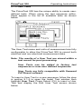
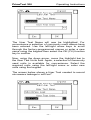
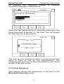
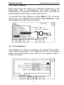
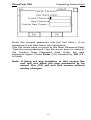
Operating Instructions
Bracken Hill
South West Industrial Estate
Peterlee
Co Durham
SR8 2SW
ENGLAND
Tel: +44(0)191 5863511
www.seaward.co.uk
[email protected]
[email protected]
Part Number 305A563 Revision 3
December 2007
© 2007 Seaward Electronic Ltd
PrimeTest 300
Operating Instructions
-2-
PrimeTest 300
Operating Instructions
Figure 1 PrimeTest 300 Front View
Figure 2 PrimeTest 300 End View
-3-
PrimeTest 300
Operating Instructions
Figure 3 Earth Continuity Measurement
Figure 4 Insulation Measurement (Class II)
-4-
PrimeTest 300
Operating Instructions
Figure 5 IEC Lead Test
Figure 6 Class II Leakage Measurement
-5-
PrimeTest 300
Operating Instructions
Figure 7 Class I Leakage Current Measurement
Figure 8 RCD and Earth Loop Test
-6-
PrimeTest 300
Operating Instructions
Limited Warranty & Limitation of Liability
SEAWARD Electronic Limited guarantees this product to
be free from defects in material and workmanship under
normal use and service for a period of 1 year. The
period of warranty will be effective at the day of delivery.
(c) Copyright 2005
All rights reserved. Nothing from this edition may be
multiplied, or made public in any form or manner, either
electronically, mechanically, by photocopying, recording,
or in any manner, without prior written consent from
SEAWARD Electronic Limited. This also applies to
accompanying drawings and diagrams.
Due to a policy of continuous development SEAWARD
Electronic Limited reserves the right to alter the
equipment specification and description outlined in this
publication without prior notice and no part of this
publication shall be deemed to be part of any contract
for the equipment unless specifically referred to as an
inclusion within such contract.
-7-
PrimeTest 300
Operating Instructions
Table of Contents
1.0
2.0
3.0
User Notes…………………………….. 12
Safety Notes……………………………13
Accessories…………………………… 15
3.1 Standard Accessories…………… 15
4.0 Unit Description………………………. 16
5.0 Getting Started……………………….. 17
5.1 Charging new batteries…………. 17
5.2 Power on…………………………… 17
5.3 How to navigate menus…………. 17
5.4 Battery Health Check……………… 18
5.5 Connecting to Accessories.………. 18
6.0 Data Transfer…………………………. 18
6.1 Download to PC………………….. 19
6.2 Upload from PC…………………… 19
6.3 Send/Receive Config Data……… 21
7.0 View Saved Data ………………………... 23
7.1 Search………………………………… 24
7.2 Options ……………………………….. 24
7.3 Viewing Test Details……………….. 25
8.0 Memory Options………………………… 26
9.0 Configuration……………………………. 27
9.1 Edit Test Sequences……………….. 27
9.1.1 Edit Sequence………………. 28
9.1.2 Copy Sequence…………….. 28
9.1.3 Delete Sequence……………. 28
9.1.4 Creating a New Sequence… 29
9.1.5 User Tests……………………. 31
9.1.6 Print Sequence……………… 33
9.2 Set Date/Time ………………………... 34
9.3 Bluetooth Favourites………………. 34
9.4 Restore Factory Settings………….. 34
9.5 Restore Factory Sequences………. 34
9.6 Verify Calibration……………………. 34
10.0 User Options………………………….. 35
10.1 Test Options………………………. 35
10.1.1 Asset ID……………………….. 36
10.1.2 Start Increment………………..36
10.1.3 On Test Failure………………..36
10.1.4 After Test……………………… 36
10.1.5 Comments…………………….. 38
10.2 Preferences……………………….. 39
10.2.1 Display Time ………………… 39
-8-
PrimeTest 300
Operating Instructions
10.2.2 Set Contrast…………………. 39
10.2.3 Auto Off Time……………….. 40
10.2.4 Data Entry……………………. 40
10.2.5 Backlight Mode……………… 40
10.2.6 Type of User…………………. 40
10.2.7 Tones…………………………. 40
10.3 Change User………………………. 41
10.4 Change Password……………….. 43
11.0 Manual Test Functions……………… 45
11.1 Earth Continuity………………….. 45
11.2 Insulation Resistance……………. 46
11.3 IEC Lead…………………………… 47
11.4 Class II Leakage Current………… 48
11.5 Class I Leakage Current…………. 49
11.6 Earth Loop Resistance…………… 50
11.7 RCD Trip Time ……………………. 51
12.0 Bluetooth Functions…………………. 52
12.1 Bluetooth USB Adapter…………. 52
12.2 Bluetooth Favourites…………….. 52
12.3 Bluetooth Connection to a PC..…. 57
13.0 Automatic Test Mode……………….. 58
13.1 Entering an Asset ID…………….. 58
13.2 Entering Site Information……….. 60
13.3 Entering Location Information…. 64
13.4 Selecting a Test Sequence……... 66
13.5 Frequency of inspection………… 67
13.6 Running the Test Sequence……… 68
13.7 Options…………………………….. 76
13.7.1 View Results ………………… 77
13.7.2 Information…………………... 77
13.7.3 Print Label…………………… 78
13.7.4 Print Result………………….. 79
14.0 Electrical Specification……………… 80
15.0 Environmental Specification……….. 83
16.0 Maintenance………………………….. 84
16.1 Preparation………………………… 84
16.2 Securing………………………….… 84
16.3 Cleaning………………………….… 85
16.4 Battery Charging………………….. 85
16.5 Battery Replacement……………… 86
16.6 Replacing All Fuses……………… 86
16.7 Service and Calibration…………. 88
16.8 Spares……………………………… 89
17.0 Useful Information…………………… 90
-9-
PrimeTest 300
Operating Instructions
DECLARATION OF CONFORMITY
As the manufacturer of the apparatus listed, declare
under our sole responsibility that the product:
PRIMETEST 300
To which this declaration relates are in conformity with
the relevant clauses of the following standard:
IEC 61010-1:2001
Safety requirements for electrical equipment for
measurement, control, and laboratory use – Part 1:
General requirements.
IEC 61326:1998
Electrical equipment for measurement, control and
laboratory user-EMC Requirements
Performance: The
instrument
operates
within
specification when used under the
conditions in the above standards EMC
and Safety Standards.
The product identified above conforms to the
requirements of Council Directive 89/336/EEC and
73/23 EEC.
Seaward Electronic Ltd is registered under BS EN
ISO9001:2000 Certificate No: Q05356.
- 10 -
PrimeTest 300
Operating Instructions
Introduction
The PrimeTest 300 is a hand held, battery powered,
multifunction test instrument capable of performing a
comprehensive range of safety tests, including:
Earth Continuity
Insulation Resistance
IEC Cord Test
Class I Leakage Current
Class II Leakage Current
RCD Trip Time
Earth Loop Resistance
Power socket wiring check
User defined tests
The unique User Test facility in the PrimeTest 300
allows tests to be carried out on any electrical or nonelectrical appliance.
In addition to the standard electrical safety tests, test
records for items such as Fire Extinguishers, Microware
Ovens, Emergency Lighting can now be created and
stored. Test records can be downloaded to PATGuard
for complete traceability.
The PrimeTest 300 is shipped complete with NiMH
rechargeable batteries and charger to allow greater
flexibility and portability.
The PrimeTest 300 uses the latest in wireless
technology to communicate with the range of available
accessories.
- 11 -
PrimeTest 300
1.0
Operating Instructions
User Notes
These operating instructions are intended for
the use of adequately trained personnel.
The following symbols are used in these operating
instructions and on the PrimeTest 300.
Warning of electrical danger!
Indicates instructions must be followed to
avoid danger to persons.
Caution, follow the documentation! This
symbol indicates that the operating
instructions must be adhered to in order to
avoid danger.
Note: The PrimeTest 300 is equipped with context
sensitive help, providing useful advice and
guidance on the safe use of this product.
When help is available a HELP icon will
appear above the function key F1.
- 12 -
PrimeTest 300
2.0
Operating Instructions
Safety Notes
This PrimeTest 300 has been built and tested in
accordance with:
IEC 61010-1: 2001.
IEC 61557 part 1, 2, 4 and 10.
To ensure safe operation of the unit, all notes and
warnings in these instructions must be observed at all
times.
This instrument may be used on electrical
circuits which comply to over voltage
category II.
Attention! During Insulation Resistance tests
high voltage levels occur within the PrimeTest
300.
The tester and all associated cables and leads
must be checked for signs of damage before
equipment is operated.
Where safe operation of the tester is no longer possible
it should be immediately shut down and secured to
prevent accidental operation.
It must be assumed that safe operation is no longer
possible:
- if the instrument or leads show visible signs of damage
or
- the instrument does not function or
- after long periods of storage under adverse
environmental conditions.
Never attempt to charge non-rechargeable
cells in the PrimeTest 300.
Always check that the correct NiMH batteries
are fitted before connecting the charger.
Only use the Seaward PT- 01 charger to
charge the batteries in the PrimeTest 300.
- 13 -
PrimeTest 300
Operating Instructions
- Do not operate the PrimeTest 300 in an
explosive gas or dust environment.
- Do not touch the bare tip of the measuring
lead.
The PrimeTest 300 has been designed to
make measurements in a dry environment.
It must not be used for making measurements
on electric circuits with nominal voltage
greater than 300 V AC/DC.
- 14 -
PrimeTest 300
3.0
Operating Instructions
Accessories
3.1 Standard Accessories
The PrimeTest 300 is supplied with the following items:
3.1.1
3.1.2
3.1.3
3.1.4
3.1.5
3.1.6
3.1.7
3.1.8
3.1.9
3.1.10
1 off PrimeTest 300 unit
1 off professional carry case
1 off mains cord
1 off 1.2 M test lead black
1 off alligator clip, black
6 off Nickel Metal Hydride cells (size LR6)
1 off Battery charger
1 off USB Bluetooth Adapter (with CD-ROM
and manual)
1 off Operating Instruction Manual
1 off Utilities CD-ROM
It should be noted that the following part of the
PrimeTest 300 is user serviceable and must be replaced
with appropriate part as detailed below:
-
1 off fuse, 1 ¼ “ X ¼ “ 10A T, 250 V (27B117)
Do not open unit, no other serviceable parts.
- 15 -
PrimeTest 300
4.0
Operating Instructions
Unit Description
Refer to fig. 1 and fig. 2.
The PrimeTest 300 is a hand held, multi function,
instrument designed to perform electrical safety tests on
Class I and Class II equipment as well as performing
installation checks.
Identifying parts of the unit
1
LCD Display
2
ON/START key. Used to switch the PrimeTest
300 on or to start manual and automatic tests
3
OFF/STOP key. Used to switch the PrimeTest
300 off or to stop manual and automatic tests
4
F1 – F4 Function keys. The purpose of these
keys changes depending upon the mode of the
instrument. The lower part of the LCD display
describes these functions.
5
Arrow keys. These keys are used to navigate
the menu system and set up the instrument.
6
EUT socket. Fit the mains plug of
Equipment Under Test into this socket.
7
Charger Inlet. Fit the Seaward PT-01 Charger
into this socket.
8
IEC Mains Inlet. Fit the Seaward mains cable
into this socket. Required during powered tests.
Also used for testing IEC mains leads.
9
Probe socket. Plug the black lead into this
socket.
- 16 -
the
PrimeTest 300
5.0
Operating Instructions
Getting Started
5.1 Charging New Batteries
Before using the PrimeTest 300 for the first time the
rechargeable cells provided will need to be inserted into
the unit and then charged. See section 16.4.
5.2 Power On
Switch on the PrimeTest 300 by pressing, and holding,
the green ON/START key. After 2-3 seconds the unit
will beep and the display will show a ‘boot up screen’.
This screen will show the firmware version installed.
The first time the PrimeTest 300 is powered up the User
will be automatically set to Admin. The Admin user
gives full access to all the menus and functionality of the
unit.
For further information about changing User and
Password see section 10.3 – Change User & section
10.4 – Change Password.
The PrimeTest 300 will now be ready to use in Manual
mode. Refer to section 11 for more details.
5.3 How to Navigate Menus
Most of the functions within the PrimeTest 300 can be
accessed from the menus.
Press Menu (F4) to select the main menu. Use the
up/down arrow keys to highlight the desired function or
sub-menu. Press either OK (F4) or the right arrow key to
select.
Note: An alternative method of navigating the menus
is to use the Fast Key option. Press Menu (F4)
and note that each menu option has a letter
underlined. By pressing that letter key the
menu option will be selected.
In many instances, the right arrow can also be
used to select a menu option.
- 17 -
PrimeTest 300
Operating Instructions
5.4 Battery Health Check
While the PrimeTest 300 is powered on there are
periodic checks of the batteries. As the batteries
discharge the symbols below will appear on the right
side of the LCD. If there is no battery symbol on the
display the batteries are good/fully charged.
Batteries still good
Batteries still good
This symbol will flash indicating the batteries are
ready for replacement/re-charge. Note:-Tests
performed with the batteries in this state are still
valid.
This symbol will flash for 2-4 seconds
accompanied by a beeping sound. The unit will
then power itself off. Batteries must be replaced/recharged.
5.5 Connecting to Accessories
Before using the PrimeTest 300 to perform tests it is
necessary to ensure the unit is ready to work with the
various accessories that the user has. Instructions for
this can be found in section 12 - Bluetooth Functions.
6.0 Data Transfer
Data transfer is used to transfer records and
configuration data to and from a PC load a logo in
bitmap format for use with the Seaward Test ‘n’ Tag
print system.
- 18 -
PrimeTest 300
Operating Instructions
The Data Transfer functions are accessed by pressing
Menu (F4), selecting Data Transfer using the arrow
keys and pressing OK (F4).
6.1 Download to PC
This feature is used to download records to a PC. Select
Download to PC and press OK (F4) to accept. The
PrimeTest 300 will now attempt to make a Bluetooth
connection with the Computer that has been configured
as Bluetooth Favourite.
Initially, the Bluetooth status icon will display the egg
timer for a few seconds, as shown above, while the
connection is established. When the connection is
established and ready to communicate the Bluetooth
status icon will change to show the Bluetooth icon as
shown below.
- 19 -
PrimeTest 300
Operating Instructions
The PrimeTest 300 is now ready to transfer data. No. of
assets shows the number of records that will be
downloaded. Ensure that the PC application is ready to
receive data then press Send (F4).
A progress bar, as shown below, will now follow the data
transfer until download is complete.
6.2 Upload from PC
Select the Upload from PC option from the Data
Transfer menu. The PrimeTest 300 will now attempt to
establish a Bluetooth connection to the PC as previously
described in 6.1 Download to PC. The PrimeTest 300 is
now ready to receive upload data from a PC.
- 20 -
PrimeTest 300
Operating Instructions
6.3 Send/Receive Config Data
This feature can be used to transfer Site, Location,
User and Comments lists to/from a PC. It can be used
to configure individual PrimeTest 300 units with identical
Site, Location, User and Comments lists.
6.3.1 Send Config Data
To Send configuration data from a PC, press Menu
(F4), select Data Transfer using the arrow keys, select
Send/Receive Config Data and press OK (F4).
The PrimeTest 300 will now attempt to connect to the
Bluetooth Favourite PC. When a connection has been
established the display will be as shown below.
Open the Bluetooth Downloader application on your PC
and check that the Com Port for the Bluetooth serial port
(provided by the Bluetooth USB adapter) is selected.
The baud rate will default to the correct value of 57600.
The Send (F4) key will transfer the Site, Location, User
and Comments list from the PrimeTest 300 to the PC as
text which will appear in the Bluetooth Downloader
screen.
Note: The file transfer can be made using any
suitable PC application such as the Seaward
Bluetooth Downloader or Hyperterminal
capable of sending and receiving a text file.
- 21 -
PrimeTest 300
Operating Instructions
Data is transferred to the PrimeTest 300 using the
format shown below:
[SiteName]
London
Leeds
Newcastle
[LocationName]
Sales Office
Eng Office
[UserName]
Tom
Dick
Harry
[Comment]
Printer
Photocopier
Projector
[END]
Note: The maximum number of entries for each
field is SiteName (40), LocationName (50),
UserName (40) and Comment (80).
If the data is transferred using the Seaward Bluetooth
Downloader, a copy of this data can be saved as a text
file as follows:
Drag the mouse over the text
Pressing CRTL+C on the PC keyboard to copy the
highlighted text.
Open a text editor such as Windows Notepad
Pressing CRTL+V on the PC keyboard to paste the
highlighted text.
Save the file.
The configuration data can be modified to add new
Sites, Locations, Users or Comment information and
sent back to the PrimeTest 300.
- 22 -
PrimeTest 300
Operating Instructions
6.3.2 Receive Config Data
Follow the steps above in Send Config Data to run the
Bluetooth Downloader and connect the PrimeTest 300
to your PC.
Click on File on the Bluetooth Downloader menu and
select Send File. This will open a window allowing you to
select the text file containing your Site, Location, User
and Comments configuration data. Select the required
file and click on Open. The Bluetooth Downloader will
now transfer the configuration file to the PrimeTest 300.
When the transfer is complete the PrimeTest 300 screen
will display a message as shown below.
If the transfer is not successful, check that the format of
the configuration file exactly matches that specified.
Note: The Config file must be ASCII text and the last
entry must be the [END] statement.
7.0 View Saved Data
This function allows saved data to be reviewed and
transferred to PC or Pass/Fail Label. From the main
menu select View Saved Data and press OK (F4) to
accept.
The display will now show a list of previously saved
results as shown below.
- 23 -
PrimeTest 300
Operating Instructions
7.1 Search
The Search (F1) function is used to search through
saved data. The search filter is shown below.
Saved data can be filtered by Asset ID, Site, Location or
Test Status. Wildcards will return all records. In the
example above, the search will return results for all
Asset ID from all Sites, all Locations and all Test Status.
Note: Filtered search can be used to selectively
download or delete assets.
7.2 Options
The Options (F3) key allows operations to be performed
on results returned from the Search function.
- 24 -
PrimeTest 300
Operating Instructions
This allows selected records to be printed onto labels,
downloaded to PC or deleted from memory. Individual
assets can also be deleted by selecting Delete Single
Asset.
Example: The following steps would delete all records
for Site “My town.”
Menu (F4)
Select View Saved Data
OK (F4)
Search (F1)
Select Site “My town”
OK (F4)
Options (F3)
Delete All Assets
7.3 Viewing Test Details
Using the arrow keys, highlight the required record and
press Select (F4). The Test Details for the highlighted
record will now be displayed.
- 25 -
PrimeTest 300
Operating Instructions
8.0 Memory Options
Memory options is used to view information about the
PrimeTest 300 memory status. Press Menu (F4), use
the arrow keys to select Memory Options and press
OK (F4) to accept.
The display shows the number is asset records currently
stored, the remaining memory space, number of assets
deleted and number of assets in upload memory.
The nature of Flash memory is such that when records
are deleted only the reference to the data is removed.
The data still remains and will use memory space. The
memory must be erased in order to release memory
used by deleted records.
If the Erase (F4) key is pressed, a prompt is shown
below. To erase the memory press Yes (F4).
- 26 -
PrimeTest 300
Operating Instructions
9.0 Configuration
The configuration facility is used to edit test sequences,
set date and time, and configure Bluetooth connections.
It is also possible to restore factory settings and/or test
sequences using this function.
The configuration menu is located in the main menu list
and presents the options shown below.
9.1 Edit Test Sequences
The PrimeTest 300 is supplied with 13 pre-configured
test sequences covering a variety of types of electrical
equipment. The test sequence editor can be used to
modify test sequences or create new test sequences.
Note: The PrimeTest 300 can store 37 user
defined test sequences, in addition to the
13 pre-configured test sequences.
Press Menu (F4), select Configuration then Edit Test
Sequences and press OK (F4) to open the Edit Test
Sequences window. The Options (F3) key will display
the available options as shown below.
- 27 -
PrimeTest 300
Operating Instructions
The PrimeTest 300 allows the user to Edit, Copy, Delete
or Print an existing sequence or create a New
sequence.
9.1.1 Edit Sequence
To modify an existing test sequence, select Edit
Sequence from the menu shown above to open the test
sequence editor. Details on how to use the test
sequence editor are given in section 9.1.4.
9.1.2 Copy Sequence
A copy of an existing test sequence can be made and
subsequently modified to create a new sequence. The
copy will be identical to the source and will have the
same sequence name. To avoid confusion, the copy
should be renamed by pressing Edit (F4). The copy can
be further edited as described in section 9.1.4.
9.1.3 Delete Sequence
Sequences can be deleted if no longer required to make
space for new sequences. A confirmation prompt is
presented to avoid accidental deletion.
Note: If a sequence is accidentally deleted the
factory Sequences can be restored by
following the steps in section 9.5
- 28 -
PrimeTest 300
Operating Instructions
9.1.4 Creating a New Sequence
A new test sequence can be created using this option.
The default name for a new sequence is “New
Sequence n” where n is the next available sequence
number. There are 13 factory sequences and so the first
time New Sequence is used the default name is “New
Sequence 14”.
To build the new sequence, use the arrow keys to
highlight the sequence name and press Edit (F4) to
open the sequence editor as shown below.
Pressing Edit (F4) allows the sequence name to be
changed.
To insert a test into the sequence, press Insert (F1) to
open the Insert Test window and use the left or right
arrow key to show the list of available tests.
- 29 -
PrimeTest 300
Operating Instructions
Now scroll through the list of default tests until the
required test is highlighted and press Select (F4).
Note: A unique feature of the PrimeTest 300 is the
ability to create User defined tests. For full
details of this feature refer to section 9.1.5
If the selected test has user definable parameters the
Edit New Test window will open e.g. if an Insulation
Resistance test is selected the window below will open.
The required parameters can be chosen by selecting the
appropriate field and entering the required value using
the keypad.
Note: A decimal point is entered by pressing Shift
(F1) followed by the “2” key.
In the example Insulation Test above, the required
duration in seconds, pass/fail threshold in MW and
number of times the test is to be repeated can be
entered using the keypad. When the required data has
been entered, press OK (F4) to accept.
The new test will now appear in the sequence with the
values entered for each parameter shown.
To add further tests, position the highlight bar at the
required point in the sequence and press Insert (F4).
Note: Tests are inserted into the sequence in the
position above the highlight bar.
- 30 -
PrimeTest 300
Operating Instructions
9.1.5 User Tests
The PrimeTest 300 has the unique ability to create userdefined tests. When using the test sequence editor,
these appear in the list of available tests as shown
below.
The User Test name and units of measurement are fully
configurable to allow the PrimeTest 300 to record both
electrical and non-electrical measurement data.
Note: The results of a User Test are stored within a
test record for post processing.
User Tests can be added to factory test
sequences or new user defined sequences.
User Tests are fully compatible with Seaward
PATGuard software.
To insert a User Test in a new sequence follow the step
in section 9.1.4 to open the Insert Test window then
highlight User Test. Press Select (F4) to insert a User
Test and display the Edit User Test screen shown
below.
- 31 -
PrimeTest 300
Operating Instructions
The User Test Name will now be highlighted. For
convenience a selection of commonly used names have
been entered. Use the left/right arrow keys to scroll
through the factory-programmed names or enter a new
name using the keypad then select the OK (F4) function
key to confirm.
Now, using the down arrow, move the highlight bar to
the User Test Units field. Again, a selection of commonly
used units is available for convenience. Select the
required units using the left/right arrow or enter new
units using the keypad.
The screen below shows a User Test created to record
microwave leakage in mW/cm2.
- 32 -
PrimeTest 300
Operating Instructions
An example test sequence created to measure
microwave leakage is shown below.
When this test sequence is run using the Automatic Test
Mode described in section 13, the User Test will prompt
for data input as shown below.
The user is now required to enter a measurement and
select a Pass or Fail for this measurement. The
measurement and Pass or Fail information is now stored
as part of the test record.
9.1.6 Print Sequence
This feature allows test sequences to be sent to the
Bluetooth Favourite printer.
- 33 -
PrimeTest 300
Operating Instructions
9.2 Set Date/Time
The Primetest 300 is equipped with a real-time clock. To
alter the date or time press Menu (F4), select
Configuration then Set Date/Time and press OK (F4).
Select the values to be changed using the arrow keys,
enter the required value using the keypad and press OK
(F4) to accept.
Note: The time must be entered using a colon to
separate the hours and minutes. A colon is
entered by pressing Shift (F1) followed by the
“3” key.
9.3 Bluetooth Favourites
Refer to section 12 for full details on using Bluetooth.
9.4 Restore Factory Settings
The factory settings can be restored at any time using
this function. The Site, Location and User list will be
restored to the factory settings.
Note: User defined Site, Location and Users lists will
be removed.
9.5 Restore Factory Sequences
The factory test sequences can be restored at any time
using this function.
Note: New or modified test sequences will be
removed if the factory sequences are restored.
9.6 Verify Calibration
After 12 months have elapsed since the last verification
or calibration, the PrimeTest 300 real-time clock will
remind users that verification is required. Contact an
approved Service Agent to arrange verification.
Note: Verify Calibration is password protected and
can only be accessed by an approved Service
Agent.
- 34 -
PrimeTest 300
Operating Instructions
10.0 User Options
Each User has the option to customise aspects of the
PrimeTest 300 in accordance with their needs or
preferences. Changes to the set up of the unit will be
stored against the name of the active User.
To access the User Options, press Menu (F4). Use the
arrow keys to highlight and select User Options. This
will display the menu shown below.
10.1 Test Options
Test Options is used to configure the Asset ID counter,
Test Failure and After Test options and the Comments
fields. The Test Options are split into two pages, page 1
is shown below.
- 35 -
PrimeTest 300
Operating Instructions
10.1.1 Asset ID
This can be set to automatically increment the ID
number at the end of each test, present a blank field or
Repeat Last ID.
10.1.2 Start Increment
This field sets the number from which the auto
incrementing asset ID begins counting.
10.1.3 On Test Failure
In the event of a test failure during an automatic
sequence, the PrimeTest 300 can be configured to
either End Test, which will terminate the test sequence
or Fail Menu, which will present a list options.
Fail Menu gives the option to
restart the test, restart the
appliance (from the first test), end
the appliance (and record a fail
result) or abort the appliance.
Note: Restart Test is useful for coping with
situations such as forgetting to connect the
earth continuity probe.
End Appliance will record a Fail result whereas
Abort Appliance does not record a result.
10.1.4 After Test
There is a choice of 4 actions to be carried out at the
end of a test sequence.
- 36 -
PrimeTest 300
Operating Instructions
New Test will auto save at the end of a test sequence
and then open the Asset Details window ready for a new
test.
Download will auto save at the end of a test sequence
and then open the Download the PC window. When the
Download to PC window is closed the tester will proceed
to the next test and open the Asset Details window.
Print Label will auto save at the end of a test sequence
and then open the Print window. When printing is
complete, the tester will proceed to the next test and
open the Asset Details window.
Options Menu will auto save at the end of a test
sequence and then open the Test Details window as
shown below.
- 37 -
PrimeTest 300
Operating Instructions
Pressing New Test (F2) will proceed to the Asset
Details window, ready for a new test. Pressing Options
(F3) will open a list of options including View Results,
Information, Print Label, Print Result and Write RFID
Tag.
10.1.5 Comments
The comment fields are configured on page 2 of the
Test Options. The tab key
(F3) is used to toggle
between the Test Options pages.
Comments are entered after each test is performed. The
Comments option allows the user to present the
comments window after tests: always, only if the result
is a pass, only if the result is a fail or never.
New Comments allows the user to set the comments of
a new test to be Clear or Same as Last comments.
Comments Line allows the field descriptor for each of
the four comment lines to be changed to show Notes,
Asset Description, Asset Group, Make, Model or Serial
Number as required.
- 38 -
PrimeTest 300
Operating Instructions
10.2 Preferences
There are a number of general features within the
PrimeTest 300 that can be setup/customized for
individual users.
Press Menu (F4). Use the arrow keys to highlight and
select User Options followed by Preferences. Press
OK (F4).
The first field shows the User Name. Any changes made
to these preferences will be stored against this User
only. Use the up/down arrow keys to highlight the
desired feature. Once the required preferences have
been setup press OK (F4) to store the changes. Esc
(F2) will exit this screen without saving the changes.
10.2.1 Display Time
This feature allows the time to be displayed on the LCD
display. Use the left/right arrow keys to adjust.
10.2.2 Set Contrast
This feature allows the contrast of the display to be set.
Use the left/right arrow keys to adjust.
- 39 -
PrimeTest 300
Operating Instructions
10.2.3 Auto Off Time (mins)
The PrimeTest 300 will power itself off after a period of
inactivity. This time is set here. Use the left/right arrow
keys to adjust the value between 1 minute and 10
minutes.
10.2.4 Data Entry
In Automatic mode it is required that an asset ID be
entered prior to starting a test sequence. Data entry can
be set to keypad only, keypad and barcode scanner or
keypad and RFID wand. Selecting Barcode Comments
will allow the keypad and barcode scanner to be used
for entering both the Asset ID and the Comments. Use
the left/right arrow keys to set.
Note: In data entry mode the unit will automatically
try to connect to a barcode scanner or RFID
wand via the internal Bluetooth module – if
neither is available this feature is simply
draining the batteries un-necessarily. In this
instance it is recommended that the unit be set
to Keypad only.
10.2.5 Backlight Mode
The backlight on the PrimeTest 300 can be set to either,
Always Off, Always On or come on in Power Save
mode. Power Save mode ensures that the backlight
comes on when a key is pressed and stays on for
several seconds before switching itself off again. Use
the left/right arrow keys to set.
10.2.6 Type of User
The user type can be set to Novice or Expert. For
Novice users, additional help prompts are provided
during test sequences.
10.2.7 Tones
The Tones (F3) key will open a screen which will allow
the various tones to be set up, i.e. Beep on Key Press or
Beep on Warning etc. Use up/down arrow keys to
- 40 -
PrimeTest 300
Operating Instructions
highlight desired function and the left/right arrow keys to
set.
10.3 Change User
The PrimeTest 300 has a password protected User
system to prevent unauthorised modifications to the
configuration.
There are two levels of access. When logged in as
Admin full access is available to all configuration
options as shown below.
The Change User option is used to change the active
User.
From the User Options menu, select Change User and
press OK (F4). The screen will now be as shown below.
- 41 -
PrimeTest 300
Operating Instructions
Use the left/right arrow keys to change to an existing
User Name or press New (F3) and type in a new name
as shown below.
Press OK (F4) to accept the new user name.
This new user will have no password set as default. If a
password is required see section 10.4 – Change
Password. Press OK (F4) to finish.
Note: If a User has been set up along with a
password this password must be entered in
the Password field of the Change User screen.
The unit will not allow this User to be selected
if the password is incorrect.
As the active User has been changed from Admin,
access to the configuration menus has been removed.
When logged in as any other User access is restricted,
as can be seen below, where the unavailable
configuration options have a line through them.
This feature allows an administrator to configure the
instrument and then prevent other users from making
any modifications.
- 42 -
PrimeTest 300
Operating Instructions
Note: Access for other Users is only restricted after
a password has been set for the Admin User.
If Admin password is blank, all Users have full
system access.
10.4 Change Password
Note: The default password for all Users is blank.
First ensure that the required active User name has
been selected as described in section 10.3.
Press Menu (F4). Use the arrow keys to highlight and
select User Options followed by Change Password.
Press OK (F4). The screen now shows the Change
Password display.
- 43 -
PrimeTest 300
Operating Instructions
Enter the current password into the first field – if no
password is set then leave this field blank.
Use the arrow keys to move to the New Password field.
Type the new password. Use the arrow keys to move to
the Confirm New Password field. Enter the new
password again. Press Enter (F4) followed by OK (F4)
to finish.
Note: If there are any mistakes in this screen the
unit will not allow the new password to be
stored. Esc (F2) will exit this screen without
saving changes.
- 44 -
PrimeTest 300
Operating Instructions
11.0 Manual Test Functions
Once in Manual mode the tester can perform one of
seven tests as described below. The desired test can be
selected by using either the left/right arrow keys or
Menu (F4) followed by Manual Mode.
An icon displayed in the top left of the LCD display
identifies the selected test.
11.1 Earth Continuity
Refer to fig. 3.
This test is applicable to Class I equipment
only.
This test will check that the connection between the
earth pin in the mains plug of the appliance and the
metal casing of the appliance is satisfactory and of
sufficiently low resistance.
A DC test current of ±200mA is applied between the
earth pin of the mains supply plug and the earth bond
test lead clip/probe. The worst-case result is shown on
the display.
Press Setup (F3) to set the Test Duration and Pass/Fail
limit. Use the arrow keys to highlight and set. The
pass/fail limit can be calculated whilst in this mode by
pressing Calc (F3). Enter the type and length of cable
and a new limit will be calculated. This can be
overridden by selecting the limit from the list. Press OK
(F4) when complete. Esc (F2) will exit setup mode
without saving changes.
If an Earth Bond lead other than that supplied with
the PrimeTest 300 is to be used for this test its
resistance can be ‘nulled’ out by fitting the probe end
into the EUT earth socket and pressing F2. The icon
above will be displayed on the left side of the LCD to
indicate this has taken place. Press F2 again to cancel.
Note: switching off the PrimeTest 300 will not cancel the
‘probe zero’.
Fit the Appliance mains plug into the EUT outlet.
Connect the Earth Bond lead to the appliance metal
- 45 -
PrimeTest 300
Operating Instructions
part. Press the green START key to begin the test. The
test will run for the duration set. To end the test before
the test time expires press the red STOP key.
Note: The PrimeTest display will show real time
measurements during an Earth Continuity test.
The reading shown at the end of the test is the
peak value recorded during the test. This can
be used to detect a momentary break in the
earth path e.g. damaged power cords or loose
mains plug connections.
A Pass or Fail is determined by comparing the
peak value measured during the test with the
pre-set limit.
11.2 Insulation Resistance
Refer to Fig. 4
This test is applicable to Class I and Class II
equipment.
This test is used to verify that the mains supply pins are
adequately insulated from earth.
During this test, 500V D.C. is applied between
the earth pin and both the live and neutral pins
of the appliance mains supply plug.
Press Setup (F3) to set the Test Duration and Pass/Fail
limit. Use the arrow keys to highlight and set. Press OK
(F4) when complete. Esc (F2) will exit setup mode
without saving changes.
Press Class (F2) to set the class of the appliance under
test. For a Class II appliance the probe symbol will be
displayed at the top of the LCD display.
For both Class I and Class II appliances fit the
Appliance mains plug into the EUT outlet. For Class II
appliances only connect the Earth Bond lead to the
appliance. Press the green START key to begin the test.
The test will run for the duration set or until the red
STOP key is pressed.
- 46 -
PrimeTest 300
Operating Instructions
11.3 IEC Lead
Refer to Fig. 5
IEC leads are tested in 3 stages, continuity, insulation
and polarity.
The test durations for the each of the 3 stages are fixed.
Press Setup (F3) to set the Pass/Fail limits for
Continuity and Insulation stages. Use the arrow keys to
highlight and set. The pass/fail limit for the continuity
stage can be calculated Calc (F2). Enter the type and
length of cable and a new limit will be calculated. This
can be overridden by selecting the limit from the list.
Press OK (F4) when complete. Esc (F2) will exit setup
mode without saving changes.
To perform an IEC lead test, connect the IEC socket
side of the lead into the IEC inlet plug on the PrimeTest.
Connect the mains plug side of the lead into the EUT
socket.
To start the IEC lead test, press the green START
button. The earth continuity resistance for the lead is
measured at ±200mA. The display indicates the highest
resistance and the pass/fail status. If this resistance is
less than the pass/fail limit, then the insulation
resistance will be measured.
During an insulation resistance measurement,
a high voltage is applied between Live/Neutral
and the common of the IEC lead.
The insulation resistance of the lead is measured over a
period of 2 seconds. The display shows the final reading
and the pass/fail status. If the insulation resistance is
greater than the pass/fail limit, then the lead polarity will
be checked.
The lead polarity stage checks for short and open circuit
conditions on the live and neutral conductors. It also
checks that the live and neutral wires are not crossed.
The display shows the final result and the pass/fail
status.
- 47 -
PrimeTest 300
Operating Instructions
11.4 Class II Leakage Current
Refer to Fig 6
This test is applicable on Class II Equipment.
The Class II Leakage Test displays the current that
would flow to a person if they touched a conductive part
of the appliance. The leakage current is measured using
a 'body model' of 2kohm as described in IEC 61010-1.
The Tester uses the black test probe to detect any
current flowing from accessible conductive parts of the
appliance to earth via the ‘body model’. The Tester
displays the result in milliamps (mA).
Warning: An insulation resistance test is
recommended
before
performing
any
powered test.
Warning: Always check that an appliance with
moving parts (e.g. an electric drill) is safely
mounted to avoid risk of damage to
equipment or personnel.
Attention: Avoid excessive duration, repeated
tests at high loads.
Press Setup (F3) to set the Test Duration and Pass/Fail
limit. Use the arrow keys to highlight and set. Press OK
(F2) when complete. Esc (F2) will exit setup mode
without saving changes.
Fit the power lead supplied to the PrimeTest 300 and
plug the other end into a suitable mains outlet. Fit the
Appliance mains plug into the EUT outlet. Connect the
Earth Bond lead to the appliance metal part. Press the
green START key to begin the test.
Pre-load check - If the potential load current is too high,
a warning message appears, preventing the user from
continuing. This message will be displayed if a Live to
- 48 -
PrimeTest 300
Operating Instructions
Neutral short exists or
consumption is too high.
the EUT mains current
Internal Relay checks – Before applying power to the
EUT the PrimeTest 300 performs a series of internal
safety checks to verify that internal relays are working
properly.
Once the test has started it will run for the duration set.
To end the test sooner, press the red STOP key.
11.5 Class I Leakage Current
Refer to Fig 7
This test is applicable on Class I Equipment.
The Class I Leakage Current Test displays the current
flowing in the earth conductor of the EUT. This is
measured by determining the difference in current
flowing in the live and neutral conductors.
The Tester displays the result in milliamps (mA).
Warning: Always test the earth continuity
before performing a Class I Leakage Current
test.
Warning: An insulation resistance test is
recommended
before
performing
any
powered test.
Warning: Always check that an appliance with
moving parts (e.g. an electric drill) is safely
mounted to avoid risk of damage to
equipment or personnel.
Attention: Avoid prolonged, repeated use at
full load (13A) and excessive test duration as
this may reduce the life of the unit.
- 49 -
PrimeTest 300
Operating Instructions
Press Setup (F3) to set the Test Duration and Pass/Fail
limit. Use the arrow keys to highlight and set. Press OK
(F4) when complete. Esc (F2) will exit setup mode
without saving changes.
Fit the power lead supplied to the PrimeTest 300 and
plug the other end into a suitable mains outlet. Fit the
Appliance mains plug into the EUT outlet. Press the
green START key to begin the test.
Pre-load check - If the potential load current is too high,
a warning message appears, preventing the user from
continuing. This message will be displayed if a Live to
Neutral short exists or the EUT mains current
consumption is too high.
Internal Relay checks – Before applying power to the
EUT the PrimeTest 300 performs a series of internal
safety checks to verify that internal relays are working
properly.
Once the test has started it will run for the duration set.
To end the test sooner, press the red STOP key.
11.6 Earth Loop Resistance
Refer to Fig 8
This test is applicable to the mains electrical
installation.
This test will check the resistance of the Live to Earth
circuit of the installation.
Warning: The black probe must not be used
when performing an Earth Loop Resistance
test.
The test duration for this test is fixed at approximately
10 seconds.
Fit the power lead supplied to the PrimeTest 300 and
plug the other end into the mains outlet under test. To
start the test, press the green START button.
- 50 -
PrimeTest 300
Operating Instructions
While the PrimeTest 300 performs the test the LCD will
show 0.0Ω flashing. When the test is complete the
measured value will be displayed.
11.7 RCD Trip Time
Refer to Fig 8
This test is applicable to the mains electrical
installation.
This test will pass a sinusoidal current of 30mA down
the earth conductor and measure the time it takes for
the mains supply to trip.
Warning: The black probe must not be used
when performing an RCD test.
Fit the power lead supplied to the PrimeTest 300 and
plug the other end into the mains outlet under test. To
start the test, press the green START button. The
PrimeTest 300 will produce a test current of 30mA r.m.s
in the protective earth of the supply. The test will
commence at the start of a positive half cycle.
The RCD will trip. The time taken to trip will be
displayed.
Reset the RCD. When the PrimeTest 300 detects that
power has been re-applied it will commence the
negative half cycle test. The PrimeTest 300 will again
produce a test current of 30mA r.m.s in the protective
earth of the supply. The test will commence at the start
of a negative half cycle.
The RCD will trip. The time taken to trip will be
displayed.
- 51 -
PrimeTest 300
Operating Instructions
12.0 Bluetooth Functions
The PrimeTest 300 has built in Bluetooth connectivity. It
is possible to connect a variety of devices to the
PrimeTest 300 via the Bluetooth link:
PC – required to download stored data, to upload, to
upload configuration, test and program data.
Barcode Scanner – required for scanning asset labels.
Printers – required for printing pass/fail labels and
barcode labels.
The PrimeTest 300 will automatically search for the
appropriate accessory or device when a function
requiring a connection is performed.
Note: When attempting to print a pass/fail label the
PrimeTest 300 will automatically connect to
the printer assigned in the Bluetooth
Favourites.
Similarly, when data is required from a
barcode scanner, the PrimeTest 300 will
automatically connect to the barcode scanner
assigned in the Bluetooth Favourites.
12.1 Bluetooth USB Adapter
The PrimeTest 300 is supplied complete with a
Bluetooth USB Adapter. This device can be used to add
Bluetooth connectivity to a PC or Laptop which is not
already Bluetooth enabled. Full installation instructions
are provided in the Bluetooth USB Adapter Setup guide.
Note: The adapter must not be plugged into the USB
port until specifically requested to do so by
the install program.
12.2 Bluetooth Favourites
In order for the PrimeTest 300 to automatically connect
to the correct Bluetooth accessory, details of that
accessory must be entered into the Bluetooth Favourites
list.
- 52 -
PrimeTest 300
Operating Instructions
The Bluetooth Favourites list comprises of four sub-lists
(device types), each of which can store up to 3
accessories of the same type. The four sub-lists are
shown below:
Barcode Scanner
Printer (thermal)
Computer
RFID wand
Press Menu (F4). Use up/down arrow keys to highlight
Configuration, press right arrow key to select. Use
up/down arrow keys to highlight Bluetooth Favourites,
press OK (F4) to select.
The following shows how to add a Computer to
Bluetooth Favourites.
Use the up/down arrow keys to highlight the device type
(in this case Computer) then press Setup (F3).
Make sure that the device you want to add to your new
favourites is switched on.
Press Search (F1). The PrimeTest 300 will search for all
discoverable Bluetooth devices within a 10m range. The
time taken to perform the search will vary depending on
the number of Bluetooth devices in range.
- 53 -
PrimeTest 300
Operating Instructions
Wait for the progress bar to complete.
Use the arrow keys to highlight the field labelled “New”
and press the left or right arrow to open the list of
devices which have been found during the search.
Note: If more than 10 Bluetooth devices have been
found the list will show the last 10 devices
found.
In the example above, the search has identified
Bluetooth devices named “GX30” and “My Laptop.”
Note: If the required device is not shown, check that
it is powered on with the Bluetooth function
active then repeat the search.
- 54 -
PrimeTest 300
Operating Instructions
Note: Some Bluetooth devices do not report a
recognisable name and may cause confusion
when setting up Favourites. Turn off or disable
unused Bluetooth devices when configuring
Favourites.
Use the arrow keys to highlight the required device (in
this case My Laptop) and press Select (F4). My Laptop
is now placed in the “New” field as shown below.
Press Add New (F3) to add “My Laptop” to the
Favourite Computer list.
To add further devices to the list of available computers
select the New again, use the arrow keys to select the
required device and press Add New (F3) to add the
chosen device.
Note: Devices that are not required can easily be
removed by selecting the Computer field,
pressing the left of right arrow key to open the
list, highlighting a device and pressing Del
(F3).
- 55 -
PrimeTest 300
Operating Instructions
A PIN number can be entered if required by the device
to be added to the Favourites list.
Note: Seaward accessories do not require a PIN. For
other Bluetooth devices refer to the
manufacturers documentation.
“My Laptop” has been added to the Computer field with
Bluetooth ID.
Note: All Bluetooth devices have a unique ID. The
Bluetooth ID is shown when a device is added
to the Favourites list.
Press OK (F4) to store the changes and return to the
previous screen.
- 56 -
PrimeTest 300
Operating Instructions
“My Laptop” is now a Bluetooth Favourite and the
PrimeTest 300 will automatically establish a connection
with “My Laptop” when using functions that
communicate with a computer e.g. downloading records
to PATGuard.
Note: Press Esc (F2) to exit without saving changes.
If necessary, you can select another device to be set up.
When all your favourite devices have been set up, press
OK and they will be saved.
12.3 Bluetooth Connection to a PC
When the PrimeTest 300 is required to download data
to, or upload data from, a PC it will automatically try to
connect to the PC entered in the Bluetooth Favourites
list (see 12.2 above). If the PC has been set up using
the USB adapter supplied (see 12.1 above) a message
will appear on the PC screen requesting a PIN number –
enter 0000. This should only happen the first time.
Note: Most Bluetooth devices use the default PIN
0000.
Each time a connection is attempted, after the first time,
a message box should appear stating “Bluetooth
Authorisation Request”. Click on this box then OK. This
message box can be prevented if the “Always allow this
device to access this service” box is ticked.
When a good Bluetooth connection is established with
the PC the Bluetooth icon on the PC screen will change
from white to green and the PrimeTest 300 LCD will
show the Bluetooth icon in the top right corner (this is
true
of
a
successful
connection
to
any
device/accessory).
- 57 -
PrimeTest 300
13.0
Operating Instructions
Automatic Test Mode
The automatic mode allows the PrimeTest 300 to
perform a predefined test sequence and store the
results along with details about the equipment under
test.
To perform an Auto Test press the Menu (F4) key to
open the menu.
The Auto Mode will be highlighted. Press OK (F4) or
right arrow to open the Asset Details screen.
13.1 Entering an Asset ID
If the PrimeTest 300 has been configured to accept data
entry from a barcode scanner, the tester will now search
- 58 -
PrimeTest 300
Operating Instructions
for the barcode scanner in Bluetooth Favourites.
Whilst searching, the Bluetooth status icon shows an
egg timer in the top right hand corner of the display.
Note: If the egg timer does not appear check that the
PrimeTest 300 has been configured to accept
data entry form a barcode scanner.
Menu (F4), User Options, Preferences, Data
Entry should be set to Barcode or Barcode
Options.
When a connection to the barcode scanner is
established the status icon changes to the Bluetooth
icon.
An Asset ID can be entered by scanning the ID using a
barcode scanner as shown below.
Alternatively, the Asset ID can be entered using the
- 59 -
PrimeTest 300
Operating Instructions
keypad. Simply enter the required ID in the Asset ID
field as shown below. The function keys can be used to
edit the entry.
When the required ID is shown in the Asset ID field
press the Enter (F4) key to accept. The Asset ID will
now be highlighted as shown below.
13.2 Entering Site Information
Using the arrows, move the cursor to highlight the Site
field as shown overleaf.
Seaward Quick Text
The PrimeTest 300 is equipped with Seaward Quick
Text to greatly reduce the time taken to enter Site,
Location and Comments data.
When a character is entered using the keypad, the
- 60 -
PrimeTest 300
Operating Instructions
PrimeTest 300 will automatically list any appropriate
data currently in memory that begins with the character
that is entered.
A Site can be chosen from the list current stored in the
PrimeTest 300 or a New Site can be entered using the
keypad.
Note: Section 6.2.1 gives details on how to transfer
Site lists from a PC.
13.2.1 Selecting a Site using Quick Text
Simply enter the first letter of the required Site name
using the keypad. If the Site name is currently in the
PrimeTest 300 memory it will be displayed in a list of
available Sites. The example below shows the display if
the “N” key is pressed on a PrimeTest 300 that has been
pre-configured with a list of Sites.
- 61 -
PrimeTest 300
Operating Instructions
The UP/DOWN can now be used to scroll through the
Site list until the required Site is highlighted.
Press Select (F4) to confirm selection.
Note: To see a list of all Sites currently stored in the
PrimeTest 300 memory, simply press the left
or right arrow key when the Site field is
highlighted.
Quick Text can then be used to find a specific Site
or you can simply scroll through the list using the
up and down arrow keys.
- 62 -
PrimeTest 300
Operating Instructions
13.2.2 Adding a new Site
If the required Site is not already in memory, simply use
the keypad to enter the new Site name.
The Edit keys can be used to correct the entry.
When the required data has been entered, press the
Enter (F4) key to accept.
Note: Once a Site name is entered, it is added to the
list of available Sites for future use.
- 63 -
PrimeTest 300
Operating Instructions
13.3 Entering Location Information
Move the cursor to the Location field.
A Location can be selected in the same way as a Site,
using Quick Text to choose from the list previously
stored in memory or a new Location can be entered
using the keypad.
Note: If the LEFT/RIGHT arrows are pressed before
entering a character from the keypad, the full
Location list will be opened.
13.3.1 Selecting a Location using Quick Text
Enter the first letter of the required Location name using
the keypad. If the Location name is currently in memory
it will be displayed in a list of available Locations. The
example below shows the display if the “S” key is
pressed on a PrimeTest 300 that has been preconfigured with a list of Locations.
- 64 -
PrimeTest 300
Operating Instructions
Select the desired Location from the list using the
UP/DOWN arrows and press Select (F4) to confirm.
Note: Section 6.2.1 gives details on how to transfer
Location lists from a PC to the PrimeTest 300
memory.
13.3.2 Adding a new Location
If the required Location is not already in memory,
simply use the keypad to enter the new Location name.
- 65 -
PrimeTest 300
Operating Instructions
The Edit keys can be used to correct the entry.
When the required data has been entered, press the
Enter (F4) key to accept.
13.4 Selecting a Test Sequence
The test sequence is the set of tests that will be
performed on the Asset. The PrimeTest 300 contains a
number of pre-programmed sequences for a variety of
electrical equipment.
Move the cursor to highlight the test sequence field as
shown below.
- 66 -
PrimeTest 300
Operating Instructions
Pressing the Left or Right arrows will open the list of
available test sequences.
Press the index letter next to the required test sequence
name or use the UP/DOWN arrows to navigate through
the list. When the required test sequence is highlighted,
pressing Select (F4) or pressing the LEFT/RIGHT
arrows will select the highlighted sequence.
13.5 Entering the frequency of inspection and
testing
The Test Period is the frequency, in months, of
inspection and testing of the equipment.
- 67 -
PrimeTest 300
Operating Instructions
To enter a value, simply move the cursor to the correct
field using the UP/DOWN arrows
Now enter the required number of months using the
keypad and press Enter (F4) to accept.
The Asset Details are now complete and the PrimeTest
300 is ready to perform the test.
13.6 Running the test sequence
When the required Asset ID, Test Sequence, Site,
Location and Test Period details have been entered,
press the OK (F4) key to initiate the chosen test
sequence.
- 68 -
PrimeTest 300
Operating Instructions
If the red STOP key is pressed during a test then the
test is aborted and the abort menu appears as shown
below:
Restart Test will return to the beginning of the test that
was aborted.
Restart Appliance will return to the beginning of the test
sequence.
Abort Test will skip the test that was aborted and
proceed to the next test in the sequence.
Abort Appliance will abort the test sequence.
The first test in this sequence is a visual inspection. The
default Visual Test consists of a ten-point inspection of
the appliance. After performing the inspection, the
appropriate PASS/FAIL results are entered using the
function keys Pass (F3), Fail (F1) or N/A (F2). Function
key Pass All (F4) allows a PASS result to be entered for
all points of the inspection.
- 69 -
PrimeTest 300
Operating Instructions
This sequence will now progress to the Earth Continuity
test as shown. This test will measure the resistance of
the protective earth path.
The START key icon is flashing, indicating that a key
press is required to initiate the test. The probe icon is
illuminated to indicate that the test probe is required for
this test. Connect the test probe to an exposed metal
part on the equipment under test and press the START
key to begin measurement.
Real time measurement values are displayed whilst the
test is in progress.
- 70 -
PrimeTest 300
Operating Instructions
The test will run until the countdown timer in the
Duration field has reached zero.
Note:
During the test, the mains cord should be
flexed at the points of entry into the
equipment and the mains plug. Changes in
the reading may indicate damage to the
protective earth conductor or a poor
connection.
At the end of the test duration, the PrimeTest 300 will
compare the last reading with the Limit to determine the
outcome of the test. If the last reading is lower than the
Limit, a Pass result is recorded. This is indicated on the
display by a large tick mark next to the measurement
field, as shown below.
- 71 -
PrimeTest 300
Operating Instructions
Similarly, if the last reading is greater than the Limit, a
Fail result is recorded. This is indicated by a large cross
next to the measurement field as shown below.
If the Earth Continuity test results in a Fail and the On
Test Failure is set to End Test the sequence is
terminated.
Note: On Test Failure is set in User Options – Test
Options – On Test Failure.
If the Earth Continuity test results in a Fail and the On
Test Failure is set to Fail Menu the display is as shown
below.
The earth continuity test can be restarted by simply
pressing OK (F4) to select Restart Test.
- 72 -
PrimeTest 300
Operating Instructions
The next test in this sequence is an insulation resistance
test. The display is as shown below.
Note: In order to perform an Insulation Resistance
measurement correctly, the EUT mains switch
must be in the ON position. If the EUT mains
switch is OFF, only the insulation of the power
cord will be tested as the test voltage cannot
be applied beyond the mains switch.
When satisfied that the EUT mains switch is in the ON
position, press the START key to proceed. The display
will now progress to the measurement screen as shown
below.
Note: In Expert Mode the test will begin with the on
screen prompt and START key press.
- 73 -
PrimeTest 300
Operating Instructions
The Class I icon is illuminated to indicate that the
insulation resistance is measured between the
live/neutral conductors and the protective earth.
Note: The probe icon is turned off as the test probe
is not required for Class I insulation resistance
measurements.
The display shows that the measured value is
>200MW. This is greater than the Limit of 1.0 Mohm
hence the tick mark is shown to indicate a Pass result.
Next in this sequence is the Protective Conductor
Current measurement. This is now the preferred term for
what used to be referred to as Earth Leakage.
Note: Mains power is applied to the EUT for this test
and hence the mains must be connected to the
PrimeTest 300.
The PrimeTest 300 will check for the presence of correct
supply before starting a powered test. If the supply is not
present the message shown below is displayed.
Connect a mains supply to the PrimeTest 300 and press
OK (F4) to proceed.
Note: The appliance will be powered during this test.
Make sure it is safe to proceed, particularly
when testing an appliance with moving or
rotating parts, before pressing the START key.
- 74 -
PrimeTest 300
Operating Instructions
The next test in this sequence is a Protective Conductor
Current measurement.
The display now shows the supply voltage and
frequency measured prior to starting the test. The
measured leakage current is shown in real time on both
the digital display and the analogue bargraph.
Note: The vertical bar midway along the analogue
bargraph indicates the Limit value (in this case
5.00mA).
The test sequence is now complete. The display at the
end of a sequence depends upon the options set in
Menu – User Options – Test Options as described in
section 10.1.3.
The example below shows the end of test screen when
Menu – User Options – Test Options has been
configured for Options Menu.
- 75 -
PrimeTest 300
Operating Instructions
The Test Type field indicates whether the sequence
was a visual inspection only or a full test where
measured values were recorded during the test
sequence. Test sequences that do not involve the
recording of measured values have the Test Type is set
to Visual.
13.7 Options
Pressing Options (F3) offers a list of post-test options
as shown below.
This allows the user to view the results of each test
performed, view the test sequence, view information
about the EUT, print the test results or print a label.
- 76 -
PrimeTest 300
Operating Instructions
13.7.1 View Results
This will display the results for each test in the sequence
as shown below.
The Up and Down arrows can be used to scroll through
the test results. The scroll bar on the right hand side of
the display shows the position of the results in the
display window.
13.7.2 Information
This will display the asset description and comment as
shown below.
Note: Asset Description is entered using the Upload
facility on Seaward PATGuard Elite.
- 77 -
PrimeTest 300
Operating Instructions
13.7.3 Print Label
This allows Pass/Fail labels to be printed using the
printer in the Bluetooth Favourites list.
Note: The label image appears on the PrimeTest 300
display exactly as it will appear on the label.
A number of pre-configured label formats are available.
Pressing Change Format (F1) will cycle through the
available formats.
The printed header that appears on certain label formats
can be modified if required. To change the printed
header, press Setup (F3), enter the required text in the
highlighted field and press OK (F4) to accept.
- 78 -
PrimeTest 300
Operating Instructions
Using Change Format (F1) to select a label format that
displays a printed header will now display the text
entered in the setup window as shown below.
A logo can be added to the label by pressing Setup
(F3), selecting the Pass Logo or Fail Logo field and
selecting an option. No will print no logo. PASS.PCX
will print a pass logo. FAIL.PCX will print a fail logo.
<username>.PCX will print the users logo e.g.
JIM.PCX. Alternatively the user can type the name of
the preferred logo.
Note: If the specified logo is not available in the
printer no logo will be printed on the label.
For details on modifying or replacing logo graphics, refer
to the documentation supplied with the ProTag print
system.
13.7.4 Print Result
This allows test results to be printed using the printer in
the Bluetooth Favourites list.
Note: To print results the printer must be fitted with
a paper roll.
- 79 -
PrimeTest 300
Operating Instructions
14.0 Electrical Specifications
14.1 Earth Continuity
Test Current (2Ω load)
Test Circuit Voltage
Test Duration
Pass/Fail Limit
Display Range
Measuring Range
Resolution
Accuracy
14.2
±200 mA
± 4V min
2, 5, 10, 20, 30 seconds
User Defined
0.00 – 19.99Ω
0.01 – 19.99Ω
0.01Ω
± 5% ±2 digits
Insulation Resistance
Test Voltage Open Circuit
Test Voltage @ 1mA
Test Current Short Circuit
Test Duration
Pass/Fail Limit
Display Ranges
Measuring Range
Resolution
Accuracy
14.3
500V +20% / -0%
500V min
<2 mA
2, 5, 10, 20, 30 seconds
User Defined
0.00 – 1.99MΩ
2.0 – 19.9MΩ
20 – 199MΩ
0.01 – 40MΩ
0.01MΩ, 0.00 – 1.99MΩ
0.1MΩ, 2.0 – 19.9MΩ
1MΩ, 20 – 199MΩ
± 5% ±2 digits
IEC Lead Test
This is a 3 part test is made up of:
Earth Continuity – specification as 10.1 above.
Insulation Resistance – specification as 10.2 above.
Polarity Check – checks for: Live open
Neutral open
L/N Short
L/N reversed
- 80 -
PrimeTest 300
14.4
Operating Instructions
Class II Leakage Current
Test Voltage
Max Load Current
Input Impedance
Test Duration
Pass/Fail Limit
Display Range
Measuring Range
Resolution
Accuracy
Mains supply 230V +10% / -15%
10A
2KΩ As per IEC 61010-1 A.1
2, 5, 10, 20, 30 seconds
User Defined
0.00 – 3.50mA
0.10 – 3.50mA
0.01mA
± 5% ±5 digits
Attention: Avoid prolonged, repeated use at
full load and excessive test duration as this
may reduce the life of the unit.
14.5
Class I Leakage Current
Measurement Method
Differential
Test Voltage
Mains supply 230V +10% / -15%
Max Load Current
10A
Test Duration
2, 5, 10, 20, 30 seconds
Pass/Fail Limit
User Defined
Display Range
0.00 – 19.99mA
Measuring Range
0.25 – 19.99mA
Resolution
0.01mA
Accuracy
± 5% ±5 digits
Attention: Avoid prolonged, repeated use at
full load and excessive test duration as this
may reduce the life of the unit.
14.6
Earth Loop Resistance
Test Voltage
Test Current
Test Duration
Pass/Fail Limit
Display Ranges
Measuring Range
Resolution
Accuracy
Mains supply 230V +10% / -15%
Non-trip for 30mA RCD
Approx 10 seconds
User Defined
0.0 – 199Ω
1.0 – 199Ω
0.1Ω, 0.0 – 19.9Ω
1Ω, 20 – 199Ω
± 10% ±2 digits
- 81 -
PrimeTest 300
14.7
RCD Trip Time
Test Voltage
Test Current
Test Duration
Pass/Fail Limit
Display Range
Measuring Range
Resolution
Accuracy
14.8
Operating Instructions
Mains supply 230V +10% / -15%
30mA rms sinusoidal
2000ms max
None
0 – 2000ms
20 – 2000ms
1ms
± 2ms (0ms to 40ms)
± 8ms (41ms to 300ms)
Voltage/Frequency Measurement
Incoming mains voltage and frequency are displayed
during the 4 powered tests only.
Voltage Display Range
Voltage Measuring Range
Voltage Resolution
Voltage Accuracy
Frequency Measuring Range
Frequency Accuracy
- 82 -
0 – 300V
20 – 300V
1V
± 10%
50Hz or 60Hz
Indication only
PrimeTest 300
Operating Instructions
15.0 Environmental Conditions
15.1 The PrimeTest 300 has been designed to perform
tests and measurements in a dry environment.
15.2
Maximum barometric elevation
measurements is 2000M.
for
making
15.3 Overvoltage category IEC 60664/IEC 61010, 300V
Category II.
15.4 Pollution degree 2 according to IEC 61010-1.
15.5 Protective system IP40 according to IEC 60529.
15.6 Electromagnetic compatibility (EMC). Interference
immunity and emitted interference conforming to
IEC 61326-1.
15.7 Operating temperature range of 0°C to 40°C,
without moisture condensation.
15.8 The PrimeTest 300 can be stored at any
temperature in the range -25°C to +65°C (relative
humidity up to 90%). The batteries should be
taken out of the instrument for storage.
- 83 -
PrimeTest 300
Operating Instructions
16.0 Maintenance
Warning: Always ensure that the PrimeTest
300 is disconnected from all voltage sources
before maintenance work is carried out.
16.1 Preparing to work on the PrimeTest 300.
Make the PrimeTest 300 as voltage free as follows,
before opening the instrument;
Power the unit off using the red OFF button, ref fig. 1 (3)
Disconnect the black test lead from the unit
Disconnect the Seaward mains cable, from the mains
inlet socket, ref fig 2 (7).
Disconnect the IEC mains cable, from the IEC socket ref
fig 2 (8).
Disconnect the EUT mains cable, from the EUT socket,
ref fig 1 (6).
16.2 Securing the PrimeTest 300
Under certain conditions safe operation of the PrimeTest
300 can no longer be assumed:
Visible damage of the instrument case.
Incorrect measurement results.
Recognisable abuse to the instrument due to prolonged
storage under improper conditions.
Recognisable abuse to the instrument
extraordinary transportation stress.
due
to
In these cases, the PrimeTest 300 should be
immediately switched off, disconnected from any test or
measurement function and secured to prevent any
further use.
- 84 -
PrimeTest 300
Operating Instructions
16.3 Cleaning
Clean the external case of the PrimeTest 300 with a
clean dry cloth.
Avoid using solvents and abrasive scouring agents to
clean the external case of the PrimeTest 300.
Check the battery contacts and compartment are free of
electrolytic contamination.
Any contamination of the battery contacts
compartment should be cleaned with a dry cloth.
or
16.4 Battery Charging
Never attempt to recharge non-rechargeable
cells in the PrimeTest 300. Always check that
the correct NiMH batteries are fitted before
connecting the charger.
Only use the Seaward PT- 01 charger to
charge the batteries in the PrimeTest 300.
The PrimeTest 300 is supplied with re-chargeable NiMH
batteries.
Power the unit off using the red OFF button, ref fig. 1 (3)
Connect the battery charger to the mains. Once the
charger is connected to mains it is ready for use.
Connect the battery charger to the charger input socket,
ref fig. 2 (7).
Refer to the instructions supplied with the PT-01
charger. The batteries should typically be fully charged
within 4 to 5 hours.
Note: When the external battery charger is plugged
in, the PrimeTest 300 will automatically be
switched off. It is not possible to use the
instrument while the batteries are being
charged.
- 85 -
PrimeTest 300
Operating Instructions
16.5 Battery Replacement
Over a period of time, (typically 1 to 2 years), the
batteries will loose their ability to hold charge. (E.g.
Even when fully charged, they go flat very quickly when
you start using the tester). In this case you will need to
replace the batteries, using the procedure described
here.
Warning: Always ensure that the PrimeTest
300 is disconnected from all voltage sources
before maintenance work is carried out.
-
-
Power the unit off using the red OFF button, ref
fig. 1 (3)
Disconnect the black test lead from the unit
Disconnect cable, from the mains inlet socket,
ref fig. 2 (8).
Disconnect the EUT mains cable, from the EUT
socket, ref fig. 1 (6).
Position the PrimeTest 300 face down and
release the captive screw in the battery
compartment cover.
Remove the battery compartment cover.
Remove the old batteries from the compartment.
Insert the new set of batteries into the battery
compartment ensuring that the battery polarity
matches the marking on the inside of the battery
compartment.
Relocate the battery cover over the battery
compartment and fasten in position with the
battery cover captive screw.
This unit will contain Nickel Metal Hydride
(NiMH) batteries. Do not dispose of these
batteries with other solid waste. Used
batteries should be disposed of by a qualified
recycler or hazardous materials handler.
16.6 Replacing All Fuses.
If, during one of the powered tests, a message appears
stating that incoming mains is missing it is possible that
one of the fuses has blown. All fuses should be checked
- 86 -
PrimeTest 300
Operating Instructions
and replaced where necessary.
There are 3 fuses, one in the mains plug and 2 internal
fuses. The mains plug fuse is replaced in the same way
any plug top fuse is replaced. The internal fuses should
be replaced as follows:
Warning: Always ensure that the PrimeTest
300 is disconnected from all voltage sources
before maintenance work is carried out.
Attention: Replacement fuses must be in
accordance with the specified type, rating and
size as stated on the battery compartment
cover on the rear of the PrimeTest 300.
Power the unit off using the red OFF button, ref fig. 1
(3).
Disconnect the black test lead from the unit.
Disconnect the Seaward mains cable, from the mains
inlet socket, ref fig. 2 (7).
Disconnect the IEC mains cable, from the IEC socket ref
fig 2 (8).
Disconnect the EUT mains cable, from the EUT socket,
ref fig. 1 (6).
Position the PrimeTest 300 face down and release the
captive screw in the battery compartment cover.
Remove the battery compartment cover.
Lift one end of the fuse out of the fuse holder with the
help of a flat bladed screwdriver.
Lift the defective fuse completely out of the fuse holder.
Insert a new fuse as described and specified by the text
on the battery compartment cover.
Ensure that the new fuse is seated and centred in the
- 87 -
PrimeTest 300
Operating Instructions
fuse holder.
Relocate the battery cover over the battery compartment
and fasten in position with the battery cover captive
screw.
16.7 Service and Calibration.
To maintain the specified accuracy of the measurement
results, the instrument must be recalibrated at regular
intervals by either the manufacturer or an authorised
Seaward Service Agent. We recommend a
recalibration period of one year.
If a period of greater than 1 year has elapsed since
the last calibration/validation a warning message
will appear on the display every time the unit is
powered up.
- 88 -
PrimeTest 300
Operating Instructions
16.8 Spare Parts.
Seaward Part No
Fuse 1¼ “ x ¼ “ 12.5A 250V Type T
27B111
Test Lead (with alligator clips)
44B124
Carry Case
71G082
For help or advice on Service and Calibration contact:
Service Department
Seaward Electronic
Bracken Hill
South West Industrial Estate
Peterlee
Co Durham SR8 2SW
England
Tel: + 44 191 5878739 / + 44 191 5878737
OR
Emona Instruments Pty Ltd
86 Parramatta Road
Camperdown
NSW
Tel: 1 800 632 953
Email: [email protected]
- 89 -
PrimeTest 300
Operating Instructions
17.0 Useful Information
Parameter
Earth Continuity P/F limit
Earth Continuity Duration
Insulation Resistance P/F
limit
Insulation Resistance
Duration
IEC Cord Earth Continuity
P/F limit
IEC Cord Insulation P/F
limit
Class II Leakage P/F limit
Touch Current Duration
Class I Leakage P/F limit
PE Conductor Current
Duration
Number of tests in a test
sequence
Characters in a test
sequence name
Characters in a User Test
name
Characters in a User Test
Unit
Factory Defined Test
Sequences
User Defined Test
Sequences
Sites
Characters in Site name
Locations
Characters in Location
name
Users
Characters in User name
Default
1.00
2
1
Min
0.01
2
0.01
Max
5.0
30
10
2
2
30
1.00
0.01
5.0
1
0.1
10
1.00
5
5.00
5
0.25
2
0.25
2
5.0
30
9.9
30
30
29
15
15
13
37
40
15
50
15
40
15
- 90 -