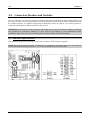
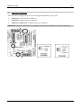
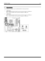
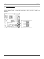
1
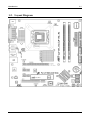
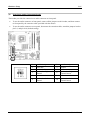
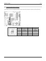
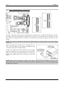
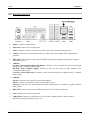
LG-80 Series/LP-80 Series
(LG-80, LG-81, LP-80, LP-81)
Intel Pentium 4 System Board
Socket 775
User’s Manual
4200-0457-01
Rev. 1.00
Copyright and Warranty Notice
The information in this document is subject to change without notice and does not
represent a commitment on part of the vendor, who assumes no liability or responsibility
for any errors that may appear in this manual.
No warranty or representation, either expressed or implied, is made with respect to the
quality, accuracy or fitness for any particular part of this document. In no event shall the
manufacturer be liable for direct, indirect, special, incidental or consequential damages
arising from any defect or error in this manual or product.
Product names appearing in this manual are for identification purpose only and
trademarks and product names or brand names appearing in this document are the
property of their respective owners.
This document contains materials protected under International Copyright Laws. All
rights reserved. No part of this manual may be reproduced, transmitted or transcribed
without the expressed written permission of the manufacturer and authors of this manual.
If you do not properly set the motherboard settings, causing the motherboard to
malfunction or fail, we cannot guarantee any responsibility.
LG-80 Series/LP-80 Series
Table Of Contents
Chapter 1.
1-1.
1-2.
Chapter 2.
2-1.
2-2.
2-3.
2-4.
Introduction ......................................................................... 1-1
Features & Specifications .......................................................................1-1
Layout Diagram ......................................................................................1-3
Hardware Setup................................................................... 2-1
Install The Motherboard..........................................................................2-1
Install CPU, Heatsink and Fan Assembly ...............................................2-2
Install System Memory ...........................................................................2-4
Connectors, Headers and Switches .........................................................2-6
(1). ATX Power Input Connectors .......................................................2-6
(2). FAN Power Connectors.................................................................2-7
(3). CMOS Memory Clearing Header..................................................2-8
(4). Wake-up Header............................................................................2-9
(5). Serial ATA Connectors ................................................................2-10
(6). Front Panel Audio Connection Header........................................2-11
(7). Front Panel Switches & Indicators Headers ................................2-12
(8). Additional IEEE1394 Port Header ..............................................2-13
(9). Additional USB Port Headers .....................................................2-14
(10). Internal Audio Connector ............................................................2-15
(11). Floppy and IDE Disk Drive Connectors .....................................2-16
(12). PCI Express x16 Slot ..................................................................2-17
(13). PCI Express x1 Slot ....................................................................2-17
(14). Back Panel Connectors ...............................................................2-18
Chapter 3.
BIOS Setup .......................................................................... 3-1
Chapter 4.
Driver Installation ............................................................... 4-1
4-1.
Setup Items .............................................................................................4-2
Appendix A.
Troubleshooting (Need Assistance?) .............................................. A-1
Appendix B.
How to Get Technical Support ....................................................... B-1
User’s Manual
LG-80 Series/LP-80 Series
Introduction
1-1
Chapter 1. Introduction
1-1. Features & Specifications
1. CPU
•
•
•
Designed for Intel® 90nm Pentium 4 LGA775 processor with 1066/800 MHz FSB
Supports Intel® Hyper-Threading / XD-bit / EM64T Technology
Enhanced Intel® SpeedStep Technology
2. Chipset
•
•
Intel® 945P / Intel® ICH7 Express Chipset (For models LP-80/LP-81 only)
Intel® 945G / Intel® ICH7 Express Chipset (For models LG-80/LG-81 only)
3. Memory
•
•
•
Two 240-pin DIMM slots
Supports dual channel DDR2 667/533 non-ECC un-buffered memory
Supports maximum memory capacity up to 2GB
4. Graphics Port (For models LG-80/LG-81 only)
•
•
Integrated Intel Graphics Media Accelerator 900 supports DirectX 9
Supports ADD2+ card
5. PCI Express x16 graphic
•
Delivers up to 8GB/s per direction for 3.5 times more bandwidth than AGP8X
6. SATA 3G
•
•
Supports 4 ports Serial ATA 3.0Gb/s data transfer rate
Supports SATA AHCI, providing native command queuing and native hot plug
7. Audio
•
•
Onboard 7.1-channel Intel High Definition Audio CODEC
Supports auto jack sensing and optical S/PDIF Out (For models LP-80/LP-81 only)
8. IEEE 1394 (For models LG-80/LP-80 only)
•
Supports 2 ports IEEE 1394a at 100/200/400 Mb/s transfer rate
9. Gigabit LAN
•
Onboard 10/100/1000M PCI-E controller
10. ABIT Engineered
•
ABIT SoftMenu™ Technology
11. Internal I/O Connectors
•
•
1x PCI-Express x16 slot
2x PCI-Express x1 slots
User’s Manual
1-2
Chapter 1
•
•
•
•
•
•
•
•
1x PCI slot
1x Floppy port supports up to 2.88MB
1x Ultra DMA 100/66/33 IDE connector
4x Serial ATA connectors
2x USB headers
1x IEEE 1394 header (For models LG-80/LP-80 only)
1x FP-Audio header
1x CD-IN header
12. Back Panel I/O
•
•
•
•
•
•
•
•
•
1x PS/2 Keyboard, 1x PS/2 mouse
1x Serial port connector, 1x Parallel port connector
1x AUDIO1 connector (Surround-Left/Surround-Right, Rear-Left/Rear-Right,
Center/Subwoofer)
1x AUDIO2 connector (Mic-In, Line-In, Line-Out)
4x USB connectors
1x RJ-45 LAN connector
1x IEEE 1394 connector (For models LG-80/LP-80 only)
1x VGA connector (For models LG-80/LG-81 only)
1x S/P DIF Out (For models LP-80/LP-81 only)
13. Miscellaneous
•
!
mATX form factor (245mm x 245mm)
Specifications and information contained herein are subject to change without notice.
LG-80 Series/LP-80 Series
Introduction
1-3
1-2. Layout Diagram
User’s Manual
1-4
LG-80 Series/LP-80 Series
Chapter 1
Hardware Setup
2-1
Chapter 2. Hardware Setup
Before the Installation: Turn off the power supply switch (fully turn off the +5V standby power), or
disconnect the power cord before installing or unplugging any connectors or add-on cards. Failing to do
so may cause the motherboard components or add-on cards to malfunction or damaged.
2-1. Install The Motherboard
Most computer chassis have a base with many mounting holes to allow motherboard to be securely
attached on and at the same time, prevented from short circuits. There are two ways to attach the
motherboard to the chassis base:
1. use with studs
2. or use with spacers
In principle, the best way to attach the board is to
use with studs. Only if you are unable to do this
should you attach the board with spacers. Line up
the holes on the board with the mounting holes on
the chassis. If the holes line up and there are
screw holes, you can attach the board with studs.
If the holes line up and there are only slots, you
can only attach with spacers. Take the tip of the
spacers and insert them into the slots. After doing
this to all the slots, you can slide the board into
position aligned with slots. After the board has been positioned, check to make sure everything is OK
before putting the chassis back on.
ATTENTION: To prevent shorting the PCB circuit, please REMOVE the metal studs or spacers if they
are already fastened on the chassis base and are without mounting-holes on the motherboard to align with.
User’s Manual
2-2
Chapter 2
2-2. Install CPU, Heatsink and Fan Assembly
In order to protect the contact pins, please pay
attention to these notices:
1. A maximum 20 cycles of CPU installation
is recommended.
2. Never touch the contact pins with fingers
or any object.
3. Always put on the cap when the CPU is
not in use.
4. Use your right thumb and forefinger to
grasp the CPU package. Be sure to grasp on the
edge of the substrate, and face the Pin-1
indicator toward the bottom-left side. Aim at the
socket and place the CPU package vertical
down into the socket.
1. Place the board so as to let the lever hook
of the socket is on your left side. Use your left
thumb and forefinger to hold the lever hook,
pull it away from the retention tab.
5. Visually inspect if the CPU is seated well
into the socket. The alignment key must be
located in the notch of package.
2.
Rotate the lever to fully open position.
3. Use your right thumb on the bottom-right
side of the load plate and lift it up to fully open
position.
LG-80 Series/LP-80 Series
6. Use your left hand to hold the load plate,
and use your right thumb to peel the cap off.
Hardware Setup
The cap plays an important role in protecting
contact pins. In order to prevent bent pin, PUT
ON the cap after operation or testing.
2-3
For detailed information on how to install your
heatsink and fan assembly, please refer to the
instruction manual came packed with the
heatsink and fan assembly you bought.
7. Lower the plate onto the CPU package.
Engage the load lever while gently pressing
down the load plate.
10. Press each of the four fasteners down into
the mounting holes.
8. Secure the lever with the hook under
retention tab.
11. Rotate the fastener clock-wise to lock the
heatsink and fan assembly into position.
9. Place the heatsink and fan assembly onto
the socket. Align the four fasteners toward the
four mounting holes on the motherboard.
12. Attach the four-pin power plug from the
heatsink and fan assembly to the CPU FAN
connector.
User’s Manual
2-4
Chapter 2
2-3. Install System Memory
This system board provides two 240-pin DDR2 DIMM slots for DDR 667/533 memory modules with
memory expansion size up to 2GB.
Bank
Memory Module
Total Memory
Bank 0, 1 (DIMM1)
256MB, 512MB, 1GB
256MB ~ 1GB
256MB, 512MB, 1GB
256MB ~ 1GB
Bank 2, 3 (DIMM2)
Total System Memory
256MB ~ 2GB
NOTE: Usually there is no hardware or BIOS setup require after adding or removing memory modules,
but you will have to clear the CMOS memory first if any memory module related problem occurs.
LG-80 Series/LP-80 Series
Hardware Setup
2-5
Power off the computer and unplug the AC power cord before installing or removing memory modules.
1.
Locate the DIMM slot on the board.
2.
Hold two edges of the DIMM module
carefully, keep away of touching its
connectors.
3.
Align the notch key on the module with the
rib on the slot.
4.
Firmly press the module into the slots until
the ejector tabs at both sides of the slot
automatically snaps into the mounting notch. Do not force the DIMM module in with extra force as
the DIMM module only fit in one direction.
5.
To remove the DIMM modules, push the two ejector tabs on the slot outward simultaneously, and
then pull out the DIMM module.
ATTENTION: Static electricity can damage the electronic components of the computer or optional
boards. Before starting these procedures, ensure that you are discharged of static electricity by touching a
grounded metal object briefly.
User’s Manual
2-6
Chapter 2
2-4. Connectors, Headers and Switches
Here we will show you all of the connectors, headers and switches, and how to connect them. Please read
the entire section for necessary information before attempting to finish all the hardware installation inside
the computer chassis. A complete enlarged layout diagram is shown in Chapter 1 for all the position of
connectors and headers on the board that you may refer to.
WARNING: Always power off the computer and unplug the AC power cord before adding or removing
any peripheral or component. Failing to so may cause severe damage to your motherboard and/or
peripherals. Plug in the AC power cord only after you have carefully checked everything.
(1).
ATX Power Input Connectors
This motherboard provides two power connectors to connect ATX12V power supplier.
NOTE: This 24-pin power connector “ATXPWR1” is compliant to the former 20-pin type. Pay attention
to the orientation when doing so (Pin-11, 12, 23, and 24 should be left un-connected).
LG-80 Series/LP-80 Series
Hardware Setup
(2).
2-7
FAN Power Connectors
These connectors each provide power to the cooling fans installed in your system.
•
CPUFAN1: CPU Fan Power Connector
•
SYSFAN1: System Fan Power Connector
•
AUXFAN1, AUXFAN2: Auxiliary Fan Power Connector
WARNING: These fan connectors are not jumpers. DO NOT place jumper caps on these connectors.
User’s Manual
2-8
(3).
Chapter 2
CMOS Memory Clearing Header
This header uses a jumper cap to clear the CMOS memory.
•
Pin 1-2 shorted (default): Normal operation.
•
Pin 2-3 shorted: Clear CMOS memory.
WARNING: Turn the power off first (including the +5V standby power) before clearing the CMOS
memory. Failing to do so may cause your system to work abnormally or malfunction.
LG-80 Series/LP-80 Series
Hardware Setup
(4).
2-9
Wake-up Header
These headers use a jumper cap to enable/disable the wake-up function.
•
USB-PWR1:
Pin 1-2 shorted (default): Disable wake-up function support at USB1 port.
Pin 2-3 shorted: Enable wake-up function support at USB1 port.
•
USB-PWR2:
Pin 1-2 shorted (default): Disable wake-up function support at USB2 port.
Pin 2-3 shorted: Enable wake-up function support at USB2 port
User’s Manual
2-10
(5).
Chapter 2
Serial ATA Connectors
These connectors are provided to attach one Serial ATA device at each channel via Serial ATA cable.
For more information on how to configure the function mode for SATA, please refer to the item in the
BIOS menu.
LG-80 Series/LP-80 Series
Hardware Setup
(6).
2-11
Front Panel Audio Connection Header
This header provides the connection to audio connector at front panel.
•
To use the audio connector at front panel, remove all the jumpers on this header, and then connect
to front panel by the extension cable provided with the chassis.
•
To use the audio connector at rear panel, disconnect the extension cable, attach the jumpers back at
pin 5-6, and pin 9-10 (default setting).
Pin
1
3
5
7
9
Pin Assignment
Audio Mic.
Audio Mic. Bias
Speaker Out Right
Channel
X
Speaker Out Left
Channel
Pin
2
4
6
8
10
Pin Assignment
Ground
VCC
Speaker Out Right
Channel Return
NC
Speaker Out Left
Channel Return
User’s Manual
2-12
(7).
Chapter 2
Front Panel Switches & Indicators Headers
This header is used for connecting switches and LED indicators on the chassis front panel.
Watch the power LED pin position and orientation. The mark “+” align to the pin in the figure below
stands for positive polarity for the LED connection. Please pay attention to connect these headers. A
wrong orientation will only cause the LED not lighting, but a wrong connection of the switches could
cause system malfunction.
•
HLED (Pin 1, 3):
Connects to the HDD LED cable of chassis front panel.
•
RST (Pin 5, 7):
Connects to the Reset Switch cable of chassis front panel.
•
SPKR (Pin 13, 15, 17, 19):
Connects to the System Speaker cable of chassis.
•
SLED (Pin 2, 4):
Connects to the Suspend LED cable (if there is one) of chassis front panel.
•
PWR (Pin 6, 8):
Connects to the Power Switch cable of chassis front panel.
•
PLED (Pin 16, 18, 20):
Connects to the Power LED cable of chassis front panel.
LG-80 Series/LP-80 Series
Hardware Setup
2-13
(8). Additional IEEE1394 Port Header
This header provides one additional IEEE1394 port connection through an extension cable and bracket.
Pin
Pin Assignment
Pin
1
TPA0 +
2
Pin Assignment
TPA0 -
3
Ground
4
Ground
5
TPB0 +
6
TPB0 -
7
+12V
8
+12V
9
NC
10
Ground
User’s Manual
2-14
(9).
Chapter 2
Additional USB Port Headers
These headers each provide 2 additional USB 2.0 ports connection through an USB cable designed for
USB 2.0 specifications.
Pin
LG-80 Series/LP-80 Series
Pin Assignment
Pin
Pin Assignment
1
VCC
2
VCC
3
Data0 -
4
Data1 -
5
Data0 +
6
Data1 +
7
Ground
8
Ground
9
NC
10
NC
Hardware Setup
2-15
(10). Internal Audio Connector
This connector connects to the audio output of internal CD-ROM drive or add-on card.
User’s Manual
2-16
Chapter 2
(11). Floppy and IDE Disk Drive Connectors
The FDC1 connector connects up to two floppy drives with a 34-wire, 2-connector floppy cable. Connect
the single end at the longer length of ribbon cable to the FDC1 on the board, the two connectors on the
other end to the floppy disk drives connector. Generally you need only one floppy disk drive in your
system.
NOTE: The red line on the ribbon cable must be aligned with pin-1 on both the FDC1 port and the floppy
connector.
Each of the IDE port connects up to two IDE drives at
Ultra ATA/100 mode by one 40-pin, 80-conductor, and
3-connector Ultra ATA/66 ribbon cables.
Connect the single end (blue connector) at the longer
length of ribbon cable to the IDE port of this board, the
other two ends (gray and black connector) at the shorter
length of the ribbon cable to the connectors of your hard
drives.
NOTE: Make sure to configure the “Master” and “Slave” relation before connecting two drives by one
single ribbon cable. The red line on the ribbon cable must be aligned with pin-1 on both the IDE port and
the hard-drive connector.
LG-80 Series/LP-80 Series
Hardware Setup
2-17
(12). PCI Express x16 Slot
This slot is used to attach the next generation of graphics architecture.
(13). PCI Express x1 Slot
This slot is used to attach the next generation of I/O architecture.
User’s Manual
2-18
Chapter 2
(14). Back Panel Connectors
LP-80/LP-81:
•
Mouse: Connects to PS/2 mouse.
•
Keyboard: Connects to PS/2 keyboard.
•
LPT1: Connects to printer or other devices that support this communication protocol.
•
COM1: Connects to external modem, mouse or other devices that support this communication
protocol.
•
OPT-OUT1: This connector provides an S/PDIF-Out connection through optical fiber to digital
multimedia devices.
AUDIO1:
S.L./S.R. (Surround Left/Surround Right): Connects to the surround left and surround right
channel in the 7.1-channel audio system.
R.L./R.R. (Rear Left/Rear Right): Connects to the rear left and rear right channel in the
7.1-channel audio system.
Cen./Sub. (Center/Subwoofer): Connects to the center and subwoofer channel in the 7.1-channel
audio system.
•
• AUDIO2:
Mic-In: Connects to the plug from external microphone.
Line-In: Connects to the line out from external audio sources.
Line-Out: Connects to the front left and front right channel in the 7.1-channel or regular 2-channel
audio system.
•
IEEE1394: Connects to devices of IEEE1394 protocol. (For model LP-80 only)
•
LAN: Connects to Local Area Network.
•
USB1/USB2: Connects to USB devices such as scanner, digital speakers, monitor, mouse,
keyboard, hub, digital camera, joystick, etc.
LG-80 Series/LP-80 Series
Hardware Setup
2-19
LG-80/LG-81:
•
Mouse: Connects to PS/2 mouse.
•
Keyboard: Connects to PS/2 keyboard.
•
LPT1: Connects to printer or other devices that support this communication protocol.
•
COM1: Connects to external modem, mouse or other devices that support this communication
protocol.
•
VGA1: Connects to monitor input.
•
AUDIO1:
S.L./S.R. (Surround Left/Surround Right): Connects to the surround left and surround right
channel in the 7.1-channel audio system.
R.L./R.R. (Rear Left/Rear Right): Connects to the rear left and rear right channel in the
7.1-channel audio system.
Cen./Sub. (Center/Subwoofer): Connects to the center and subwoofer channel in the 7.1-channel
audio system.
• AUDIO2:
Mic-In: Connects to the plug from external microphone.
Line-In: Connects to the line out from external audio sources.
Line-Out: Connects to the front left and front right channel in the 5.1-channel or regular 2-channel
audio system.
•
IEEE1394: Connects to devices of IEEE1394 protocol. (For model LG-80 only)
•
LAN: Connects to Local Area Network.
•
USB1/USB2: Connects to USB devices such as scanner, digital speakers, monitor, mouse,
keyboard, hub, digital camera, joystick, etc.
User’s Manual
2-20
LG-80 Series/LP-80 Series
Chapter 2
BIOS Setup
3-1
Chapter 3. BIOS Setup
This motherboard provides a programmable EEPROM that you can update the BIOS utility. The BIOS
(Basic Input/Output System) is a program that deals with the basic level of communication between
processor and peripherals. Use the BIOS Setup program only when installing motherboard, reconfiguring
system, or prompted to “Run Setup”. This chapter explains the Setup Utility of BIOS utility.
After powering up the system, the BIOS message appears on the screen, the memory count begins, and
then the following message appears on the screen:
PRESS DEL TO ENTER SETUP
If this message disappears before you respond, restart the system by pressing <Ctrl> + <Alt> + <Del>
keys, or by pressing the Reset button on computer chassis. Only when it failed by these two methods can
you restart the system by powering it off and then back on.
After pressing <Del> key, the main menu screen appears.
NOTE: In order to increase system stability and performance, our engineering staffs are constantly
improving the BIOS menu. The BIOS setup screens and descriptions illustrated in this manual are for
your reference only, and may not completely match with what you see on your screen.
User’s Manual
3-2
LG-80 Series/LP-80 Series
Chapter 3
Driver Installation
4-1
Chapter 4. Driver Installation
All the necessary drivers are included within the Drivers & Utilities CD that came packed with the
motherboard. The display shown in the following figure should appear after inserting the Drivers &
Utilities CD into your CD-ROM drive, if not, enter # [My Computer] # [CD-ROM] Drive # double
click [autorun.exe]. Please follow the on-screen instruction.
User’s Manual
4-2
Chapter 4
4-1. Setup Items
•
Intel Chipset Software Utility
Install the Intel Chipset Software Utility for Windows Operating System.
•
Audio Driver
Install the onboard audio driver for Windows Operating System.
•
VGA Driver
Install the onboard VGA driver for Windows Operating System.
•
LAN Driver
Install the onboard LAN driver for Windows Operating System.
•
USB 2.0 Driver
Update the USB 2.0 driver for Windows 2000/XP Operating System via the Windows Updating
Program.
•
Manual
View the user’s manual in PDF file.
•
Utility
Click to enter the sub-screen for installing software.
•
ABIT Utility
Click to enter the sub-screen to install utilities like Flash Menu (BIOS Update Utility) and
Hardware Doctor.
•
Browse CD
Browse the contents of this CD-ROM.
•
Close
Exit the CD setup Items Menu.
LG-80 Series/LP-80 Series
Troubleshooting (Need Assistance?)
A-1
Appendix A. Troubleshooting (Need Assistance?)
Q & A:
Q: Do I need to clear the CMOS before I use a new motherboard to assemble my new computer
system?
A: Yes, we highly recommend that you clear the CMOS before installing a new motherboard. Please
move the CMOS jumper from its default 1-2 position to 2-3 for a few seconds, and then back. When
you boot up your system for the first time, follow the instructions in the user's manual to load the
optimized defaults.
Q: If my systems hang when I update the BIOS or set the wrong CPU parameters, what should I
do?
A: Whenever you update the BIOS or if the system hangs due to wrong CPU parameters setting, always
clear CMOS jumper before booting up again.
Q: Why the system fails to boot up again right after a mechanical power-off?
A: Please keep a 30-second interval between each mechanical power On/Off.
Q: Why the system failed to boot up and nothing was displayed on the screen after I did some
over-clocking or non-standard settings inside the BIOS? Is the motherboard dead? Do I need to
return it to where I bought from or go through an RMA process?
A: It should not cause hardware or permanent damage to motherboard when BIOS settings were
changed from default to over-clocking or non-standard status.
We suggest the following three troubleshooting methods to discharge CMOS data, recover the
hardware default status, and then make the motherboard working again. No need to bother returning
the motherboard to where you bought from or go through an RMA process.
Step 1. Switch off the power supply unit and then switch it on again after one minute. If there is no
power switch on the power supply unit, disconnect its power cord for one minute and then
connect it back.
Press and hold the <Insert> key on the keyboard, press the power-on button to boot up
system. If it works, loose the <Insert> key and hit <Del> key to enter the BIOS setup page to
do the correct settings.
If the situation remains the same, repeat the procedures in Step 1 for three times, or try Step
2.
Step 2. Switch off the power supply unit or disconnect the power cord. Open the chassis cover.
Locate the CCMOS jumper near the button battery. Change the jumper position from default
1-2 to 2-3 for one minute to discharge the CMOS data, and then put it back to default 1-2
position.
Close the chassis and switch on the power supply unit or plug in the power cord. Press the
power-on button to boot up system. If it works, hit <Del> key to enter the BIOS setup page
to do the correct settings.
If the situation remains the same, try Step 3.
Step 3. The same procedure as Step 2, but in the meantime of discharging the CMOS data, pull out
ATX power connectors from motherboard and remove the button battery during CMOS
discharging.
User’s Manual
A-2
Appendix A
Q: How can I get a quick response to my request for technical support?
A: Be sure to follow the guidelines as stated in the “Technical Support Form” section of this manual.
If you have a problem during operation, in order to help our technical support personnel quickly
determine the problem with your motherboard and give you the answers you need, before filling in
the technical support form, eliminate any peripheral that is not related to the problem, and indicate it
on the form. Fax this form to your dealer or to the company where you bought the hardware in order
to benefit from our technical support. (You can refer to the examples given below)
Example 1:
With a system including: motherboard (with CPU, DRAM, COAST...) HDD, CD-ROM, FDD, VGA
CARD, MPEG CARD, SCSI CARD, SOUND CARD, etc. After the system is assembled, if you
cannot boot up, check the key components of the system using the procedure described below. First
remove all interface cards except the VGA card and try to reboot.
If you still cannot boot up: Try installing another brand/model VGA card and see if the system will
start. If it still does not start, note the VGA card model, motherboard model, Bios identification
number, CPU on the technical support form (refer to main instructions), and describe the problem in
the problem description space provided.
If you can boot up: Insert the interface cards you have removed back into the system, one by one
and try to start the system each time you insert a card, until the system will not start. Keep the VGA
card and the interface card that caused the problem inserted on the motherboard, remove any other
cards or peripheral, and start again. If you still cannot start, note the information related to both cards
in the add-on Card space provided, and don’t forget to indicate the motherboard model, version,
BIOS identification number, CPU (refer to main instructions), and give a description of the problem.
Example 2:
With a system including the motherboard (with CPU, DRAM, COAST...) HDD, CD-ROM, FDD,
VGA CARD, LAN CARD, MPEG CARD, SCSI CARD, SOUND CARD, after assembly and after
having installed the Sound Card Driver, when you restart the system, when it runs the Sound Card
Driver, it resets automatically. This problem may be due to the Sound Card Driver. During the
Starting DOS… procedure, press SHIFT (BY-PASS) key, to skip CONFIG.SYS and
AUTOEXEC.BAT; edit CONFIG.SYS with a text editor, and in function the line that loads the
Sound Card Driver, add a remark REM, in order to disable the Sound Card Driver. See the example
below.
CONFIG.SYS:
DEVICE=C:\DOS\HIMEM.SYS
DEVICE=C:\DOS\EMM386.EXE HIGHSCAN
DOS=HIGH, UMB
FILES=40
BUFFERS=36
REM DEVICEHIGH=C:\PLUGPLAY\DWCFGMG.SYS
LASTDRIVE=Z
Restart the system. If the system starts and does not reset, you can be sure that the problem is due to
the Sound Card Driver. Write down the Sound Card model, motherboard model, BIOS identification
number on the technical support file (refer to main instructions), and describe the problem in the
space provided.
We will show you how to fill the “Technical Support Form”.
LG-80 Series/LP-80 Series
Troubleshooting (Need Assistance?)
A-3
Main instructions:
To fill in this “Technical Support Form”, refer to the step-by-step instructions given below:
1*. MODEL: Note the model number given in your user’s manual.
Example: LG-80, LG-81, LP-80, LP-81
*
2 . Motherboard model number (REV): Note the motherboard model number labeled on the
motherboard as “REV:*.**”.
Example: REV: 1.00
*
3 . BIOS ID and Part Number: See the on screen message.
4.
DRIVER REV: Note the driver
version number indicated on the
DEVICE DRIVER disk (if any) as
“Release *.**”. For example:
5*. OS/APPLICATION: Indicate the
operating system and applications
you are running on the system.
Example: MS-DOS® 6.22,
Windows® 98 SE, Windows® 2000, etc....
6*. CPU: Indicate the brand and the speed (MHz) of your CPU.
Example:(A) In the “Brand” space, write “Intel”; in the “Specifications” space, write “Pentium® 4
1.9GHz”.
7.
HDD: Indicate the brand and specifications of your HDD(s); specify if the HDD is using $IDE1 or
$IDE2. If you know the disk capacity, indicate it and check (“%”) “ ”; in case you give no
indication, we will consider that your HDD is “&IDE1” Master.
Example: In the “HDD” space, check the box; in the Brand space, write “Seagate”; in the
Specifications space, write “ST31621A (1.6GB)”.
8.
CD-ROM Drive: Indicate the brand and specifications of your CD-ROM drive. Specify if it uses $
IDE1 or $IDE2, and check (“%”) “ ”; in case you give no indication, we will consider that your
CD-ROM is “&IDE2” Master.
Example: In the “CD-ROM drive” space, check the box, in the Brand space, write “Mitsumi”, in the
Specifications space, write “FX-400D”.
9.
System Memory (DDR SDRAM): Indicate the brand and specifications (DDR DIMM) of your
system memory. Such as Density, Description, Module Components, Module Part Number, CAS
Latency, and Speed (MHz).
For example: In the Brand space, write “Micron”; in the Specifications space, write: Density:
128MB, Description: SS 16 Megx72 2.5V ECC Gold, Module Components: (9) 16 Megx 8,
Module Part Number: MT9VDDT1672AG, CAS Latency: 2, Speed (MHz): 200 MHz.
Please give us the detailed information of your DDR SDRAM module; it will help us to simulate the
problems you met.
10. ADD-ON CARD: Indicate which add-on cards you are absolutely sure are related to the problem.
If you cannot identify the problem’s origin, indicate all the add-on cards inserted into your system.
NOTE: Items between the “*” are absolutely necessary.
User’s Manual
A-4
Appendix A
'
Technical Support Form
! Company Name:
( Phone Number:
" Contact Person:
# Fax Number:
) E-mail Address:
Model
*
Motherboard Model No.
DRIVER REV
OS/Application
*
Hardware Name
Brand
CPU
HDD
CD-ROM-Drive
*
IDE1
IDE2
IDE1
IDE2
System Memory
ADD-ON CARD
Problem Description:
LG-80 Series/LP-80 Series
BIOS ID #
Specifications
*
How to Get Technical Support
B-1
Appendix B. How to Get Technical Support
(From our website) http://www.abit.com.tw
(In North America) http://www.abit-usa.com
(In Europe) http://www.abit.nl
Thank you for choosing ABIT products. ABIT sells all our products through distributors,
resellers and system integrators; we have no direct sales to end-users. Before sending email
for tech support please check with your resellers or integrators if you need any services, they
are the ones who sold you your system and they should know best as to what can be done,
how they serve you is a good reference for future purchases.
We appreciate every customer and would like to provide the best service to you. Providing
fast service to our customers is our top priority. However we receive many phone calls and a
huge amount of email from all over the world. At the present time it is impossible for us to
respond to every single inquiry. Therefore it is quite possible that if you send an email to us
that you may not receive a response.
We have done many compatibility tests and reliability tests to make sure our products have
the best quality and compatibility. In case you need service or technical support, please
understand the constraint we have and always check with the reseller who sold the product
to you first.
To expedite service, we recommend that you follow the procedures outlined below before
contacting us. With your help, we can meet our commitment to provide the best service to the
greatest number of ABIT customers:
1. Check the Manual. It sounds simple but we have taken a lot of care in making a
well-written and thorough manual. It is full of information that doesn't only pertain to
motherboards. The CD-ROM included with your board will have the manual as well as
drivers. If you don't have either one, go to our Program Download Area of the Website or
FTP server.
2. Download latest BIOS, software or drivers. Please go to our Program Download area
on our Website to check to see if you have the latest BIOS. They are developed over
periods of time to fixes bugs or incompatibilities. Also please make sure you have the
latest drivers from your peripheral cards makers!
3. Check the ABIT Technical Terms Guide and FAQ on our Website. We are trying to
expand and make the FAQs more helpful and information rich. Let us know if you have
any suggestions. For hot topics, check out our HOT FAQ!
User’s Manual
B-2
Appendix B
4. Internet Newsgroups. They are a great source of information and many people there can
offer help. ABIT's Internet News group, alt.comp.periphs.mainboard.abit, is an ideal
forum for the public to exchange information and discuss experiences they have had with
ABIT products. Many times you will see that your question has already been asked before.
This is a public Internet news group and it is reserved for free discussions. Here is a list of
some of the more popular ones:
alt.comp.periphs.mainboard.abit
comp.sys.ibm.pc.hardware.chips
alt.comp.hardware.overclocking
alt.comp.hardware.homebuilt
alt.comp.hardware.pc-homebuilt
5. Ask your reseller. Your ABIT authorized distributor should be able to provide the fastest
solution to your technical problem. We sell our products through distributors who sell to
resellers and stores. Your reseller should be very familiar with your system configuration
and should be able to solve your problem much more efficiently than we could. After all,
your reseller regards you as an important customer who may purchase more products and
who can urge your friends to buy from him or her as well. They integrated and sold the
system to you. They should know best what your system configuration is and your
problem. They should have reasonable return or refund policies. How they serve you is
also a good reference for your next purchase.
6. Contacting ABIT. If you feel that you need to contact ABIT directly you can send email
to the ABIT technical support department. First, please contact the support team for the
branch office closest to you. They will be more familiar with local conditions and
problems and will have better insight as to which resellers offer what products and
services. Due to the huge number of emails coming in every day and other reasons, such
as the time required for problem reproduction, we will not be able to reply to every email.
Please understand that we are selling through distribution channels and don't have the
resources to serve every end-user. However, we will try to do our best to help every
customer. Please also remember that for many of our technical support team English is a
second language, you will have a better chance of getting a helpful answer if your
question can be understood in the first place. Be sure to use very, simple, concise
language that clearly states the problem, avoid rambling or flowery language and always
list your system components. Here is the contact information for our branch offices:
7. RMA Service. If your system has been working but it just stopped, but you have not
installed any new software or hardware recently, it is likely that you have a defective
component. Please contact the reseller from whom you bought the product. You should be
able to get RMA service there.
LG-80 Series/LP-80 Series
How to Get Technical Support
North America and
South America
B-3
ABIT Computer (U.S.A.) Corporation
45531 Northport Loop West,
Fremont CA, 94538, U.S.A.
Tel: 1-510-623-0500
Fax: 1-510-623-1092
Sales: [email protected]
Latin America Sales: [email protected]
Marketing: [email protected]
Web Site: http://www.abit-usa.com
RMA Center: http://rma.abit-usa.com
UK and Ireland
Germany and Benelux (Belgium,
Netherlands, Luxembourg),
France, Italy, Spain, Portugal,
Greece, Denmark, Norway,
Sweden, Finland, and
Switzerland
Austria, Czech, Romania,
Bulgaria, Slovakia, Croatia,
Bosnia, Serbia, and Macedonia
Shanghai
Russia and CIS
ABIT Computer (U.K.) Corporation Ltd.
Unit 3, 24-26 Boulton Road, Stevenage,
Herts SG1 4QX, UK
Tel: 44-1438-228888
Fax: 44-1438-226333
E-mail: [email protected]
AMOR Computer B.V. (ABIT's European Office)
Jan van Riebeeckweg 15, 5928LG, Venlo,
The Netherlands
Tel: 31-77-3204428
Fax: 31-77-3204420
Sales: [email protected]
Web Site: http://www.abit.nl
Asguard Computer Ges.m.b.H
Schmalbachstrasse 5,
A-2201 Gerasdorf / Wien, Austria
Tel: 43-1-7346709
Fax: 43-1-7346713
E-mail: [email protected]
ABIT Computer (Shanghai) Co. Ltd.
Tel: 86-21-6235-1829
Fax: 86-21-6235-1832
Web Site: http://www.abit.com.cn
ABIT Computer (Russia) Co. Ltd.
Sales: [email protected]
Info: [email protected]
Web Site: http://www.abit.ru
User’s Manual
B-4
Appendix B
Poland
Japan
Taiwan Head Office
(Serving all other territories
not listed above.
Taiwan is 8+ GMT time,
and may have different holiday
calendar from yours.)
ABIT Computer (Poland) Co. Ltd.
Przedstawicielstwo w Polsce ul. Wita Stwosza 28,
50-149 Wrocław
Tel: 48 71 780 78 65 / 66
Fax: 48 71 372 30 87
Web Site: http://www.abit4u.jp
ABIT Computer Corporation
No. 323, Yang Guang St.,
Neihu, Taipei, 114, Taiwan
Tel: 886-2-8751-8888
Fax: 886-2-8751-3382
Sales: [email protected]
Marketing: [email protected]
Web Site: http://www.abit.com.tw
8. Reporting Compatibility Problems to ABIT. Because of tremendous number of email
messages we receive every day, we are forced to give greater weight to certain types of
messages than to others. For this reason, any compatibility problem that is reported to us,
giving detailed system configuration information and error symptoms will receive the
highest priority. For the other questions, we regret that we may not be able to reply
directly. But your questions may be posted to the Internet news group in order that a
larger number of users can have the benefit of the information. Please check the news
group from time to time.
Thank You
ABIT Computer Corporation
http://www.abit.com.tw
LG-80 Series/LP-80 Series