1
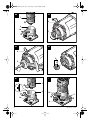
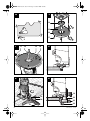
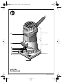
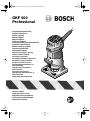
2 609 140 541.book Seite 1 Dienstag, 22. Januar 2008 8:46 08
GKF 600
Professional
Originalbetriebsanleitung
Original instructions
Notice originale
Manual original
Manual original
Istruzioni originali
Oorspronkelijke gebruiksaanwijzing
Original brugsanvisning
Bruksanvisning i original
Original driftsinstruks
Alkuperäiset ohjeet
Πρωττυπο οδηγιών χρήσης
Orijinal iµletme talimat∂
Instrukcjå oryginalnå
PÛvodním návodem k pouÏívání
Pôvodn˘ návod na pouÏitie
Eredeti használati utasítás
Подлинник руководства по
эксплуатации
Оригінальна інструкція з
експлуатації
Instrucøiuni de folosire
Оригинално ръководство за
експлоатация
Originalno uputstvo za rad
Izvirna navodila
Originalne upute za rad
Algupärane kasutusjuhend
Instrukcijām oriinālvalodā
Originali instrukcija
2 609 140 541.book Seite 3 Dienstag, 22. Januar 2008 8:46 08
A
B
1
1
2
9
2
10
5
1
2
C
D
9
5
5
13
4
12
E
F
1
1
2
2
2
10
3
1
10
3
8
3
2 609 140 541 • 22.1.08
2 609 140 541.book Seite 4 Dienstag, 22. Januar 2008 8:46 08
G
H
14
2
3
15
4
16
17
4
I
17
18
14
16
L
1
K
M
19
19
20
21
4
22
23
24
2 609 140 541 • 22.1.08
2 609 140 541.book Seite 5 Dienstag, 22. Januar 2008 8:46 08
N
O
1
25
3
1
1
2
2
2
26
10
10
P
Q
26
27
26
28
27
R
29
30
31
32
5
2 609 140 541 • 22.1.08
2 609 140 541.book Seite 6 Dienstag, 22. Januar 2008 8:46 08
1
11
10
2
9
8
7
6
5
3
4
GKF 600
Professional
6
2 609 140 541 • 22.1.08
2 609 140 541.book Seite 14 Dienstag, 22. Januar 2008 8:46 08
Tool Specifications
Laminate trimmer
Article number
Rated power input
No-load speed
Tool holder
Weight according to
EPTA-Procedure
01/2003
Protection class
Declaration of Conformity
GKF 600
Professional
3 601 F0A 1..
[W]
600
[rpm] 33 000
6 mm/
8 mm/
1
/ 4" (only UK)
We declare under our sole responsibility that the
product described under „Technical data“ is in
conformity with the following standards or standardization documents: EN 60745 according to
the provisions of the directives 2004/108/EC,
98/37/EC (until 28 Dec 2009), 2006/42/EC (from
29 Dec 2009).
Technical documents at:
Robert Bosch GmbH, PT/ESC,
D-70745 Leinfelden-Echterdingen
[kg]
Dr. Egbert Schneider
Senior Vice President
Engineering
1.5
/ II
Please observe the article number on the type plate of
your machine. The trade names of the individual machines may vary.
The values given are valid for nominal voltages [U] of
230/240 V. For lower voltages and models for specific
countries, these values can vary.
Noise/Vibration Information
Measured values determined according to
EN 60 745.
Typically the A-weighted noise levels of the machine are: sound pressure level 84 dB (A);
sound power level 95 dB (A).
Uncertainty K = 3 dB.
Wear hearing protection!
Overall vibrational values (vector sum of three
directions) determined according to EN 60745:
Vibrational emission value ah =4.5 m/s2, uncertainty K=1.5 m/s2.
WARNING The vibration emission level
given in this information sheet
has been measured in accordance with a standardised test given in EN 60745 and may be
used to compare one tool with another.
The vibration emission level will vary because of
the ways in which a power tool can be used and
may increase above the level given in this information sheet. This could lead to a significant underestimate of exposure when the tool is used
regularly in such a way.
NOTE: To be accurate, an estimation of the
level of exposure to vibration experienced during a given period of work should also take into
account the times when the tool is switched off
and when it is running but not actually doing the
job. This may significantly reduce the exposure
level over the total working period.
14 | English
Dr. Eckerhard Strötgen
Head of Product
Certification
03.12.2007, Robert Bosch GmbH, Power Tools Division
D-70745 Leinfelden-Echterdingen
Product Features
While reading the operating instructions, unfold
the graphics page for the machine and leave it
open.
The numbering of the product features refers to
the illustration of the machine on the graphics
page.
1 Motor unit
2 Routing base
3 Thumbwheel for depth-of-cut fine
adjustment
4 Router bit*
5 Collet chuck
6 Guide plate
7 Base plate
8 Scale for depth-of-cut adjustment
9 Spindle lock button
10 Clamping lever
11 On/Off switch
12 Open-end spanner
13 Collet
14 Guide bushing*
15 Rubber ring
16 Guide plate, round*
17 Fastening screw for base plate (4 x)
18 Centring pin*
19 Knurled screw for attachment of side stop
20 Parallel guide
2 609 140 541 • 22.1.08
2 609 140 541.book Seite 15 Dienstag, 22. Januar 2008 8:46 08
21 Wing bolt for parallel guide
22 Roller guide
23 Wing bolt for horizontal alignment of the
roller guide
24 Wing bolt for locking of the horizontal
alignment
25 Base cover sleeve*
26 Tilt base*
27 Wing bolt for angle adjustment
28 Scale for routing angle adjustment
29 Handle*
30 Extraction hood*
31 Extraction adapter*
32 Side-handle subbase*
* Illustrated or described accessories are not included
as standard delivery.
For Your Safety
Read all safety warnings and all
instructions. Failure to follow the
warnings and instructions may result in electric shock, fire and/or serious injury.
Save all warnings and instructions for future
reference.
Additionally, the general safety instructions either in the enclosed booklet or those added in
the centre of these operating instructions must
be observed.
■ The allowable speed of the tool insert
must be at least as high as the maximum
speed stated on the machine. Accessories
driven in excess of their allowable speed can
be destroyed.
■ Routing tools or other tool inserts must fit
exactly in the tool holder (collet) of your
machine. Tool inserts that do not fit precisely
in the tool holder of the machine rotate irregularly, vibrate heavily and can lead to loss of
control.
■ Guide the machine against the workpiece
only when it is switched on. Otherwise
there may be danger of kickback when the
tool insert jams in the workpiece.
2 609 140 541 • 22.1.08
■ Keep your hands away from the routing
area and the routing tool. Hold the auxiliary handle or the motor housing with
your second hand. When both hands hold
the machine, they cannot be injured by the
routing tool.
■ Never cut over metal objects, nails or
screws. The routing tool can become damaged and lead to increased vibrations.
■ Hold the power tool only by the insulated
gripping surfaces when performing an operation where the cutting tool may contact
hidden wiring or its own power cord. Contact with a “live” wire will also make exposed
metal parts of the power tool “live” and shock
the operator.
■ Use suitable detectors to determine if utility lines are hidden in the work area or call
the local utility company for assistance.
Contact with electric lines can lead to fire and
electric shock. Damaging a gas line can lead
to explosion. Penetrating a water line causes
property damage or may cause an electric
shock.
■ Do not use dull or damaged router bits.
Dull or damaged router bits cause increased
friction, can become jammed and lead to imbalance.
■ Secure the workpiece. A workpiece
clamped with clamping devices or in a vice is
held more securely than by hand.
■ Do not work materials containing asbestos. Asbestos is considered carcinogenic.
■ Take protective measures when dust can
develop during working that is harmful to
one’s health, combustible or explosive.
Example: Some dusts are regarded as carcinogenic. Wear a dust mask and work with
dust/chip extraction when connectable.
■ Always wait until the machine has come to
a complete stop before placing it down.
The tool insert can jam and lead to loss of
control over the power tool.
■ Do not use a machine with a damaged
mains cable. Do not touch the damaged
cable and pull the mains plug when the cable is damaged while working. Damaged
cables increase the risk of an electric shock.
English | 15
2 609 140 541.book Seite 16 Dienstag, 22. Januar 2008 8:46 08
Intended Use
The machine is intended for trimming edges in
wood, plastic and light building materials. It is
also suitable for routing of grooves, profiles and
slots as well as for contour routing.
Mounting
■ Before any work on the machine itself, pull
the mains plug.
Disassembling the Motor Unit
(see figure A )
For disassembly of the motor unit 1, open the
clamping lever 10 and turn the routing base 2 so
that the “▲” mark is in line with the “ ” symbol
on the motor unit. Then pull the motor unit 1 upward to the stop, turn the motor unit 1 in anticlockwise direction to the stop and pull the motor unit 1 out of the routing base 2.
Router Bit Selection
Depending on processing and application,
router bits are available in the most different designs and qualities:
Router bits made of high speed steel (HSS)
are suitable for the machining of soft materials,
e. g., softwood and plastic.
Carbide tipped router bits (HM) are especially
suitable for hard and abrasive materials, e. g.,
hard wood.
Original router bits from the extensive Bosch accessories program are available at your specialist shop.
Inserting Router Bits
(see figures B + C )
■ Before any work on the machine itself, pull
the mains plug.
■ It is recommended to wear protective gloves
when inserting or replacing router bits.
Disassemble the motor unit as described in the
respective section.
Press the spindle lock button 9 and keep it
pressed. Possibly turn the spindle by hand until
the lock engages.
■ Press the spindle lock button only when at a
standstill.
Loosen the collet chuck 5 with an open-end
spanner 12 (size 18 mm) several turns, but do
not unscrew the tightening nut.
16 | English
Insert the shank of the router bit at least 20 mm
(shank length) into the collet.
Tighten the collet chuck 5 with the open-end
spanner 12 (size 18 mm) and release the spindle lock button 9.
Do not tighten the tightening nut of the
collet chuck without a router bit inserted.
Replacing the Collet (see figure
D
)
Depending on the routing tool to be used, different collets can be inserted, see “Tool Specifications”.
The collet 13 must have somewhat play when
seated in the tightening nut. The collet chuck 5
(tightening nut with collet) must assemble easily. Should the collet chuck 5 be damaged, replace immediately.
Press the spindle lock button 9 and keep it
pressed. Possibly turn the spindle by hand until
the lock engages.
Unscrew the collet chuck 5.
Release the spindle lock button 9.
Clean the tool holding fixture and the collet 13
using a soft brush or by blowing out with compressed air.
Tighten the collet chuck 5 again.
Do not tighten the tightening nut of the
collet chuck without a router bit inserted.
Mounting the Motor Unit
(see figure E )
To mount the motor unit 1, open the clamping
lever 10 and bring the two double arrows on the
motor unit 1 and the routing base 2 into alignment. Push the drive unit 1 into the routing
base 2 and turn the motor unit 1 in clockwise direction until the “▲” mark on the routing base 2
points against the line below the “ ” symbol
on the motor unit 1. Push the drive unit 1 into the
routing base 2.
After mounting is completed, position the
“▲” mark of the routing base 2 in line with the
“ ” symbol on the motor unit 1 and lock the
clamping lever 10.
■ After mounting, always check if the motor unit
is seated tightly in the routing base. The pretension of the clamping lever can be changed
by readjusting the nut.
2 609 140 541 • 22.1.08
2 609 140 541.book Seite 17 Dienstag, 22. Januar 2008 8:46 08
Readjusting the Clamping Lever
To readjust the tightening tension, open the
clamping lever 10, turn the nut of the clamping
lever approx. 45° in clockwise direction using an
open-end spanner and then lock the clamping
lever 10 again. Check if the motor unit 1 is
clamped securely. Do not over tighten the nut.
Starting Operation
Observe correct mains voltage: The voltage
of the power source must agree with the voltage
specified on the nameplate of the machine.
Equipment marked with 230 V can also be connected to 220 V.
Switching On and Off
To start the machine, set the On/Off switch 11
to I.
To switch off the machine, set the On/Off
switch 11 to 0.
Setting the Depth-of-cut
(see figure F )
■ The adjustment of the depth-of-cut may only
be carried out when the trimmer is switched
off.
Place the trimmer on the workpiece to be
worked.
Open the clamping lever 10, set the “▲” mark
on the routing base 2 to the “ ” symbol and
slowly lower the motor unit until the router
touches the workpiece. Fix the motor unit in this
position by locking the clamping lever 10.
Read the measuring value off the scale 8 and
note it down (zeroing). Add the desired depth-ofcut to this value.
Open the clamping lever 10 and set the motor
unit to the calculated scale value. Set the
“▲” mark on the routing base 2 to the “ ” symbol and lock the clamping lever 10 again.
Check the carried out depth-of-cut adjustment
with a trial cut and correct it, if necessary.
For fine adjustment of the depth-of-cut, set the
“▲” mark on the motor unit to the “ ” symbol
with the clamping lever 10 open. Adjust the desired depth-of-cut with the thumbwheel 3. Afterwards, lock the clamping lever 10 to securely
lock the motor unit in the routing base.
2 609 140 541 • 22.1.08
Operating Instructions
Direction of Feed (see figure
G
)
The feed motion of the router must always be
carried out against the rotation direction of the
router bit (up-grinding).
When routing in the rotation direction of the
router bit (down-cutting), the machine can break
loose, eliminating control by the user.
Routing Process
■ Use the machine only with the routing
base mounted. Loss of control over the machine can cause injuries.
■ Before beginning the routing procedure,
check if the “▲” mark on the routing base 2 is
positioned in line with the “ ” symbol on the
motor unit 1.
Note: Take into consideration that the router
bit 4 always extends out of the base plate 7. Do
not damage the template or the workpiece.
Adjust the depth-of-cut as described previously.
Switch the machine on and guide it to the location subject to working.
Carry out the routing procedure applying uniform feed.
Switch the machine off after finishing the routing
process. Do not place the power tool down until
after the router bit has come to a complete stop.
Routing with Guide Bushing
The guide bushing 14 enables template and
pattern routing on workpieces.
Inserting guide bushing 14 (see figure H )
Unscrew the four fastening screws on the bottom side of the guide plate 6 and remove the
guide plate 6. Insert the rubber ring 15 and then
the guide bushing 14 into the round guide
plate 16 as shown in the figure. Screw the round
guide plate 16 to the base plate 7 with the countersunk screws provided.
Adjusting/centring the guide bushing
(see figure I )
To ensure that the distance from router bit centre and guide bushing edge is uniform, the guide
bushing and the guide plate can be adjusted to
each other, if required.
Loosen the fastening screws 17 by approx.
2 turns so that the round guide plate 16 can be
moved freely.
English | 17
2 609 140 541.book Seite 18 Dienstag, 22. Januar 2008 8:46 08
Insert the centring pin 18 into the tool holder as
shown in the figure. Hand-tighten the tightening
nut so that the centring pin can still be moved.
Align the centring pin 18 and the guide bushing 14 by lightly moving the round guide
plate 16.
Tighten the fastening screws 17 again and remove the centring pin 18 from the tool holder.
Routing Process
Select a router bit with a smaller diameter than the inside diameter of the
guide bushing.
Place the machine with the guide bushing 14
against the template.
Guide the machine with projecting guide bushing along the template, applying light sideward
pressure.
Note: The template must have a minimum thickness of 8 mm, due to the projecting height of the
guide bushing.
Guide the machine with uniform feed and sideward pressure against the parallel guide 20
alongside the workpiece edge.
Routing with the Roller Guide
(see figure M )
The roller guide 22 is used for routing edges
with router bits without pilot or ball bearing.
Fasten the roller guide 22 to the routing base
with the knurled screw 19.
Guide the machine with uniform feed alongside
the workpiece edge.
Lateral Clearance
In order to change the amount of material removal, the lateral clearance between workpiece
and the guide roller of the roller guide can be adjusted.
Loosen wing bolt 24, adjust the desired lateral
clearance by turning wing bolt 23 and tighten
wing bolt 24 again.
Height
Adjust the vertical alignment of the roller guide
depending on the router bit in use and the thickness of the material to be worked.
Loosen the knurled screw 19 on the roller guide,
slide the roller guide to the desired position and
tighten the knurled screw again.
Assembling the Base Cover Sleeve
(see figure N )
Shaping or Molding Applications
(see figure K )
For shaping or molding applications without the
use of a parallel guide, the router must be
equipped with a pilot or a ball bearing.
Guide the machine from the side to the workpiece until the pilot or the ball bearing of the trimmer faces against the workpiece edge to be
worked. Guide the machine alongside the edge
of the workpiece, ensuring rectangular support.
Excessive pressure can damage the edge of the
workpiece.
Routing with Parallel Guide
(see figure L )
Fasten the parallel guide 20 to the routing base
with the knurled screw 19.
Adjust the desired depth setting on the parallel
guide with wing bolt 21.
18 | English
For assembly of the base cover sleeve 25, remove the clamping lever 10. Place the base
cover sleeve 25 onto the routing base 2 from
above and reassemble the clamping lever 10
again in such a manner that the motor unit 1 is
held securely in the routing base when the
clamping lever is locked.
Routing with Tilt Base
(see figures O – Q )
The tilt base 26 is particularly suitable for flush
routing of laminated edges at hard to reach locations, for routing special angles as well as for
bevelling edges.
When bevelling edges using the tilt base 26, the
router bit must be equipped with a pilot or a ball
bearing.
The tilt base is mounted according to the instructions for the routing base 2.
To achieve precise angles, the tilt base 26 is
equipped with adjustment notches in steps of
7.5°. The complete adjustment range is 75°; the
tilt base inclines to 45° toward the front and 30°
2 609 140 541 • 22.1.08
2 609 140 541.book Seite 19 Dienstag, 22. Januar 2008 8:46 08
toward the rear. Loosen both wing bolts 27 to
adjust the angle. Adjust the desired angle using
the scale 28 and tighten wing bolts 27 again.
Routing with the Side-handle
Subbase (see figure R )
The side-handle subbase 32 can be mounted in
place of guide plate 6. It offers an additional
handle 29 as well as a connection possibility for
dust extraction.
Unscrew the four fastening screws on the bottom side of the guide plate 6 and remove the
guide plate. Screw the side-handle subbase 32
to the base plate as shown in the figure using
the countersunk screws provided.
To connect dust extraction, screw the extraction
adapter 31 to the side-handle subbase 32 with
the two screws. Connect an extraction hose with
a diameter of 19/35 mm to the extraction
adapter 31.
To ensure optimum dust extraction, the extraction adapter 31 should be cleaned regularly.
For working edges, additionally use the extraction hood 30. Mount the extraction hood as
shown in the figure.
For working smooth face surfaces, remove the
extraction hood 30.
The machine can be plugged directly into the receptacle of a Bosch all-purpose vacuum cleaner
with remote starting control. The vacuum
cleaner starts automatically when the machine
is switched on.
The vacuum cleaner must be suitable for the
material to be worked.
When vacuuming dry dust that is especially detrimental to health or carcinogenic, use a special
vacuum cleaner.
Maintenance and Cleaning
■ Before any work on the machine itself, pull
the mains plug.
■ For safe and proper working, always keep the
machine and its ventilation slots clean.
If the machine should fail despite the care taken
in manufacturing and testing procedures, repair
should be carried out by an authorized aftersales service agent for Bosch power tools.
In all correspondence and spare parts orders,
please always include the 10-digit article
number given on the nameplate of the machine.
WARNING! Important instructions for connecting a new 3-pin plug to the 2-wire cable.
2 609 140 541 • 22.1.08
The wires in the cable are coloured according to
the following code:
strain relief
live = brown
neutral = blue
To be fitted
by qualified
professional only
Do not connect the blue or brown wire to the
earth terminal of the plug.
Important: If for any reason the moulded plug is
removed from the cable of this machine, it must
be disposed of safely.
Disposal
Power tools, accessories and packaging should
be sorted for environmental-friendly recycling.
Only for EC countries:
Do not dispose of power tools into
household waste!
According to the European Directive 2002/96/EC on waste electrical and electronic equipment and
its incorporation into national law,
power tools that are no longer suitable for use
must be separately collected and sent for recovery in an environmental-friendly manner.
After-Sales Service and Customer
Assistance
Our after-sales service responds to your questions concerning maintenance and repair of your
product as well as spare parts. Exploded views
and information on spare parts can also be
found under:
www.bosch-pt.com
Our customer consultants answer your questions concerning best buy, application and adjustment of products and accessories.
Great Britain
Robert Bosch Ltd. (B.S.C.)
P.O. Box 98
Broadwater Park
North Orbital Road
Denham
Uxbridge
UB 9 5HJ
Tel. Service: +44 (0844) 736 0109
Fax: +44 (0844) 736 0146
E-Mail: [email protected]
English | 19
2 609 140 541.book Seite 20 Dienstag, 22. Januar 2008 8:46 08
Ireland
Origo Ltd.
Unit 23 Magna Drive
Magna Business Park
City West
Dublin 24
Tel. Service: +353 (01) 4 66 67 00
Fax: +353 (01) 4 66 68 88
Australia, New Zealand and Pacific Islands
Robert Bosch Australia Pty.Ltd.
Power Tools
Locked Bag 66
Clayton South VIC 3169
Customer Contact Center
Inside Australia:
Phone: +61 (01300) 307 044
Fax: + 61 (01300) 307 045
Inside New Zealand:
Phone: +64 (0800) 543 353
Fax: +64 (0800) 428 570
Outside AU and NZ:
Phone: +61 (03) 9541 5555
www.bosch.com.au
Subject to change without notice
20 | English
2 609 140 541 • 22.1.08