1
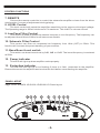
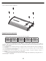
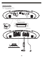
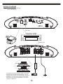
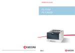
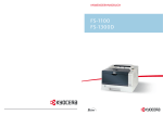
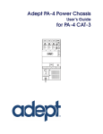
S550.1D
S850.1D
S1300.1D
S2000.1D
FEATURES
l
DOUBLE SIDE PCB AND SMD COMPONENTS.
l
FULL MOSFET DESIGN.
l
LPF AND SUBSONIC CROSSOVER.
l
ADJUSTABLE BASSBOOST LEVEL.
l
ACTIVE X-OVER FUNCTION.
l
HEAVY-DUTY ALUMINUM ALLOY HEATSINK.
l
HIGH (Speaker) OR LOW (RCA) LEVEL INPUTS.
l
OVERLOAD, OVERHEAT, HIGH/LOW VOLTAGE PROTECTION.
l
ROHS COMPLIANT.
CONTROL FUNCTIONS
1. SPEAKERS
Connect speakers/subwoofers to these terminals. Be sure to check wire for proper
polarity. Never connect the speaker cables to chassis ground.
2. +12 Volt Power
Connect this terminal through a FUSE or CIRCUIT BREAKER to the positive terminal of
the vehicle battery or the positive terminal of an isolated audio system battery.
Warning: Always protect this power cable by installing a fuse or circuit breaker of the
appropriate size within 18 inches (45cm) of the battery terminal connection.
3.Remote Turn On
This terminal turns on the amplifier when (+)12 volt is applied to it . Connect it to the
remote turn on lead of the head unit or signal source.
4.GND
Connect this cable directly to the frame of the vehicle. Make sure the metal frame has
been stripped of all paint down to the bare metal. Use the shortest distance possible. It is
always a good idea to replace the factory ground at this time with a larger cable equal to the
new amplifier power cable or larger. CAUTION: Do not connect this terminal directly to the
vehicle battery ground terminal or any other factory ground points.
5. RCA input jacks
These RCA input jacks are for use with source units that have RCA outputs. A source unit
with a minimum level of 200mV is required for proper operation. The use of high quality
twisted pair cables is recommended to decrease the possibility of radiated noise entering the
system.
6. High level inputs
The high level inputs are for use with speaker level wiring. Some source units do not
have RCA outputs, so use this terminal for speaker level signal input. CAUTION: Never use
high level input when RCA inputs available.
CONTROL FUNCTIONS
7. REMOTE
Connect the remote controller to control the subwoofer amplifier volume from the driver
seat location, for ease of adjustment during playing.
8. LEVEL Control
The level control will match the amplifiers sensitivity to the source units signal voltage.
The Operating range is 200mV minimum to 5V maximum. This is NOT a volume control!
9. Low Pass Filter Control
This control is used to select the desired low pass x-over frequency. The frequency can
be adjusted from 40Hz to 220Hz for all bass mono models.
10. Subsonic Filter Control
This control can filter out unwanted low frequency from 10Hz (OFF) to 50Hz. This
function will increase the power handling of your woofers.
11. Bass Boost Level switch
This switch can boost bass level by 0dB, 6dB or 12dB. The boost frequency is centered
at 50Hz.
12. Power Indicator
This LED will light up when amplifier works properly.
13. Protection Indicator
The red LED will light up or be flashing if there is a fault presented to the amplifier.
Please disconnect the amplifier and resolve the fault before reconnecting the amplifier.
PANEL LAYOUT
Fig 1. S550.1D/S850.1D/S1300.1D/S2000.1D Panel layout
12 13 7
5
6
11
8
9 10
PANEL LAYOUT
1
2
3
4
INSTALLATION PRECAUTIONS
Before you install the amplifier, investigate your car's layout very carefully. Take special
care when you work near the gas tank, fuel lines, hydraulic lines and electrical wiring. Before
making or breaking power connections in your system, disconnect the vehicle battery.
Confirm that your head unit or other equipment is turned off while connecting the input jacks
and speaker terminals. If you need to replace the power fuse, replace it only with a fuse
identical to that suggested by this manual. Using a fuse of a different type or rating may result
in damage to your audio system or your amplifier which is not covered by warranty .
MOUNTING AMPLIFIER
1. Plan the installation of the amplifiers and find a suitable location with sufficient air
circulation.
2. Check the drawing below to mount the bottom amplifier.
Fig 2. Mount bottom amplifier
CONNECTING THE AMPLIFIER
1. Select cable and fuse according to the following table.
MODEL
S2000.1D
S1300.1D
S850.1D
S550.1D
CABLE
2-4#
4#
4-6#
4-6#
FUSE
200A
120A
80A
60A
2. Connect the amplifiers ground cable to a close, bare metal part of the frame or
chassis. Use a nut and bolt, NOT a screw! The ground cable must be at least the same size
as the +12volt cable.
3. Connect the remote terminal to remote output of the head unit using 16 gauge (or
heavier) wire.
4. Connect the fuse holder within 18”(45cm) of the car battery, and run the selected
cable from this fuse to the amplifier.
5. Connect all the inputs with high-quality cables. Connect Remote Control if
necessary.
6. Insert fuse(s) into the battery fuse holder(s).
7. If using a subwoofer for 2-CH and 4-CH, bridge the channels by using the Left “+”
and the Right “-“ terminals.
WIRING DIAGRAM
Fig 3. Mono amplifier wiring
(1 woofer load)
RCA signal
Source Unit
FUSE
REMOTE signal
Fig 4. Mono amplifier wiring
(High level input mode)
A
RC
l
na
sig
FUSE
Source Unit
ON/OFF
control signal
WIRING DIAGRAM
Fig 5. Mono amplifier wiring
(multi woofers)
RCA signal
Source Unit
FUSE
REMOTE signal
*Equivalent parallel woofer load cannot be
less than the minimum load rating. The 2
negative terminals are paralleled inside the
amplifiers, as are the 2 positive terminals.
These are monoblock amplifiers, not multichannel amplifiers.
TROUBLE SHOOTING
Symptom
Possible Remedy
Amplifier
will not
power up
Check to make sure you have a good ground connection.
Check that there is battery power on the (+)terminal .
Check all fuses, replace if necessary .
Make sure that the Protection LED is not illuminated.
Protection
LED Comes on
Check for short circuits on speaker leads.
Check the speaker load not beyond the minimum load.
Remove speaker lead, and reset the amplifier. If the protection LED still
Comes on, then the amplifier is faulty and needs servicing .
No output
Check that the RCA audio cables are plugged into the proper inputs.
Check all speakers wiring.
Check the headunit output and the amplifier level setting.
Low output
Reset the level Control.
Check the Crossover Control settings.
High hiss in
The speakers
Check the RCA cable is not shorted to power ground at amplifier side.
Check the amplifier grounding.
Check that the Input level control is set to match the signal level of the head
Distorted sound
unit. Always try to set the Input level as low as possible.
Check that all crossover frequencies are properly set.
Check for short circuits on the speaker leads.
Amplifier gets
Very hot
Check that the minimum load impedance for the amplifier model is correct.
Check that there is good air circulation around the amplifier. In some
applications, It may be necessary to add an external cooling fan.
SPECIFICATIONS
Model
S550.1D
1Ohm Load
550W x 1
2Ohm Load
S850.1D
PX1.1300D
PX1.2000D
850W x 1
1300W x 1
2000W x 1
400W x 1
600W x 1
900W x 1
1300W x 1
4Ohm Load
240W x 1
350W x 1
520W x 1
750W x 1
Bridged 4Ohm Load
N/A
N/A
N/A
N/A
RMS power at 14.4V
Features
Input Level
0.2~5V
High level input
Yes
Frequency Response
10Hz - 220Hz
X-over Type
LPF/Subsonic
LPF
40Hz - 220Hz
Subsonic / HPF
10Hz - 50Hz
Bass Boost Frequency
55Hz
Bass Boost Level
0dB - 6dB - 12dB
THD
<0.5%
Damping Factor
>200
>85dB
S/N Ratio
1 Ohm
Minimum Load
0.5 Ohm
<8.4V & >16V
Voltage Protection
Components & PCB
Yes
Bass Remote
DIMENSION
Height
59mm/2.32"
Width
240mm/ 9.45"
Length
PRECISION POWER AMPLIFIERS
305mm/ 12.01"
345mm/ 13.58"
415mm/ 16.34"
485mm/ 19.09"
CAR AMPLIFIERS