1
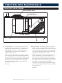
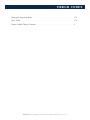
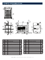
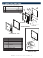
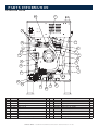
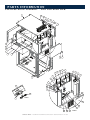
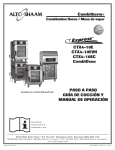
Combitherm®
Combination
Oven / Steamer
CT EXPRESS™
4•10ESi
4•10ESiVH
4•10CCi
CTX4-10E
CTX4-10EC
CTX4-10EVH
Shown with ExpressTouch control
and optional hand sprayer
• TECHNICAL
W164 N9221 Water Street • P.O. Box 450 • Menomonee Falls, Wisconsin 53052-0450 USA
PHONE: 262.251.3800 • 800.558.8744
printed in u.s.a.
usa / canada
FAX: 262.251.7067 • 800.329.8744 u . s . a .
www . alto - shaam . com
only
MN-36008 (Rev. 5) • 11/14
How to Use this Technical Service Manual
This manual has been compiled as a complete resource for a technician working on CT Express models. It includes
necessary product information and drawings, along with helpful troubleshooting procedures.
Introduction gives a quick overview of the CT Express to aid in model identification.
Sections A through E contain information applying to all CT Express models:
–CONTROL PANEL IDENTIFICATION includes information on using the controllers and operating instructions. It is
the same material supplied to the customer.
–PREVENTIVE MAINTENANCE includes procedures for cleaning with our without the CombiClean option. This
information is also supplied to the customer.
–SERVICE MODE AND ERROR CODES explains the special programming available to you as a technician to
view status, make adjustments and test functions on models equipped with Simple and Express Touch Controllers.
Information is also included on the use of displayed error codes to resolve problems and on the functions that can be
operated under fault conditions.
–TROUBLESHOOTING TREES are provided for the most common conditions you will be required to address.
–COMBITHERM PARTS has drawings and lists of available parts that are common to all electric models.
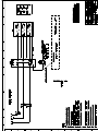
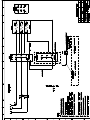
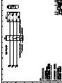
Sections F contains Wiring Diagrams that is specific to each model.
Navigation
Starting with the Main Table of Contents on the following page, you may click on any item that has a page number and
quickly jump to the information you need. Note that you may Return to the Main Table of Contents from the bottom of
any Section Contents page.
Printing
You may print the Current Page or any range of pages. Here’s a tip: Because printers vary in their capacity to handle large
drawings, make a test print of one of the Wiring Diagrams before printing the model’s section.
Combitherm CT Express Technical Service Manual • i
T A B L E OF C ON T EN TS
How to Use this Technical Service Manual...................................... i
Introduction.................................................................................. iii
Control Panel Identification............................................................ A-1
Preventive Maintenance................................................................. B-1
Service Mode and Error Codes....................................................... C-1
Troubleshooting Trees................................................................... D-1
Combitherm Parts......................................................................... E-1
Wire Diagrams.............................................................................. F-1
C o m b i t h e r m C T E x p r e s s T e c h n i c a l S e r v i c e M a n u a l • ii
INTRODUCTION
MODEL NUMBERS
This manual covers the following CT Express models:
4.10esi
4.10esiVH
4.10CCi
CTX4-10E
CTX4-10EC
CTX4-10EVH
FEATURES AND OPTIONS
Available on all models:
• Panel color choices
• Left-hand door
• Hand sprayer
• Single-point product temperature probe
• CombiClean® Tablet based cleaning system
• Stacking capabilities
Available only on ExpressTouch Control models:
• Smoker Mode
• Delta-T and Cook & Hold functionality
• HACCP data access
• Gold-n-Brown™ Feature
• Broiler element (not available on 1ph units)
• Catalytic Converter (CTX4-10EC only)
C o m b i t h e r m C T E x p r e s s T e c h n i c a l S e r v i c e M a n u a l • iii
E X P R ESSTO UCH OP E R A T I N G I N S T R U C T I O N S
ExpressTouch Control Operation
Start Up Procedures . . . . . . . . . . . . . . . . . . . . . . . . . . . . . . . . . . . . . . . . . . . . . . . .
Settings Screen. . . . . . . . . . . . . . . . . . . . . . . . . . . . . . . . . . . . . . . . . . . . . . . . . . . .
Upload/Download Screen. . . . . . . . . . . . . . . . . . . . . . . . . . . . . . . . . . . . . . . . . . . .
Cooking Mode Screen. . . . . . . . . . . . . . . . . . . . . . . . . . . . . . . . . . . . . . . . . . . . . . .
Cooking Mode Screen Identification. . . . . . . . . . . . . . . . . . . . . . . . . . . . . . . . . . . . .
Auxiliary Functions . . . . . . . . . . . . . . . . . . . . . . . . . . . . . . . . . . . . . . . . . . . . . . . . .
HACCP Access. . . . . . . . . . . . . . . . . . . . . . . . . . . . . . . . . . . . . . . . . . . . . . . . . . . .
Operation. . . . . . . . . . . . . . . . . . . . . . . . . . . . . . . . . . . . . . . . . . . . . . . . . . . . . . . .
A-2
A-3
A-4
A-5
A-6
A-7
A-8
A-9
Simple Control Operation
Screen Identification . . . . . . . . . . . . . . . . . . . . . . . . . . . . . . . . . . . . . . . . . . . . . . . . A-11
Operation. . . . . . . . . . . . . . . . . . . . . . . . . . . . . . . . . . . . . . . . . . . . . . . . . . . . . . . . A-12
Return to Main Table of Contents . . . . . . . . . . . . . . . . . . . . . . . . . . . . . . . . . . . . . . ii
C o n t r o l P a n e l I d e n t i f ic a t i o n • C o m b i t h e r m C T E x p r e s s T e c h n i c a l S e r v i c e M a n u a l • A – 1
E X P RE SSTO UCH O P E R A T I N G I N S T R U C T ION S
START-UP PROCEDURES
When the oven is powered on, the ExpressTouch screen
illuminates. “Loading” indicates that the software
is booting up. The screen will also indicate what level
of progress has been made as the software becomes
fully operational.
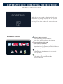
MAIN MENU SCREEN
leaning Mode (optional)
C
Four (4) cleaning levels are available:
rinse, light, normal, and heavy-duty cleaning.
ownload/Upload Files and
D
HACCP Access (optional)
Download all preprogrammed recipes (factory
default and user-programmed) and HACCP data to a
USB memory stick.
Settings
Change factory default settings. See next page for
more information.
ervice Mode (password protected)
S
This mode is only available to qualified
service technicians.
C o n t r o l P a n e l I d e n t i f ic a t i o n • C o m b i t h e r m C T E x p r e s s T e c h n i c a l S e r v i c e M a n u a l • A – 2
E X P R ESSTO UCH OP E R A T I N G I N S T R U C T I O N S
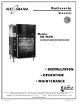
SETTINGS SCREEN
°F
7
Fahrenheit or Celsius Function - Choose
°F
temperature format.
°C
170
Note: After choosing your format, return
°C to10
the Main Menu screen and then Press Oven
Power switch off.
S
°F
°C7
10
°C
10
T
100%
S
M
T
W
T
F
S
1
2
3
4
5
6
7
8
9 12 10
11 12 13 14 15 16 17
18 19 20 21 22
9 23 24
25 26 27 28 29 30 31
6
S
100%
T
°C
T
Default Memo - Revert time/temperature
setting to factory defaults when switching
modes or keep the last user setting.
M
T
W
T
F
3
T
F
S
S
M
T
W
T
F
3
S
1
2
3
4
5
6
7
8
9 12 10
11 12 13 14 15 16 17
18 19 20 21 22
9 23 24
25 26 27 28 29 30 31
Touchscreen Brightness - Adjust brightness
of display screen.
100%
T
3
6
S
100%
T
W
6
Multi-shelf Timer Number
of Shelves °F
7
°F
7
Choose the default number of items in°Fthe oven
7
°C
to be used by the multi-shelf
timer.
1
0
°C
10
100%
T
7
°F
7
M
1
2
3
4
5
6
7
8
9 12 10
11 12 13 14 15 16 17
18 19 20 21 22
9 23 24
25 26 27 28 29 30 31
T
Language Choice - English, Spanish,
°F Mandarin,
7
°C
10
French, German, Korean and Russian are
°C
10
available.
°F
Sound/Alarm Settings - Change alarm sounds
and volume.
100%
M
S
T
T
W
T
F
Lock/Unlock Recipes - Password protect
preprogrammed recipes.
S
3
6
S
100%
T
M
T
W
T
F
S
1
2
3
4
5
6
7
8
9 12 10
11 12 13 14 15 16 17
18 19 20 21 22
9 23 24
25 26 27 28 29 30 31
6
3
Set/Change Date & Time - Set or change oven
time and date settings.
Calibrate Product Probe (optional)
T
W
T
F
S
1
2
3
S 4 M 5 T 6 W 7 T 8 F 9 12
S 10
11 12 13 14 1 15 2 16 3 17
231024
9 9 12
4 18 5 19 6 20 7 21 8 22
1125122613271428152916301731
10
M
1
2
3
4
5
6
7
8
9 12 10
11 12 13 14 15 16 17
18 19 20 21 22
9 23 24
25 26 27 28 29 30 31
100%
18 19 20 21 22
9 23 24
6
25 26 27 28 29 30 31
6
3
3
Software update - Upload new control software
to the oven using a USB drive.
S
100%
T
M
T
W
T
F
S
1
2
3
4
5
6
7
8
9 12 10
11 12 13 14 15 16 17
18 19 20 21 22
9 23 24
25 26 27 28 29 30 31
3
6
S
1
2
3
4
5
6
7
8
9 12 10
11 12 13 14 15 16 17
18 19 20 21 22
9 23 24
25 26 27 28 29 30 31
6
3
Return to Previous Screen - Return to previous
screen when finished adjusting settings.
Control Panel IdentIfICatIon • Combitherm Ct express teChniCal serviCe manual • a–3
E X P RE SSTO UCH O P E R A T I N G I N S T R U C T ION S
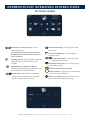
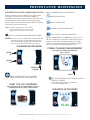
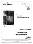
UPLOAD/DOWNLOAD SCREEN
Download Recipes
Copy all recipes from USB memory stick
to oven. This will replace and overwrite
existing recipes.
HACCP
DOWNLOAD
RECIPES
UPLOAD
RECIPES
GO TO
PREVIOUS
SCREEN
DOWNLOAD
HACCP INFO
ADD ALL
RECIPES
Upload Recipes
Copy all recipes from oven control to USB
memory stick.
Add All Recipes
Copy all recipes from USB memory stick to the
oven control. This will add the recipes to the
beginning of the existing recipe list.
HACCP
HACCP Data (optional)
Download data to a USB drive for review in a
.txt file format.
Control Panel IdentIfICatIon • Combitherm Ct express teChniCal serviCe manual • a–4
E X P R ESSTO UCH OP E R A T I N G I N S T R U C T I O N S
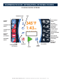
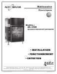
COOKING MODE SCREEN
TEMPERATURE
STEAM
MODE
TIME
MULTI-SHELF
TIMER
345°F
1:43 45
225°F
COMBINATION
MODE
CONVECTION
MODE
BROILER
MODE
(OPTIONAL)
DELAYED
START TIMER
CLEANING
REDUCED
POWER MODE
ADD RECIPE
GOLD-N-BROWN
MODE
FIND RECIPE
SMOKER MODE
(OPTIONAL)
RETHERM
MODE
CORE
TEMPERATURE
(OPTIONAL)
PREHEAT
FAN SPEED
START
COOL
DOWN
C o n t r o l P a n e l I d e n t i f ic a t i o n • C o m b i t h e r m C T E x p r e s s T e c h n i c a l S e r v i c e M a n u a l • A – 5
GO TO
PREVIOUS
SCREEN
E X P RE SSTO UCH O P E R A T I N G I N S T R U C T ION S
COOKING MODE SCREEN IDENTIFICATION
MAIN MENU ICONS
Power ON key
Activates power to the oven and automatically fills the
steam generator equipped models with water that will
heat to a stand-by mode temperature of 188°F (77°C).
Temperature
Used to set the required cooking temperature, to recall
the set cooking temperature, or to check the actual
oven temperature.
Time
Used to set the required cooking time or recall the set
cooking time.
Power OFF key
Press once to initiate power shut down sequence to the
Core Temperature (optional)
oven. Note: Oven will not shut down during a cooking
Used345°F
to set the required internal product temperature,
cycle. You may need to press harder due to the material
to recall the internal product temperature set by the
thickness. Firmly press and hold the OFF key for 10
1:43or45to display the current internal temperature of
operator,
seconds to power down the oven ONLY IF the control has
the
product.
locked and is unresponsive.
345°F 225°F
6
5
6
4
3
5
1:43 45 Preheat Mode
Steam Mode
5
225°FPreheats the oven cavity to a temperature set by user.
The oven will operate in the steam mode at a temperature
range of 85°F to 250°F 45
(30°C to 121°C).
4
Cool Down Mode
• Automatic steaming at 212°F (100°C)
3
Lowers temperature of the oven cavity at an accelerated
factory-set default.
pace to temperature set by user.
• Quick steaming between 213°F and 250°F (101°C
2
and 121°C).
• Low temperature steaming between 85°F and1 211°F
Delayed Start Time
6
345°F
(29°C and 99°C).
Quick and simple way to begin preheating your oven
45
1:43
5
while you’re away, and ready to go when you are.
Combination Mode
225°F
45
6
4
Selection key for cooking with a combination of steam
Start/Stop
and convection heat. Can be set between 212°F to 485°F
Initiates all cooking mode functions and programmed
5
3
(100°C and 252°C).
procedures stored in memory. Stops an activated cooking
6
45
4
2
mode or programmed procedure currently in progress.
5
Convection Mode
6
3
1
Selection key for convection
cooking without steam
at a
45
4
temperature range of 85°F to 485°F (29°C to 252°C).5 2
345°F
1:43
225°F
6
4
3
2
1
2
1
6
345°F
1:43
345°F
225°F
1:43
345°F
225°F
1:43
345°F
225°F
1:43 45
5
4
3
2
1
3
4
1
Broiler Mode (optional)
2
Quickly and efficiently toast or broil sandwiches, nachos,
3
soups, and desserts with the top shelf broiling element.
1
225°F
2
Retherm Mode
1
Food rethermalization or reheating mode will operate
with automatic steam injection at a temperature range of
245°F to 320°F (120°C to 160°C).
C o n t r o l P a n e l I d e n t i f ic a t i o n • C o m b i t h e r m C T E x p r e s s T e c h n i c a l S e r v i c e M a n u a l • A – 6
°F
3F45
F5
°F
°F
5°F
6
6
345°F
E X P R ESSTO UCH
OP
45 E R A T I N G I N S T R U C T I O N S
1:43
AUXILIARY FUNCTION ICONS 225°F
5
6
4
5
6
3
4
5
5
4
6
3
6
Find Recipe
Access a menu list 2of all stored cooking programs.
6
5
Reduced Power Mode
56
2
4
5
6 3
Used to reduce
kitchen4 power peaks and
energy consumption.
345°F345°F
1:43 45
345°F
45
1:43
Mode
F4545 Gold-N-Brown
225°F
This indicator will illuminate when
the browning
45
1:43
225°F
function
is
set
by
the
operator
in
a
timed
or
programmed
43
F 45 cooking cycle in any mode. Level225°F
1 provides least amount
°F
of browning, level 6 the most.
345°F
5°F Fan Speed
1:43sets45
This indicator will illuminate whenever the operator
a reduced fan speed to protect products affected by high225°F
velocity air movement.
1
5
3
2
4
63
4
45
6
52
2
1
3
3
34
5
2
23
4
41
6
2
1
3
5
1
2
1
12
3
1
2
4
1
63
52
Return to Previous Menu
1
41
Add Recipe
3
Used to create, change,
duplicate, and delete
programmed menus.
6
6
1
Multi-shelf Timer
5 for one or more shelves in the oven
Use separate
timers
56
compartment (only visible in time mode).
4
45
Steam Injection
(not shown on illustration)
3
34
Press to add
moisture in any cooking mode. Steam will
inject into the cavity
as long as the icon is touched.
2
23
6
Delta-T Core Temperature
(optional) - only visible
1
in certain1 2modes Cook5 by probe. Mode automatically
adjusts cooking temperature in proportion to the internal
4
1
temperature
of the product.
3
Smoking Mode (optional) - only visible in
2
convection mode or combination
mode. This indicator
will illuminate when the smoking function is set by the
1
operator in a timer, probe
or programmed cooking cycle.
2
1
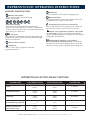
EXPRESSTOUCH FACTORY DEFAULT SETTINGS
COOKING MODE
OVEN TEMPERATURE
CORE TEMPERATURE
COOKING TIME
Steam
212°F
(100°C)
160°F
(70°C)
25 minutes
Combination Steam
350°F
(175°C)
160°F
(70°C)
70 minutes
Convection
350°F
(175°C)
160°F
(70°C)
30 minutes
Broiler/Finishing (optional)
_ _ _ _ °F
N/A
—— : ——
Retherm (available on
ExpressTouch only)
275°F
(135°C)
160°F
(70°C)
5 minutes
C o n t r o l P a n e l I d e n t i f ic a t i o n • C o m b i t h e r m C T E x p r e s s T e c h n i c a l S e r v i c e M a n u a l • A – 7
E X P RE SSTO UCH O P E R A T I N G I N S T R U C T ION S
HACCP ACCESS
The ExpressTouch Combitherm meets the requirements
of established HACCP criteria by providing automated
sampling, record keeping, set-point validation, recipe
used, dates and time. Data is captured when Core
Temperature Probe cooking method is chosen. This
information can be downloaded to a USB drive and then
copied to your computer. The file format is text (.txt).
NOTE: You can access this information from the
Upload/Download Screen. See illustrations on page
6 for navigation.
CAUTION: The CombiOven USB port is not
recommended for use with personal
hand held devices.
1. T
o download the data collected, remove the cap of a
USB port located on the side of the oven and insert the
USB flash drive. If the flash drive is not recognized
by the Combitherm, a question mark will appear on
screen. Try again with another flash drive device or
call Alto-Shaam Service.
2.
PRESS TO DOWNLOAD INFORMATION.
3.
AIT FOR THE ICON TO CHANGE FROM
W
LOADING TO COMPLETE.
4.
PRESS TO CONFIRM TRANSFER.
5. R
emove the USB flash drive and replace the cap on the
USB port.
The download process will automatically create a folder
on the USB flash drive titled “haccp”. Each text file
contains cooking program specifics. See illustration below.
C o n t r o l P a n e l I d e n t i f ic a t i o n • C o m b i t h e r m C T E x p r e s s T e c h n i c a l S e r v i c e M a n u a l • A – 8
E X P R ESSTO UCH OP E R A T I N G I N S T R U C T I O N S
345
345°F
1:43
345°F
• Choose a Mode.
345°F
45
1:43225
345°F
345°F
45
1:43
• Press the Power ON key.
or
• Press the Oven Temperature area to the right45of
1:43225°F
1:43
345°F
45 thermometer icon, set oven temperature on the
1:43the
225°F
keypad, and press Enter.
• Choose a Mode.
225°F
225°F 345°F
45
1:43225°F
• Press the Probe Temperature area to the right of
• Choose Preheat.
45
1:43225°F
the probe icon, set probe temperature on the
keypad, and press Enter.
225°F
• Type temperature on keypad and press Enter.
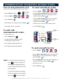
Turn on and preheat the oven
To cook manually by probe
6
Alto-Shaam recommends preheating the Combitherm before cooking.
®
6
6
Green light will
appear while oven
is booting up.
45
Steam
Combi
4
Convection Retherm
Steam
5
3
6
5
Convection Retherm
Combi
5
4
6
5
4
3
5
4
3
2
4
3
2
1
3
2
1
2
1
• Load food into oven and insert probe into food.
2
• Oven beeps when it is preheated.
To
cook with
345°F
preprogrammed recipes
1:43
225°F
• Press the Recipes key.
45
• Load food into oven.
• Press the Start key.
6
1
Oven
Temperature
area
5
4
3
• Locate food item program by scrolling
through pages using arrow keys.
2
HOLD
FOR FIVE SECONDS. THE
RED LIGHT WILL APPEAR INDICATING
THAT THE OVEN WILL BEGIN THE SHUT
5
4
3
Probe
Temperature
2
area
1
1
Start key
345°
345°F
1:43
• Choose a Mode.
345°F
45
1:43225°
45of the
• Press the Oven Temperature area 1:43
to the right
225°F
thermometer icon, set oven temperature on keypad,
225°F
and press Enter.
To cook manually by time
Steam
NOTE: TO SHUT THE OVEN OFF, PRESS AND
6
345°F
1:43 45
225°F
• Press preprogrammed food item icon.
• Oven begins operating automatically.
1
Combi
Convection Retherm
• Press the Cook Time area to the right of the timer, set
cook time on keypad, and press Enter.
• Load food into oven.
• Press the Start key.
DOWN PROCESS.
TO FORCE SHUT DOWN IN THE RARE
EVENT THE CONTROL LOCKS UP, PRESS
AND HOLD
FOR TEN SECONDS.
Control Panel IdentIfICatIon • Combitherm Ct express teChniCal serviCe manual • a–9
E X P RE SSTO UCH O P E R A T I N G I N S T R U C T ION S
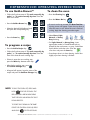
To use Gold-n-Brown™
• Follow the first three steps of “To cook manually by
probe” or “To cook manually by time” from the
front of this sheet.
345°F
1:43 45
• Press the Gold-n-Brown key.
225°F
345°F
1:43 45
225°F
• Select the desired Gold-n-Brown level
and press the corresponding key.
1
2
6
3
4
6
5
4
3
5
2
4
5
63
• Press the Start key.
2
6
345°F
To program a recipe
1:43 45
• Press the Add a Recipe key.
225°F
• Follow the first three steps of “To cook manually by
5
4
3
probe” or “To cook manually by time” from the
2
front of this sheet for each cooking step.
• If there is more than one cooking step,
press the Write key between each step.
1
1
To clean the oven
6
• Press the Cleaning key.
5
345°F
1:43 45
• Press the Water On key.
225°F
4
3
• If oven is too hot to proceed, the Oven Too Hot
2
warning screen will appear. Open the oven door to
allow the oven to cool. When the oven is finished
1
cooling, begin the cleaning procedure again.
• Select Rinse, Light,
Normal, or Heavy
Duty cleaning.
345°F
• For Light, Normal, or Heavy Duty, insert
1:43 45
appropriate number of CombiClean® tabs as
225°F
directed by the touchscreen, or spray CombiClean
Rinse
Light Normal Heavy Duty
liquid cleaner inside the oven. Close the
oven door and press the Start key.
• Oven beeps when it is done cleaning. Leave door
slightly ajar when cleaning is finished.
1
• After the last cooking step, press
the Confirm Changes key.
• A keypad will appear. Input the name of the
recipe and press the Confirm Changes key.
NOTE: TO SHUT THE OVEN OFF, PRESS AND
HOLD
FOR FIVE SECONDS. THE
RED LIGHT WILL APPEAR INDICATING
THAT THE OVEN WILL BEGIN THE SHUT
DOWN PROCESS.
TO FORCE SHUT DOWN IN THE RARE
EVENT THE CONTROL LOCKS UP, PRESS
AND HOLD
FOR TEN SECONDS.
C o n t r o l P a n e l I d e n t I f I C a t I o n • C o m b i t h e r m C t e x p r e s s t e C h n i C a l s e r v i C e m a n u a l • a – 10
S IMP LE CO NTR O L O P E R A T I N G I N S T R U C T ION S
CONTROL PANEL IDENTIFICATION
Set Oven
Temperature
Oven Temperature
display area
Steam Key
OVEN COOL DOWN
Combination Key
UP/INCREASE
Convection Key
DOWN/DECREASE
Cleaning Key
START/STOP
Set Cook
Time
Cook Time
display area
The Steam mode provides the operator with the ability
to steam, poach, or blanch. This mode will automatically
steam at the boiling point of water; quick-steam above the
boiling point for faster cooking results; or low temperature
steam, below the boiling point, for more delicate products
such as pâté, mousse, seafood, or custard.
The Combination mode will prove to be the most
versatile and widely used mode the Combitherm oven
has to offer. It will produce the best possible results on
the widest variety of products — all within the shortest
period of time. The unique control function of this mode
enables the operator to roast or bake with a combination
of steam and convection heat. In addition to shorter
cooking times, this combination of steam and heat offers
less product shrinkage and more moisture retention than
obtained in a standard convection oven.
The Convection mode operates with hot circulated air
within a temperature range of 85° to 485°F (29 to 252°C).
For many applications, better results may be
achieved with the Combination mode; therefore, the
operator may want to consider using the Convection
mode on a more limited basis.
Cook by Probe
setting
Oven Cool Down Process:
•Cooking process must be inactive
•Press "Cool Down" button until LED lights (LED
remains ON while in Cool Down mode)
•Press "Decrease Value" or "Increase Value" to adjust
cool down temperature
•Cook temperature display area is used to display
cool down temperature
•Display will show last valid cool down temperature
•Cool down temperature range is 85° - 575°F
(30° - 300°C)
•Press "Start/Stop" until LED lights to accept cool
down temperature and initiate cool down process
•Door must be open to start cool down process;
Cook time display area will display "door" if door
is not open
•Cook temperature display area will display set cool
down temperature
•Cook time display area will display current cool
down temperature
Fahrenheit or Celsius Function choose temperature format:
•Unit is not in a cooking or cleaning process
•Press "Set Cooking Temperature", "Decrease Value"
and "Increase Value" buttons simultaneously for
1 second
•Cooking temperature display area will display last
value "C" or "F"; Display will alternate between "C"
and "F" every 2 seconds
•Press "Start/Stop" key when the display is showing
the desired value ("C" or "F")
C o n t r o l P a n e l • C o m b i t h e r m C T E x p r e s s T e c h n i c a l S e r v i c e M a n u a l • A – 11
SIMP LE CO NTR O L O P E R A T I N G I N S T R U C T ION S
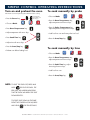
Turn on and preheat the oven
To cook manually by probe
Alto-Shaam recommends preheating the Combitherm before cooking.
®
• Press the Power key.
• Choose a Mode.
or
Steam
Combi
Green light will
appear while oven
is booting up.
• Choose a Mode.
Steam
Combi
Convection
• Press the Oven Temperature key;
adjust temperature with arrow keys.
Convection
• Press Oven Temperature key.
• Press the Probe Temperature key;
adjust temperature using the arrow keys.
• Adjust temperature with arrow keys.
• Load food into oven and insert probe into food.
• Press Cook Time key.
• Press the Start/Stop key.
• Adjust time with arrow keys.
• Press the Start/Stop key.
• Preheat oven before loading food.
To cook manually by time
• Choose a Mode.
Steam
Combi
• Press the Oven Temperature key;
adjust temperature with arrow keys.
• Press the Cook Time key; adjust
time using the arrow keys.
• Load food into oven.
• Press the Start/Stop key.
NOTE: TO SHUT THE OVEN OFF, PRESS AND
HOLD
FOR FIVE SECONDS. THE
RED LIGHT WILL APPEAR INDICATING
THAT THE OVEN WILL BEGIN THE SHUT
DOWN PROCESS.
TO FORCE SHUT DOWN IN THE RARE
EVENT THE CONTROL LOCKS UP, PRESS
AND HOLD
FOR TEN SECONDS.
C o n t r o l P a n e l • C o m b i t h e r m C t e x p r e s s t e C h n i C a l s e r v i C e m a n u a l • a – 12
Convection
PREVENTATIVE MAINTENANCE
Cleaning Agents . . . . . . . . . . . . . . . . . . . . . . . . . . . . . . . . . . . . . . . . . . . . . . . . . . . B-2
Preventative Maintnance . . . . . . . . . . . . . . . . . . . . . . . . . . . . . . . . . . . . . . . . . . . . . B-3
Protecting Stainless Steel. . . . . . . . . . . . . . . . . . . . . . . . . . . . . . . . . . . . . . . . . . . . . B-4
Cleaning Schedule. . . . . . . . . . . . . . . . . . . . . . . . . . . . . . . . . . . . . . . . . . . . . . . . . . B-5
Ventless Hood Filters. . . . . . . . . . . . . . . . . . . . . . . . . . . . . . . . . . . . . . . . . . . . . . . . B-6
Express Touch with CombiClean . . . . . . . . . . . . . . . . . . . . . . . . . . . . . . . . . . . . . . . B-7
Simple Control with CombiClean. . . . . . . . . . . . . . . . . . . . . . . . . . . . . . . . . . . . . . . B-8
Cleaning without CombiClean Program . . . . . . . . . . . . . . . . . . . . . . . . . . . . . . . . . . B-9
Return to Main Table of Contents . . . . . . . . . . . . . . . . . . . . . . . . . . . . . . . . . . . . . . ii
Preventative Maintenance • Combitherm CT Express Technical Service Manual • B–1
PREVENTATIVE MAINTENANCE
C ombi C lean CLEANING AGENTS
CombiClean tablets are to be used only with the factory installed automatic cleaning option.
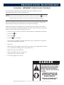
DANGER
RUBBER GLOVES MUST BE WORN WHEN USING
COMBICLEAN TABLETS OR SPRAY OVEN CLEANER.
DANGER
PROTECTIVE EYE WEAR MUST BE WORN
WHEN USING SPRAY OVEN CLEANER.
NOTE: Use authorized Combitherm cleaner only.
FIRST AID:
Unauthorized cleaning agents may discolor or harm
interior surfaces of the oven. Read and understand
label and material safety data sheet before using the
oven cleaner.
Skin: Flush with water. Remove contaminated clothing
and do not re-wear until washed. If irritation persists see
a physician.
CAUTION: C
auses eye, skin, and respiratory tract
irritation. keep out of reach of children.
PRECAUTIONS:
- Do not take internally.
- Avoid contact with eyes and skin.
- Use rubber gloves when using this product.
- Wash hands thoroughly after handling.
- Avoid mixing with strong, concentrated acids.
Eyes: Flush with water for 15 minutes. See a
physician immediately.
Inhalation: If difficulty in breathing occurs, leave area
immediately and do not return until dust is settled. If
irritation persists, see a physician.
Ingestion: Drink large quantities of milk or water. DO
NOT INDUCE VOMITING. See a physician immediately.
PROTECTIVE PACKAGING OF TABLETS WILL
BEGIN TO DISSOLVE ONTO SKIN IF HANDLED
WITH DAMP OR WET HANDS.
Preventative Maintenance • Combitherm CT Express Technical Service Manual • B–2
PREVENTATIVE MAINTENANCE
PREVENTATIVE MAINTENANCE
In addition to the routine cleaning and maintenance
procedures, there are several additional steps to be
taken for both sanitation and to keep the oven running
efficiently. These additional safeguards will help prevent
down time and costly repairs.
DO NOT DISPOSE OF GREASE, FAT, WOOD CHIPS
OR SOLID WASTE DOWN THE OVEN DRAIN.
Fats and solids will eventually coagulate in the drain
system, causing blockage. Consequently, water
will back-up into the condenser and interior oven
compartment, resulting in an oven that is inoperable.
MAKE CERTAIN THE DRAIN SCREEN IS ALWAYS
IN PLACE. REMOVE ANY SOLID WASTE MATERIAL
FROM THE DRAIN SCREEN BEFORE IT ENTERS THE
DRAIN SYSTEM.
The routine removal of solids from the drain screen will
help prevent blockage.
USE THE AUTHORIZED COMBITHERM OVEN
CLEANER ONLY.
The use of unauthorized cleaning agents may discolor or
harm the interior surfaces of the oven.
TO PROLONG THE LIFE OF THE DOOR GASKET,
CLEAN THIS ITEM DAILY.
The acids and related compounds found in fat,
particularly chicken fat, will weaken the composition of
the gasket unless cleaned on a daily basis. Wipe with a
hot, soapy cloth.
TO ADDITIONALLY PROTECT GASKET LIFE,
ALLOW OVEN DOOR TO REMAIN SLIGHTLY OPEN
AT THE END OF THE PRODUCTION DAY.
An open door will relieve the pressure on the door gasket.
ROUTINELY CLEAN DOOR HINGES.
Open oven door to relieve tension. Clean all parts of
the hinge.
PROBE CABLE PLACEMENT.
The probe cable should not be placed near the broiler
element at the top of the oven.
When smoking is completed, remove smoker box
from oven. Dispose of wood chips in a fireproof
waste receptacle.
DANGER
AT NO TIME SHOULD THE INTERIOR
OR EXTERIOR BE STEAM CLEANED,
HOSED DOWN, OR FLOODED WITH
WATER OR LIQUID SOLUTION OF
ANY KIND. DO NOT USE WATER JET
TO CLEAN.
SEVERE DAMAGE OR
ELECTRICAL HAZARD
COULD RESULT.
WARRANTY BECOMES VOID IF
APPLIANCE IS FLOODED
Preventative Maintenance • Combitherm CT Express Technical Service Manual • B–3
PREVENTATIVE MAINTENANCE
CLEANING AND PREVENTATIVE MAINTENANCE
PROTECTING STAINLESS STEEL SURFACES
CLEANING AGENTS
It is important to guard against corrosion
in the care of stainless steel
surfaces. Harsh, corrosive,
or inappropriate chemicals
can completely destroy the
protective surface layer
of stainless steel. Abrasive
pads, steel wool, or metal implements will abrade
surfaces causing damage to this protective coating
and will eventually result in areas of corrosion.
Even water, particularly hard water that contains
high to moderate concentrations of chloride, will
cause oxidation and pitting that result in rust
and corrosion. In addition, many acidic foods
spilled and left to remain on metal surfaces are
contributing factors that will corrode surfaces.
Use non-abrasive cleaning products designed for
use on stainless steel surfaces. Cleaning agents
must be chloride-free compounds and must not
contain quaternary salts. Never use hydrochloric
acid (muriatic acid) on stainless steel surfaces.
Always use the proper cleaning agent at the
manufacturer's recommended strength.
Contact your local cleaning supplier for
product recommendations.
Proper cleaning agents, materials, and
methods are vital to maintaining the appearance
and life of this appliance. Spilled foods should be
removed and the area wiped as soon as possible
but at the very least, a minimum of once a day.
Always thoroughly rinse surfaces after using a
cleaning agent and wipe standing water as quickly
as possible after rinsing.
CLEANING MATERIALS
The cleaning function can usually be accomplished
with the proper cleaning agent and a soft, clean
cloth. When more aggressive methods must be
employed, use a non-abrasive scouring pad on
difficult areas and make certain to scrub with the
visible grain of surface metal to avoid surface
scratches. Never use wire brushes, metal scouring
pads, or scrapers to remove food residue.
CAUTION
RS
NO
RA PE
SC
S
ST
E EL P A
DS
NO
BRU
S
NO
IR E
HE
W
TO PROTECT STAINLESS STEEL
SURFACES, COMPLETELY AVOID
THE USE OF ABRASIVE CLEANING
COMPOUNDS, CHLORIDE BASED
CLEANERS, OR CLEANERS
CONTAINING QUATERNARY SALTS.
NEVER USE HYDROCHLORIC ACID
(MURIATIC ACID) ON STAINLESS
STEEL. NEVER USE WIRE
BRUSHES, METAL SCOURING
PADS OR SCRAPERS.
Preventative Maintenance • Combitherm CT Express Technical Service Manual • B–4
PREVENTATIVE MAINTENANCE
CLEANING SCHEDULE
DAILY GASKET CLEANING
It is important to prolong the life of the oven gasket
by cleaning on a daily basis. Routine cleaning will
help protect the gasket from deterioration caused by
acidic foods.
1. Allow the oven to cool, then wipe the gasket
and crevices with clean cloth soaked in warm
detergent solution.
2. Wipe the gasket and crevices with a cloth and clean
rinse water.
Do not attempt to remove gasket or place
in the dishwasher.
DAILY OVEN CLEANING
To be performed at the end of the production day or
between production shifts.
CLEANING CYCLE NEEDED AFTER SMOKING
To prevent the transfer of smoke residue to non-smoked
products, a cleaning cycle is required before cooking
non-smoked items.
MONTHLY CLEANING
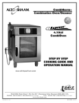
1. Spray Head
2. Water Intake Filters
PROBE USAGE AND CLEANING
After each use of the CORE TEMP mode, wipe the probe
tip with a clean paper towel to remove food debris. Follow
by wiping the probe with a disposable alcohol pad. Return
the probe to the proper door bracket position. The probe
cable should not be placed near the broiler element at the
top of the oven.
Probe Cleaning Procedures
1. Remove all food debris from probe between loads and
at the end of each production shift. Wipe the entire
probe, probe cable assembly, and probe holding bracket
with a clean cloth and warm detergent solution.
2. Remove detergent by wiping the probe, cable, and
bracket with a cloth and clean rinse water.
3. Wipe probe and probe bracket with disposable alcohol
pad or sanitizing solution recommended for food
contact surfaces.
4. Allow probe and cable to air dry in the probe
holding bracket. The probe cable should not be placed
near the broiler element at the top of the oven.
5. Wipe the probe with a disposable alcohol pad prior to
inserting into a new food product.
3. Drain Pipe
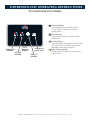
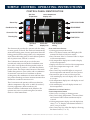
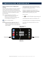
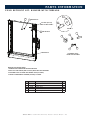
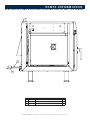
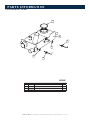
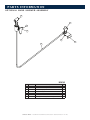
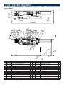
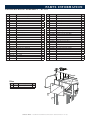
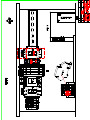
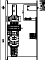
1
TETHER BRACKET
REQUIRED FOR
380-415V, CASTER STAND,
OR STACKING KITS
HI-LIMIT
RESET
ELECTRICAL CONNECTION
(CORD OR HARDWIRE)
WATER INLET
3/4" G
2
HAND SPRAYER VALVE
REQUIRES SEPERATE
WATER CONNECTION
3
1-1/2" DRAIN
TANK CLEAN-OUT
DANGER
AT NO TIME SHOULD THE INTERIOR
OR EXTERIOR BE STEAM CLEANED,
HOSED DOWN, OR FLOODED WITH
WATER OR LIQUID SOLUTION OF
ANY KIND. DO NOT USE WATER JET
TO CLEAN.
SEVERE DAMAGE OR
ELECTRICAL HAZARD
COULD RESULT.
TOLERANCE: UNLESS SPECIFIED:
WARRANTY BECOMES VOID IF
APPLIANCE IS FLOODED
Preventative Maintenance • Combitherm CT Express Technical Service Manual • B–5
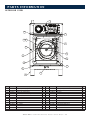
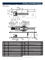
PREVENTATIVE MAINTENANCE
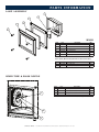
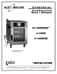
VENTLESS HOOD MODEL
TOP EXHAUST VENT
FILTER TRACK
FILTER SWITCH
1
2
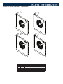
1. Charcoal Filter: The charcoal filter should be
inspected for contaminant's on a regular basis.
Replacement must be made at a minimum of
three month intervals — more often if heavy
contaminant's are visible or if the filter no
longer controls odors.
To remove the charcoal filter, pull and slide out.
When replacing the filter, ensure that the filter
clip is in place at rear of the filter. Make certain
the air flow arrow(s) point toward the hood fan
(back of unit), and that the filter is replaced
using the filter track in the metal back plate
provided with the hood.
FI-24114
2. Grease Filter: Cleaning frequency should be
based on oven usage with a maximum of two
weeks between cleaning if the oven is used for
non-grease laden products or steam applications
only. Grease laden products require cleaning
frequency of at least once a week.
Remove the grease filter by pulling it straight
out of the housing. Place the filter in the
dishwasher or wash separately by placing in
hot, soapy water until all grease and particles
have been removed. Rinse thoroughly. Allow
the filter to air dry before reinstalling.
To replace the grease filter, the metal handles
on the filter casing should be facing toward the
front of the unit.
FI-24113
Preventative Maintenance • Combitherm CT Express Technical Service Manual • B–6
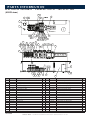
PREVENTATIVE MAINTENANCE
EXPRESSTOUCH WITH COMBICLEAN OPTION
Four (4) cleaning levels are offered: rinse, light, normal,
and heavy-duty cleaning. CombiClean® tablets or
Combitherm liquid spray cleaner may be used. Side racks
and shelves may remain inside oven during cleaning.
Remove solid wastes from the bottom of the oven and the
drain screen to prevent blockage.
Note: If a power outage were to occur during
any of the cleaning cycles, the oven will
begin a six (6) minute forced-rinse cycle.
SELECT CLEANING MODE FROM ANY SCREEN.
NOTE: If oven is too hot to safely clean, an oven with red
interior will appear on the screen and the cool
down function is automatically activated. Allow
oven to cool to 200°F (93°C) before cleaning.
CLEANING MODE MENU
SELECT DESIRED LEVEL OF CLEANING.
RINSE (20 MINUTES)
LIGHT (30 MINUTES)
NORMAL (1 HOUR 21 MINUTES)
HEAVY-DUTY (2 HOURS 6 MINUTES)
INSERT APPROPRIATE NUMBER OF CombiClean 1 oZ
oR 0.5 oZ TABLETS as directed by touchscreen or spray
interior of oven with combitherm liquid spray cleaner.
User may add one additional tablet in either normal or
heavy duty modes for particularly dirty ovens.
COMBI CLEANER REQUIREMENT
The number of required CombiClean
tabs is shown.
WATER
ON
4
WATER
OFF
PREVIOUS
SCREEN
PRESS WATER ON ICON TO CONFIRM
THAT WATER SUPPLY IS TURNED ON.
OVEN TOO HOT WARNING
Must allow oven to cool down before inserting
CombiClean tabs or spraying with cleaner
START
TOUCH THE GREEN START ARROW ICON TO
BEGIN CLEANING.
Oven beeps when cleaning is finished.
Leave door slightly ajar.
CLEANING IN PROCESS
Preventative Maintenance • Combitherm Ct express teChniCal serviCe manual • b–7
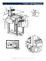
PREVENTATIVE MAINTENANCE
SIMPLE CONTROL WITH COMBICLEAN
OPTION
One (1) heavy-duty cleaning cycle (2 hours 5 minutes) is
offered. CombiClean® tablets or Combitherm liquid
spray cleaner may be used. Side racks and shelves may
remain inside oven during cleaning. Remove solid wastes
from the bottom of the oven and the drain screen to
prevent blockage.
Note: I f a power outage were to occur during
any portion of the cleaning cycle, the oven will
begin a six (6) minute forced-rinse cycle.
Cook temperature display area will display “RIN”.
Cook time display area will display “-.--”
SELECT CLEANING MODE.
Cooking temperature display area will display "CLn".
Cooking time display area will display "6" - referring to
the number of cleaning tablets to insert.
Lift interior oven drain screen and insert six (6)
CombiClean TABLETS or spray interior of oven with
Combitherm liquid spray cleaner. User may add one
additional tablet for particularly dirty ovens.
Close oven door.
Press
key until the LED lights to begin cleaning cycle.
Cooking temperature display area will display "CLn".
Cooking time display area will display time remaining.
NOTE: If oven is too hot to safely clean, "door" will
Oven beeps when cleaning is finished. Leave door
appear on the screen and the cool down
slightly ajar.
function is automatically activated. Open the
oven door to allow oven to cool to 200°F (93°C)
before cleaning.
Oven Temperature
display area
Cleaning Key
START/STOP
Cook Time
display area
Preventative Maintenance • Combitherm CT Express Technical Service Manual • B–8
PREVENTATIVE MAINTENANCE
CLEANING - WITHOUT COMBICLEAN PROGRAM
The CT Express Combitherm can be ordered without the CombiClean® option.
Combitherm liquid spray cleaner should be used.
NOTE: If oven is too hot to safely clean, touch the cool down function key
to activate.
Open the oven door to allow oven to cool to 200°F (93°C) before cleaning.
ide racks and shelves may remain inside oven during cleaning. Remove solid wastes
S
from the bottom of the oven and the drain screen to prevent blockage.
earing safety glasses and rubber gloves, generously spray the interior oven surfaces
W
with an even coating of Combitherm Liquid Oven Cleaner. Spray all built in components,
shelves, and side racks. Spray both sides of the oven.
• Securely close the oven door and let the solution stand for a minimum of 10 minutes.
• Press Power
• Press Steam
• Set Time
on.
.
for ten minutes.
• Oven beeps for 3 minutes at the end of the steam cycle or until the door is opened or
until a cook mode button is pressed.
• Open door.
• Make certain to thoroughly rinse all surfaces to remove any cleaning solution residue.
Use a non-abrasive cleaning pad for any problem areas.
• Replace the side racks and shelves.
• Wipe door gasket with a hot, soapy cloth.
Wipe again with a clean rinse cloth.
• Leave door slightly ajar to air dry.
DANGER
AT NO TIME SHOULD THE INTERIOR
OR EXTERIOR BE STEAM CLEANED,
HOSED DOWN, OR FLOODED WITH
WATER OR LIQUID SOLUTION OF
ANY KIND. DO NOT USE WATER JET
TO CLEAN.
SEVERE DAMAGE OR
ELECTRICAL HAZARD
COULD RESULT.
WARRANTY BECOMES VOID IF
APPLIANCE IS FLOODED
Preventative Maintenance • Combitherm CT Express Technical Service Manual • B–9
ERROR CODES
Emergency Operation Mode . . . . . . . . . . . . . . . . . . . . . . . . . . . . . . . . . . . . . . . . . . C-2
Error Codes . . . . . . . . . . . . . . . . . . . . . . . . . . . . . . . . . . . . . . . . . . . . . . . . . . . . . . C-3
Return to Main Table of Contents . . . . . . . . . . . . . . . . . . . . . . . . . . . . . . . . . . . . . . ii
Error Codes • Combitherm CT Express Technical Service Manual • C–1
ERROR CODES
EMERGENCY OPERATION MODE
If the oven malfunctions, an error code will appear in the
display. In the event of an error, the Combitherm may be
operated on a limited basis. Error conditions under which
continued operation is possible are indicated by “Yes”
in the chart on the next page. To operate the oven in the
event of an error code:
RESS THE START ICON TO ACKNOWLEDGE
P
THE ERROR.
The icons that begin to flash represent operational
modes that are still usable.
SELECT ONE OF THE AVAILABLE COOKING MODES.
SET THE OVEN CONTROLS AS IF OPERATING UNDER
NORMAL CIRCUMSTANCES.
Depending on the error code involved, oven function,
such as temperature range, may be limited.
PRESS THE START ICON TO BEGIN COOKING.
PRESS THE STOP ICON WHEN TIMER EXPIRES.
The Combitherm will return to normal operation when
the oven fault is corrected.
Error Codes • Combitherm CT Express Technical Service Manual • C–2
ERROR CODES
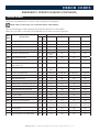
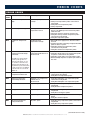
EMERGENCY OPERATION MODE (CONTINUED)
ERROR CODES
When the oven malfunctions, an error code will appear in the display.
PRESS THE START ICON TO ACKNOWLEDGE THE ERROR.
The icons that begin to flash represent operational modes that are still usable.
When the oven fault is corrected, the Combitherm will return to normal operation.
Error
Code
Model
Display Shows
Mode
ES
ESG
ESI
Steam
Combination
Convection
Retherm
E01
Low Water Boiler
Yes
No
No
No
To 365°F/185°C
No
E02
Control Temp High
Yes
Yes
No
No
No
No
E03
Fan Motor Error
Yes
Yes
No
No
No
No
E04
Fan Motor 2 Error
Yes
Yes
No
No
No
No
E11
Convection Temperature High
Yes
Yes
BOILER UNITS
ONLY
No
No
No
E13
Boiler Temperature High
Yes
No
No
No
Yes
No
E15
Condenser Temperature High
Yes
Yes
No
No
To 356°F/180°C
No
E20
B11 Core Temperature Probe Single Point
Fault - HACCP only
Yes
Yes
No
No
No
No
E21
N6 Cavity Probe Fault
Yes
Yes
BOILER UNITS
ONLY
No
No
No
E22
B10 Core Temp Probe Fault
Yes
Yes
BY TIME ONLY
BY TIME ONLY
BY TIME ONLY
BY TIME ONLY
E23
B4 Boiler Probe Fault
Yes
No
No
No
No
No
E24
B5 Bypass Probe Fault
Yes
Yes
No
No
Yes
No
E25
B3 Condenser Probe Fault
Yes
Yes
Yes
No
To 356°F/180°C
No
E26
N8 Boiler Safety Temperature Probe Fault
Yes
No
No
No
No
No
E27
Boiler Element Temperature High
Yes
No
No
No
Yes
No
E34
Steam Generator Drain Pump Fault
Yes
No
No
No
No
No
E36
Steam Temperature High
Yes
No
No
No
Yes
No
E51
No Water in Boiler
Yes
No
No
No
Yes
No
E53
Fan Motor High Temperature
Yes
Yes
No
No
No
No
E54
Fan Motor 2 High Temperature
Yes
Yes
No
No
No
No
E55
Vent Not Open
Yes
Yes
Yes
(NO BROWNING)
Yes
(NO BROWNING)
Yes
(NO BROWNING)
Yes
(NO BROWNING)
E57
No Rinse Water
Yes
Yes
Yes
Yes
Yes
Yes
E93
Communication Error FROM Display Board
Yes
Yes
No
No
No
No
E94
Communication Error TO Display Board
Yes
Yes
No
No
No
No
Error Codes • Combitherm CT Express Technical Service Manual • C–3
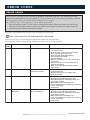
ERROR CODES
ERROR CODES
This section is provided for the assistance of qualified technicians only and is not intended for use by
untrained or unauthorized service personnel. If your Alto-Shaam ® unit is not operating properly, check the
following before calling your Authorized Alto-Shaam Service Agent:
☛ Check that unit is receiving power. Circuit breaker turned on?
Do not attempt to repair or service the oven beyond this point. Contact Alto-Shaam for the nearest
authorized service agent. Repairs made by any other service agents without prior authorization by
Alto-Shaam will void the warranty on the unit.
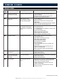
When the oven malfunctions, an error code will appear in the display.
PRESS THE START ICON TO ACKNOWLEDGE THE ERROR.
The icons that begin to flash represent operational modes that are still usable.
When the oven fault is corrected, the Combitherm will return to normal operation.
Error
Code
Error Call Out in Display
Description of Error
Possible Cause
E01
Low Water Boiler
Low water level in boiler
— Water supply is shut off.
— Low water pressure.
— Generator drain cap/hose missing or leaking.
— Generator drain pump is defective.
— Generator drain pump elbow leaking.
— Fill solenoid not energized.
— Fill solenoid faulty.
— Wiring or connection error at the solenoid or the
relay board.
— Water level probe connection/wiring error at
probe or relay board.
— Water level probe requires descaling and/or
replacement.
E02
Control Temperature High
Relay board surface
temperature too high
— Cooling fan(s) not being energized.
— Cooling fan(s) faulty.
— Wiring/connection error at cooling fan(s).
— Faulty relay board.
E03
Convection Fan Motor Error
Convection fan motor failure
— Motor VFD not energized.
— No input signal to VFD from relay board.
— Motor VFD faulty, not outputting to motor after
input signal received.
— Motor fan wheel blocked/obstructed.
— Connection/wiring error at VFD, motor, hall effect
sensor, relay board.
— Faulty motor.
E04
Lower Convection Fan
Motor Error
Lower convection fan motor
failure on 20•20 unit
— Motor VFD not energized.
— No input signal to VFD from relay board.
— Motor VFD faulty, not outputting to motor after
input signal received.
— Motor fan wheel blocked/obstructed.
— Connection/wiring error at VFD, motor, hall effect
sensor, relay board.
— Faulty motor.
Error Codes • Combitherm CT Express Technical Service Manual • C–4
(CONTINUED ON NEXT PAGE)
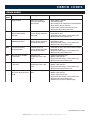
ERROR CODES
ERROR CODES
Error
Code
Error Call Out in Display
Description of Error
E11
Convection Temperature
High
Oven cavity temperature N6
too high
— Convection element contactor stuck closed/on.
— Faulty oven temperature probe connection at
relay board.
— Faulty N6 oven temperature probe.
— Faulty relay board.
E13
Boiler Temperature High
Steam generator
temperature too hot
— Immersion element is not submersed in water
due to scale build up on the water level probe/
inside the tank.
— Immersion element contactor stuck closed.
— Faulty B4 steam generator temperature probe
connection at relay board.
— Faulty B4 temperature probe.
E15
Condensor Temperature
High
Condensor water
temperature too high
— Untreated water supply line is disconnected or
shut off.
— Cooling solenoid is not being energized when B3
probe is above set point.
— Faulty B3 condensate temperature probe
connection at relay board.
— Faulty B3 condensate temperature probe.
E20
HACCP Only - B11 Core
Temperature Probe Single
Point Fault
Single point core
temperature probe defect or
disconnected
— Probe not installed inside oven.
— Faulty B11 Single Point Core Temperature probe
receptacle connection at relay board.
— Faulty B11 single point core temperature probe.
— Debris buildup on probe receptacle pins inside of
the oven.
Error E20 is not shown in display.
Instead a probe sign with “?” is
shown as popup window. In case
the customer cooks in time mode
during first step and during second
step switches to probe mode but has
no probe in place, the error E20 will
be shown in the error code list and
HACCP list.
Possible Cause
E21
N6 Oven Cavity
Temperature Probe Fault
N6 probe “open”
— Faulty N6 oven cavity temperature probe
connection at relay board.
— Faulty N6 oven temperature probe.
E22
B10 Core Temperature
Probe Multipoint Fault
Multipoint core temperature
probe defect or
disconnected
— Faulty B10 multipoint core temperature probe
connection at relay board.
— Faulty B10 multipoint core temperature probe.
E23
B4 Boiler Probe Fault
B4 probe “open”
— Faulty B4 boiler temperature probe connection at
relay board.
— Faulty B4 boiler temperature probe.
E24
B5 Bypass Probe Fault
B5 probe “open”
— Faulty B5 steam bypass probe connection at
relay board.
— Faulty B5 steam bypass probe.
E25
B3 Condensor Probe Fault
B3 probe “open”
— Faulty B3 condensor probe connection at relay
board.
— Faulty B3 condensor probe.
E26
N8 Immersion Element
Safety Probe Fault
N8 probe “open”
— Faulty N8 safety temperature probe connection at
relay board.
— Faulty N8 safety temperature probe.
(CONTINUED ON NEXT PAGE)
Error Codes • Combitherm CT Express Technical Service Manual • C–5
ERROR CODES
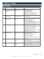
ERROR CODES
Error
Code
Error Call Out in Display
Description of Error
Possible Cause
E27
N8 Immersion Element
Temperature Too High
Immersion element too hot
E34
Steam Generator Drain
Pump Fault
Water level in steam
generator does not drop
during cleaning program
— Scale buildup inside the steam generator and/or
water level probe.
— Obstruction on inlet side of steam generator
drain pump.
— Boiler steam generator pump not being energized.
— Steam generator drain pump defective.
E36
Steam Temperature High
Oven cavity temperature is
too high when operating in
steam mode or combination
mode
— Water supply is not connected or shut off.
— Low water pressure.
— Y1 solenoid valve not energized on a call for steam.
— Y1 solenoid faulty.
— Flow restrictor obstructed.
— Water injection pipe obstructed.
— Steam bypass hose obstructed.
— B5 steam bypass probe dirty or faulty.
E51
No Water In Boiler
Steam generator fill error
— Water supply is disconnected or shut off.
— Low water pressure.
— Boiler drain cap leaking or missing.
— Boiler drain pump defective.
— Drain pump elbow leaking.
— Fill solenoid not energized.
— Fill solenoid faulty.
— Connection/wiring error at the solenoid or the
relay board.
— Water level probe connection/wiring error at
probe or the relay board.
— Water level probe requires descaling and/or
replacement.
E53
Fan Motor High
Temperature
Fan motor high limit
— Faulty motor high limit connection at relay board.
— Obstructed fan wheel.
— Faulty convection motor.
E54
Lower Fan Motor High
Temperature (20-20 unit
size only)
Fan motor high limit
— Faulty motor high limit connection at relay board.
— Obstructed fan wheel.
— Faulty convection motor.
E55
Vent Not Open
Browning valve does not
open
— Browning valve vent motor not being energized.
— Alignment issue between motor cam and vent
motor safety switch (micro switch).
— Faulty connection at vent motor, vent motor
switch or relay board.
— Fault vent valve safety switch (micro switch).
— Faulty vent motor.
— Scale buildup inside steam generator and/or on
water level probe.
— Immersion element contactor stuck closed.
— Faulty N8 safety temperature probe.
(CONTINUED ON NEXT PAGE)
Error Codes • Combitherm CT Express Technical Service Manual • C–6
ERROR CODES
ERROR CODES
Error
Code
Error Call Out in Display
Description of Error
Possible Cause
E57
No Rinse Water
During rinse no water
flow is detected through
solenoid valve
— Water supply is shut off.
— Low water pressure.
— Check wiring to all components mentioned below.
— Flow switch is dirty or defective.
— Double water solenoid valve defective (Y3.)
— Relay board, high voltage, defective.
E92
Communication Error,
RB Does Not Properly
Respond
Communication error
between display board and
relay board
— Faulty ribbon cable connections between boards.
— Faulty ribbon cable.
— Relay board, low voltage, connector defective.
— Display board connector defective.
E93
Communication Error,
FROM Display Board
Communication error
between display board and
low voltage relay board
— Faulty ribbon cable connections between boards.
— Faulty ribbon cable.
— Relay board, low voltage, connector defective.
— Display board connector defective.
E94
Communication Error,
TO Display Board
Communication error
between display board and
low voltage relay board
— Faulty ribbon cable connections between boards.
— Faulty ribbon cable.
— Relay board, low voltage, connector defective.
— Display board connector defective.
E98
RB is in Celsius and DB is
in Fahrenheit
Change the unit
configuration in the setup
menu
— Control programming issue.
— Ribbon cable defective.
— Relay board, low voltage, connector defective.
— Display board connector defective.
E99
RB is in Fahrenheit and DB
is in Celsius
Change the unit
configuration in the setup
menu
— Control programming issue.
— Ribbon cable defective.
— Relay board, low voltage, connector defective.
— Display board connector defective.
E100
DB version is not equal to
RB version. Error generated
by DB.
Software update may have
failed.
— Perform software update.
— Ribbon cable defective.
— Faulty compact flash card.
— Relay board, low voltage, connector defective.
— Display board connector defective.
— Software may need to be updated again.
(CONTINUED ON NEXT PAGE)
Error Codes • Combitherm CT Express Technical Service Manual • C–7
ERROR CODES
ERROR CODES
Error
Code
Error Call Out in Display
Description of Error
Possible Cause
E101
DB version is not equal to
RB version. Error generated
by RB.
Software update may have
failed.
— Perform software update.
— Ribbon cable defective.
— Faulty compact flash card.
— Relay board, low voltage, connector defective.
— Display board connector defective.
— Software may need to be updated again.
E102
Ventless Hood Fault —
Filters Not Present
Filter safety switches are
not properly activated.
— Grease and/or charcoal filter not installed.
— Faulty filter switch.
— Poor connection at safety switch or relay board.
E103
Ventless Hood Fault –
Pressure Failure
Ventless hood operation
failure.
— Hood power switch not turned to the on position.
— Hood power switch defective.
— Hood fan not operating.
— Filter(s) clogged/need replacement.
— Pressure switch tube plugged or disconnected.
— Faulty pressure switch or connection error/failure.
— Hood fan turning in the wrong direction.
E104
Ignition Failure
Attempt for ignition.
— Gas supply disconnected or turned off.
— Gas supply pressure too low/too high.
— Gas valve not being energized by ignition control.
— Ignition control not creating a spark.
— Faulty spark wire and/or igniter.
— Faulty flame sense wire or sensing wire connection.
— Faulty ignition control.
— Blocked or obstructed flue pipe(s).
E105
Low Water Pressure
Low or no water pressure to
oven.
— Water supply not connected or turned off.
— Water pressure too low.
— Solenoid valve not being energized.
— Solenoid valve not opening.
— Pressure switch faulty.
— Poor connection at pressure switch and/or relay
board.
E106
Cleaning Pump Fault
Cleaning pump is not
running.
— Cleaning pump motor not being energized.
— Cleaning pump faulty.
— Poor connection at pump motor and/or relay board.
— Hall effect sensor wiring/connection error/failure.
E107
Boiler Drain Pump Fault
Boiler drain pump is not
running.
— Boiler drain pump motor not being energized.
— Boiler drain pump faulty.
— Poor connection at pump motor and/or relay board.
— Hall effect sensor wiring/connection error/failure.
(CONTINUED ON NEXT PAGE)
Error Codes • Combitherm CT Express Technical Service Manual • C–8
troubleshooting trees
No Convection Heat (1 PH) . . . . . . . . . . . . . . . . . . . . . . . . . . . . . . . . . . . . . . . . . . . D-2
No Convection Heat (208-240V, 3 PH) . . . . . . . . . . . . . . . . . . . . . . . . . . . . . . . . . . . . . D-3
No Convection Heat (380-415V, 3 PH) . . . . . . . . . . . . . . . . . . . . . . . . . . . . . . . . . . . . . D-4
No Convection Element Heat with Retherm Option (208-240V, 3 PH) . . . . . . . . . . . . . . . D-5
No Convection Element Heat with Retherm Option (380-415V, 3 PH) . . . . . . . . . . . . . . . D-6
No Steam Operation (1 PH). . . . . . . . . . . . . . . . . . . . . . . . . . . . . . . . . . . . . . . . . . . . D-7
No Steam Operation (208-240V, 3 PH) . . . . . . . . . . . . . . . . . . . . . . . . . . . . . . . . . . . . . D-8
No Steam Operation with Retherm option (208-240V, 3 PH). . . . . . . . . . . . . . . . . . . . . . D-9
No Steam Operation (380-415V, 3 PH) . . . . . . . . . . . . . . . . . . . . . . . . . . . . . . . . . . . . . D-10
No Steam Operation with Retherm option (380-415V, 3 PH) . . . . . . . . . . . . . . . . . . . . . D-11
Too Much Steam Production. . . . . . . . . . . . . . . . . . . . . . . . . . . . . . . . . . . . . . . . . . D-12
No Smoke . . . . . . . . . . . . . . . . . . . . . . . . . . . . . . . . . . . . . . . . . . . . . . . . . . . . . . . D-13
No Catalytic Converter Operation . . . . . . . . . . . . . . . . . . . . . . . . . . . . . . . . . . . . . . D-14
Two Speed Motor - No High Speed Motor Operation
- with motor protection switch. . . . . . . . . . . . . . . . . . . . . . . . . . . . . . . . . . . . . . . . D-15
- without motor protection switch . . . . . . . . . . . . . . . . . . . . . . . . . . . . . . . . . . . . . D-16
Two Speed Motor - No Low Speed Motor Operation
- with motor protection switch. . . . . . . . . . . . . . . . . . . . . . . . . . . . . . . . . . . . . . . . D-17
- without motor protection switch . . . . . . . . . . . . . . . . . . . . . . . . . . . . . . . . . . . . . D-18
Single Speed Motor - No Motor Operation
- with motor protection switch. . . . . . . . . . . . . . . . . . . . . . . . . . . . . . . . . . . . . . . . D-19
- without motor protection switch . . . . . . . . . . . . . . . . . . . . . . . . . . . . . . . . . . . . . D-20
No Display/Control Not Powering On (Unit Dead). . . . . . . . . . . . . . . . . . . . . . . . . . . D-21
No Display/No Operation - Simple Control . . . . . . . . . . . . . . . . . . . . . . . . . . . . . . . D-22
No Browning Vent Motor Operation . . . . . . . . . . . . . . . . . . . . . . . . . . . . . . . . . . . . D-23
No Oven Lamp . . . . . . . . . . . . . . . . . . . . . . . . . . . . . . . . . . . . . . . . . . . . . . . . . . . D-24
No Condensate Injection (E15 Error Code). . . . . . . . . . . . . . . . . . . . . . . . . . . . . . . . . . . . D-25
No Cleaning Operation. . . . . . . . . . . . . . . . . . . . . . . . . . . . . . . . . . . . . . . . . . . . . . D-26
No Cooling Fan Operation . . . . . . . . . . . . . . . . . . . . . . . . . . . . . . . . . . . . . . . . . . . D-27
No Hood Operation . . . . . . . . . . . . . . . . . . . . . . . . . . . . . . . . . . . . . . . . . . . . . . . . D-28
Hood Door Safety Latch Not Closing. . . . . . . . . . . . . . . . . . . . . . . . . . . . . . . . . . . . D-29
Hood Door Safety Latch Not Releasing . . . . . . . . . . . . . . . . . . . . . . . . . . . . . . . . . . D-30
No Browning Bar Heat (280-240V, 3 PH) . . . . . . . . . . . . . . . . . . . . . . . . . . . . . . . . . . . D-31
No Browning Bar Heat (380-415V, 3 PH). . . . . . . . . . . . . . . . . . . . . . . . . . . . . . . . . . . . D-32
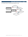
K-77 Safety contactor Troubleshooting (380-415V Only) . . . . . . . . . . . . . . . . . . . . . . . . . D-33
Return to Main Table of Contents . . . . . . . . . . . . . . . . . . . . . . . . . . . . . . . . . . . . . . ii
Troubleshooting Trees • Combitherm CT Express Technical Service Manual • D–1
troubleshooting trees
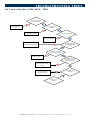
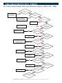
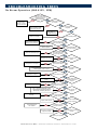
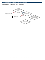
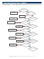
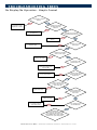
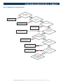
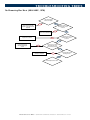
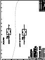
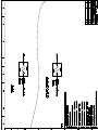
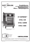
No Convection Heat (1PH)
Is N-6 oven temperature
probe below set point?
Yes
No
N-6 must be below set
point
Is K-41 contactor coil
energized?
Yes
No
L1/A1 from RBH X4/412,
L2/A2 from N7 high limit
Is K-41 contactor closing?
No
Replace K-41 contactor
L1/1 from TB 1, L2/3 from TB 3
Yes
Is voltage across terminals
1/3 on K-41 contactor?
No
Yes
Is voltage across terminals
2/4 on K-41 contactor?
No
Yes
Replace K-41 contactor
Is voltage across 3-4 and
2-5 on E-41 convection
elements?
Repair wiring between K-41
and E-41
Ohm out E-41 element and
replace if necessary
No
Yes
Is E-41 drawing current
on all legs?
No
Yes
Convection cycle is
operating
Troubleshooting Trees • Combitherm CT Express Technical Service Manual • D–2
troubleshooting trees
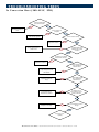
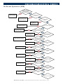
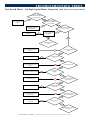
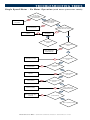
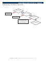
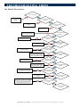
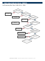
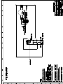
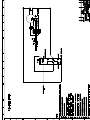
No Convection Heat (208-240V, 3PH)
Is N-6 oven temperature
probe below set point?
Yes
No
N-6 must be below set
point
Is K-41 contactor coil
energized?
Yes
No
L1/A1 from RBH X4/412,
L2/A2 from N7 high limit
Is K-41 contactor closing?
No
Replace K-41 contactor
Yes
Is L1/L2/L3 voltage across
terminals 2/4/6 on K-41
contactor?
No
L1/L2/L3 supplied from TB 1/2/3
Yes
Is voltage across terminals
1/3/5 on K-41 contactor?
No
Yes
Replace K-41 contactor
Is voltage across 3-4
and 2-5 and 1-6 on E-41
convection elements?
Repair wiring between K-41
and E-41
Ohm out E-41 element
and replace if necessary
No
Yes
Is E-41 drawing current
on all legs?
No
Yes
Convection cycle is
operating
Troubleshooting Trees • Combitherm CT Express Technical Service Manual • D–3
troubleshooting trees
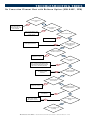
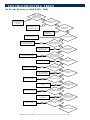
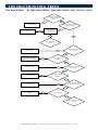
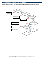
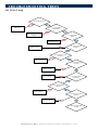
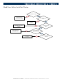
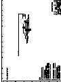
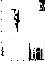
No Convection Heat (380-415V, 3PH)
Is N-6 oven temperature
probe below set point?
Yes
No
N-6 must be below set
point
Is K-41 contactor coil
energized?
Yes
No
L1/A1 from RBH X4/412,
L2/A2 from N7 high limit
Is K-41 contactor closing?
No
Replace K-41 contactor
L1/L2/L3 supplied from K-77
contactor 1/3/5
Yes
Is L1/L2/L3 voltage across
terminals 1/3/5 on K-41
contactor?
No
Yes
Is voltage across terminals
2/4/6 on K-41 contactor?
No
Yes
Replace K-41 contactor
Is there L1/L2/L3 voltage
across terminal 1 at
F10/11/12 fuses?
Repair wiring between K-42
and F10/11/12
Repair blown F10/11/12
fuse(s)
No
Yes
Is there L1/L2/L3 voltage
across terminal 2 at
F10/11/12 fuses?
No
Yes
Repair wiring between
F10/11/12 fuses and E-41
Is voltage across 3-4
and 2-5 and 1-6 on E-41
convection elements?
No
Yes
Ohm out E-41 element
and replace if necessary
Is E-41 drawing current on
all legs?
No
Yes
Convection cycle is
operating
Troubleshooting Trees • Combitherm CT Express Technical Service Manual • D–4
troubleshooting trees
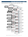
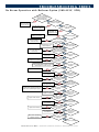
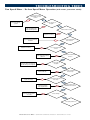
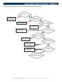
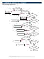
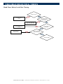
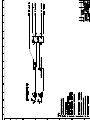
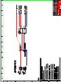
No Convection Element Heat with Retherm Option (208-240V, 3PH)
Is N-6 or B5 below set
point?
One must be below
set point in order for
convection elements to be
active in Retherm
Yes
No
Is K-41 contactor coil
energized?
Yes
No
L1/A1 from RBH X4/412, L2/A2
from N7 high limit through A2
on K-42 contactor
Is K-41 contactor closing?
No
Replace K-41 contactor
L1/L2 supplied from TB 1/3
Yes
Is L1/L2 voltage across
terminals 2/4 on K-41
contactor?
No
Yes
Is voltage across terminals
1/3 on K-41 contactor?
No
Yes
Replace K-41 contactor
Is K-42 contactor coil
energized?
A1/L1 supplied from RBH X4/410, A2/L2
supplied from N7 high limit through K-61
N/C contacts (if Browning Bar option)
No
Yes
Is L3 power at terminal 6
of K-42 contactor?
No
L3 supplied to K-41/6
from TB 5
Yes
Is L3 power at terminal 5 of
K-42 contactor?
No
Yes
Replace K-42 contactor
Is voltage across E-41
convection elements?
Repair wiring between
K-41 and E-41
Ohm out E-41 element
and replace if necessary
Yes
No
Is E-41 drawing current on
all legs?
No
Yes
Convection Retherm cycle
is operating
Troubleshooting Trees • Combitherm CT Express Technical Service Manual • D–5
troubleshooting trees
No Convection Element Heat with Retherm Option (380-415V, 3PH)
Is N-6 or B5 below set
point?
One must be below
set point in order for
convection elements to be
active in Retherm
Yes
No
Is K-41 contactor coil
energized?
Yes
No
L1/A1 from RBH X4/412,
L2/A2 from N7 high limit
through A2 on K-42 contactor
Is K-41 contactor closing?
No
Yes
Replace K-41 contactor
L1/L2 supplied from K-77
contactor
Is L1/L2 voltage across
terminals 1/3 on K-41
contactor?
No
Yes
Replace K-41 contactor
Is voltage across terminals
2/4 on K-41 contactor?
No
Yes
Repair wiring between K-42
and F10/11
Is there L1/L2 voltage
across terminal 1 at
F10/11 fuses?
No
Yes
A1/L1 supplied from RBH X4/410,
A2/L2 supplied from N7 high limit
through K-61 N/C contacts (if
Browning Bar option)
Is K-42 contactor coil
energized?
No
Yes
L3 supplied to K-41/6
from K-77 contactor
Is L3 power at terminal 5 of
K-42 contactor?
No
Yes
Replace K-42 contactor
No
Is L3 power at terminal 6 of
K-42 contactor?
Yes
Repair wiring between
K-42 and F12
Is there L3 voltage across
terminal 1 at F12 fuse?
No
Yes
Replace blown F12 fuse
Is there L3 voltage across
terminal 2 of F12 fuses?
No
Yes
Repair wiring between K-41
and E-41
Is voltage across E-41
convection elements?
No
Yes
Ohm out E-41 element and
replace if necessary
Is E-41 drawing current on
all legs?
No
Yes
Convection Retherm cycle
is operating
Troubleshooting Trees • Combitherm CT Express Technical Service Manual • D–6
troubleshooting trees
No Steam Operation (1PH)
Is water connected
to the oven, turned on and
operating at pressures
between 30-90 psig?
Yes
No
Connect water,
turn on, or correct
pressures and retest
Is controlling probe below
its set point?
Yes
No
Controlling probe must be
below set point for steam
production to take place
Is Y1 solenoid being
energized?
L1/A1 supplied from
RBH X4/408, L2
supplied from TB 12
Replace Y1 solenoid
No
Yes
Is Y1 solenoid opening?
No
Yes
Repair obstruction between Y1
and flow control valve inlet
Is water flowing from Y1
to flow control valve inlet?
No
Yes
Repair/replace flow control
valve as required
Is water flowing through
flow control valve?
No
Yes
Repair obstruction between flow
control valve and injection pipe
No
Is water flowing from
flow control valve outlet
to injection pipe inlet?
Yes
Repair/replace injection pipe
Is injection pipe clear of
debris?
No
Yes
Repair injection pipe/
disintegration box as required
No
Is water flowing into the
center of the fan wheel?
Yes
L1/A1 from RBH X4/412,
L2/A2 from N7 high limit
Is K-41 contactor coil
energized?
No
Yes
Replace K-41 contactor
No
Is K-41 contactor closing?
Yes
L1/1 from TB 1, L2/3
from TB 3
Is voltage across terminals
1/3 on K-41 contactor?
No
Yes
Replace K-41 contactor
No
Is voltage across terminals
2/4 on K-41 contactor?
Yes
Repair wiring between
K-41 and E-41
Is voltage across 3-4 and
2-5 on E-41 convection
elements?
No
Yes
Ohm out E-41 element and
replace if necessary
No
Is E-41 drawing current on
all legs?
Yes
Steam cycle is operating
Troubleshooting Trees • Combitherm CT Express Technical Service Manual • D–7
troubleshooting trees
No Steam Operation (208-240V, 3PH)
Is water connected
to the oven, turned on and
operating at pressures
between 30-90 psig?
Yes
No
Connect water, turn on,
or correct pressures
and retest
Is controlling probe below
its set point?
Yes
No
Controlling probe must be
below set point for steam
production to take place
Is Y1 solenoid being
energized?
No
L1/A1 supplied from
RBH X4/408, L2
supplied from TB 12
Replace Y1 solenoid
Yes
Is Y1 solenoid opening?
No
Yes
Repair obstruction between Y1
and flow control valve inlet
Is water flowing from Y1
to flow control valve inlet?
No
Yes
Repair/replace flow control
valve as required
Is water flowing through
flow control valve?
No
Yes
Repair obstruction between flow
control valve and injection pipe
No
Is water flowing from
flow control valve outlet
to injection pipe inlet?
Yes
Repair/replace injection pipe
Is injection pipe clear of
debris?
No
Yes
Repair injection pipe/
disintegration box as required
No
Is water flowing into the
center of the fan wheel?
Yes
L1/A1 from RBH X4/412,
L2/A2 from N7 high limit
Is K-41 contactor coil
energized?
No
Yes
Replace K-41 contactor
No
Is K-41 contactor closing?
Yes
L1/L2/L3 supplied from
TB 1/2/3
Is L1/L2/L3 voltage across
terminals 2/4/6 on K-41
contactor?
No
Yes
Replace K-41 contactor
No
Is voltage across terminals
1/3/5 on K-41 contactor?
Yes
Repair wiring between
K-41 and E-41
Is voltage across 3-4
and 2-5 and 1-6 on E-41
convection elements?
No
Yes
Ohm out E-41 element and
replace if necessary
No
Is E-41 drawing current on
all legs?
Yes
Steam cycle is operating
Troubleshooting Trees • Combitherm CT Express Technical Service Manual • D–8
troubleshooting trees
No Steam Operation with Retherm Option (208-240V, 3PH)
Is water connected
to the oven, turned on and
operating at pressures
between 30-90 psig?
Connect water,
turn on, or correct
pressures and retest
No
Yes
Is controlling probe below
its set point?
Yes
No
Controlling probe must be
below set point for steam
production to take place
Is Y1 solenoid being
energized?
No
L1/A1 supplied from
RBH X4/408, L2
supplied from TB 12
Replace Y1 solenoid
Yes
No
Is Y1 solenoid opening?
Yes
Repair obstruction between Y1
and flow control valve inlet
No
Is water flowing from Y1
to flow control valve inlet?
Yes
Repair/replace flow control
valve as required
Is water flowing through
flow control valve?
No
Yes
Repair obstruction between flow
control valve and injection pipe
Is water flowing from
flow control valve outlet
to injection pipe inlet?
No
Yes
Repair/replace injection pipe
Is injection pipe clear of
debris?
No
Yes
Repair injection pipe/
disintegration box as required
Is water flowing into the
center of the fan wheel?
No
Yes
L1/A1 from RBH X4/412, L2/A2 from N7 high
limit through A2 on K-42 contactor
Is K-41 contactor coil
energized?
No
Yes
Replace K-41 contactor
No
Is K-41 contactor closing?
Yes
L1/L2 supplied from
TB 1/3
No
Yes
Replace K-41 contactor
No
Is voltage across terminals
1/3 on K-41 contactor?
Yes
A1/L1 supplied from RBH X4/410, A2/L2
supplied from N7 high limit through K-61
N/C contacts (if Browning Bar option)
L3 supplied to K-41/6
from TB 5
No
Is L1/L2 voltage across
terminals 2/4 on K-41
contactor?
Is K-42 contactor coil
energized?
No
Yes
Is L3 power at terminal 6
of K-42 contactor?
Yes
Replace K-42 contactor
Is L3 power at terminal 5
of K-42 contactor?
No
Yes
Repair wiring between
K-41 and E-41
No
Is voltage across E-41
convection elements?
Yes
Ohm out E-41 element and
replace if necessary
Is E-41 drawing current
on all legs?
No
Yes
Steam cycle is operating
Troubleshooting Trees • Combitherm CT Express Technical Service Manual • D–9
troubleshooting trees
No Steam Operation (380-415V, 3PH)
Is water connected
to the oven, turned on and
operating at pressures
between 30-90 psig?
No
Yes
Is controlling probe below
its set point?
Connect water,
turn on, or correct
pressures and retest
Yes
No
Controlling probe must be
below set point for steam
production to take place
Is Y1 solenoid being
energized?
No
L1/A1 supplied from
RBH X4/408, L2
supplied from TB 12
Replace Y1 solenoid
Yes
No
Is Y1 solenoid opening?
Yes
Repair obstruction between Y1
and flow control valve inlet
No
Is water flowing from Y1
to flow control valve inlet?
Yes
Repair/replace flow control
valve as required
Is water flowing through
flow control valve?
No
Yes
Repair obstruction between flow
control valve and injection pipe
Is water flowing from
flow control valve outlet
to injection pipe inlet?
No
Yes
Repair/replace injection pipe
Is injection pipe clear of
debris?
No
Yes
Repair injection pipe/
disintegration box as required
Is water flowing into the
center of the fan wheel?
No
Yes
L1/A1 from RBH X4/412, L2/A2 from N7 high
limit through A2 on K-42 contactor
Is K-41 contactor coil
energized?
No
Yes
Replace K-41 contactor
No
Is K-41 contactor closing?
Yes
L1/L2 supplied from
TB 1/3
No
Yes
Replace K-41 contactor
No
Is voltage across terminals
1/3 on K-41 contactor?
Yes
A1/L1 supplied from RBH X4/410, A2/L2
supplied from N7 high limit through K-61
N/C contacts (if Browning Bar option)
L3 supplied to K-41/6
from TB 5
No
Is L1/L2 voltage across
terminals 2/4 on K-41
contactor?
Is K-42 contactor coil
energized?
No
Yes
Is L3 power at terminal 6
of K-42 contactor?
Yes
Replace K-42 contactor
Is L3 power at terminal 5
of K-42 contactor?
No
Yes
Repair wiring between
K-41 and E-41
No
Is voltage across E-41
convection elements?
Yes
Ohm out E-41 element and
replace if necessary
Is E-41 drawing current on
all legs?
No
Yes
Steam cycle is operating
T r o u b l e s h o o t i n g T r e e s • C o m b i t h e r m C T E x p r e s s T e c h n i c a l S e r v i c e M a n u a l • D – 10
troubleshooting trees
No Steam Operation with Retherm Option (380-415V, 3PH)
Connect water,
turn on, or correct
pressures and retest
Is water connected
to the oven, turned on and
operating at pressures
between 30-90 psig?
Yes
No
Is controlling probe
below its set point?
Yes
No
Controlling probe must be
below set point for steam
production to take place
Is Y1 solenoid being
energized?
L1/A1 supplied from
RBH X4/408, L2
supplied from TB 12
Replace Y1 solenoid
Repair obstruction
between Y1 and flow
control valve inlet
Is Y1 solenoid opening?
Yes
Is water flowing from
Y1 to flow control
valve inlet?
Yes
Repair/replace flow control
valve as required
No
Is water flowing through
flow control valve?
No
Yes
Is water flowing
from flow control valve outlet
to injection pipe inlet?
Yes
Repair/replace
injection pipe
Repair injection pipe/
disintegration box as required
Yes
No
No
Repair obstruction between
flow control valve and
injection pipe
No
No
Is water flowing
into the center of the
fan wheel?
No
L1/A1 from RBH X4/412, L2/A2 from N7 high
limit through A2 on K-42 contactor
Yes
Is injection pipe clear
of debris?
Yes
Is K-41 contactor coil
energized?
No
Yes
Replace K-41 contactor
No
Is K-41 contactor closing?
Yes
L1/L2 supplied from
K-77 contactor
Replace K-41 contactor
No
Repair wiring between
K-42 and F10/11
A1/L1 supplied from RBH X4/410, A2/L2
supplied from N7 high limit through K-61
N/C contacts (if Browning Bar option)
No
No
Repair wiring between
K-42 and F12
Replace blown F12 fuse
Is voltage across
terminals 2/4 on K-41
contactor?
Yes
Is there L1/L2
voltage across terminal 1
at F10/11 fuses?
Yes
No
Is K-42 contactor coil
energized?
Yes
L3 supplied to K-41/16
from K-77 contactor
Replace K-42 contactor
Is L1/L2 voltage across
terminals 1/3 on K-41
contactor?
Yes
No
No
Repair wiring between
K-41 and E-41
No
Is L3 power at
terminal 6 of K-42
contactor?
Yes
Yes
No
Is there L3 voltage
across terminal 2 at
F12 fuse?
Yes
Yes
No
Yes
Ohm out E-41 element and
replace if necessary
No
Is L3 power at
terminal 5 of K-42
contactor?
Is there L3 voltage
across terminal 1 at
F12 fuse?
Is voltage across
E-41 convection
elements?
Is E-41 drawing current
on all legs?
Yes
Steam cycle is operating
T r o u b l e s h o o t i n g T r e e s • C o m b i t h e r m C T E x p r e s s T e c h n i c a l S e r v i c e M a n u a l • D – 11
troubleshooting trees
Too Much Steam Production
Is steam bypass port
blocked?
No
Yes
Clear obstruction to steam
bypass port and retest
Is steam bypass hose
blocked?
No
Yes
Clear obstruction to steam
bypass hose and retest
Is B5 steam bypass probe
dirty or damaged?
Yes
Repair/replace as needed
Repair/replace low pressure relief
valve as required
No
Is low pressure relief valve
fully seated in the closed
position?
No
Yes
Is a closed system present?
Inspect clean out port on
condensate pan and ensure it is
completely closed and sealed
No
Yes
Operational
If problem persists contact
factory for assistance
T r o u b l e s h o o t i n g T r e e s • C o m b i t h e r m C T E x p r e s s T e c h n i c a l S e r v i c e M a n u a l • D – 12
troubleshooting trees
No Smoke
Is smoke icon selected?
No
Yes
Select smoke function and
start a cycle
Is the browning vent
closed?
Smoke will not function if
browning vent is open as detected
by browning vent switch
Yes
No
Is there voltage across terminal
1-6 at the smoke element?
No
L1/1 from RBH X3/306
through SK 3A Fuse (test
fuse) L2/6 from TB
Ohm out element and replace
if necessary
Yes
No
Is element drawing current?
Yes
Smoke cycle is operating
If still low or no smoke production taking
place refer to the operation/care manual for
proper operating procedures
T r o u b l e s h o o t i n g T r e e s • C o m b i t h e r m C T E x p r e s s T e c h n i c a l S e r v i c e M a n u a l • D – 13
troubleshooting trees
No Catalytic Converter (CC) Operation
Is there voltage across
terminal 1-6 at CC
element?
No
Yes
L1/1 from RBH X2/200
through CC 3A fuse (test
fuse) L2/6 from TB
Is CC element drawing
current?
Yes
No
Inspect vents inside oven
and ensure they are clear of
obstruction, Inspect catalyst
for integrity
Ohm out CC element,
replace if necessary
Yes
If all ok, CC is working
properly
T r o u b l e s h o o t i n g T r e e s • C o m b i t h e r m C T E x p r e s s T e c h n i c a l S e r v i c e M a n u a l • D – 14
troubleshooting trees
Two Speed Motor - No High Speed Motor Operation (with motor protection switch)
Is F-51 motor
protection switch (MPS) in
the start position?
No
Yes
Is there L1 power
supplied to terminal 21 of
K-52 contactor?
Reset switch and test
operation
Yes
No
L1 supplied to terminal 21
from RBH/X3/300
Replace faulty K-52
contactor
Is there L1 power at terminal
22 of K-52 contactor?
No
Is K-52 coil energized
and engaged
No
Yes
Yes
Unit is in low speed
operation
Repair wiring between K-52/22
and F-51/2
Is L1 power at terminal 2
of F-51?
No
Yes
Repair/replace F-51 MPS
No
Is L1 power at terminal 5
of F-51?
Yes
Repair wiring between F-51/5
and motor
Is L1 power at motor?
No
Yes
L1/14 from TB 16, L2/13 from N7
high limit through motor high limit
No
Is motor relay coil
energized?
Yes
Is L2 power at terminal 12
of motor relay?
No
L2/12 from TB 14/2
Yes
Replace motor relay
No
Is L2 power at terminal 8 of
motor relay?
Yes
Repair wiring between motor
relay and motor
Is there voltage across blue/
white wires at motor?
No
Yes
Ohm out motor and replace
if necessary
No
Is motor running?
Yes
High speed motor operation
is working
T r o u b l e s h o o t i n g T r e e s • C o m b i t h e r m C T E x p r e s s T e c h n i c a l S e r v i c e M a n u a l • D – 15
troubleshooting trees
Two Speed Motor - No High Speed Motor Operation (without motor protection switch)
is there L1 power supplied
to terminal 21 of K-52
contactor?
Yes
No
L1 supplied to terminal 21
from RBH/X3/300
Replace faulty K-52
contactor
Is there L1 power at terminal
22 of K-52 contactor?
No
Is K-52 coil energized
and engaged?
No
Yes
Yes
Unit is in low speed
operation
Repair wiring between K-52 and
motor blue wire
Is there L1 power at the blue
wire of the motor?
No
Yes
L1/14 from TB 16, L2/13 from N7
high limit through motor high limit
No
Is motor relay coil
energized?
Yes
Is L2 power at terminal 12
of motor relay?
No
L2/12 from TB 14/2
Yes
Replace motor relay
No
Is L2 power at terminal 8 of
motor relay?
Yes
Repair wiring between motor
relay and motor
Is there voltage across blue/
white wires at motor?
No
Yes
Ohm out motor and replace if
necessary
No
Is motor running?
Yes
High speed motor operation
is working
T r o u b l e s h o o t i n g T r e e s • C o m b i t h e r m C T E x p r e s s T e c h n i c a l S e r v i c e M a n u a l • D – 16
troubleshooting trees
Two Speed Motor - No Low Speed Motor Operation (with motor protection switch)
Is F-51 motor protection
switch (MPS) in the start
position?
No
Yes
Is K-52 contactor coil
energized?
Reset switch and test
operation
Yes
No
L1/A1 from RBH X3/304,
L2/A2 from N7 High limit
Is K-52 contactor closing?
No
Yes
Replace K-52 contactor
Repair wiring between K-52/A2
and K-52/4
Is L1 power at terminal 4 of
K-52 contactor?
No
Yes
Replace K-52 contactor
Is L1 power at terminal 3
of K-52?
No
Yes
Repair wiring between K-52/3
and motor
Is L1 power at black wire
on motor?
No
Yes
L1/14 from TB 16, L2/13 from N7
high limit through motor high limit
No
Is motor relay coil
energized?
Yes
L2/12 from TB 14/2
Is L2 power at terminal 12
of motor relay?
No
Yes
Replace motor relay
No
Is L2 power at terminal 8 of
motor relay?
Yes
Repair wiring between
motor relay and motor
Is there voltage across
black/white wires at motor?
No
Yes
Ohm out motor and replace
if necessary
No
Is motor running?
Yes
Low speed operation is ok
T r o u b l e s h o o t i n g T r e e s • C o m b i t h e r m C T E x p r e s s T e c h n i c a l S e r v i c e M a n u a l • D – 17
troubleshooting trees
Two Speed Motor - No Low Speed Motor Operation (without motor protection switch)
Is K-52 contactor coil
energized?
Yes
No
L1/A1 from RBH X3/304,
L2/A2 from TB 13-4
Is K-52 contactor closing?
No
Yes
Replace K-52 contactor
Repair wiring between K-52/A2
and K-52/4
Is L1 power at terminal 4 of
K-52 contactor?
No
Yes
Replace K-52 contactor
Is L1 power at terminal 3
of K-52?
No
Yes
Repair wiring between K-52/3
and motor
Is L1 power at black wire
on motor?
No
Yes
L1/14 from TB 16, L2/13 from N7
high limit through motor high limit
No
Is motor relay coil energized?
Yes
L2/12 from TB 14/2
Is L2 power at terminal 12
of motor relay?
No
Yes
Replace motor relay
No
Is L2 power at terminal 8 of
motor relay?
Yes
Repair wiring between
motor relay and motor
Is there voltage across
black/white wires at motor?
No
Yes
Ohm out motor and replace
if necessary
No
Is motor running?
Yes
Low speed operation is ok
T r o u b l e s h o o t i n g T r e e s • C o m b i t h e r m C T E x p r e s s T e c h n i c a l S e r v i c e M a n u a l • D – 18
troubleshooting trees
Single Speed Motor - No Motor Operation (with motor protection switch)
Is F-51 motor
protection switch (MPS) in
the start position?
Yes
No
Is there L1 power
supplied to terminal 21 of
K-52 contactor?
Reset switch and
test operation
Yes
No
L1 supplied to terminal
21 from RBH/X3/300
Replace faulty K-52
contactor
Is there L1 power at
terminal 22 of K-52 contactor?
No
Is K-52 coil energized
and engaged?
No
Yes
Yes
Unit is in low speed
operation
Is L1 power at terminal 2
of F-51?
No
Repair wiring between
K-52/22 and F-51/2
Repair/replace F-51 MPS
Yes
Is L1 power at terminal 5
of F-51?
No
Yes
Repair wiring between
F-51/43 and motor
No
Is L1 power at blue wire
on motor?
Yes
L2/43 supplied from N-7
High limit
Is L2 power at terminal
43 of F-51?
No
Yes
Repair wiring between
F-51/5 and motor
No
Is L2 power at white wire
on motor?
Yes
Is there voltage across
blue/white wires at motor?
No
Repair motor wiring
Yes
Ohm out motor and replace
if necessary
No
Is motor running?
Yes
Motor is operating correctly
T r o u b l e s h o o t i n g T r e e s • C o m b i t h e r m C T E x p r e s s T e c h n i c a l S e r v i c e M a n u a l • D – 19
troubleshooting trees
S in gl e S p e e d M otor - No M otor Oper a tion (without motor protection switch)
Is there L1 power at the blue
wire of the motor?
Yes
No
Is motor relay coil
energized?
L1 supplied to blue wire
from RBH/X3/300
Yes
No
L1/14 from TB 16, L2/13
from N7 high limit through
motor high limit
Is L2 power at terminal 12
of motor relay?
No
Yes
L2/12 from TB 14/2
Is L2 power at terminal 8
of motor relay?
No
Replace motor relay
Yes
Repair wiring between motor
relay and motor
No
Is there voltage across blue/
white wires at motor?
Yes
Ohm out motor and replace
if necessary
No
Is motor running?
Yes
Motor is working
T r o u b l e s h o o t i n g T r e e s • C o m b i t h e r m C T E x p r e s s T e c h n i c a l S e r v i c e M a n u a l • D – 20
troubleshooting trees
No Display/Control not powering on (Unit Dead)
Is voltage across L1/L2 at
main TB?
Yes
No
Is voltage across terminal
1/F1 and terminal 1/F2
6.3A fuses?
Check cord/plug/main
circuit breaker – Install/
Repair/Reset as needed
Yes
No
Repair wiring between
main TB and F/1F2 fuses
Is voltage across terminal 2/F1
and terminal 2/F2 6.3A fuses?
No
Replace blown F1/F2
fuses(s)
Repair wiring between F1/F2
and Power Supply
Yes
Is voltage across L1/N at
power supply?
No
Yes
Is 12 VDC across terminals
V+ and V- at power supply?
No
Yes
Replace power supply
Is 12 VDC across display
(LCD) terminals DB3 and
DB1?
Repair wiring between power
supply and LCD
Test On/Off board cable for
continuity. If cable ok, replace
display board
No
Yes
Is there 12 VDC across
pin 1-2 on On/Off board?
No
Yes
Test On/Off board On = Temporary switch between 1-3
Off = temporary switch between 1-4
T r o u b l e s h o o t i n g T r e e s • C o m b i t h e r m C T E x p r e s s T e c h n i c a l S e r v i c e M a n u a l • D – 21
troubleshooting trees
No Display/No Operation - Simple Control
Is voltage across L1/L2 at
main TB?
Yes
No
Check cord/plug/main
circuit breaker – Install/
Repair/Reset as needed
Is voltage across terminal
1/F1 and terminal 1/F2
6.3A fuses?
Yes
No
Repair wiring between main TB
and F1/F2 fuses
Is voltage across terminal 2/F1
and terminal 2/F2 6.3A fuses?
No
No replace blown F1/F2
fuses(s)
Repair wiring between F1/F2
and power supply
Yes
Is voltage across L1/N at
power supply?
No
Yes
Is 12 VDC across terminals V+
and V- at power supply?
No
Yes
Replace power supply
Is 12 VDC across RBL
terminals X8-pins 1-2?
Repair wiring between power
supply and RBL
Correct cable and retest
No
Yes
Is the ribbon cable securely
seated at the RBL and the
display board?
No
Yes
Is there continuity across
all ribbon cable connection
points end-to-end?
No
Yes
Replace ribbon cable
Is there 12 VDC at pins
31/32 and 33/34 on the
ribbon cable?
Replace relay board
Test On/Off board cable
for continuity. If cable ok,
replace display board
Yes
No
Is there 12 VDC across pin
1-2 on On/Off board?
No
Yes
Test On/Off board On = Temporary switch between 1-3
Off = temporary switch between 1-4
Replace On/Off board as needed, if On/Off
board tests ok, replace display board
T r o u b l e s h o o t i n g T r e e s • C o m b i t h e r m C T E x p r e s s T e c h n i c a l S e r v i c e M a n u a l • D – 22
troubleshooting trees
No Browning Vent Motor Operation
Is there 12 VDC across
vent motor wiring?
No
Yes
V-1 from RBL X8/2, V+
from RBL X5/5
Is vent motor turning?
No
Yes
Is motor stopping after
rotating 90º?
Replace vent motor
Inspect/test vent motor switch and wiring
between vent motor switch and RBL.
Switch is open when vent is closed and
closed when vent is open.
Replace vent assembly if all wiring ok and
vent motor continues to rotate.
No
Yes
Vent motor is operating
properly.
T r o u b l e s h o o t i n g T r e e s • C o m b i t h e r m C T E x p r e s s T e c h n i c a l S e r v i c e M a n u a l • D – 23
troubleshooting trees
No Oven Lamp
Is oven lamp fully intact?
Yes
No
Replace lamp
Is L1 power at RBH
terminal X4/416?
Yes
No
Repair wiring between RBH/416
and TB 17/3
Is L1 power at RBH
X4/414?
No
Ensure LED D01 is lit,
replace RBH if necessary
Repair wiring between
RBH/414 and F3/1
Yes
Is L1 power at F3 2A fuse
terminal 1?
No
Yes
Is L1 power at F3 2A fuse
terminal 2?
No
Yes
Replace blown F3 fuse
Is L1 power at oven lamp
receptacle?
Repair wiring between
F3/2 and oven lamp
No
Yes
Repair wiring between
F4/1 and TB 12
Is L2 power at F4 2A
fuse terminal 1?
No
Yes
Is L2 power at F4 2A fuse
terminal 2?
No
Yes
Replace blown fuse
Is L2 power at oven lamp
receptacle?
Repair wiring between
F2/2 and oven lamp
No
Yes
Replace receptacle and/or
oven lamp
T r o u b l e s h o o t i n g T r e e s • C o m b i t h e r m C T E x p r e s s T e c h n i c a l S e r v i c e M a n u a l • D – 24
troubleshooting trees
No Condensate Injection (E15 error code)
Is B3 probe above 190ºF (88ºC)?
Yes
No
B3 must be above 190ºF (88ºC)
Is voltage across the coil
of the Y2 solenoid?
L1/A1 supplied from RBH
X2/210, L2/A2 supplied
from TB 12
Yes
No
Is Y2 solenoid opening?
No
Ensure water pressure
does not exceed 90 psi.
Replace Y2 solenoid
Repair obstruction between Y2
solenoid and the condensate
injection nozzle
Yes
Is water flowing to
condensate injection
nozzle?
No
Yes
Is water flowing into the
condensate pan?
Repair obstruction in
condensate injection nozzle
No
Yes
Is clean out port on
condensate pan closed?
Close clean out port and retest
No
Yes
Inspect B3 probe, repair/
clean/replace as required
T r o u b l e s h o o t i n g T r e e s • C o m b i t h e r m C T E x p r e s s T e c h n i c a l S e r v i c e M a n u a l • D – 25
troubleshooting trees
No Cleaning Operation
Is water connected to the oven,
turned on and operating at
pressures between 30-90 psig?
Yes
No
Connect water,
turn on, or correct
pressures and retest
Is cleaning pump being
energized?
Yes
No
L1 supplied from RBH X2/208,
L2 supplied from TB 12
Is cleaning pump
operating?
No
Inspect pump inlet for
blockage. Repair blockage and/
or replace pump as required
Repair obstruction in hose
between pump and injection pipe
Yes
Is water/chemical flowing
between pump and
injection pipe?
No
Yes
Is injection pipe clear
of debris?
No
Yes
Repair/replace injection pipe
Is clean out port on
condensate pan closed?
Close clean out port and retest
No
Yes
L1/A1 supplied from X2/216,
L2/A2 supplied from TB 12
Is Y3 rinse solenoid
energized?
No
Yes
Is Y3 rinse solenoid
opening?
Ensure water pressure does
not exceed 90 psi.
Replace Y3 solenoid
No
Repair obstruction in hose
between Y3 and injection pipe
Yes
Is water flowing from
Y3 solenoid to the
injection pipe?
No
Yes
Pump and Rinse solenoid
are operating*
*Refer to operation/care manual for best
practices regarding cleaning procedures
T r o u b l e s h o o t i n g T r e e s • C o m b i t h e r m C T E x p r e s s T e c h n i c a l S e r v i c e M a n u a l • D – 26
troubleshooting trees
No Cooling Fan Operation
Is L1 power at RBH
terminal X4/416?
Yes
No
No repair wiring between
RBH/416 and TB 17/3
Is L1 power at RBH
X4/414?
Yes
No
Ensure LED D01 is lit,
replace RBH if necessary
Is L1 power at TB 15?
No
Repair wiring between TB
15 and RBH X4/414
Repair wring between TB 15
and fan thermal switch
Yes
Is L1 power at fan
thermal switch?
No
Yes
Is L1 power going through
the fan thermal switch?
Thermal switch closes at 130ºF
(54ºF). If above 130ºF (54ºF),
replace thermal switch
No
Yes
Is L1 power at each
cooling fan motor?
Repair wiring between thermal
switch and cooling fan motors
L2 supplied from TB 12
No
Yes
Is L2 power at each
cooling fan motor?
No
Yes
Confirm voltage across
motor wires and repair/
replace cooling fan motors
as required
T r o u b l e s h o o t i n g T r e e s • C o m b i t h e r m C T E x p r e s s T e c h n i c a l S e r v i c e M a n u a l • D – 27
troubleshooting trees
No Hood Operation
Is L1 power at TB 16?
Yes
No
Is L1 power at F5 5A fuse
terminal 2?
L1 supplied from RBH
X4/414
Yes
No
Repair wiring between TB
16 F5/2
Is L1 power at F5 5A fuse
terminal 1?
No
Yes
Replace blown fuse
Repair wring between F5 fuse
and hood switch terminal 4
Is L1 power at hood switch
terminal 4?
No
Yes
Is L1 power at hood switch
terminal 3?
No
Replace faulty hood switch
Yes
Install hood filters, close door
and retest
Are hood filters installed
and the hood door
closed?
No
Yes
Repair wring between hood switch
terminal 3 and FSW1
No
Is L1 power at common
terminal of FSW1?
Yes
Ensure safety switch is being
depressed by the filter. Realign
and/or replace FSW1 As required
Is L1 power at N/O terminal
of FSW1?
No
Yes
Repair wring between FSW1
N/O and FSW2 Common
No
Is L1 power at common
terminal of FSW2?
Yes
Ensure safety switch is being
depressed by the filter. Realign
and/or replace FSW2 As required
Is L1 power at N/O terminal
of FSW2?
No
Yes
L1 is supplied from FSW2 N/O open,
L2 supplied from TB 19. Repair
wiring/ replace motor as required
No
Is there voltage at hood fan
and is hood fan operating?
Yes
Clean/replace filter(s) as
required
Are filters clean (less than
25% blockage)?
No
Yes
Test pressure at switch (.25” w.c required
for switch to close). If pressure not present,
inspect filters and pressure tube between
hood cavity and hood pressure switch
No
Is hood pressure switch
closing?
Yes
Hood is operating
properly
T r o u b l e s h o o t i n g T r e e s • C o m b i t h e r m C T E x p r e s s T e c h n i c a l S e r v i c e M a n u a l • D – 28
troubleshooting trees
Hood Door Safety Latch Not Closing
Is Combi door closed?
Yes
No
Combi door must be
closed for latch to engage
Is Combi door switch
closed?
No
Replace/repair door switch
as required
Repair/replace door switch
as required
Yes
Is 0 VDC across RBL
X2/5-6?
No
Yes
12 VDC supplied from
RBL X6 pins 1 and 2
No
Is there 12 VDC at door
safety latch solenoid?
Yes
Repair/replace solenoid/latch
as required
No
Is solenoid engaging
the latch?
T r o u b l e s h o o t i n g T r e e s • C o m b i t h e r m C T E x p r e s s T e c h n i c a l S e r v i c e M a n u a l • D – 29
troubleshooting trees
Hood Door Safety Latch Not Closing
Is Combi door open?
Yes
No
Door handle must be
opened
Has the door handle
been open for more than
45 seconds?
No
The door latch releases based
upon a timer. Wait a full 60
seconds for the latch to release
Replace/repair door switch
as required
Yes
Is there 12 VDC across
RBL X2/5-6?
No
Yes
Replace faulty latch
solenoid assembly
No
Is there 12 VDC at door
safety latch solenoid?
Yes
Replace faulty RBL
T r o u b l e s h o o t i n g T r e e s • C o m b i t h e r m C T E x p r e s s T e c h n i c a l S e r v i c e M a n u a l • D – 30
troubleshooting trees
No Browning Bar Heat (208-240V, 3PH)
Is K-61 Browning Bar
contactor energized?
Yes
No
A1/L1 supplied from RBH/
X3/306, L2 supplied from N7
high limit
Is L1/L2/L3 power across
terminals 1/3/5 on K-61
contactor?
No
Repair wiring between
1/3/5 on K-61 and main TB
Replace K-61 contactor
Yes
Is L1/L2/L3 power across
terminals 2/4/6 on K-61
contactor?
No
Yes
Repair wiring between
K-61 and Browning Bar
element
No
Is power across terminals
1/6 and 2/5 and 3/4 on
E-61 browning element?
Yes
Ohm out Browning Bar element
and replace if required
Is Browning Bar element
drawing current?
No
Yes
Browning Bar element active
T r o u b l e s h o o t i n g T r e e s • C o m b i t h e r m C T E x p r e s s T e c h n i c a l S e r v i c e M a n u a l • D – 31
troubleshooting trees
No Browning Bar Heat (380-415V, 3PH)
Is K-61 Browning Bar
contactor energized?
Yes
No
A1/L1 supplied from RBH/
X3/306, L2 supplied from
N7 high limit
Is L1/L2/L3 power across
terminals 1/3/5 on K-61
contactor?
Yes
No
L1/L2/L3 supplied from
K-77 contactor
Is L1/L2/L3 power across
terminals 2/4/6 on K-61
contactor?
No
Replace K-61 contactor
Repair wiring between K-61 and
F20/21/22 fuses
Yes
Is L1/L2/L3 power across
terminal 1 of F20/21/22 fuses?
No
Yes
Is there L1/L2/L3 power
across terminal 2 of
F20/21/22?
No
Yes
Replace blown fuse(s)
Is power across terminals
1/6 and 2/5 and 3/4 on E-61
browning element?
Repair wiring between F20/21/22
and Browning Bar element
Ohm out Browning Bar element
and replace if required
No
Yes
Is Browning Bar element
drawing current?
No
Yes
Browning Bar element active
T r o u b l e s h o o t i n g T r e e s • C o m b i t h e r m C T E x p r e s s T e c h n i c a l S e r v i c e M a n u a l • D – 32
troubleshooting trees
K-77 Safety Contactor Troubleshooting (380-415V only)
Is K-77 contactor coil
energized?
L1/A1 supplied from TB 16, TB 16
supplied from RBH X4/414, L2/A2
supplied from N7 high limit
Yes
No
Is L1/L2/L3 power across
terminals 2/4/6 on K-77
contactor?
No
Repair wiring
Replace K-77 contactor
Yes
Is L1/L2/L3 power across
terminals 1/3/5 on K-77
contactor?
No
Yes
K-77 is operating correctly
T r o u b l e s h o o t i n g T r e e s • C o m b i t h e r m C T E x p r e s s T e c h n i c a l S e r v i c e M a n u a l • D – 33
SERVICE PARTS
PARTS INFORMATION
Exterior . . . . . . . . . . . . . . . . . . . . . . . . . . . . . . . . . . . . . . . . . . . . . . . . . . . . . .
Rear and Bottom Service Parts . . . . . . . . . . . . . . . . . . . . . . . . . . . . . . . . . . . . . .
Painted Panels . . . . . . . . . . . . . . . . . . . . . . . . . . . . . . . . . . . . . . . . . . . . . . . . .
Right Hand Door Assembly . . . . . . . . . . . . . . . . . . . . . . . . . . . . . . . . . . . . . . . .
Left Hand Door Assembly . . . . . . . . . . . . . . . . . . . . . . . . . . . . . . . . . . . . . . . . .
Field Retrofit Kit: Bumper With Threads . . . . . . . . . . . . . . . . . . . . . . . . . . . . . . .
Interior View . . . . . . . . . . . . . . . . . . . . . . . . . . . . . . . . . . . . . . . . . . . . . . . . . . .
Top Interior and Right Side . . . . . . . . . . . . . . . . . . . . . . . . . . . . . . . . . . . . . . . .
Interior Rear . . . . . . . . . . . . . . . . . . . . . . . . . . . . . . . . . . . . . . . . . . . . . . . . . . .
Directional Panel Assembly . . . . . . . . . . . . . . . . . . . . . . . . . . . . . . . . . . . . . . . .
Combitherm Motor . . . . . . . . . . . . . . . . . . . . . . . . . . . . . . . . . . . . . . . . . . . . . .
Electrical Cord & Routing . . . . . . . . . . . . . . . . . . . . . . . . . . . . . . . . . . . . . . . . .
Plumbing . . . . . . . . . . . . . . . . . . . . . . . . . . . . . . . . . . . . . . . . . . . . . . . . . . . . .
Control Assembly - Simple (Before 09/14) . . . . . . . . . . . . . . . . . . . . . . . . . . . . .
Control Assembly - Simple (After 09/14) . . . . . . . . . . . . . . . . . . . . . . . . . . . . . .
Control Assembly - Express Touch . . . . . . . . . . . . . . . . . . . . . . . . . . . . . . . . . . .
Touch Control Replacement Kit . . . . . . . . . . . . . . . . . . . . . . . . . . . . . . . . . . . . .
Catalytic Converter . . . . . . . . . . . . . . . . . . . . . . . . . . . . . . . . . . . . . . . . . . . . . .
Broiling Element . . . . . . . . . . . . . . . . . . . . . . . . . . . . . . . . . . . . . . . . . . . . . . . .
Condensor Tank . . . . . . . . . . . . . . . . . . . . . . . . . . . . . . . . . . . . . . . . . . . . . . . .
Lamp Assembly . . . . . . . . . . . . . . . . . . . . . . . . . . . . . . . . . . . . . . . . . . . . . . . . .
Inner Tube & Wash Nozzle . . . . . . . . . . . . . . . . . . . . . . . . . . . . . . . . . . . . . . . .
Smoker Chip Tray Assembly . . . . . . . . . . . . . . . . . . . . . . . . . . . . . . . . . . . . . . .
Optional Single Point Probe Assembly . . . . . . . . . . . . . . . . . . . . . . . . . . . . . . . .
Optional Hand Shower Assembly . . . . . . . . . . . . . . . . . . . . . . . . . . . . . . . . . . . .
Electrical Assembly . . . . . . . . . . . . . . . . . . . . . . . . . . . . . . . . . . . . . . . . . . . . . .
Ventless Hood Assembly . . . . . . . . . . . . . . . . . . . . . . . . . . . . . . . . . . . . . . . . . .
E-2
E-3
E-4
E-5
E-6
E-7
E-8
E-9
E-10
E-11
E-12
E-13
E-14
E-16
E-17
E-18
E-19
E-20
E-21
E-22
E-23
E-23
E-24
E-25
E-26
E-27
E-33
Return to Main Table of Contents . . . . . . . . . . . . . . . . . . . . . . . . . . . . . . . . . . . . . . ii
Service Parts • Combitherm CT Express Technical Service Manual • E–1
PARTS INFORMATION
EXTERIOR VIEW
27
25
26
4
SECTION D-D
18
A
5
19
17
16
20
21
24
15
3
14
1
D
D
2
13
22
7
A
Item
Part
1
2
3
4
5
6
7
8
9
10
11
12
13
14
15
16
SC-29871
1012981
1012382
5014726
BU-28391
CL-22196
ST-22193
SD-22194
WS-22195
WS-22302
NU-22292
5014033
SR-29602
LT-29636
SH-2903
1012798
6
12
23
Description
8
9
11 10
SECTION A-A
Screw, #8 x 1/2" Hex Flg
Cover, Element Splash
Bracket, Motor Mount
Weld Assembly, Vent Tube
Bushing, Socket, Membrane
Clip, Holding, M6
Stud, M6 x 27mm, 1/4 Turn
Spring, M6 x 48, Safety
Washer, Safety, Steel
Washer, Split Lock
Nut, M8-1.25, Hex, 18-8, Din #934
Drip Tray, Weld Assembly
Side Rack, Wire, S/S
Latch, Door, Dog
Shelf
Deflector Strip
7
Qty.
Item
Part
47
1
1
1
1
4
4
4
4
1
1
1
2
1
2
1
17
18
19
20
1012295
SC-22281
5015470
1012300
1012301
SC-22926
SC-22281
1012822
1012821
5014123
1012268
1013024
1012637
DA-2943
WS-29885
21
22
23
24
25
26
27
28*
Description
Bracket, Gasket Corner Channel
Screw, M5 x 0.81 x 16mm Flat
Insulation Kit
Plate, Hinge Door, Upper, RH
Plate, Hinge Door, Upper, LH
Screw, M5 x 0.8 x 16mm, Hex
Screw, M5 x 0.8 x 16mm Flat
Plate, Hinge Door, Lower, LH
Plate, Hinge Door, Lower, RH
Gasket, Door
Panel, Side Access, S/S
Panel, Side Access, Painted (specify color)
Bracket, Air Tunnel
Drain Screen Assembly
Washer, Nylon, For 5/16"
Service Parts • Combitherm CT Express Technical Service Manual • E–2
Qty.
1
3
1
1
1
3
2
1
1
1
2
2
1
1
1
PARTS INFORMATION
REAR & BOTTOM SERVICE PARTS
1
15
14
2
13
Rear View
3
4
12
11
5
10
9
Item
1
2
3
4
5
6
7
8
Part
1012266
PB-29664
HL-29741
1012268
HO-29669
VA-29646
PB-35228
1012645
Description
Panel, Top Access, S/S**
Plumbing, Hand Sprayer
Holder, Hand Sprayer
Panel, Side Access, S/S**
Hose, Hand Sprayer
Valve, Hand Sprayer Shut-off
Plumbing, 3/4" GHT (M) to 1/2" NPT (F)
Bracket, Mount Shut-off Valve
Qty.
1
1
1
1
1
1
1
1
Item
9
10
11
12
13
14
15
8
Part
1013370
1013359
CP-29648
BU-34977
5017990
1015490
BT-26884
7
6
Left Side View
Description
Panel, Bottom Access
Cover, Condenser Tank
Cap, Push-on, Fits 1-1/4" OD
Cable Gland, M32, Black
Back Panel with Inserts
Air Vent
Tether bracket (not standard on all models)
** See following page for painted panel part numbers
Service Parts • Combitherm CT Express Technical Service Manual • E–3
Qty.
1
1
1
1
1
1
1
PARTS INFORMATION
PAINTED PANELS
Item
A
B
C
D
E
F
G
H
I
J
Description
Panel, Cover, Sensor
Black
Brown
Burgundy
Custom
Red
White
Panel, Enclosure, Base Black
Custom
Brown
Burgundy
Red
White
Panel, Enclosure, Top
Black
Brown
Burgundy
Custom
Red
White
Panel, Side Access Black
Brown
Burgundy
Custom
Red
White
Panel, Spot, Control, Simple
Black
Brown
Burgundy
Custom
Red
White
Panel, Spot, Control, Touch, LH
Black
Brown
Burgundy
Custom
Red
White
Panel, Spot, Control, Touch, , RH
Black
Brown
Burgundy
Custom
Red
Panel, Spot, Cover, Access
Black
Brown
Burgundy
Custom
Red
White
Panel, Spot, Enclosure
Black
Brown
Burgundy
Custom
Red
White
Panel, Spot, Hndl Mnt, LH Door
Black
Brown
Burgundy
Custom
Red
White
Part Number
PE-35548
PE-35552
PE-35549
PE-35553
PE-35550
PE-35551
PE-35536
PE-35541
PE-35540
PE-35537
PE-35538
PE-35539
PE-35542
PE-35546
PE-35543
PE-35547
PE-35544
PE-35545
PE-35524
PE-35528
PE-35525
PE-35529
PE-35526
PE-35527
PE-35584
PE-35588
PE-35585
PE-35589
PE-35586
PE-35587
PE-35590
PE-35594
PE-35591
PE-35595
PE-35592
PE-35593
PE-35554
PE-35558
PE-35555
PE-35559
PE-35556
PE-35632
PE-35636
PE-35633
PE-35637
PE-35634
PE-35635
PE-35626
PE-35630
PE-35627
PE-35631
PE-35628
PE-35629
PE-35602
PE-35606
PE-35603
PE-35607
PE-35604
PE-35605
Item
K
L
M
N
O
P
Q
R
S
T
Panel Color
Panel, Spot, Hndl Mnt, RH Door
Black
Brown
Burgundy
Custom
Red
White
Panel, Spot/Weld, Touch Control, LH
Black
Brown
Burgundy
Custom
Red
White
Panel, Spot/Weld, Touch Control, RH
Black
Brown
Burgundy
Custom
Red
White
Panel, Top Access Black
Brown
Burgundy
Custom
Red
White
Panel, Weld, Door, LH
Black
Brown
Burgundy
Custom
Red
White
Panel, Weld, Door, RH
Black
Brown
Burgundy
Custom
Red
White
Panel, Weld, Outer Shell, LH
Black
Brown
Burgundy
Custom
Red
White
Panel, Weld, Outer Shell, RH
Black
Brown
Burgundy
Custom
Red
White
Panel, Weld/Spot, Door, LH
Black
Brown
Burgundy
Custom
Red
White
Panel, Weld/Spot, Door, RH
Black
Brown
Burgundy
Custom
Red
White
Service Parts • Combitherm CT Express Technical Service Manual • E–4
Part Number
PE-35596
PE-35600
PE-35597
PE-35601
PE-35598
PE-35599
PE-35614
PE-35618
PE-35615
PE-35619
PE-35616
PE-35617
PE-35608
PE-35612
PE-35609
PE-35613
PE-35610
PE-35611
PE-35530
PE-35534
PE-35531
PE-35535
PE-35532
PE-35533
PE-35578
PE-35582
PE-35579
PE-35583
PE-35580
PE-35581
PE-35572
PE-35576
PE-35573
PE-35577
PE-35574
PE-35575
PE-35566
PE-35570
PE-35567
PE-35571
PE-35568
PE-35569
PE-35560
PE-35564
PE-35561
PE-35565
PE-35562
PE-35563
PE-35638
PE-35642
PE-35639
PE-35643
PE-35640
PE-35641
PE-35620
PE-35624
PE-35621
PE-35625
PE-35622
PE-35623
PARTS INFORMATION
RIGHT HAND DOOR ASSEMBLY
Item
A
Description
Weld Assembly, Right Hand Door
Black
Brown
Burgundy
Custom
Red
White
Part Number
5015467
5015759
5015468
5015469
5015757
5015758
2
3
1
4
5
6
SPOT ASSY,
HANDLE MOUNT
SEE SHOP ORDER
DOOR HANDLE
SCREWS SHOULD
BE TIGHTENED TO
16 INCH-POUNDS
15
14
8
9
7
11
10
11
13
12
WELD ASSY, DOOR
SEE SHOP ORDER
Right Hand Door Assembly - 5015466
Item
1
2
3
4
5
6
7
8
9
10
11
12
13
14
15
16
Part
1007698
MA-25734
SC-22273
WS-22300
SC-29735
WS-22301
5013647
1012299
RI-27108
GL-29868
SP-36060
5014392
5015462
HD-29635
TA-25125
5015005
*NOT SHOWN
Description
Cover, Door Magnet, Single
Magnet, Door, AR-7E, Black
Screw, M4 x 0.7mm Pan
Washer, M4 Split Lock
Screw, M5 x 0.8 x 35mm Pan
Washer, M5 Split Lock S/S 18-8
Assembly, Inner Glass Right Hand Door
Clip, Inner Glass Right Hand Door
Rivet, Sealed
Glass, Outer, Door
Spacer, Inner Glass Table Top
Spot, Assembly, Handle Mount S/S
Spot Assembly, Door Right Hand S/S
Handle, Door, Pendulum
Tape, Duplomont 5'
Assembly, Latch
Qty.
1
1
3
3
3
3
1
1
1
1
2
1
1
1
1
1
A
USE LOCKTITE
3
4
16
Right Hand Door Assembly
with Ventless Hood - 5015466
Service Parts • Combitherm CT Express Technical Service Manual • E–5
TOLERANCE: UNLESS SPECIF
PARTS INFORMATION
LEFT HAND DOOR ASSEMBLY
Item
A
Description
Weld Assembly, Right Hand Door
Black
Brown
Burgundy
Custom
Red
White
Part Number
5014749
5015744
5014800
5014801
5015742
5015743
9
11
13
10
1
12
6
8
2
4
4
6
WELD ASSY, DOOR
SEE SHOP ORDER
3
5
7
SPOT ASSY, HANDLE MOUNT
SEE SHOP ORDER
DOOR HANDLE SCREWS SHOULD
BE TIGHTENED TO 16 INCH-POUNDS
Left Hand Door Assembly - 5014748
Item
1
2
3
4
5
6
7
8
9
10
11
12
13
14
Part
5014828
SC-29735
WS-22301
1013174
RI-27108
SP-36060
HD-29635
TA-25125
GL-29868
1007698
MA-25734
SC-22273
WS-22300
5015005
*NOT SHOWN
Description
Assembly, Inner Glass Left Hand Door
Screw, M5 x 0.8 x 35mm Pan
Washer, M5 Split Lock S/S 18-8
Clip, Inner Glass Left Hand Door
Rivet, Sealed
Spacer, Inner Glass Table Top
Handle, Door, Pendulum
Tape, Duplomont 5'
Glass, Outer, Door
Cover, Door Magnet, Single
Magnet, Door, AR-7E, Black
Screw, M4 x 0.7 x 10mm Pan
Washer, Split Lock
Assembly, Latch
Qty.
1
3
3
1
1
2
1
1
1
1
1
2
2
1
A
DETAIL A
2
13
14
Left Hand Door Assembly
with Ventless Hood - 5015584
Service Parts • Combitherm CT Express Technical Service Manual • E–6
PARTS INFORMATION
FIELD RETROFIT KIT: BUMPER WITH THREADS
5
1
2 SEE NOTE #3
2X .3020" (0.01mm)
SIZE “N” DRILL ITEM 4
4
DETAIL A
3 SEE NOTE #2
2
1
3
A
1
SEE NOTE #1
CONTENTS OF KIT,
DOOR NOT INCLUDED
RETROFIT KIT INSTRUCTIONS:
1. REMOVE OLD BUMPER AND CLEAN SURFACES.
2. DRILL OUT TWO HOLES (SIZE N: 0.3020") WITH DRILL BIT PROVIDED.
3. USE INSERT GUN TO CRIMP TWO INSERT NUTS (NU-23909).
4. INSTALL BUMPER WITH THREADS (5018362), 2 PLACES.
Item
1
2
3
4
5
Part
5018362
NU-23909
68566
SC-25091
BM-37115
Description
Bumper With Threads
Nut, Hex Insert M5
Drill Bit, Size N
Screw, M5 x 0.8 x 16mm SSCR
Bumper Stop, Inner Door
2
Qty.
2
2
1
1
1
Service Parts • Combitherm CT Express Technical Service Manual • E–7
PARTS INFORMATION
INTERIOR VIEW
1
15
2
13 14
3
12
4
11
5
10
6
9
7
8
Item
1
2
3
Part
CB-34033
CV-23896
5016140
5016205
SA-23934
4
1013034
5
5014123
6
WH-29634
7
1013935
8
LG-29644
LG-26867
FT-29080
9
5014033
*NOT SHOWN
Description
Cable, 20" (510mm) long
Cover, S/S Ring
Injection Tube, with Cleaning
Injection Tube, without Cleaning
Injection Tube Seal
Bracket
Gasket, Door
Fan Wheel, 197mm OD
Cover Plate
Legs, 4" Bullet
Legs, 6" Bullet
Feet, Seismic, 6"
Drip Tray Assembly
Qty.
1
1
1
1
1
1
1
1
1
4
4
4
1
Item
10
11
12
13
14
15
16*
17*
18*
19*
Part
SR-29602
SH-2903
LT-29636
EL-29560
EL-29649
GS-29818
1012798
EL-35057
EL-36032
GS-35461
GS-25662
1013741
CN-3654
Description
Side Rack, Wire, S/S
Shelf, S/S
Latch, Door
Element, Convection, 2 Coil, 1Ph
Element, Convection, 3 Coil, 3Ph
Seal, Convection Element
Deflector Strip
Broiling Element, 208-240V
Broiling Element, 318-480V
Broiling Element Gasket Seal
Broiling Element Gasket Seal
Broiling Element Bracket
Broiling Element Contactor
Service Parts • Combitherm CT Express Technical Service Manual • E–8
Qty.
1
1
1
1
1
1
1
1
1
2
1
1
1
PARTS INFORMATION
TOP INTERIOR AND RIGHT SIDE
1
SEE ELECTRICAL
CHASSIS DRAWING
7
2
6
3
5
SEE CONTROL
ASSEMBLY DRAWING
4
SEE DOOR
ASSEMBLY DRAWING
Right Side View
Item
Part
1
2
3
FA-36957
BU-3378
TT-3750
TT-36204
HD-29635
PE-29870
PE-36835
PE-29869
BA-34670
GD-2396
4
5
6
7
Description
Fan, Box, 70CFM, 230V, 50-60Hz
Bushing, Snap, 1-1/8", Black
Thermostats, CT, Safety, 340°C, 208-240V
Thermostat, Thermal, Cutout, 340°C Fail Safe Type, 380-415V
Handle, Door Pendulum
Panel Overlay for Touch Control
Panel Overlay for Simple Control, after 09/14
Panel Overlay for Simple Control, prior to 09/14
Board, Relay
Fan Guard
Qty.
1
2
1
1
1
1
1
1
1
1
Service Parts • Combitherm CT Express Technical Service Manual • E–9
TOLERANCE: UNLESS SPECIFIED:
PARTS INFORMATION
INTERIOR REAR
20
1
6
1
19
6
2
18
3
4
17
5
16
3
15
6
7
14
13
12
11
Item
1
2
3
4
5
6
7
8
9
10
Part
VA-26838
HO-29435
HO-2957
HO-29435
EB-27207
HO-28790
EB-22221
FT-29124
VA-29643
HO-22255
9
8
10
Description
Valve, Baffle
Hose, 1-5/8"
Hose, Steam Bypass, .775 x .575 x .100
Hose, 1-5/8"
Elbow, 1-7/8" ID
Hose, 1/2"
Elbow, 0.62 Dia., Center R.875
Fitting, 1/2" Barb to 3/8" NPT
Valve, Flow Control, 0.06 GPM
Hose, 1/2" Flex, Clear, 2-3/4" Lg
Qty.
2
*
*
*
1
*
1
2
1
*
Item
11
12
13
14
15
16
17
18
19
20
Part
HO-29667
VA-33723
DA-24973
PB-29289
PB-29489
MO-29746
1012981
PR-33724
EB-35867
PB-27838
Description
Hose, Steam, 4" Long
Valve, Solenoid Triple
Drain, Pump, Steam Generator
Plumbing, Reducer Hose 7/8"
Coupler, 1/2" to 1/2", Straight
Motor, Fan Wheel, 230V
Cover, Element Splash
Probe, 1650mm Wire Length
Elbow, Barbed, 1/2" to 1/2"
Plumbing, Nylon, 1/2"
* order per foot
TOLERANCE: UNLESS SPECIFIED:
S e r v i c e P a r t s • C o m b i t h e r m C T E x p r e s s T e c h n i c a l S e r v i c e M a n u a l • E – 10
Qty.
*
1
1
1
1
1
1
1
2
1
PARTS INFORMATION
DIRECTIONAL PANEL ASSEMBLY
5
1
5
3
Item
1
2
3
4
5
Part
5016146
5016147
5016701
5016702
SC-22924
5
5
2
4
Description
Directional Panel, no Cleaning
Directional Panel, no Cleaning, with Broiling Element
Directional Panel, with Cleaning
Directional Panel, with Broiling Element and Cleaning
Screw, M6 x 1.0 x 20mm Hex
Qty.
1
1
1
2
1
S e r v i c e P a r t s • C o m b i t h e r m C T E x p r e s s T e c h n i c a l S e r v i c e M a n u a l • E – 11
PARTS INFORMATION PARTS INFORMATION
COMBITHERM MOTOR
SERVICE KIT 5014911
3
4
5
6
1
2
3
4
5
6
7
8
9
10
Item
Part
Description
Qty.
1
NU-22291 Nut, M6-1.0 x Hex 18-8, S/S
1
2
WS-22302 Washer, Split Lock
1
3**
MO-29746 Motor, 230V, 2 Speed
1
4**
SD-23939 Spring
1
5**
BU-29663 Bushing, Motor Shaft
1
WS-29661 Washer, Motor Shaft Seal
2
WH-29634 Wheel, Fan, 197mm OD
1
6**
7
8
1013034
Bracket, Disintegration Box
4
9
WS-22301 Washer, M5 Split Lock
1
10
NU-22289 Nut, M5-0.8 Hex Nut, 18-8 Din #934
1
**INCLUDED IN SERVICE KIT 5014911
S e r v i c e P a r t s • C o m b i t h e r m C T E x p r e s s T e c h n i c a l S e r v i c e M a n u a l • E – 12
PARTS INFORMATION
ELECTRICAL CORD & ROUTING (AVAILABLE ONLY ON 208V, 1PH MODELS)
1
2
TOLERANCE: UNLESS SPECIFIED:
Item
1
2
Part
CD-3304
CD-36230
PG-34207
Description
Cord, 208V, 1PH, 60Hz Only, 10 Gauge, 3 Conductor
Cord, 208-240V, 1PH, 50Hz Only
Plug, 208V, 1PH, 60Hz Only
Qty.
1
1
1
*NO CORD/PLUG (ALL OTHER MODELS)
S e r v i c e P a r t s • C o m b i t h e r m C T E x p r e s s T e c h n i c a l S e r v i c e M a n u a l • E – 13
PARTS INFORMATION
PLUMBING
5
12
7
10
9
1
13
12
5
45
1
DETAIL A
13
46
2
1
2
6
5
DETAIL A
5
12
11
10
9
8
11
12
5
14
12
5
2
5
6
5
23 24
14
12
15 16
12
23 24
15 16
7
A
8
A
10
9
DETAIL A 17
DETAIL A
3
4
1
21 22
INJECTION TUBE
ASSEMBLY
18
20
12
19
12
23 24
38
23
23
24
24
35
34
39
A
23 24
21 22
40
INJECTION TUBE ASSEMBLY
17 18
B
20
41
36
4
36
6
SECTION B-B
33
12 23
24
15 16
14
35
15 16
23 24
37
14
12
5
6
23
46
2
5
12
5
45
1
6 5 5136
5
B
21 22
3
5
12 23
SECTION B-B
19
7
16 15
20
8
37
7
23 31 32
25
5
29 30
23 24
23
23
24
24
42
38
35
34
43
39
44
B
28
23 24 35
40
36
26 27
12 23
PLUMBING WITH CLEANING
B
36
7
12
SECTION B-B
23 31 32
8
10
9
11
43
BROWNING
VENT ASSEMBLY
41
SECTION B-B
33
5
1
DETAIL A
13
45
46
8
25
12
2
5
7
1
29 30
2
6
5
42
14
12
28
6
43
26 27
23 24
17 18
15 16
shown with cleaning
PLUMBING WITH CLEANING
A
21 22
INJECTION TUBE ASSEMBLY
44
43
19
16
20
S e r v i c e P a r t s • C o m b i t h e r m C T E x p r e s s T e c h n i c a l S e r v i15
c e M a n u a l • E – 14 BROWNING VENT ASSEMBLY
4
3
16 1
5
16 15
20
2
5
13
21 22
5
12
11
10
9
11
37
16
PARTS INFORMATION
PLUMBING
Item
1
2
3
4
5
6
7
Part
CV-23896
SC-22281
5013627
SA-22212
CM-28145
HO-2957
CL-22234
8
9
10
11
12
13
14
15
16
17
18
19
20
21
22
23
HO-29435
HO-22116
PB-29162
VA-29643
HO-22255
FT-29124
VA-33723
CM-29038
CP-29648
SA-25061
PR-33751
PR-33751
SC-29871
WS-22300
SC-22273
CM-29301
24
25
26
27
28
29
30
31
32
33
34
35
36
37
38
39
40
41
42
43
44
45
HO-28790
EB-22221
HO-29667
CM-22794
DA-24973
WS-22302
SC-27078
CM-29037
PB-29289
PB-29489
PB-27838
5016164
RI-27108
SA-26890
VA-26838
WS-22295
WS-22301
SC-22926
FT-27406
CM-29039
EB-27207
5016205
5016140
SA-23934
EB-35867
46
47*
Description
Cover, ML, S/S Ring, Light Coved Corner
Screw, M5 x 0.8 x 16mm Flat
Condensor Tank Weld
Condensate Seal
Clamp, Hose, 20mm
Hose, Translucent Silicon
Clamp, Worm Gear, 40-60, Hose - without cleaning
Clamp, Worm Gear, 40-60, Hose - with cleaning
Hose, 1 5/8" ID
Fitting, Elbow, 90 Deg.
Manifold, Injection Tube
Valve, Flow Control, 0.06 GPM
Hose, 1/2" Flex, Clear
Fitting, 1/2" Barb to 3/8" NPT Adaptor
Valve, CT, Solenoid Triple
Clamp, Hose, 38mm
Cap, Push-on, Fits on 1-1/4" OD
Probe Seal
Probe, B5 Bypass
Condensate Probe
Screw, #8 x 1/2" Hex FLg
Washer, Split Lock
Screw, M4 x 0.7 x 10mm Pan
Clamp, Hose, 23mm - without cleaning
Clamp, Hose, 23mm - with cleaning
Hose, 1/2" ID, Hi-Temp
Elbow, 0.63 Dia., Center R.875
Hose, Steam, 4.5" Lg
Clamp, Gear, HSS, 20 S/S, Range 3/4"-1-3/4"
Pump, Cleaning
Washer, Split Lock
Screw, M6 x 1.0 x 10mm Pan
Clamp, Hose, 32mm
Reducer, 7/8" x 1/2"
Coupler, 1/2" to 1/2"
Plumbing, Nylon, 1/2" Y
Cleaning Deflector Weld Assembly
Rivet, Sealed
Seal, Vent Motor
Vent Motor
Washer, Flat M5 S/S
Washer, M5 Split Lock S/S 18-8
Screw, M5 x 0.8 x 16mm, Hex
Coupling w/o. Stop, 1.5"
Clamp, Hose, 55mm
Washer, Drain Support
Injector Tube Weld Assembly - without Cleaning
Injection Tube Weld Assembly - with Cleaning
O-Ring, Light
Elbow, Barbed, 1/2" to 1/2"
*NOT SHOWN
S e r v i c e P a r t s • C o m b i t h e r m C T E x p r e s s T e c h n i c a l S e r v i c e M a n u a l • E – 15
Qty.
1
4
1
1
12
1
2
4
1
1
1
1
1
1
1
2
2
1
1
1
2
2
2
2
11
1
1
1
2
1
2
2
1
1
1
1
1
2
1
1
3
3
3
1
2
1
1
1
1
2
PARTS INFORMATION
CONTROL ASSEMBLY - SIMPLE
1
2
3
8
7
5
4
6
Before 09/14
67451
Item
1
2
3
4
5
6
7
8
Part
BU-25094
CP-25405
GS-23622
BA-34778
CC-29772
CB-34033
CB-29873
NU-25095
Description
Bushing, Brass, Distance
Cap, 15mm Dia. x 8.5mm Button
Gasket, Foam 20" length
Board, On/Off
Control Assembly, Simple
Cable, Communication, 510mm
Cable, On/Off Board
Nut, Knurled, M3, High, A2, S/S
Qty.
8
13
1
1
1
1
1
8
S e r v i c e P a r t s • C o m b i t h e r m C T E x p r e s s T e c h n i c a l S e r v i c e M a n u a l • E – 16
PARTS INFORMATION
CONTROL ASSEMBLY - SIMPLE
1
2
3
8
7
5
6
4
After 09/14
67451
Item
1
2
3
4
5
6
7
8
Part
BU-25094
CP-25405
GS-23622
CC-36871
CC-29772
CB-34033
CB-29873
NU-25095
Description
Bushing, Brass, Distance
Cap, 15mm Dia. x 8.5mm Button
Gasket, Foam 20" length
Board, On/Off
Assembly, Control Simple Basic
Cable, Communication, 510mm
Cable, On/Off Board
Nut, Knurled, M3, High, A2, S/S
Qty.
8
11
1
1
1
1
1
8
S e r v i c e P a r t s • C o m b i t h e r m C T E x p r e s s T e c h n i c a l S e r v i c e M a n u a l • E – 17
PARTS INFORMATION
CONTROL ASSEMBLY - EXPRESS TOUCH
1
2
16
3
5
4
6
7
15
13
14
9
12 11
11
8
10
66455
Item
1
2
3
4
5
6
7
8
9
10
11
12
13
14
15
16*
17*
18*
Part
GS-23622
5014562
SC-22271
BZ-34675
CB-34914
BU-25094
CP-25405
5014750
CB-29873
BA-34778
NU-25095
BA-35138
BA-29719
CB-34033
CB-29872
5014363
5015265
PE-29870
5015926
Description
Gasket, Foam 20" Length
Display Mounting Bracket Assembly
Screw, M4 x .07 x 6 mm Pan
Buzzer, Speaker, IND Rated 8 Ohm
Cable, Speaker, Board, Touch
Bushing, Brass, Distance
Cap, 15mm Dia. x 8.5mm Button
HACCP Pkg w/ USB Port
Cable, On-Off Board
Board, On/Off, Touch Screen
Nut, Knurled M3 High A2 S/S
Compact Flash Card
Board, Control Interface
Cable, Communication, 510mm
Cable, LVDS, Express Touch
Control, Spot Assy, RH, S/S
Control, Spot Assy, LH, S/S
Panel Overlay, Express Touch
Touch Conrol Replacement Kit
Qty.
1
1
4
1
1
2
2
1
1
1
6
1
1
1
1
1
1
1
1
*NOT SHOWN
S e r v i c e P a r t s • C o m b i t h e r m C T E x p r e s s T e c h n i c a l S e r v i c e M a n u a l • E – 18
PARTS INFORMATION
TOUCH CONTROL REPLACEMENT KIT (EXPRESS TOUCH ONLY)
4
5
1
2
3
Control Replacement Kit - 5015926
Item
Part
1
2
3
4
5
NU-25095
CB-29872
5014562
BA-35138
BA-29719
Description
Nut, Knurled, M3 High A2 S/S
Cable, LVDS, Express Touch
Display Mounting Bracket Assembly
Board, Compact Flash
Board, Interface
Qty.
4
1
1
1
1
S e r v i c e P a r t s • C o m b i t h e r m C T E x p r e s s T e c h n i c a l S e r v i c e M a n u a l • E – 19
PARTS INFORMATION
CATALYTIC CONVERTER
2
3
1
4
5
6
7
8
67780
Item
1
2
3
4
5
6
7
8
Part
FU-34938
SC-22766
1014243
GS-35495
FI-29651
GS-35494
EL-35051
SC-22271
Description
Fuse, 3 Amp
Screw, M4 x 0.8 x 10mm Pan
Cover
Gasket Seal
Filter
Gasket Seal
Element, Heater
Screw, M4 x 0.7 x 10mm Pan
Qty.
1
8
1
1
2
1
1
4
S e r v i c e P a r t s • C o m b i t h e r m C T E x p r e s s T e c h n i c a l S e r v i c e M a n u a l • E – 20
PARTS INFORMATION
BROILING ELEMENT
1
3
4
5
6
7
Item
1
2
3
4
5
6
7
Part
NU-22289
WS-22301
GS-35461
EL-35057
EL-36032
GS-35662
1013741
SC-22926
Description
Nut, M5-0.8 Hex Nut 18-8 din #934
Washer, M5 Split Lock
Gasket, Element Seal
Element, 208-240V
Element, 380-415V
Gasket, Seal, Mounting Bracket
Bracket, Broiling Element
Screw, M5 x 0.8 x 16mm, Hex
Qty.
4
4
2
1
1
1
1
4
S e r v i c e P a r t s • C o m b i t h e r m C T E x p r e s s T e c h n i c a l S e r v i c e M a n u a l • E – 21
2
PARTS INFORMATION
CONDENSOR TANK
1
2
4
3
3
4
5013628
Item
1
2
3
4
Part
SA-22212
5013627
SA-25061
PR-33751
Description
O-Ring, Red, Silicone 70 Dur., 225C, 59.6mm x 5.33mm
Condensor Tank Weld Assembly
Seal, T-Couple Probe
Probe, Thermocouple 3050mm Wire Length
Qty.
1
1
2
2
S e r v i c e P a r t s • C o m b i t h e r m C T E x p r e s s T e c h n i c a l S e r v i c e M a n u a l • E – 22
PARTS INFORMATION
LAMP ASSEMBLY
6
5
4
3
2
1
5016299
Item
1
2
3
4
5
6
Part
SC-23141
CV-26607
GL-26608
GS-26609
LP-35865
LP-35866
Description
Screw
Oven Light Cover
Oven Light Glass
Oven Light Gasket
Light, 40W Bulb
Light, Snap-In receptacle
Qty.
4
1
1
1
1
1
Prior to 2/2013 (NOT interchangeable with LP-35865 and LP-35866)
Item
5
6
Part
Description
LP-34206 Light, 40W Bulb
LP-34161 Light, Snap-In receptacle
Qty.
1
1
INNER TUBE & WASH NOZZLE
1
Item
Part
1
5016140
5016205
1013034
NU-22289
2
3
Description
Water Injection Tube, with Clean
Water Injection Tube, without Clean
Disintegration Bracket
Nut, M5 Hex
Qty.
1
1
1
1
See Motor page for detailed drawing
2
3
S e r v i c e P a r t s • C o m b i t h e r m C T E x p r e s s T e c h n i c a l S e r v i c e M a n u a l • E – 23
PARTS INFORMATION
SMOKER CHIP TRAY ASSEMBLY
3
1
2
4
5
6
7
5015597
Item
Part
1
2
3
4
5
6
7
8*
9*
10*
11*
12*
NU-22289
WS-22301
GS-35229
SC-22779
EL-35216
5015311
5015596
WC-22540
WC-22542
WC-22544
WC-2828
FU-34784
FU-33452
Description
Nut, M5-0.8 Hex 18-8 Din #934
Washer, M5 Split Lock S/S 18-8
Gasket, Seal, Smoker Element
Screw, M5 x 0.8 x 20mm Pan
Element
Smoker Bracket
Smoker Box
Wood Chips, Cherry, 2 lb. bag
Wood Chips, Apple, 2 lb. bag
Wood Chips, Sugar Maple, 2 lb. bag
Wood Chips, Hickory, 2 lb. bag
Fuse, Smoker, 5 Amp
Fuse, Smoker, 6.3 Amp - 380-415V
Qty.
4
4
1
4
1
1
1
1
1
1
1
1
1
*NOT SHOWN
S e r v i c e P a r t s • C o m b i t h e r m C T E x p r e s s T e c h n i c a l S e r v i c e M a n u a l • E – 24
PARTS INFORMATION
OPTIONAL SINGLE POINT PROBE ASSEMBLY
1
8
7
6
2
3
5
4
NOTE: T ip of probe should extend 26" (660mm) from the
front face of the unit for proper installation.
5014297
5014297
Item
1
2
3
4
5
6
7
8
Part
SA-22199
WS-22323
SA-22322
WS-22297
PR-29650
SA-22320
SA-22321
PG-3826
Description
Seal, O-Ring
Washer, Flat
Seal, Insert, 4mm Dia.
Washer, Flat
Probe, 1300mm length
Seal, Top, PG9
Seal, Cone, PG9, Brass
Plugs, Adaptor, tube to plug
Qty.
1
1
1
1
1
1
1
1
S e r v i c e P a r t s • C o m b i t h e r m C T E x p r e s s T e c h n i c a l S e r v i c e M a n u a l • E – 25
PARTS INFORMATION
OPTIONAL HAND SHOWER ASSEMBLY
1
5
2
3
7
6
4
5014743
Item
1
2
3
4
5
6
7
Part
PB-29664
SC-29871
HL-29741
HO-29669
VA-29646
1012645
PB-35228
Description
Plumbing, Hand Sprayer
Screw, #8 x 1/2" Hex Flg
Holder, Hand Sprayer
Hose, Hand Sprayer
Valve, Hand Sprayer Shut-Off
Bracket, Mount Shut-Off Valve
Plumbing, 3/4" GHT (M) to 1/2" NPT (F)
Qty.
1
1
1
1
1
1
1
S e r v i c e P a r t s • C o m b i t h e r m C T E x p r e s s T e c h n i c a l S e r v i c e M a n u a l • E – 26
PARTS INFORMATION
E L E C T R I C A L A S S E M B L Y - S I M P L E C O N T R O L - 208V 1PH & 240 V 1 P H
(5013817 shown)
24
23
SECTION A-A
10
9
9
8
9
9
15
12
10
15
14
11
15
14
14
16
16
18
16
13
21
20
17
19
22
8
A
A
7
5
5
JUMPERS
6
1
4
3
2
Item
1
2
3
4
5
6
7
8
9
10
11
12
13
14
Part
CU-29666
BA-34508
SC-22268
WS-22299
FU-33184
FU-33452
TM-33675
TM-34305
TM-3779
TM-3785
TM-3932
CN-3731
TM-34306
TM-34309
Description
Capacitor, 16uF
Board, Power Supply, 40 Watt, 12V.DC
Screw, M3 x 0.5 x 8mm Pan
Washer, Split Lock
Fuse, 5 x 20mm, Slow Blo, 2 Amp, 250V
Fuse, Neozed, 6.3 Amp
Jumper Strip
Terminal, Screwless End
Terminal Block
Partition
Terminal, Ground
Contactor, 50 Amp
Terminal, Ground, 6mm, Spring
Terminal, End Section, Spring
Qty.
1
1
2
2
4
2
2
2
4
2
1
1
1
3
Item
15
16
17
18
19
20
21
22
23
24
25*
26*
27*
Part
TM-34308
TM-34307
TM-34311
TM-34315
FU-35680
FU-34771
RL-34634
RL-33483
BU-3006
BU-3378
SC-29871
TM-34310
5013818
Description
Terminal, 6mm, Blue, Spring
Terminal, 6mm, Orange, Spring
Terminal, Fuse Holder, 8mm
Terminal, End Plate
Fuse, 6.25 Amp
Fuse Holder, 2 Bank
Universal Mounting Socket
Relay, 240V LY1F
Bushing, 1/2" Hole
Bushing, 1-1/8" Snap
Screw, #8 x 1/2" Hex Flg
Jumper Bar
Elec. Chassis Rail, Spot Assembly
*NOT SHOWN
S e r v i c e P a r t s • C o m b i t h e r m C T E x p r e s s T e c h n i c a l S e r v i c e M a n u a l • E – 27
Qty.
3
3
3
1
1
1
1
1
1
1
4
1
1
PARTS INFORMATION
ELECTRICAL ASSEMBLY - SIMPLE CONTROL - 208-240V 3PH
(5014568 shown)
8
15
10
8
11 12
9
1
8
9
27
26
15
25
13
16
15
16
16
20
17
16
21
21
33
13
19
16
21
20
22
22
22
23
20
24
15
18
14
13
2
7
12
8
10
Item
1
2
3
4
5
6
7
8
9
10
11
12
13
14
15
Part
1009584
CU-29666
WS-22299
SC-22268
BA-34508
SC-22766
WS-22301
TM-34311
FU-33184
FU-33452
FU-34771
FU-35680
TM-3785
TM-33675
TM-34305
3
6
11
8
8
9
4
5
9
Description
Din Rail 11-1/2"
Capacitor, 16uF
Washer, Split Lock
Screw, M3 x 0.5 x 8mm Pan
Board, 40 Watt Power Supply, 12V.DC
Screw, M5 x 0.8 x 10mm Pan
Washer, M5 Split Lock, S/S 18-8
Terminal, Fuse Holder, 8mm
Fuse, 5 x 20mm, Slow Blo, 2 Amp, 250V
Fuse, Neozed, 6.3 Amp
Fuse Holder, 2 Bank
Fuse, 6.25 Amp
Partition
Jumper Strip
Terminal, Screwless End
Qty.
1
1
2
2
1
3
3
3
4
2
1
1
3
3
4
Item
16
17
18
19
20
21
22
23
24
25
26
27
28*
29*
30*
Part
TM-3779
TM-3932
CN-3731
TM-34306
TM-34309
TM-34308
TM-34307
RL-34634
RL-33483
TM-34315
BU-3006
BU-3378
5013818
SC-29871
TM-34310
Description
Terminal Block
Terminal, Ground
Contactor, 50 Amp
Terminal, Ground, 6mm, Spring
Terminal, End Section, Spring
Terminal, 6mm, Blue, Spring
Terminal, 6mm, Orange, Spring
Universal Mounting Socket
Relay, 240V LY1F
Terminal, End Plate
Bushing, 1/2" Hole
Bushing, 1-1/8" Snap
Elec Chassis Rail, Spot Assembly
Screw, #8 x 1/2" Hex Flg
Jumper Bar
*NOT SHOWN
S e r v i c e P a r t s • C o m b i t h e r m C T E x p r e s s T e c h n i c a l S e r v i c e M a n u a l • E – 28
Qty.
6
1
1
1
3
3
3
1
1
1
1
1
1
4
1
PARTS INFORMATION
ELECTRICAL ASSEMBLY - SIMPLE CONTROL - 380-415V 3PH
(5014569 shown)
10
10
13 12
1
9
JUMPERS
9
1
29
28
SECTION C-C
27
11 10
11 10
26
24
25
25
23
24
23
25
17
16
16
1
16
16
16
16
18
19 20
19 20
17
17
21
22
17
16
23
24
1
30
15
14
C
C
2
13 12
11 10
11 10
Item
1
2
3
4
5
6
7
8
9
10
11
12
13
14
15
16
17
18
Part
TM-34305
CU-29666
WS-22299
SC-22268
BA-34508
WS-22301
SC-22766
FI-33989
FU-33184
TM-34311
FU-33452
FU-33445
FU-33444
TM-33479
TM-33675
TM-3779
TM-3785
TM-3932
*NOT SHOWN
Description
Terminal, Screwless End
Capacitor, 16uF
Washer, Split Lock
Screw, M3 x 0.5 x 8mm Pan
Board, Power Supply, 40 Watt, 12V.DC
Washer, M5 Split Lock, S/S 18-8
Screw, M5 x 0.8 x 10mm Pan
Filter, *CT, WW Units, RC-Module
Fuse, 5 x 20mm, Slow Blo, 2 Amp, 250V
Terminal, Fuse Holder, 8mm
Fuse, Neozed, 6.3 Amp
Fuse, DO2 Neozed Screw CAP
Fuse, DO2 Neozed Base Snap-On
Terminals
Jumper Strip
Terminal Block
Partition
Terminal, Ground
10
10
9
4
8
7
9
Qty.
4
1
2
2
1
3
3
3
4
4
4
3
3
2
4
8
4
1
Item
19
20
21
22
23
24
25
26
27
28
29
30
31*
32*
33*
34*
35*
6
Part
CN-3731
FI-33990
RL-34634
RL-33483
TM-34309
TM-34307
TM-34308
TM-34306
TM-34315
BU-3006
BU-3378
1009584
5013818
FU-33447
FU-33450
SC-29871
TM-34310
3
5
Description
Contactor, 50 Amp
Filter, EMI
Universal Mounting Socket
Relay, 240V LY1F
Terminal, End Section, Spring
Terminal, 6mm, Orange, Spring
Terminal,6mm, Blue, Spring
Terminal, Ground, 6mm, Spring
Terminal, End Plate
1/2" Hole Bushing
Bushing, 1-1/8" Snap
Din Rail 11-1/2"
Elec Chassis Rail, Spot Assembly
Fuse, DO2 Neozed Gauge Ring 20A
Fuse, DO2 Neozed 20A, Blue
Screw, #8 x 1/2" Hex Flg
Jumper Bar
S e r v i c e P a r t s • C o m b i t h e r m C T E x p r e s s T e c h n i c a l S e r v i c e M a n u a l • E – 29
Qty.
2
2
1
1
3
3
3
1
1
1
1
1
1
3
2
4
1
PARTS INFORMATION
ELECTRICAL ASSEMBLY - EXPRESS TOUCH - 208V 1PH & 240V 1PH
(5014731 shown)
24
23
SECTION D-D
11
10
10
9
10
10
16
12
13
11
17
17
14
17
16
18
18
16
19
16
15
21 22
20
9
8
5
6
JUMPERS
7
6
1
4
3
2
Item
1
2
3
4
5
6
7
8
9
10
11
12
13
14
Part
CU-29666
BA-34508
SC-22268
WS-22299
FU-35680
FU-33184
FU-33452
TM-33675
TM-34305
TM-3779
TM-3785
TM-3932
CN-3731
CN-34304
Description
Capacitor, 16uF
Board, Power Supply, 40 Watt, 12V.DC
Screw, M3 x 0.5 x 8mm Pan
Washer, Split Lock
Fuse, 6.25 Amp
Fuse, 5 x 20mm, Slow Blo, 2 Amp, 250V
Fuse, Neozed, 6.3 Amp
Jumper Strip
Terminal, Screwless End
Terminal Block
Partition
Terminal, Ground
Contactor, 50 Amp
Contactor, 240V, 25 Amp
Qty.
1
1
2
2
1
4
2
2
2
4
2
1
1
1
Item
15
16
17
108
19
20
21
22
23
24
25*
26*
27*
28*
Part
TM-34306
TM-34309
TM-34308
TM-34307
TM-34315
FU-34771
RL-34634
RL-33483
BU-3006
BU-3378
5013818
SC-29871
TM-34310
TM-34311
Description
Terminal, Ground, 6mm, Spring
Terminal, End Section, Spring
Terminal,6mm, Blue, Spring
Terminal, 6mm, Orange, Spring
Terminal, End Plate
Fuse Holder, 2 Bank
Universal Mounting Socket
Relay, 240V LY1F
Bushing, 1/2" Hole
Bushing, 1-1/8" Snap
Elec Chassis Rail, Spot Assembly
Screw, #8 x 1/2" Hex Flg
Jumper Bar
Terminal, Fuse Holder, 8mm
*NOT SHOWN
S e r v i c e P a r t s • C o m b i t h e r m C T E x p r e s s T e c h n i c a l S e r v i c e M a n u a l • E – 30
Qty.
1
3
3
3
1
1
1
1
1
1
1
4
1
3
PARTS INFORMATION
ELECTRICAL ASSEMBLY - EXPRESS TOUCH - 208-240V 3PH
(5014732 shown)
7
8
13
8
7
28
27
26
SECTION E-E
10 11
15
13
14
25
8
13
20
16
14
14
14
9
14
15
19
17
21
21
21
17
14
30
22
24
22
23
22
20
18
13
12
JUMPERS
E
E
1
11 10
9
8
8
8
Item
1
2
3
4
5
6
7
8
9
10
11
12
13
14
15
16
Part
CU-29666
SC-22268
WS-22299
BA-34508
WS-22301
SC-22766
FU-33184
TM-34311
FU-33452
FU-35680
FU-34771
TM-33675
TM-34305
TM-3779
TM-3785
TM-3932
Description
Capacitor, 16uF
Screw, M3 x 0.5 x 8mm Pan
Washer, Split Lock
Board, Power Supply, 40 Watt, 12V.DC
Washer, M5 Split Lock, S/S 18-8
Screw, M5 x 0.8 x 10mm Pan
Fuse, 5 x 20mm, Slow Blo, 2 Amp, 250V
Terminal, Fuse Holder, 8mm
Fuse, Neozed, 6.3 Amp
Fuse, 6.25 Amp
Fuse Holder, 2 Bank
Jumper Strip
Terminal, Screwless End
Terminal Block
Partition
Terminal, Ground
6
7
2
5
3
4
7
Qty.
1
2
2
1
3
3
4
3
2
1
1
3
4
6
3
1
Item
17
18
19
20
21
22
23
24
25
26
27
28
29*
30*
31*
Part
CN-3731
CN-34304
TM-34306
TM-34309
TM-34308
TM-34307
RL-34634
RL-33483
TM-34315
BU-3006
BU-3378
1009584
5013818
SC-29871
TM-34310
Description
Contactor, 50 Amp
Contactor, 240V, 25 Amp
Terminal, Ground, 6mm, Spring
Terminal, End Section, Spring
Terminal, 6mm, Blue, Spring
Terminal, 6mm, Orange, Spring
Universal Mounting Socket
Relay, 240V LY1F
Terminal, End Plate
Bushing, 1/2" Hole
Bushing , 1-1/8" Snap
Din Rail 11-1/2"
Elec Chassis Rail, Spot Assembly
Screw, #8 x 1/2" Hex Flg
Jumper Bar
*NOT SHOWN
S e r v i c e P a r t s • C o m b i t h e r m C T E x p r e s s T e c h n i c a l S e r v i c e M a n u a l • E – 31
Qty.
2
1
1
3
3
3
1
1
1
1
1
1
1
4
1
PARTS INFORMATION
ELECTRICAL ASSEMBLY - EXPRESS TOUCH - 380-415V 3PH
(5014733 shown)
8
7
12
31
29 30
8
7
28
27
SECTION F-F
8
9
25
8
12
26
9
24
22
14
13
13
12
13
13
13
13
14
23
22
23
22
23
15
18 19
16 17
16 17
14
13
24
24
14
20 21
12
16 17
11
10
1
8
9
8
Item
1
2
3
4
5
6
7
8
9
10
11
12
13
14
15
16
17
18
19
Part
CU-29666
SC-22268
WS-22299
BA-34508
FI-33989
FU-33451
FU-33184
TM-34311
FU-33452
TM-33479
TM-33675
TM-34305
TM-3779
TM-3785
TM-3932
CN-3731
FI-33990
CN-34304
FI-34492
*NOT SHOWN
Description
Capacitor, 16uF
Screw, M3 x 0.5 x 8mm Pan
Washer, Split Lock
Board, Power Supply, 40 Watt, 12V.DC 1
Filter, *CT, WW Units, RC-Module
Fuse Terminal, 6.3 Amp
Fuse, 5 x 20mm, Slow Blo, 2 Amp, 250V
Terminal, Fuse Holder, 8mm
Fuse, Neozed, 6.3 Amp
Terminal
Jumper Strip
Terminal, Screwless End
Terminal Block
Partition
Terminal, Ground
Contactor, 50 Amp
Filter, EMI
Contactor, 240V, 25 Amp
Filter for Spring Clamp
7
9
7
8
2
8
6
3
5
4
Qty.
1
2
2
1
3
1
4
4
4
2
4
4
8
4
1
3
3
1
1
Item
20
21
22
23
24
25
26
27
28
29
30
31
32*
33*
34*
35*
36*
37*
38*
Part
RL-34634
RL-33483
TM-34309
TM-34307
TM-34308
TM-34306
TM-34315
BU-3006
BU-3378
FU-33444
FU-33445
1009584
5013818
FU-33447
FU-33450
SC-22766
SC-29871
TM-34310
WS-22301
Description
Universal Mounting Socket
Relay, 240V LY1F
Terminal, End Section, Spring
Terminal, 6mm, Orange, Spring
Terminal,6mm, Blue, Spring
Terminal, Ground, 6mm, Spring
Terminal, End Plate
1/2 Hole Bushing
1 1/8" Snap Bushing
Fuse, DO2 Neozed Base Snap-On
Fuse, DO2 Neozed Screw CAP
Din Rail 11-1/2"
Spot Assembly, Elec Chassis Rail
Fuse, DO2 Neozed Gauge Ring 20A
Fuse, DO2 Neozed 20A, Blue
Screw, M5 x 0.8 x 10mm Pan
Screw, #8 x 1/2" Hex Flg
Jumper Bar
Washer, M5 Split Lock, S/S 18-8
S e r v i c e P a r t s • C o m b i t h e r m C T E x p r e s s T e c h n i c a l S e r v i c e M a n u a l • E – 32
Qty.
1
1
3
3
3
1
1
1
1
3
3
1
1
3
2
3
4
1
3
10
9
PARTS INFORMATION
8
VENTLESS HOOD ASSEMBLY - FRONT AND SIDE VIEW
19
16
20
18
17
15
28
14
27
13
DETAIL F
1
2
33
26
3
32
3
31
DETAIL C
25
A
12
11
19
10
16
20
24
18
9
15
17
25
4
1
8
14
24
13
C
29
DETAIL F
1
33
2
6
7
A
3
32
30
31
1
1
25
23
5
21
22
DETAIL A
12
11
DETAIL C
24
10
9
1
4
25
8
24
C
29
DETAIL F
33
32
31
30
3
7
24
25
1
1
25
6
5
21
23
22
S e r v i c e P a r t s • C o m b i t h e r m C T E x p r e s s T e c h n i c a l S e r v i c e M a n u a l • E – 33
DETAIL A
PARTS INFORMATION
VENTLESS HOOD ASSEMBLY - SIDE AND REAR VIEW
1
15
10
19
18
17
44
7
20
45
6
43
16
14
18
17
42
41
40
7
44
1
45
6
46
43
8
1
3
14
47
18
22
17
1
42
1
41
2
40
51
13
1
1
39
38
23
E
1
15
5
10
19
18
13
17
7
20
46
47
8
36
14
1
45
6
43
16
13
44
48
1
9
18
34
39
38
37
17
DETAIL B
DETAIL E
49
42
41
5
40
1
23
48
49
DETAIL E
13
36
9
13
1
39
E
38
S e r v i c e P a r t s • C o m b i t h e r m C T E x p r e s s T e c h n i c a l S e r v i c e M a n u a l • E – 34
5
37
DETAIL B
37
PARTS INFORMATION
VENTLESS HOOD ASSEMBLY - 67751
Item
1
2
3
4
5
6
7
8
9
10
11
12
13
14
15
16
17
18
19
20
21
22
23
24
25
Part
SC-29871
1013196
1013224
CM-3585
SC-35729
WS-22300
WS-22294
HO-29435
FI-24113
5014975
FI-24114
LT-25513
1013195
5014726
1013194
BU-28391
WS-22295
WS-22301
SC-22766
1013243
1013511
1013223
RI-27108
1013412
1013225
Description
Screw, #8 x 1/2" Hex Flg
Cover, Sensor
Snorkel, Front
Clamp, Self-Adhesive
Screw, M4 x 0.7 x 8mm Pan
Washer, Split Lock
Washer, Flat M4 18-8 S/S
Hose, 1 5/8" ID, 36"LG
Filter, Grease, VHML-10
Cover, Access, Spot
Filter, Odor Guard III
Latch, Action
Cover, Back
Vent Tube Weld Assembly
Top
Bushing, Socket, Membrane
Washer, Flat S/S
Washer, M5 Split Lock, S/S 18-8
Screw, M5 x 0.8 x 10mm Pan
Guard, Exhaust
Snorkel, Back, Lower
Snorkel, Back
Rivet, Sealed
Tabs, Closure
Spacer, Tunnel
Qty.
36
1
1
1
2
6
6
1
1
1
1
2
1
1
1
1
10
10
5
1
1
1
51
1
1
Item
26
27
28
29
30
31
32
33
34
35
36
37
38
39
40
41
42
43
44
45
46
47
48
49
50*
Part
1011021
CL-28849
BU-3009
FU-34784
FU-34771
TM-34309
TM-34308
TM-34305
PL-28413
SW-35056
FA-34860
NU-2296
5014331
TU-24183
FT-24182
WS-23424
WS-27045
SC-22779
FA-34497
SC-23664
GS-2019
CL-22234
5015598
LK-34292
1013372
Description
Cable, VHES
Clip, Crimp for 1/16" Wire Cable
Bushing, Snap, 5/16"
Fuse, 5 Amp
Fuse Holder, 2 Bank
Terminal, End Section, Spring
Terminal, 6mm, Blue, Spring
Terminal, Screwless End
Pull, Key Ring, 3/4" Manual
Switch, 5A 125-250VAC, 1/10HP
Capacitor, Fan, 5UF 275V 10000
Nut, Hex #8-32
Switch, Calibrated Pressure
Tubings,*CT, Norprene, 3/16 I.D., 14" Lg
Fitting with Hose Barb Panel
Washer, #8, Flat
Washer, #8, Lock Washer
Screw, M5-0.8 x 20 mm, PH Pan Hd, M/S
Fan, 230V, 225mm Dia. 756CFM
Screw, M4 x 10mm, Hex Head Trim
Gasket, 1/2", Panel, Self-Adhesive, 2.75' Lg
Clamp, Worm Gear, 40-60, Hose
Lock, Soldered
Lock, Rahrbach GMBH
Bracket, Capacitor
*NOT SHOWN
Filters
Item
9
11
Part
Description
FI-24113 Filter, Grease, VHML-10
FI-24114 Filter, Odor Guard III
Qty.
1
1
11
9
S e r v i c e P a r t s • C o m b i t h e r m C T E x p r e s s T e c h n i c a l S e r v i c e M a n u a l • E – 35
Qty.
1
2
1
2
1
1
1
2
2
2
1
3
1
1
1
3
3
6
1
4
1
1
1
1
1
Wiring Diagrams
Always refer to the wire diagram(s) included with the unit for most current version.
208-240V, 60Hz, 1Ph
77391 . . . . . . . . . . . . . . . . . . . . . . . . . . . . . . . . . . . . . . . . . . . . . . . . . . . . . . . F-2
208-240V, 60Hz, 3Ph
77421 . . . . . . . . . . . . . . . . . . . . . . . . . . . . . . . . . . . . . . . . . . . . . . . . . . . . . . . F-12
380-415V, 50Hz, 3Ph
77420 . . . . . . . . . . . . . . . . . . . . . . . . . . . . . . . . . . . . . . . . . . . . . . . . . . . . . . . F-24
Return to Main Table of Contents . . . . . . . . . . . . . . . . . . . . . . . . . . . . . . . . . . . . . . ii
Wire Diagrams • Combitherm CT Express Technical Service Manual • F–1