1
FORM NO.80324
November
I. 1996
Read this document before operating the spreader .
This manual is for Fisher Regular and High Capacity Hopper Spreaders with serial numbers (2600 -
).
PREFACE
Welcome to the growing family of FISHER@
spreaderowners.
substitute items as they could affect the
perfonnance and warranty of this product.
This manual provides safety, operation,
maintenance, repair parts, and accessories
information for your new FISHER spreader.To
keep your spreader operating safely and
efficiently, insist that all operators and
maintenancepersonnel read and understand this
manual.
Before using your FISHER spreader, make sure
your vehicle is equipped with all vehicle
manufacturer's and Fisher's recommended
options for spreading. Read this manual and all
spreader labels before using the spreader.
When service is necessary, your local Fisher
dealer/distributor knows your spreader best and is
interested in your complete satisfaction. Contact
your dealer or distributor if you require assistance,
Always obtain original Fisher service parts from
your Fisher dealer/distributor. Never accept any
Before using your spreader,read this manual
carefully and follow its recommendations.
Fisher Engineering reserves the right under its product improvement procedures to change construction or design details and
furnish equipment when so altered without reference to illustrations or specifications used herein. Fisher Engineering and the
vehicle manufacturer may require and/or recommend optional equipment for hopper spreaders.Do not exceed the gross
vehicle weight rating or the gross axle weight rating with a spreader. Fisher Engineering offers a one-year limited warranty
for all hopper spreaders.See separately printed pages for this important information. FISHER@ is a registered trademark of
Douglas Dynamics, L.L.C.
Form No.80324
November
1, 1996
T ABLE
OF
CONTENTS
PREFACE
Gear Case.
20
TABLE OF CONTENTS
Gear Case Assembly.
2I
SAFETY
GENERAL
Safety
Battery
Spreader
Definitions.
Precautions.
Safety.
INFORMA
Labels.
TION
1
...
I
I
I
2
4
TorqueChart
Material
Detennining
Weights
Vehicle
Payload
4
.
4
5
OPERATION.
Cab Control
Engine
Starting
Stopping
the Engine
21
Input Shaft Pre-assembly
21
Assembly of Pre-assembled Parts.
..21
Gear Case Disassembly.
22
Feed Gate -Regular
22
Capacity.
Feed Gate -High
Capacity.
23
Labels -Regular
and High Capacity
...23
.7
Vehicle Harness.
25
.7
Spreader Harness.
25
.
.7
PlugCover
25
.
.7
Hook.
25
...
8
Baffle
Adjustment.
...
8
and
Output Shaft Pre-assembly
24
Operation.
Service
Clutch.
21
Clamp Loops.
Clutch
MAINTENANCE.
Grease
General.
Electric
Chains.
Engine
Cover Pre-assembly
24
...
the Engine
21
CabControl
7
Identification
Operation.
Housing Pre-assembly
Repair.
...10
..
...10
Electric Throttle.
26
Removal Instructions.
26
Installation
26
Instructions.
ACCESSORIES.
...10
27
Center High-Mounted
(CHMSL)Kit
...10
Installation
...11
Stoplight
Instructions.
27
...27
Inverted Vee Assembly -
...11
Regular Capacity Mild Steel.
ABBREVIATION
Installation
PARTS
DIAGRAMS
AND
Chute
Assembly
-Regular
Chute
Assembly
-High
LISTS.
.
Capacity
Capacity
Conveyor
Drive
and
Idler
-
Regular
Conveyor
Capacity
Drive
and
Idler
-
.
Regular
Form No.80324
and
with
High
Clutch
Capacity.
Instructions.
28
12
Inverted Vee Assembly -
12
Regular Capacity Stainless Steel.
13
Installation
Instructions.
29
...29
Inverted Vee Assembly 14
HighCapacity
Installation
High
Engine
Capacity.
Drive
28
11
KEY.
30
Instructions.
30
.16
-
...
.18
November
1, 1996
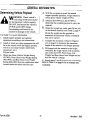
SAFETY
Safety
.Stop
the spreader before leaving the
vehicle to unclog, adjust, oil, or clean the
Definitions
spreader
.Before
servicing the spreader, wait for all
movement to stop.
.Keep
hands, feet, and clothing away from
power-driven parts and the conveyor chain.
.Do
not climb on or allow others to climb
on the spreader at any time while operating.
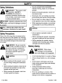
C
AUTION:
Indicates a situation that, if not
avoided, could result in damage to product
or property.
.While
operating the spreader, use auxiliary
warning lights except when prohibited by
law.
N
OTE: Identifies tips, helpful hints, and
maintenance information the reader should
know.
Safety
I CAUTION:
I
.Do not operate a spreader in need of
maintenance.
Precautions
Observe the following safety procedures before
and during the use of the spreader.By following
these rules and applying common sense,possible
injury and potential damage to the product may
be avoided.
.Before operating the spreader, reassemble
any parts or hardware that were removed.
.Before operating the spreader, remove
materials such as cleaning rags, brushes,
and hand tools from the spreader.
Battery
.A
Safety
void exposing battery to a spark or flame.
.Always
area.
charge battery in a well ventilated
.Before working with the spreader, secure
all loose fitting clothing and unrestrained
hair.
.A
.Before starting the spreader,check that all
personnel and equipment are clear of the
spreaderand the spray area-
.Always
disconnect battery before
removing or replacing any electrical
.Before operating the spreader,check that
all safety guards are in place.
.Never
lay anything on a battery .This
could result in electrical shock or bums, or
damage to the vehicle or equipment.
'm No, 80324
void contact with battery acid. It can
cause serious personal injury and damage
to the equipment.
components.
1
November
1, 1996
SAFETY
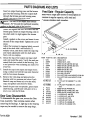
Spreader
Labels
The diagram below indicates the location of the
safety and identification labels. The numbers in
the diagram correspond to the numbers listed
below.
7~
53~
7
, 5
11
,
/~
3
9
0
FISHER@ Deca14-1/2
0
Serial
X 15
(PN 20724)
8
Number
Label
(No
p .N.)
0A
Form No.80324
2
November
1.1996
SAFETY
~
Form No.80324
3
November
1, 1996
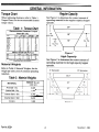
GENERAL
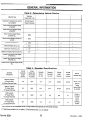
Torque
INFORMA TION
Chart
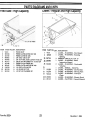
Regular Capacity
When tightening fasteners, refer to Table I,
See Figure 1 to determine the correct amount of
Torque Chart, for the recommended fastener
torque values.
spreading material for the regular capacity hopper
spreader .
Table
1: Torque Chart
Figure 1
High Capacity
See Figure 2 to detennine the correct amount of
spreading material for the high capacity hopper
Material
Weights
spreader.
Refer to Table 2, Material Weights, for the
weight per cubic yard of common spreading
materials.
Table 2: Material
MATERIAL
Weights
WEIGHT
cubic
(Ib. per
yd.)
Fine Salt -Dry
2.025
Coarse Sand -Wet
3,240
Cinders
1,080
Form No.80324
4
November
1, 1996
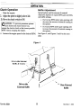
GENERAL
Determining
Vehicle
INFORMA TION
4. With the occupants in truck for nonnal
Payload
hopper spreader operation, weigh vehicle to
obtain gross vehicle weight (GVW).
5
Subtract the GVW from the GVWR to
detennine the available payload to carry the
material.
6. Obtain the weight per cubic yard (lb./cu. yd.)
of the desired material from Table 2, page 4.
Divide the weight into the payload to
detemline the maximum volume of material
that can be carried.
Use Table 3 to record information.
I. Install hopper spreaderand optional
equipment according to the instructions.
7. Compare the maximum volume to Figures I
or 2 on page 4 to determine the maximum
height of the material in the hopper spreader.
2. Install or attach any other equipment that will
be on the vehicle while the hopper spreader
will be in use (step bumper, trailer hitch,
8. Fill hopper with the material to the height
calculated. Re-weigh vehicle with occupants
and verify the GVW, Front Gross Axle
Weight, 'and Rear Gross Axle Weight are less
than the vehicle's ratings.
snowplows, etc.).
Fill gas tanks.
3. Obtain the Gross Vehicle Weight Rating
(GVWR), Front Gross Axle Weight Rating
(FGA WR), and Rear Gross Axle Weight
Rating (RGA WR) from the certification label
located inside the driver-side door jam.
Form No.80324
9. Repeat steps 7 and 8 for each type of material.
Refer to Table 3 on page 6 for an example and
worksheet.
5
November
1,1996
GENERAL
INFORMA TION
Table 3: Determining
Vehicle Payload
Example:
Coarse Salt -Dry
Material Type
Equipment installed when vehicle
RC Mild Steel 8'
was weighed
Hopper Spreader
Front Gross Axle Weight Rating
(FGAWR)
Rear Gross Axle Weight Rating
(RGAWR)
Gross Vehicle Weight Rating
8600
(GVWR) (lb.)
Gross Vehicle Weight (GVW) (lb.)
-6500
(empty)
=
Payload Available (lb.)
2100
Material Weight (lbJcu. yd.)
+ 1431
Maximum Volume (cu. yd.)
= 1.47
Maximum Height (Approximate)
~
(in.)
24"
Loaded Front Gross Axle Weight
(FGAW) (lb.)
Loaded Rear Gross Axle Weight
(RGAW) (lb.)
Loaded Gross Vehicle Weight (GVW)
(lb.)
Table 4: Spreader Specifications
Overall
Spreader
Description
Spreader
Empty
Weight
(lb.)
Length
(No screen
(inches)
or battery)
Capacity
Struck
Capacity
Rounded
Overall
Overall
Width
Height
(inches)
(cu. yd.)
(cu. yd.)
(inches)
1.8.
2.3*
50-3/4
Recommended
Use
Regular Capacity
8' Hopper Body
113
624
32-1/2
314 or 1 Ton
16 Gauge Stainless Steel
Pick-up
Regular Capacity
8' Hopper Body
above 8500
Trucks
113
820
1.8**
2.3**
50-3/4
32-1/2
Ib. GVWR
113
1000
2.6
3.2
58
41
Dump or
Flat Bed
12 Gauge Mild Steel
High Capacity
8' Hopper Body
12 Gauge Mild Steel
Trucks
above
High Capacity
10' Hopper Body
137
1200
3.3
4.1
12 Gauge Mild Steel
58
41
15,000 Ib
GVWR
, Side Extensions are not recommended for the 16 Gauge Stainless Steel Spreader and will void all warranties.
,* 6" Side Extension adds 0.6 cu. yd. capacity, 12" Side Extension adds 1.2 cu. yd. capacity.
Form No.80324
6
November
1,1996
OPERA TION
Cab Control
8 When the engine starts, release the ignition
Identification
switch.
N
OTE: If the engine does not start after 10
secondsof cranking, turn both vehicle and
spreader ignition switches to OFF and see the
Briggs & Stratton Owner's Manual that is
shipped with the spreader.
9. After the engine starts, move the throttle
switch to IDLE and hold for 1/2 -1 second to
release the choke.
10. To control the engine speed:
.Increase:
hold the throttle switch at
CHOKFlFAST .
Figure 3
.Decrease:
N
N OTE: The conveyor and spinner will
operate when the clutch switch is in the ON
or BLAST position.
hold the throttle switch at IDLE.
OTE: Maximum engine speed is obtained
just prior to choking the engine.
Stopping
the Engine
1. Move the throttle to illLE
Engine
Operation
and hold for two
seconds.
Refer to Figure 3 as a reference for starting and
stopping the engine.
2. Turn the spreader ignition switch to OFF.
Starting the Engine
N
OTE: Read and understand the engine
manufacturer's Owner's Manual before
starting the engine.
Turn the vehicle ignition switch to ON.
2. Verify the clutch switch is OFF.
Turn the spreaderignition switch (labeled
"Engine" on the cab control) to ON.
4. Move the throttle switch to IDLE and hold
for two seconds; release.
5. Turn the spreaderignition switch to START .
While the engine is cranking, move the
throttle switch to CHOKE/FAST .
When the engine starts to fire, release the
throttle switch.
Form No.80324
7
November1,1996
~
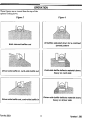
OPERA TION
Clutch
.Start
Operation
Baffle Adjustment
the engine.
Spread pattern and the amount of material
dispensed depends on engine RPM, gate position,
and baffle settings.
2. Adjust the speed to slightly above idle.
3. Move the clutch switch to ON.
.Decreasing RPM and/or gate-opening will
decrease the amount of material coming to
the spinner.
.Increasing RPM and/or gate-opening will
increase the amount of material coming to
the spinner.
See Figure 4, and Figures 5 and 6 on the next
4. Increase the engine speed to the desired RPM.
page.
Figure
4
Driver-side Internal
Baffie & Control \
\
.\
/
/
/
/
,,,
Driver-side
External Bame
Form No.80324
8
,
Rear External
Dame
November
1, 1996
OPERA TION
These figures are as viewed from the top of the
spinner looking down.
Figure 5
Form No.80324
Figure
9
6
November
1, 1996
MAINTENANCE
.Maintain
spinner shaft-to-gear case roller
chain tension. Correct chain tension allows
5/16" deflection midway between the
sprockets. See Figure 7.
To increase chain tension: loosen the
bearing mounting hardware and pull the
spinner shaft away from the gear case.
Make sure the spinner shaft is vertical and
the sprockets are lined up before
re-tightening the fasteners. Oil this chain
after each use, and at the end of the season.
General
At the end of the season,oil or paint all
bare surfaces after washing and before
storing the unit.
Grease
.Use dielectric greaseon all electrical
connections at the beginning and end of
each season,and as required during the
season.
.After
every lO hours of operation, grease
the idler bearings on the idler shaft,
flanged bearings on the drive shaft and the
input shaft above the gear case, and the
spinner shaft bearings.
.After
every 50 hours of operation, grease
the input shaft bearing on the gear case and
verify the oil level of the gear case is level
with the fill hole.
Figure
7
.Maintain
engine-to-electric clutch roller
chain tension. Correct tension allows 5/16"
deflection midway between sprockets. See
Figure 8.
.Change gear case oil once a year. Drain oil
by removing the side cover of the gear
case. Refill with SAE 90 weight gear oil.
Oil level should be even with the fill hole.
Chains
At the beginning of each season,and once
a month during the season,verify the drive
sprocket set screws are tight.
Figure 8
To increase chain tension: loosen the four
engine mount-to-engine base bolts and pull
the engine away from the electric clutch.
Re-tighten bolts. Oil this chain after each
use, and at the end of the season.
Form No.80324
10
November
1 , 1996
MAINTENANCE
Periodically check the conveyor chain
tension.
To check the tension, measure in 201'-24"
from the rear edge of the sills. Push up on
the chain with your hand. The conveyor
chain should lift 1"-3" off the conveyor
chain guide or cross angles. See Figure 9.
Electric
Clutch
To minimize problems and extend the life of the
electric clutch, do the following:
.At
the end of each snow season,remove
and clean the clutch.
.After
cleaning the clutch, coat both
mating surfaces of the clutch with oil or
light grease.
.Remove oil and greaseprior to using the
clutch again.
Engine
Service
and
Repair
Maintain the spreader engine according to the
Briggs & Stratton Engine Owner's Manual that
is shipped with the spreader. Engine warranty is
covered by Briggs & Stratton and is described in
the back of the manual.
If service or repair is needed, contact an
authorized Briggs & Stratton Service Center. To
serve you promptly, the Service Center will need
the model, type, and code number for your
Figure 9
engine.
Your nearest service center is listed in the
"Yellow Pages" under "Engines, Gasoline" or
"Gasoline Engines."
.Use
the (2) 5/8" x 6" take-up bolts at the
front of the spreader to adjust the conveyor
chain tension. Turn both sides equal
amounts to ensure the tension is equally
distributed across both sides of the
conveyor chain.
.Always
empty the spreader when it is not
in use to prevent a frozen conveyor chain.
ABBREVIA
AR
ASSY
CB
CHMSL
CNP
CS
DIA
ELEC
EX
FL
G
HC
HP
HSG
As Required
Assembly
Carriage Bolt
Center High-Mounted Stoplight
Cone Point
Cap Screw
Diameter
Electric
External
Flat
Grade
High Capacity
Horsepower
Housing
Form No.80324
HX
ID
LO
LK
MS
MS
NP1F
NYIS
PH
PN
PT
RC
SAE
SBH
TION KEY
Hex (Head)
Inside Diameter
Long
Lock
Machine Screw (fastener descriptions)
Mild Steel (non-fastener descriptions)
National Pipe Thread (Fluid)
Nylon Insert
Cross Recessed (Phillips Head)
Pan
Prevailing Torque
Regular Capacity
Society of Automotive Engineers
Socket Button Head
11
SOTS
SFLS
SO
SP
SQ
SS
STD
STS
T
1FTS
TV
zYC
ZP
Self-Drilling Tap Screw
Serrated Flange Lock Screw
Socket Head
Spring
Square
Set Screw
Standard
Stainless Steel
Tooth/Teeth
Thread Forming Tapping Screw
Type
Zinc Yellow Chromate
Zinc Plated
November
1. 1996
PARTS
DIAGRAMS
Items with a single part
number or description are
11
~
AND LISTS
' .0 0..",
"' 25
common to regular capacity
mild steel and 16-gauge stainless steel
14-
24 "
14" and 26" chute assemblies.
23,
.0
-8
0-/
10
17, 18 (2 REa), 19, 20
""',
2
6--4
,3
~
/~-
17, 18 (2 REO), 19, 20
,
,/
6/
5
,
I
9
/
5
/
/
12
/
~
/13
/
/
ITEM
PARTNO.
1
1
1
9189
9031
9194
1
2
2
9032
.9298
.20092
2
.9299
2
3
4
.20093
..9195
..9201
5
..91004
6
7
..9261
..20599
8
8
9
9
10
.9191
.9192
.9196
.20095
.9193
.9187
.91022
.9265
.9197
12
13
14
Form No.80324
QTY. DESCRIYnON
ITEM
PARTNO.
1
1
1
1
1
1
CHUTEASSY
141'RCMS
CHUTE ASSY 14'1 RC STS
CHUTEASSY26"RCMS
CHUTE ASSY 26'1 RC STS
CHUTEHSGASSY
14"RCMS
CHUTE HSG ASSY 14" RC STS
17
17
18
18
19
19
.90111
.91014
.90315
.91006
.90361
.91007
1
1
CHUTE HSG ASSY 26" RC MS
CHUTE HSG ASSY 26" RC STS
20
20
.90334
.91008
3
2
CONTROL ROD 10"
ADJUSTMENT
PIN
21
21
90315
91006
3
5
1
1/8X3/4 COTTER PIN ZP
3/32X2-1/4HAIRPIN
COTTER
LABEL -INFORMATION
22
22
23
90361
91007
90334
1
(WARNING)
SPINNER SHAFr
RC ZYC (14" CHT)
23
24
91008
90103
1
1
1
SPINNER SHAFr RC ZYC (26" CHT)
SPINNERDISKRCMS
SPINNER DISK RC STS
24
25
*
91015
9188
.20353
2
3/4" PILLOW
1
SPROCKET,
1
1
1
1/16X1/2 COTTER PIN
1/4 X 1-1/2 CLEVIS SHEAR PIN
MACHINE KEY, 3/16" SQ X 1" LG
BLOCK
ZP
QTY. DESCRIP'nON
4
4
8
8
4
4
4
3/8-16X1-1/2 HX CS
3/8-16X1-1/2 HX CS
3/8 PLAIN WASHER
3/8 PLAIN WASHER
3/8 SP LK WASHER
3/8 SP LK WASHER
3/8-16 HX NUT ZP
4
4
4
4
4
4
4
3/8-16HXNUTSTS
3/8 PLAIN W ASHER
3/8 PLAIN WASHER
3/8 SP LK WASHER
3/8 SP LK WASHER
3/8-16 HX NUT ZP
3/8-16 HX NUT STS
4
4
3/8-16X1
3/8-16X1
1
#40 ROLLER
CHAIN,
1
#40 ROLLER
CHAIN
G5 ZP
STS
TY A STD ZP
TY A STD STS
ZP
STS
TY A STD ZP
TY A STD STS
ZP
STS
HX CS G5 ZP
HX CS STS
38" LONG
MASTER
LINK
BEARING
#40X24TX3/4"
ID
12
November
1. 1996
~
PARTS
Chute Assembly
-High
DIAGRAMS
AND LISTS
Capacity
11
-
,
~~~
25
22
23,
24
"
"""'
,"
O /8
14
26
10
/ r--.
"
"
,
17, 18 (2 REa),
0
--?
20
-21
.~
~
18,
./
19,
-2
20
7
6
6-
19,
b+--3
17, 18 (2 REQ), 19, 20
65
.9
/1
LJ
/
/
5
12
13
/
/
,j/
ITEM
PART NO.
1
2
9107
.20318
3
4
..9195
..9201
5
6
7
..91004
..9261
..20599
ITEM
QTY. DESCRIPI10N
1 CHUTE ASSY 31 " HC MS
1 CHUTE HSG ASSY 31 " HC MS
3
2
3
CONTROL ROD 10"
ADJUSTMENT
PIN
1/8 X 3/4 COTTER PIN ZP
S
3/32X2-1/4HAIRPIN
1
LABEL -INFORMATION
(W ARNIN G )
COTTER
ZP
8
20320
1
SPINNER
9
20321
10
20322
11
20323
1
2
1
(31" CHT)
SPINNER DISK HC MS
1" PILLOW BLOCK BEARING
SPROCKET, #40 X 24T X 1" ID
12
91022
20351
1
1/16X1/2 COTTER
13
14
20324
1
1
1/4" X 2" CLEVIS PIN ZP
MACHINE
KEY 1/4" SQ X 1" LG
17
90111
90315
4
3/8-16/1-1/2
18
19
90361
Form No.80324
10
6
SHAFf
PART NO.
QTY. DESCRIFI10N
20
21
22
23
.90334
.20326
90315
90361
6
1
4
3/8-16HXNUTZP
ACCESSPANEL
3/8 PLAIN W ASHER TY A STD ZP
4
3/8 SP LK WASHER
24
90334
25
26
*
90103
20325
.20353
4
4
3/8-16HXNUTZP
3/8-16Xl HX CS G5 ZP
1
#40 ROLLER
CHAIN,
1
#40 ROLLER
CHAIN
ZP
42" LONG
MAS1ER
LINK
HC ZYC
*Not Shown
Abbreviation Key found on page 11.
Indented parts are included in the assembly under which
they are listed.
Quantities shown are included with the assembly.
PIN ZP
HX CS GS ZP
3/8 PLAIN WASHER TY A STD ZP
3/8 SP LK W ASHER ZP
13
November
1, 1996
PARTS DIAGRAMS
Conveyor
Drive and Idler -Regular
AND LISTS
Capacity
N
'm
No.80324
14
OTE: Assemble chain link and pin to
chain bar as shown.
November
1. 1996
PARTS DIAGRAMS
Conveyor
Drive and Idler -Regular
AND LISTS
Capacity
Items with a single part number or description are common
to regular capacity, mild steel and 16-gauge stainless steel
spreaders.
ITEM PARTNO. QTY. DESCRIPTION
I
I
4
5
6
10
11
12
13
14
16
17
18
20085
20094
9171
9169
9167
9172
9184
9164
9182
9183
9163
9174
9177
19
20
21
22
23
24
25
26
27
27
28
28
29
.9181
.9178
.9179
.91010
9447
91011
9162
9176
90461
91012
90054
90977
90311
AR
AR
AR
AR
2
2
2
1
5
5
2
2
5
29
91013
5
30
31
67093
90103
91015
4
4
4
31
ITEM
1 ENGINE BASE RC MS
I ENGINE BASE RC STS
1 GEAR CASE
1 DRIVE SHAFf COUPLING
1 WIPER BELT RC
2 STRAP, RUBBER HOLD DOWN
1 illLER SHAFf RC ZYC
I DRIVE SHAFf RC ZYC
2 ROD END RC
2 illLER SPROCKET 6T
2 DRIVE SPROCKET 6T
1 SPROCKET#40XI6TX1.0"
ill
I CONVEYOR CHAIN 8' RC
PART NO.
QTY. DESCRIYnON
32
32
90608
91016
4
4
1/2-13X1
1/2-13X1
33
33
35
20150
20151
90980
2
5/8-11X6"TAKE
2
2
5/8-11X6'1 TAKE UP BOLT STS
5/16 PLAIN WASHER TY A STD
36
36
37
38
90359
91017
90981
90361
5
5
1/4 SP LK WASHER
1/4 SP LK WASHER
ZP
STS
38
39
39
40
91007
90364
91018
90315
40
42
42
43
91006
90330
91019
90332
2
8
8
4
4
4
4
5/16 SP LK W ASHER
3/8 SP LK W ASHER
3/8 SP LK W ASHER
1/2 SP LK W ASHER
1/2 SP LK WASHER
3/8 PLAIN WASHER
3/8 PLAIN WASHER
STS
ZP
STS
ZYC
STS
TY A STD ZP
TY A STD STS
43
44
44
45
45
47
48
49
50
51
52
*
90988
90334
91008
90343
91020
91021
91022
20189
67147
9166
20188
9333
5
5
2
2
8
8
2
2
2
2
2
2
1/4-20 HX NUT ZP
1/4-20 HX NUT STS
5/16-18 HX NUT ZP
5/16-18 HX NUT STS
3/8-16HXNUTZP
3/8-16 HX NUT STS
5/8-11 HX NUT ZYC
5/8-11 HX NUT STS
1/8X1 COTTER PIN
1/16X1/2 COTTER PIN ZP
3/16X1-1/4!1 ZYC CLEVIS PIN
3/8X2 CLEVIS PIN G5 ZYC
*
9334
3
2
4
4
MACHINEKEY,1/4!1SQX1-1/2LG
GREASE FITTING -STRAIGHT
TIE-DOWN
CHAIN 36!1 LONG
LINK -CHAIN
TIE DOWN
4
4
#10-24 X 1/2 SBH CS STS
#10-24 PT HX LKNUT NYIS STS
HX CS G5 ZP
HX CS STS
UP BOLTZYC
STS
(12"-123 LINK)
CONVEYOR CHAIN BAR RC
CONVEYOR CHAIN LINK
CONVEYOR CHAIN PIN
3/32Xl/2 COTTER PIN ZP
1/4-20 x 1/2 SO SS CNP
5/16-18X3/4 SQ SS STS
1-1/8" 2 BOLT FLANGE BEARING
1" 2 BOL T FLANGE BEARING
1/4-20X3/4 HX CS G2 ZP
1/4-20X3/4 HX CS STS
5/16-18Xl-l/2 HX CS G5 ZP
5/16-18X1-1/2 HX CS STS
1/4 PLAIN WASHER TY A STD
ZP
1/4 PLAIN WASHER TY A STD
STS
3/8-16X1-1/4 SBH CS STS
3/8-16Xl HX CS G5 ZP
3/8-16X1 HX CS STS
53
67092
54
91330
* Not Shown
Abbreviation Key is found on page 11.
Indented parts are included in the assembly under which
they are listed. Quantities shown are included with the assembly.
Form No.80324
15
November
1, 1996
PARTS DIAGRAMS
Conveyor
Form No.80324
Drive and Idler -High
AND LISTS
Capacity
16
November
1, 1996
PARTS
ITEM
I
4
PART NO.
20327
9171
5
9169
6
20328
10
9172
II
20329
12
20330
13
20331
14
20332
16
20333
17
9174
18
20334
18
20335
1
1
1
ENGINE BASE HC MS
GEAR CASE
DRIVE SHAFr COUPLING
1
2
1
WIPER BELT HC
STRAP, RUBBER HOLD
illLER SHAFr HC ZYC
1
2
2
2
1
1
DRIVE SHAFr HC ZYC
ROD END HC
illLER SPROCKET 8T
DRIVE SPROCKET 8T
SPROCKET, #40 X 16TX 1.0" ill
CONVEYOR
CHAIN 8' HC
1
(16"-123 LINK)
CONVEYOR
CHAIN
.20336
.9178
.9179
.91010
9447
91011
20337
9176
90461
90054
90311
AR
AR
AR
AR
2
2
2
1
7
2
7
30
31
67093
90103
8
4
AND LISTS
ITEM
QTY. DESCRIPTION
19
20
21
22
23
24
25
26
27
28
29
Form No.80324
DIAGRAMS
DOWN
10' HC
QTY. DESCRIPTION
90608
4
1/2-13X1 HX CS G5 ZP
33
35
20338
90980
2
5/8-11 X 9"TAKE
2
5/16 PLAIN
36
90359
90981
90361
90364
90315
7
STS
1/4 SP LK WASHER
37
38
39
40
42
43
44
45
47
48
(16"-153 LINK)
CONVEYOR
CHAIN BAR HC
CONVEYOR
CHAIN LINK
CONVEYOR
CHAIN PIN
3/32X 1/2 COTTER PIN ZP
1/4-20 X 1/2 SO SS CNP
5/16-18X3/4 SQ SS STS
1-1/8"4 BOLT FLANGE BEARING
1" 2 BOL T FLANGE BEARING
1/4-20X3/4HX
CS G2 ZP
5/16-18Xl-1/2
HX CS G5 ZP
1/4 PLAIN WASHER TY A STD
PART NO.
32
49
50
51
52
*
*
53
54
90330
90332
90334
90343
91021
91022
20189
67147
9166
20188
9333
9334
67092
91330
2
12
4
4
7
2
12
2
2
2
2
2
3
2
4
4
4
4
UPBOLTZYC
WASHER
TY A STD
ZP
5/16 SP LK WASHER STS
3/8 SP LK WASHER ZP
1/2 SP LK W ASHER ZYC
3/8 PLAIN WASHER TY A STD ZP
1/4-20 HX NUT ZP
5/16-18HXNUTZP
3/8-16HXNUTZP
5/8-11 HX NUT ZYC
1/8X1 COTrER PIN
1/16X1/2 COTrER PIN ZP
3/16X1-1/4 ZYC CLEVIS PIN
3/8X2 CLEVIS PIN G5 ZYC
MACHINEKEY,1/4"SQX1-1/2LG
GREASE FITnNG
-STRAIGHT
TIE-DOWN
CHAIN 36" LONG
LINK -CHAIN
TIE DOWN
#10-24 X 1/2 SBH CS STS
#10-24PTHXLKNUTNYIS
STS
* Not Shown
Abbreviation Key is found on page 11.
Indented parts are included in the assembly under which
they are listed. Quantities shown are included with the as-
ZP
3/8-16Xl-1/4
SBH CS STS
3/8-16X1 HX CS G5 ZP
sembly.
17
November
1,1996
PARTS DIAGRAMS
Form No.80324
18
AND LISTS
November
1, 1996
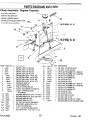
PARTS
DIAGRAMS
Engine Drive with Clutch -Regular
ITEM
PART NO.
LK WASHER
ZP
3
1/4 EX TOOTH
LK WASHER
STS
30
30
90359
91017
3
3
1/4 SP LK WASHER
1/4 SP LK WASHER
BATTERY CASE W/STRAP
ELECTRIC CLUTCH
TUBULAREXHAUST
EXTENSION
31
32
32
33
90360
90361
91007
90980
7
4
4
10
I
I
2
I
RELAY-HOPPERSPREADER
RUBBER GROMMET,
I"
LOCKING
COLLAR,
I"
SPROCKET, #40 X 12TX
34
35
35
90987
90330
91019
I
I
SPROCKET, CLUTCH (#40 X 52 T)
AL TERNA TOR WIRE WITH
PLUG
36
36
37
90332
90988
90334
9220
20341
67239
I
I
I
37
38
91008
90315
91006
sm STS
5/16-18 PT HX LK NUT NYIS STS
1/4-20 HX NUT ZP
1/4-20 HX NUT STS
5/16-18HXNUTZP
5/16-18 HX NUT STS
3/8-16 HX NUT ZP
3/8-16 HX NUT STS
3/8 PLAIN WASHER TY A sm ZP
3/8 PLAIN WASHER TY A sm
9227
9226
67241
9281
20097
20342
90461
91012
90974
I
I
I
I
I
I
7
7
8
#40 ROLLER CHAIN, 39" LONG
#40 ROLLER CHAIN, 47" LONG
BATTERY CABLE -38
BLACK 53"LG
CABLE-STARTER
RED BATTERY CABLE (POS)
CLUTCH GROUND WIRE
ENGINE COVER RC MS
ENGINE COVER RC STS
ENGINE COVER HC MS
1/4-20X3/4 HX CS G2 ZP
1/4-20X3/4 HX CS STS
5/16-18X3/4HX
CS STS
5
7
7
4
4
4
4
4
4
42
43
44
*
9166
67092
91330
20353
2
4
4
I
STS
KEY, .25 SQ X 1-1/2"LG
#10-24XI/2
SBH CS STS
#10-24 PT HX LKNUT NYIS STS
#40 ROLLER CHAIN MASTER LINK
90054
90965
4
5/16-18XI-I/2
4
3/8-16XI
9207
9000
17
18
19
21
21
21
22
22
23
24
26
QTY. DESCRIPTION
1/4 EX TOOTH
5
6
16
PART NO.
3
9208
20096
20340
9229
15
ITEM
91031
67083
3
3
3
*
15
QTY. DESCRIPTION
3/8-16Xl CB STS
#8-18X3/8 SFLS 1FrS
9106
20084
20339
13
14
and High Capacity
4
4
1
2
2
7
8
9
II
AND LISTS
20136
9221
9206
9209
9202
20194
Form No.80324
I
8.5 H.P. ENGINE
I
ENGINE
26
91023
28
91160
I
I
ENGINE MOUNT HC
CHAIN GUARD RC MS
29
29
I
I
CHAIN
CHAIN
I
I
I
MOUNT
GUARD
GUARD
RC
RC STS
HC MS
1.0'1
(RC)
(HC)
TY AB ZP
ZP
STS
5/16SPLKWASHERSTS
3/8 SP LK WASHER ZP
3/8 SP LK WASHER STS
5/16PLAINWASHERTYA
* Not Shown
Items with a single part number or description are common
to regular capacity (mild steel and 16-gauge stainless steel)
and high capacity spreaders.
HX CS G5 ZP
CB G5 ZP
19
November
1,1996
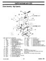
PARTS DIAGRAMS
AND LISTS
Gear Case
Form No.80324
20
November
1, 1996
PARTS DIAGRAMS
Gear
Case
ITEM
PART NO.
QTY. DESCRIPTION
AND LISTS
ITEM
PART NO.
1
9171
1
GEAR CASE
17
.67258
AR
2
.67245
.67259
.67246
.67247
GEAR CASE HOUSING
GEAR (BRONZE)
WORM GEAR
18
3
4
1
1
1
19
.67260
I
I
SNAP RING
WOODRUFF
5
6
7
.67265
.67266
.67249
1
1
INPUTS HAFf
OUTPUT SHAFf
20
.67261
I
(# 18 -HARDENED)
WOODRUFF
KEY
21
22
.67262
.67263
.67264
.7621
("A" -HARDENED)
1/8 VENT PLUG
.67248
.67250
.67251
BEARING
BEARING
BEARING
SEAL
I
8
9
10
2
2
4
1
I
I
I
ZERK FITnNG
SET SCREW
PLUG 3/8 NPTF SQ
11
12
13
.67252
.67253
.67254
1
1
2
CAP
SEAL
SNAP RING
14
15
16
.67255
.67256
.67257
1
4
1
COVER
CAPSCREW
GASKET
CONE
CONE
CUP
23
24
QTY. DESCRIPTION
SHIM
(0.020" 1HK)
KEY
* Not Shown
Abbreviation Key is found on page II.
Indented parts are included in the assembly under which
they are listed. Quantities shown are included with the
assembly.
Gear Case Assembly
Input
I.
Housing Pre-assembly
1. Insert the snap ring into the output bore of the
Shaft
Pre-assembly
Install the snap ring in the snap ring groove.
2. Install the woodruff key into the keyway.
housing.
2. Insert an output bearing cup into the housing
bore using a cup driver or a brass drift. Press
the cup tight against the snap ring.
3. Slide the wonn gear on tight to the snap ring
making sure the key does not fallout.
4. Slide the input shaft bearing cones tight
against the wonn gear and snap ring.
3. Insert the snap ring into the input bore
opposite the grease zerk hole. Press an input
bearing cup tight against the snap ring.
Assembly
of Pre-assembled
Parts
1. Insert the input shaft into the housing making
sure the shaft extends out the proper side.
4. Install and tighten the greasezerk into the
2. Press an input bearing cup and a snap ring
into the input bore of the housing.
housing.
Cover Pre-assembly
2. Press an output bearing cup in tight against
the snap ring.
3. Adjust the bearings by tapping lightly on each
end of the shaft with a soft hammer. If
endplay exists, add shims under the snap ring
and repeat adjustment until the shaft spins
freely with no endplay.
3. Install all vent and fill plugs into the cover.
Continuedon nextpage.
1. Insert the snap ring into the output bore of the
cover.
Output
Install
Shaft
Pre-assembly
the woodruff
Form No.80324
key into the keyway
21
November
1, 1996
PARTS DIAGRAMS
Insert an output bearing cone and the bronze
gear into the housing. Slide the output shaft
through the bronze gear and bearing cone,
taking care not to scratch the shaft.
AND LISTS
Items with a single part number or description are
common to regular capacity, mild steel and
16-gauge stainless steel spreaders.
N
OTE: The end of the output shaft should
extend 1.9411
beyond the machined mounting
surface on the back side of the housing.
Install and tighten the D43 set screw into the
bronze gear.Insert an output bearing cone on
the shaft until it is tight against the bronze
gear.
Install a gasket on the cover and insert it over
the end of the output shaft. Tighten the cover
down.
Adjust the bearings by tapping lightly on each
end of the shaft with a soft hammer. If
endplay exists, add shims under the snap ring
and repeat adjustment until the shaft spins
freely with no endplay.
6. Grease the lips of the output and input shaft
seals and install the seals.Verify the sealsare
seatedflush (not cocked) in the housing. Use
a seal protector when installing any sealsover
a keyway.
ITEM
7. Install the caps in the input and output bores
using a sealant on both the cap outer diameter
and the bore inner diameter.
8. Remove the vent plug and pressurize the
housing with low pressure air (about 3 psi).
Brush a soap and water mix over the seals,
caps, and gaskets and check for leaks.
Gear Case Disassembly
To disassemble the gear case,reverse the Gear
Case Assembly. Take extreme caution when
removing the bearings. A light tap on the bearing
cups may be needed to remove the snap rings.
Form No.80324
9231
20098
9232
20099
9233
20100
90965
4
5
5
6
6
9. Install the gear case on spreader,greaseinput
shaft bearing, and fill unit with gear oil to a
level even with the fill hole.
22
PART NO.
I
I
2
2
3
3
4
QTY. DESCRIPnON
1
WING
91023
90986
90999
1
1
1
1
1
1
1
1
1
WING NUT -STS
FEEDGATE~EVERRCMS
FEED GA TE LEVER RC STS
FEED GA TE RC MS
FEED GATE RC STS
3/8-16X1 CB G5 ZP
3/8-16X1 CB STS
3/8-16 PT HX JAM LKNUT NYIS ZP
3/8-16 PT HX JAM LKNUT NYIS
90315
2
STS
3/8 PLAIN
WASHER
TY A STD
2
ZP
3/8 PLAIN
W ASHER
TY A STD
STS
FEED GA TE WIPER RC
FEED GA TE ANGLE RC MS
FEED GA TE ANGLE RC STS
1/4-20X3/4 FL MS ZP
91006
8
20102
9
91030
1
1
1
4
7
9234
8
9235
NUT
9
91025
4
1/4-20X3/4
10
90330
10
91019
4
4
1/4-20 HX NUT ZP
1/4-20 HX NUT STS
FL MS STS
11
90359
11
91017
4
4
1/4 SP LK WASHER
1/4 SP LK W ASHER
ZP
STS
November
1, 1996
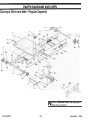
PARTS
Feed Gate -High
ITEM
PART NO.
DIAGRAMS
AND LISTS
Capacity
QTY. DESCRIP'nON
ITEM
PART NO.
QTY. DESCRIPTION
1
9231
I
WING NUT
1
9131
1
LABEL
-W ARNING
-Fire
2
20344
I
I
I
I
2
I
I
6
6
6
FEED GATE LEVER HC MS
FEED GATE HC MS
3/8-16XI CB G5 ZP
3/8-16 PT HX JAM LKNUT NYIS ZP
3/8 PLAIN W ASHER TY A sm ZP
FEED GATE WIPER HC
FEED GATE ANGLE HC MS
1/4-20X3/4FL
MS ZP
1/4-20 HX NUTZP
1/4 SP LK WASHER ZP
2
20599
1
LABEL
-W ARNING
-Rotating
3
4
20724
20598
3
1
Spinner
FISHER@ DECAL 4-1/2 X 15
LABEL -W ARNING -Read
5
9133
2
Instruction Manual
LABEL -W ARNING
3
20345
4
90965
5
90986
6
90315
7
20346
8
20347
9
91030
10
90330
11
90359
Form No.80324
23
1
9414
2
1
2
LABEL
LABEL
LABEL
20600
20143
1
1
Chain
LABEL -W ARNING -Electric Shock
LABEL -CAU11ON
-Unused Material
6
9129
8
9134
9
II
-Overloaded
Vehicles
LABEL -SERIAL
7
10
Hazard
-Serial
-W ARNING
-W ARNING
-W ARNING
No.
-Do Not Ride
-Moving Parts
-Conveyor
November
1, 1996
PARTS DIAGRAMS
AND LISTS
Cab Control
Front View
2
0
D
Electric Throttle
2/
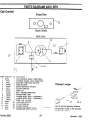
ITEM PARTNO
1
2
3
4
5
6
7
*
20354
.9427
.9422
.67026
.20162
.9237
.67027
.65368
8
9
10
11
12
13
14
*
*
.20088
.20089
.20090
.20086
90681
9472
9415
3042
8329
Form No.80324
QTY. DESCRIPrION
1
1
1
I
I
1
1
1
1
I
I
I
AR
AR
AR
AR
I
CAB CONfROL (ELEC. THRO1TLE)
CONfROL PANEL -ELEC THRO1TLE
ELECTRIC THRO1TLE SWITCH
FUSE HOLDER
KEYED IGNITION SWITCH
CLUTCH SWITCH
FUSE CAP
KEY -HOPPER SPREADER
POWER WIRE -RED
JUMPER WIRE -RED -4 TERMINAL
JUMPER WIRE -RED -3 TERMINAL
FUSE 3 AG -10 AMP
1/4X3/4 HX SDTS ZP
CLAMP LOOP #10
CLAMP LOOP #6
RUBBER GROMMET 3/8" ID.
DIELECTRIC GREASE TUBE
24
Clamp
Loops
"
\jiP
"
12
""
13, 14
U sed to secure spreader harness
Not shown
and spreader cable to the spreader
and the cab control.
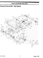
November
1, 1996
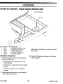
PARTS
Vehicle
Part
DIAGRAMS
AND LISTS
Harness
Number:
20072
Brown -Electric
,
l
GREEN
RED
BROWN
BLACK
ORANGE
WHITE
Orange -CHMSL
,
-Vehicle
~
Ground
~
Green -Electric
Throttle Switch
,
~
/
Green -Electric
Throttle Switch
Spreader
Part
Number:
Gray -Electric
Switch
~Clutch
Green
GRAY
Throttle
Red -Electric
Throttle Switch
White -Starter
Relay Ignition
Switch
~
Black- Magneto
\
Ignition Switch
Green -Ground
Ignition Switch
Harness
Black -
20073
White -Magneto
RED
BROWN
ORANGE
/;;:::r--
Starter Relay
Gray -I
Electric ~
Clutch
Red
GreenGround
\
~
D
-
Green
Electric
~
Throttle
Brown Electric
Throttle
Plug
Cover
Part Number:
Form No.80324
\Orange -
-
CHMSL
Ground
CHMSL
Hook
8291
Part Number:
25
20128
November
1. 1996
PARTS
CI~,..tri,..
Electric
Thrnttl~
Throttle
Throttle
DIAGRAMS
AND
3--~
Pin~3
LISTS
Crank (shown
against the
Electric
Throttle
Bracket
~
~,
according to step 4 of the
...
installatIon
2
InstructIons
below.)
Engine Mount
9
ITEM
PARTNO
>
ITEM
QTY. DESCRIPTION
I
2
20163
20134
I
I
ELECfRIC
ELECfRIC
THROT11.E
THROT11.E
BRACKET
MOTOR
3
4
5
20129
67091
91027
I
3
3
ELECfRIC
THROT11.E ARM
#6-32X5/8 SBH CS STS
#6-32 PT HX LK NUT NYIS STS
Disconnect
the battery
cables.
90359
1/4-20X3/4 HX CS 05 ZP
1/4 PLAIN WASHER TY A STD ZP
1/4 SP LK W ASHER ZP
20359
I
NUT BAR
7
90311
8
9
4. U sing the electric throttle control, run the new
electric throttle motor until the crank is
against the bracket as shown in above
2. Carefully observe the existing installation.
Mark the electric throttle bracket position on
the engine mount.
diagram.
5. Place the electric throttle arm on the crank as
shown in the above diagram.
3. Disconnect the brown and red spreader
harnesswires from the electric throttle motor
leads.
6. Place the electric throttle assembly onto the
engine mount inserting the throttle pin into
the engine choke/throttle linkage plastic slider
(not shown).
7. Loosely bolt electric throttle assembly to the
engine mount with the existing hardware.
4. Remove 1/4-20 fasteners that hold the electric
throttle bracket to the engine mount.
5. Remove #6-32 fasteners holding the electric
throttle motor to the bracket. Remove the
electric throttle motor.
Installation
QTY. DESCRIPTION
2
2
2
90461
3. Fasten the electric throttle motor to the
bracket using the existing hardware.
Removallnstructions
1.
PARTNO
6
Instructions
8. Keeping the electric throttle arm parallel to
and against the carburetor control bracket,
move the electric throttle bracket forward
putting the engine throttle into the full choke
position.
9. Tighten the fasteners according to the Torque
Chart on page 4.
1. Connect the brown and red spreader harness
wires (not shown) to the corresponding
colored electric throttle motor leads.
10. Reconnect the battery cables.
2. Using the electric throttle control, run the new
motor until the crank reaches the 12 o ' clock
1
Verify the crank is stopped in both directions
by the bracket, not the carburetor linkage.
position. (A 9-volt battery can be a substitute
for the control. )
Form No.80324
26
November
1, 1996
A CCESSORI
Center
High-Mounted
Stoplight
ES
(CHMSL)
Kit
1
ITEM
PARTNO.
QTY. DESCRIP110N
KIT
ASSEMBL
rrEM
10
I.
9486
9487
I
I
STOPLAMP
STOPLIGHT
2
*
*
*
..9488
.9489
.9493
..9490
I
I
I
I
GASKET
STOPLIGHT GASKET
VEmCLE HARNESS-STOPLIGHT
PARTS BAG ASSY
PROTEcrOR
PLUG
5
6
*
*
*
*
*
Y W/
PART NO.
..90693
..90694
..5793
..8329
.3666
.6456
.13658
QTY. DESCRIPTION
2
2
1
1
10
1
1
#6-32 X3/4 PH PN MS STS
#6-32 PT HX LK NlJf NYIS STS
BUTT SPLICE
DIELECTRIC
GREASE TUBE
CABLE TIE
9-1-93 LITERATURE
CHMSL
CHMSL INST ALLA TION
SAE2CONTAcr
Installation
Instructions
Use the CHMSL manual supplied with the kit
for installation except for the following
situations:
.The CHMSL harnessand the protective
plug (supplied with the CHMSL kit) are
NOT used. The CHMSL plugs into the
SAE two-pin connector included as part of
the spreaderharness.
Indented parts are included in the
assembly under which they are listed.
Quantities shown are included with
the assembly.
* Not shown
.The orange CHMSL feedwire from the cab
control is connected to the vehicle
CHMSL signal. See Cab Control and Wire
Harness Installation.
Form No.80324
27
November
1,1996
ACCESSORIES
Inverted Vee Assembly
-Regular
Capacity Mild Steel
EndPlate
15,16,17
2
15, 16, 17
/
'<
G
""" Cross Channel
1
ITEM
20
PART NO.
9138
1
.20164
2
.20165
3
.65994
Installation
QTY .DESCRIPTION
1
1
1
1
INVERTED
INVERTED
INVERTED
INVERTED
ITEM
VEE
VEE
VEE
VEE
KIT RC MS
PLATE
SUPPORT
RC MS
15
16
17
PART NO.
.90103
.90361
.90334
QTY. DESCRIPflON
10
10
10
3/8-16Xl HX CS 05 ZF
3/8 SF LK WASHER ZP
3/8-16HXNUTZP
Indentedpartsare includedin the assemblyunderwhich they are listed.
Instructions
4. Install item 2, inverted vee support, parallel to
the top of the hopper. U sing the two holes in
the end plates of the support as a guide, drill
two 7/16" holes through each side of the
1. Center the inverted vee plate on the engine
side of the cross channel with the wide end of
the plate facing up.
spreader.
2. U sing the two holes at the wide end of the
plate as a template, drill two 7/1611diameter
holes through one leg of the cross channel
support. Assemble with two 3/8'1 x 111hex
head cap screws, lock washers, and nuts.
N OTE:
Fasten a 3/8" x 1" hex head cap
screw, lock washer, and nut in each hole as it
is drilled. This will hold the support in place as
you drill your next hole.
5.
Adjust the height of the inverted vee for the
material being spread:
.Salt
or dry sand -adjust the vee to the
lowest position.
.Salt/sand
3. Assemble the inverted vee to the inverted vee
support and to the inverted vee plate
(installed in step I) with four 3/811x 1'1hex
head cap screws, lock washers, and nuts.
mix -adjust the vee to the middle
position.
.Wet
sand -adjust the vee to the highest
position.
6. Tighten all fasteners according to the Torque
Chart on page 4.
Form No.80324
28
November
1, 1996
ACCESSORIES
Inverted
Vee Assembly
-Regular
Capacity
Stainless
Steel
Cross Channels
/
/
3,4,
/
5
/
I
/
/
~/
"'2
~
ITEM PARTNO. QTY.DESCRIPTION
I 20166
I INVER1ED VEE KIT RC MS
2 .65995
I INVER1ED VEE RC STS
3 .91015
4 3/8-16X1 HX CS STS
4 .91007
4 3/8 SPLK WASHER STS
5 .91008
4 3/8-16HX NUT STS
Installation
Indented parts are included in the assembly under which
they are listed.
Instructions
3,
1. Select the height for the inverted vee for the
material being spread:
.Salt
and dry sand -adjust the vee to the
lowest position.
.Salt/sand
Tighten all fasteners according to the Torque
Chart on page 4.
mix -adjust the vee to the middle
position.
.Wet
sand -adjust the vee to the highest
position.
2. Attach the inverted vee to the cross channels
with the provided fasteners.
Form No.80324
29
November
1, 1996
ACCESSORIES
ITEM
PART NO.
I
9347
I
9155
2
.20348
2
.20349
Installation
QTY .DESCRIPTION
I
I
I
I
INVERTED
INVERTED
INVERTED
INVERTED
ITEM
VEE
VEE
VEE
VEE
KIT 8' HC MS
KIT 10' HC MS
8' HC MS
10' HC MS
PART NO.
QTY .DESCRIPTION
4
.90103
12
3/8-16X1
5
6
7
.90361
.90334
.20165
12
12
2
3/8 SP LK WASHER ZP
3/8-16 HX NUf STS
INVERTED
VEE SUPPORT
HX CS 05 ZP
Instructions
1. Assemble the inverted vee to the inverted vee
supports using four 3/8" x 1I' hex head cap
screws, lock washers, and nuts.
N OTE:
2. Place the inverted vee/inverted vee support
assembly into the spreader as shown on the
above diagram. The end of the inverted vee
should be 8-10" away from the feed gate, and
the inverted vee supports should be parallel to
the top of the spreader.
Fasten a 3/811x 1II hex head cap
screw, lock washer, and nut in each hole as it
is drilled. This will hold the support in place as
you drill your next hole.
4. Adjust the height of the inverted vee for the
material being spread.
.Salt or dry sand: adjust the vee to the
lowest position.
3. Using the holes in the end plates of the
supports as guides, dri117/16" holes through
each side of the spreader.
.Salt/sand
mix: adjust the vee to the middle
position.
.Wet sand: adjust the vee to the highest
position.
5. Tighten all fasteners according to the Torque
Chart on page 4.
Form No.80324
30
November
1, 1996
FISHER ENGINEERING
12 WATER STREET
p .0. BOX 529
ROCKLAND,MAINE
M
Form No.80324
A DIVISION
OF DOUGLAS
Printed in the U.S.A.
04841
DYNAMICS,
L.L.C.
November
1. 1996