1
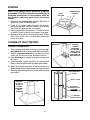
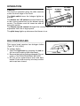
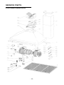
61000
Series
BROAN MFG. CO., INC.
1926 W. State St. Hartford, WI -53027
04306120
99042527A
READ AND SAVE THESE INSTRUCTIONS
WARNING
WARNING
TO REDUCE THE RISK OF FIRE, ELECTRICAL SHOCK, OR INJURY TO PERSONS, OBSERVE THE FOLLOWING:
1. Use this unit only in the manner intended
by the manufacturer. If you have questions, contact the manufacturer at the
address or telephone number listed in the
warranty.
2. Before servicing or cleaning unit, switch
power off at service panel and lock service panel to prevent power from being
switched on accidentally. When the service disconnecting means cannot be
locked, securely fasten a prominent
warning device, such as a tag, to the service panel.
3. Installation work and electrical wiring
must be done by a qualified person(s) in
accordance with all applicable codes and
standards, including fire-rated construction codes and standards.
4. Sufficient air is needed for proper combustion and exhausting of gases through
the flue (chimney) of fuel burning equipment to prevent backdrafting. Follow the
heating equipment manufacturer’s guidelines and safety standards such as those
published by the National Fire Protection
Association (NFPA), and the American
Society for Heating, Refrigeration and Air
Conditioning Engineers (ASHRAE), and
the local code authorities.
5. When cutting or drilling into wall or ceiling, do not damage electrical wiring and
other hidden utilities.
6. Ducted fans must always be vented to
the outdoors.
7. Do not use this unit with any solid-state
speed control device.
8. To reduce the risk of fire, use only steel
ductwork.
9. This unit must be grounded.
TO REDUCE THE RISK OF INJURY TO
PERSONS IN THE EVENT OF A RANGE
TOP GREASE FIRE, OBSERVE THE FOLLOWING:*
1. SMOTHER FLAMES with a close-fitting
lid, cookie sheet, or metal tray, then turn
off the burner. BE CAREFUL TO PREVENT BURNS. If the flames do not go
out immediately, EVACUATE AND CALL
THE FIRE DEPARTMENT.
2. NEVER PICK UP A FLAMING PAN - You
may be burned.
3. DO NOT USE WATER, including wet
dishcloths or towels - violent steam explosion will result.
4. Use an extinguisher ONLY if:
A. You know you have a Class ABC extinguisher and you already know how
to operate it.
B. The fire is small and contained in the
area where it started.
C. The fire department is being called.
D. You can fight the fire with your back
to an exit.
* Based on “Kitchen Fire Safety Tips”
published by NFPA.
CAUTION
1. For general ventilating use only. Do not
use to exhaust hazardous or explosive
materials and vapors.
2. To avoid motor bearing damage and
noisy and/or unbalanced impellers, keep
drywall spray, construction dust, etc. off
power unit.
3. Your hood motor has a thermal overload
which will automatically shut off the motor if it becomes overheated. The motor
will restart when it cools down. If the motor continues to shut off and restart, have
the hood serviced.
4. For best capture of cooking impurities,
the bottom of the hood should be a minimum of 24" and a maximum of 30" above
the cooking surface.
5. Two installers are recommended because of the large size and weight of this
hood.
6. Please read specification label on product for further information and requirements.
TO REDUCE THE RISK OF A RANGE TOP
GREASE FIRE:
1. Keep fan, filters and grease laden surfaces clean.
2. Always turn hood ON when cooking at
high heat.
3. Use high range settings on range only
when necessary. Heat oil slowly on low
to medium setting.
4. Don’t leave range unattended when cooking.
5. Always use cookware and utensils appropriate for the type and amount of food
being prepared.
-2-
INSTALL THE DUCTWORK
ROOF CAP
NOTE: To reduce the risk of fire, use only
steel ductwork.
1. Decide where the ductwork will run between
the hood and the outside.
2. A straight, short duct run will allow the hood
to perform most efficiently.
3. Long duct runs, elbows, and transitions will
reduce the performance of the hood. Use as
few of them as possible.
4. Install a roof or wall cap. Connect 6" round
steel ductwork to cap and work back towards
hood location. Use duct tape to seal the joints
between ductwork sections.
6" ROUND
DUCT
DECORATIVE
FLUE
WALL CAP
6" ROUND
ELBOW
HOOD
24" TO 30" ABOVE
COOKING SURFACE
INSTALL MOUNTING
BRACKETS
FRAMING BEHIND DRYWALL
L
C
L
1. Construct wood wall framing that is flush with
interior surface of wall studs.
Make sure:
a) the framing is centered over installation
location.
b) the height of the framing will allow the
mounting brackets to be secured to the
framing within the dimensions shown.
2. After wall surface is finished, secure mounting brackets to framing using dimensions
shown.
5
7
8
"
5
30
5
8
" to 3
6
5
8
" ab
7
8
"
ove
cook
top
305/8"= bottom of hood 24" above cooktop
365/8"= bottom of hood 30" above cooktop
RECTANGULAR CUTOUTS
MOUNTING
BRACKETS
INSTALL THE HOOD
3. Hang the hood from the brackets through the
rectangular cut-outs on the back of the
hood. Cut-outs are larger than the brackets
to allow for horizontal adjustment.
The bottom of the hood should be 24" to 30"
above the cooking surface.
4. Height adjustment screws provide vertical
adjustment.
5. Depth adjustment screws provide horizontal adjustment.
6. Secure the hood with additional mounting
screws. Use drywall anchors, provided, if
wall studs or framing are not available.
-3-
ADDITIONAL
MOUNTING
SCREWS
WALL FRAMING
DEPTH ADJUSTMENT
SCREWS
HEIGHT
ADJUSTMENT
SCREWS
ADDITIONAL
MOUNTING
SCREWS
WIRING
Note: This range hood must be properly
grounded. The unit should be installed by a
qualified electrician in accordance with all
applicable national and local electrical
codes.
1. Remove the wiring box cover. Remove a
knockout from the wiring box.
2. Feed 6" of power cable through the knockout opening and secure cable to the wiring
box with an appropriate connector.
3. Make electrical connections. Connect white
to white, black to black and green to green.
4. Replace wiring box cover and screws. Make
sure that wires are not pinched between
cover and box.
CONNECT DUCTWORK
DUCT
COLLAR
UPPER
BRACKET
Ducted Configuration
1. Use screws and wall anchors to secure upper bracket to the ceiling and wall as shown.
2. Use 6" round steel duct to connect the duct
collar on the hood to the ductwork above.
3. Use duct tape to make all joints secure and
air tight.
4. Connect the upper section of decorative
flue to the bracket with screws provided.
5. Slide the lower section of decorative flue
downward, until it fits properly around hood.
6. Secure decorative flue to hood with screws
provided.
WIRING BOX
COVER
FASTEN
UPPER
BRACKET
TO CEILING &
WALL WITH
SCREWS (&
ANCHORS IF
NECESSARY)
DECORATIVE
FLUE
DUCT TAPE
FASTEN
FLUE TO
HOOD &
UPPER
BRACKET
WITH
SCREWS
AIR VENT
POSITION FOR
DUCTED
CONFIGURATION
6" ROUND
STEEL DUCT
-4-
CONNECT DUCTWORK
UPPER
FLUE SECTION
UPPER
AIR
BRACKET
Ductfree Configuration
VENTS
(in upper flue section)
1. Use screws and wall anchors (supplied) to secure the upper bracket
to wall and ceiling as shown.
DUCTFREE
PLENUM
2. Turn upper flue section upside
down so air vents are at the top.
PLASTIC
MEASURE
Slide upper flue section into lower
DUCT COLLAR
flue section.
DUCT
LOWER
SEAM
3. Snap the plastic duct collar into the
FLUE SECTION
hole in the bottom of the ducfree plenum. Connect the ductfree plenum
6" ROUND
to the upper flue section with (4) flatSTEEL DUCT
head screws (supplied).
DISCHARGE
4. Measure the distance from the top
COLLAR
of the discharge collar to the ceiling. Cut a length of 6" round steel
duct 6" shorter than this dimension.
5. Fit duct section over the plastic duct
collar. For best fit, make sure duct
seam is toward the front.
6. Set duct/flue assembly on hood with top tilted away from wall. Reach around flue
to engage bottom of duct with discharge collar on hood. Tilt flue up against wall.
Upper flue section can be cut to length if necessary.
7. Raise upper flue section and screw it to upper bracket with (2) screws (supplied).
Screw lower flue section to hood with screws (supplied).
DUCTFREE FILTER
INSTALLATION
1. Purchase a ductfree filter kit (part no.
????) from your dealer.
2. Screw the plastic mounting brackets to
the blower inlet.
3. Position the filters over the mounting
brackets. Rotate mounting brackets to
lock filters in place.
-5-
MAINTENANCE
Grease Filters
The grease filters should be cleaned frequently.
Use a warm detergent solution. Grease filters
are dishwasher safe.
Remove filters by pushing filters towards the
back of hood and rotating filters downward.
GREASE FILTERS
Ductfree Filters
The ductfree filters should be changed every 6
months. Rotate the filters to remove and replace.
Hood Cleaning
Stainless steel is one of the easiest materials
to keep clean. Occasional care will help preserve its fine appearance.
Cleaning tips:
• Hot water with soap or detergent is all that is
usually needed.
• Follow all cleaning by rinsing with clear water. Wipe dry with a clean, soft cloth to avoid
water marks.
• For discolorations or deposits that persist,
use a non-scratching household cleanser or
stainless steel polishing powder with a little
water and a soft cloth.
• For stubborn cases, use a plastic scouring
pad or soft bristle brush together with cleaser
and water. Rub lightly in direction of polishing lines or "grain" of the stainless finish.
Avoid using too much pressure which may
mar the surface.
• DO NOT allow deposits to remain for long
periods of time.
• DO NOT use ordinary steel wool or steel
brushes. Small bits of steel may adhere to
the surface causing rust.
• DO NOT allow salt solutions, disinfectants,
bleaches, or cleaning compounds to remain
in contact with stainless steel for extended
periods. Many of these compounds contain
chemicals which may be harmful. Rinse with
water after exposure and wipe dry with a
clean cloth.
Painted surfaces should be cleaned with warm
water and mild detergent only.
-6-
DUCTFREE
FILTERS
OPERATION
BLOWER
ON / OFF
LIGHT
SWITCH
BLOWER
Controls
SWITCH
SPEED
The hood is operated using the slide controls
CONTROL
under the front edge of the hood.
The light switch turns the halogen lights on
and off.
The blower on / off switch turns the blower on
PILOT
to the running speed set by the blower speed
LAMP
control. The blower must be turned on and off
using this switch.
The blower speed control changes the running speed of the blower. It is infinitely
adjustable from low to high speed.
The pilot lamp lights up whenever the blower is on.
HALOGEN BULBS
This range hood requires two halogen bulbs
(Type T4, 12V, 20W).
To change bulbs:
1. Open the light lens by grasping the tab on
the lens and rotating lens downward.
2. Remove the bulb by pulling sideward (Do not
rotate). CAUTION: BULB MAY BE HOT!
3. Do not touch replacement bulb with bare
hands! Push bulb securely into lamp socket
and snap lens closed.
-7-
LIGHT LENS
TAB
WARRANTY
BROAN ONE YEAR LIMITED WARRANTY
Broan warrants to the original consumer purchaser of its products that such
products will be free from defects in materials or workmanship for a period of
one year from the date of original purchase. THERE ARE NO OTHER WARRANTIES, EXPRESS OR IMPLIED, INCLUDING, BUT NOT LIMITED TO,
IMPLIED WARRANTIES OR MERCHANT ABILITY OR FITNESS FOR A PARTICULAR PURPOSE.
During this one-year period, Broan will, at its option, repair or replace, without
charge, any product or part which is found to be defective under normal use
and service.
THIS WARRANTY DOES NOT EXTEND TO FLUORESCENT LAMP STARTERS AND TUBES. This warranty does not cover (a) normal maintenance and
service or (b) any products or parts which have been subject to misuse, negligence, accident, improper maintenance or repair (other than by Broan), faulty
installation or installation contrary to recommended installation instructions.
The duration of any implied warranty is limited to the one-year period as specified for the express warranty. Some states do not allow limitation on how long
an implied warranty lasts, so the above limitation may not apply to you.
BROAN’S OBLIGATION TO REPAIR OR REPLACE, AT BROAN’S OPTION,
SHALL BE THE PURCHASER’S SOLE AND EXCLUSIVE REMEDY UNDER
THIS WARRANTY. BROAN SHALL NOT BE LIABLE FOR INCIDENTAL,
CONSEQUENTIAL OR SPECIAL DAMAGES ARISING OUT OF OR IN CONNECTION WITH PRODUCT USE OR PERFORMANCE. Some states do not
allow the exclusion or limitation of incidental or consequential damages, so
the above limitation or exclusion may not apply to you.
This warranty gives you specific legal rights, and you may also have other
rights, which vary from state to state. This warranty supersedes all prior warranties.
To qualify for warranty service, you must (a) notify Broan at the address stated
below or telephone: 1-800-637-1453, (b) give the model number and part
identification and (c) describe the nature of any defect in the product or part.
At the time of requesting warranty service, you must present evidence of the
original purchase date.
BROAN MFG. CO., INC., 926 West State Street Hartford, WI 53027
-8-
SERVICE PARTS
61000 SERIES RANGE HOOD
KEY NO.
PART NO.
6
9
14
19
26
30
42
48
49
53
57
68
69
99
113
115
116
118
119
120
122
123
144
165
166
167
168
208
223
474
477
*
B02000191
B08087485
B02300730
B03295005
B02300722
B03292291
B03290377
B02310094
B03295000
B03202007
B02000756
B02000293
B02000294
BE3334372
B03202433
BE3495228
BE3334252
BE3342283
BE3342284
B03202118
B08089123
B03292283
B03292287
B03292161
B08086101
B03292162
B03292163
B02300717
B03292294
B02300719
B03295006
B06001768
*
B06106282
*
B06106286
*
B06106285
DESCRIPTION
Filter Spring
Grease Filter
Motor Capacitor
Terminal Box
Halogen Lamp Bulb
Switch Cover
Ductfree Filter Bracket
Motor
Blower Wheel
Rubber Washer
Damper Flap
Right Blower Housing
Left Blower Housing
Filter Channel
Nameplate
Wiring Box
Wiring Box Cover
Decorative Flue Bottom
Decorative FlueTop
Flue Mounting Bracket
Ductfree Plenum
Duct Connector
Wire Clamp
Control Board Box
Control Board
Control Board Box Cover
Capacitor Box Cover
Transformer
Switch Button
Halogen Lamp Housing
Terminal Cover
Blower Assembly (Includes Key Nos. 42, 48,
49, 53, 68, 69)
Control Board Assembly (Includes Key Nos.
144, 165, 166, 167, 168)
Switch Assembly (Includes Key Nos. 222, 223,
224, 225, 226, 228, 229, 230)
Motor Capacitor Assembly w/ Wires (Includes
Key No. 14 & Wires)
-9-
SERVICE PARTS
61000 SERIES RANGE HOOD
- 10 -