1
!"#$ %&'(
%&'(
%&'( )*+,- ./012- 34
./012- 56 .789:;<=8>?@- .A 5B?@- %&0CDEFGH IJ KLM
KLM
KLM NOPK PKQR STUVWXY=Z[\]= )^_`abcTUdRefgbhi!9hjk
lmn WXY=Z[\
o`]=
phqr
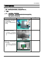
1. Precautions
1. Precautions
1-1. Safety Precautions
Follow these safety, servicing and ESD precautions to prevent damage and to protect against potential hazards such as
electrical shock.
1-1-1. Warnings
1. For continued safety, do not attempt to modify the circuit board.
2. Disconnect the AC power and DC power jack before servicing.
1-1-2. Servicing the LCD Monitor
1. When servicing the LCD Monitor, Disconnect the AC line cord from the AC outlet.
2. It is essential that service technicians have an accurate voltage meter available at all times. Check the calibration of this
meter periodically.
1-1-3. Fire and Shock Hazard
Before returning the monitor to the user, perform the following safety checks:
1. Inspect each lead dress to make certain that the leads are not pinched or that hardware is not lodged between the
chassis and other metal parts in the monitor.
2. Inspect all protective devices such as nonmetallic control knobs, insulating materials, cabinet backs, adjustment and
compartment covers or shields, isolation resistorcapacitor networks, mechanical insulators, etc.
3. Leakage Current Hot Check (Figure 1-1):
WARNING : Do not use an isolation transformer during this test.
Use a leakage current tester or a metering system that complies with American National Standards Institute (ANSI
C101.1, Leakage Current for Appliances), and Underwriters Laboratories (UL Publication UL1410, 59.7).
(READING SHOULD)
NOT BE ABOVE 0.5mA
LEAKAGE
CURRENT
TESTER
DEVICE
UNDER
TEST
TEST ALL
EXPOSED METAL
SURFACES
2-WIRE CORD
*ALSO TEST WITH
PLUG REVERSED
(USING AC ADAPTER
PLUG AS REQUIRED)
EARTH
GROUND
Figure 1-1. Leakage Current Test Circuit
4. With the unit completely reassembled, plug the AC line cord directly into a 120V AC outlet. With the unit’s AC switch first
in the ON position and then OFF, measure the current between a known earth ground (metal water pipe, conduit, etc.)
and all exposed metal parts, including: metal cabinets, screwheads and control shafts.
The current measured should not exceed 0.5 milliamp.
Reverse the power-plug prongs in the AC outlet and repeat the test.
1-1-4. Product Safety Notices
Some electrical and mechanical parts have special safetyrelated characteristics which are often not evident from visual
inspection. The protection they give may not be obtained by replacing them with components rated for higher voltage,
wattage, etc. Parts that have special safety characteristics are identified by
on schematics and parts lists. A substitute
replacement that does not have the same safety characteristics as the recommended replacement part might create
shock, fire and/or other hazards. Product safety is under review continuously and new instructions are issued whenever
appropriate.
1-1
1. Precautions
1-2. Servicing Precautions
WARNING: An electrolytic capacitor installed with the wrong polarity might explode.
Caution:
Before servicing units covered by this service manual, read and follow the Safety Precautions section of
this manual.
Note:
If unforeseen circumstances create conflict between the following servicing precautions and any of the
safety precautions, always follow the safety precautions.
1-2-1 General Servicing Precautions
1. Always unplug the unit’s AC power cord from the AC power source and disconnect the DC Power Jack before attempting
to:
(a) remove or reinstall any component or assembly, (b) disconnect PCB plugs or connectors, (c) connect a test
component in parallel with an electrolytic capacitor.
2. Some components are raised above the printed circuit board for safety. An insulation tube or tape is sometimes used.
The internal wiring is sometimes clamped to prevent contact with thermally hot components. Reinstall all such elements
to their original position.
3. After servicing, always check that the screws, components and wiring have been correctly reinstalled. Make sure that the
area around the serviced part has not been damaged.
4. Check the insulation between the blades of the AC plug and accessible conductive parts (examples: metal panels, input
terminals and earphone jacks).
5. Insulation Checking Procedure: Disconnect the power cord from the AC source and turn the power switch ON.
Connect an insulation resistance meter (500 V) to theblades of the AC plug.
The insulation resistance between each blade of the AC plug and accessible conductive parts (see above) should be
greater than 1 megohm.
6. Always connect a test instrument’s ground lead to the instrument chassis ground before connecting the positive lead;
always remove the instrument’s ground lead last.
1-3. Static Electricity Precautions
Some semiconductor (solid state) devices can be easily damaged by static electricity. Such components are commonly
called Electrostatically Sensitive Devices (ESD). Examples of typical ESD are integrated circuits and some field-effect
transistors. The following techniques will reduce the incidence of component damage caused by static electricity.
1. Immediately before handling any semiconductor components or assemblies, drain the electrostatic charge from your
body by touching a known earth ground. Alternatively, wear a discharging wrist-strap device. To avoid a shock hazard, be
sure to remove the wrist strap before applying power to the monitor.
2. After removing an ESD-equipped assembly, place it on a conductive surface such as aluminum foil to prevent
accumulation of an electrostatic charge.
3. Do not use freon-propelled chemicals. These can generate electrical charges sufficient to damage ESDs.
4. Use only a grounded-tip soldering iron to solder or desolder ESDs.
5. Use only an anti-static solder removal device. Some solder removal devices not classified as “anti-static” can generate
electrical charges sufficient to damage ESDs.
6. Do not remove a replacement ESD from its protective package until you are ready to install it. Most replacement ESDs
are packaged with leads that are electrically shorted together by conductive foam, aluminum foil or other conductive
materials.
7. Immediately before removing the protective material from the leads of a replacement ESD, touch the protective material
to the chassis or circuit assembly into which the device will be installed.
Caution: Be sure no power is applied to the chassis or circuit and observe all other safety precautions.
8. Minimize body motions when handling unpackaged replacement ESDs. Motions such as brushing clothes together,
or lifting your foot from a carpeted floor can generate enough static electricity to damage an ESD.
1-2
1. Precautions
1-4. Installation Precautions
1. For safety reasons, more than two people are required for carrying the product.
2. Keep the power cord away from any heat emitting devices, as a melted covering may cause fire or electric shock.
3. Do not place the product in areas with poor ventilation such as a bookshelf or closet. The increased internal temperature
may cause fire.
4. Bend the external antenna cable when connecting it to the product. This is a measure to protect it from being exposed to
moisture. Otherwise, it may cause a fire or electric shock.
5. Make sure to turn the power off and unplug the power cord from the outlet before repositioning the product. Also check
the antenna cable or the external connectors if they are fully unplugged. Damage to the cord may cause fire or electric
shock.
6. Keep the antenna far away from any high-voltage cables and install it firmly. Contact with the highvoltage cable or the
antenna falling over may cause fire or electric shock.
7. When installing the product, leave enough space (10cm) between the product and the wall for ventilation purposes.
A rise in temperature within the product may cause fire.
1-3
1. Precautions
Memo
1-4
2. Product specifications
2. Product specifications
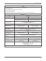
2-1. Feature & Specifications
Feature
ሪሪ Panel Specifications: 250 cd/m2, 5 ms, CR 1000:1, 170/160 (CR>10)
ሪሪ DPMS: Typical 0.3W
ሪሪ Off-Timer function for reducing standby power usages
ሪሪ DVI with HDCP (wide model)
ሪሪ Picture;a screen size desire
ሪሪ Supported Magic Bright3 / Eco Saving / Magic Angle / off timer / Image Size / Key Repeat Time
Specifications
Item
Description
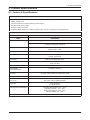
Model
S22A450BW
LCD Panel
TFT-LCD panel, RGB vertical stripe, normally white transmissive
22” Wide viewable
0.282(H)x0.282(V)mm pixel pitch
Scanning Frequency
Horizontal : 30kHz ~ 81kHz (Automatic)
Vertical: 56Hz ~ 75Hz
Display Colors
Maximum resolution
16.7 Million colors
Horizontal: 1680 Pixels
Vertical: 1050 Pixels
Input Signal
Input Sync Signal
Maximum Pixel Clock rate
Analog / DVI digital with HDCP
Seperate H/V sync, Composite H/V, Sync-on-Green
Level: TTL level
164Mhz
Active Display
(Horizontal/Vertical)
473.76(H) x 296.1(V)
AC power voltage &
Frequency
AC 100V~130V, 60Hz & AC, 200V~240V 50Hz
Power Consumption
MAX 27 W / Typical 22 W
Dimensions Set
(W x H x D)
Weight Set
Environmental Considerations
508 x 380 x 201 mm (With Stand)
508 x 344 x 50 mm (Without Stand)
4.6 kg (Product)
6.1 kg (Shipment)
Operating Temperature: 10°C ~ 50°C
Operating Humidity : 10% ~ 90%
Storage Temperature: -20°C ~ 45°C
Storage Humidity: 5% ~ 90%
Note: Designs and specifications are subject to change without prior notice.
2-1
2. Product specifications
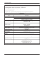
Feature
ሪሪ Panel Specifications: 250 cd/m2, 5 ms, CR 1000:1, 170/160 (CR>10)
ሪሪ DPMS: Typical 0.3W
ሪሪ Off-Timer function for reducing standby power usages
ሪሪ DVI with HDCP (wide model)
ሪሪ Picture;a screen size desire
ሪሪ Supported Magic Bright3 / Eco Saving / Magic Angle / off timer / Image Size / Key Repeat Time
Specifications
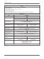
Item
Model
LCD Panel
Description
S24A450BW
S24A450B
TFT-LCD panel, RGB vertical stripe, normally white transmissive
24” wide viewable
0.270 (H) X 0.270 (V)mm pixel pitch
Scanning Frequency
24” wide viewable
0.276 (H) X 0.276 (V)mm pixel pitch
Horizontal : 30kHz ~ 81kHz (Automatic)
Vertical: 56Hz ~ 75Hz
Display Colors
Maximum resolution
Input Signal
Input Sync Signal
16.7 Million colors
Horizontal: 1920 Pixels
Horizontal: 1920 Pixels
Vertical: 1200 Pixels
Vertical: 1080 Pixels
Analog / DVI digital with HDCP
Seperate H/V sync, Composite H/V, Sync-on-Green
Level: TTL level
Maximum Pixel Clock rate
Active Display
(Horizontal/Vertical)
170MHz
518.4(H) X 324.0(V)mm
531.36(H) X 298.89(V) mm
AC power voltage &
Frequency
AC 100V~130V, 60Hz & AC, 200V~240V 50Hz
Power Consumption
34 W (Typical)
Dimensions Set
(W x H x D)
Weight Set
(After installation Stand)
Environmental Considerations
560 x 400 x 201 mm (With Stand)
560 x 374 x 50 mm (Without Stand)
570 x 387 x 201 mm (With Stand)
570 x 347 x 50 mm (Without Stand)
5.1 kg (Product)
6.7 kg (Shipment)
5.2 kg (Product)
6.8 kg (Shipment)
Operating Temperature: 10°C ~ 50°C
Operating Humidity : 10% ~ 90%
Storage Temperature: -20°C ~ 45°C
Storage Humidity: 5% ~ 90%
Note: Designs and specifications are subject to change without prior notice.
2-2
2. Product specifications
Feature
ሪሪ Panel Specifications: 250 cd/m2, 5 ms, CR 1000:1, 170/160 (CR>10)
ሪሪ DPMS: Typical 0.3W
ሪሪ Off-Timer function for reducing standby power usages
ሪሪ DVI with HDCP (wide model)
ሪሪ Picture;a screen size desire
ሪሪ Supported Magic Bright3 / Eco Saving / Magic Angle / off timer / Image Size / Key Repeat Time
Specifications
Item
Model
LCD Panel
Description
S19A450BW
S19A450BR
TFT-LCD panel, RGB vertical stripe, normally white transmissive
19” wide viewable
0.2835(H) X 0.2835 (V) mm pixel pitch
Scanning Frequency
19” normal viewable
0.294(H) X 0.294(V)mm pixel pitch
Horizontal : 30kHz ~ 81kHz (Automatic)
Vertical: 56Hz ~ 75Hz
Display Colors
Maximum resolution
Input Signal
Input Sync Signal
16.7 Million colors
Horizontal: 1440 Pixels
Horizontal: 1280 Pixels
Vertical: 900 Pixels
Vertical: 1024 Pixels
Analog / DVI digital with HDCP
Seperate H/V sync, Composite H/V, Sync-on-Green
Level: TTL level
Maximum Pixel Clock rate
Active Display
(Horizontal/Vertical)
140MHz
408.24(H) X 255.15(V)
376.31H) X 301.06(V)
AC power voltage &
Frequency
AC 100V~130V, 60Hz & AC, 200V~240V 50Hz
Power Consumption
20 W
Dimensions Set
(W x H x D)
Weight Set
(After installation Stand)
Environmental Considerations
443 x 377 x 201 mm (With Stand)
443 x 302 x 50 mm (Without Stand)
413 x 401 x 201 mm (With Stand)
413 x 348 x 50 mm (Without Stand)
4.3 kg (Product)
5.6 kg (Shipment)
4.7 kg (Product)
5.9 kg (Shipment)
Operating Temperature: 10°C ~ 50°C
Operating Humidity : 10% ~ 90%
Storage Temperature: -20°C ~ 45°C
Storage Humidity: 5% ~ 90%
Note: Designs and specifications are subject to change without prior notice.
2-3
2. Product specifications
Feature
ሪሪ Panel Specifications: 250 cd/m2, 5 ms, CR 1000:1, 170/160 (CR>10)
ሪሪ DPMS: Typical 0.3W
ሪሪ Off-Timer function for reducing standby power usages
ሪሪ DVI with HDCP (wide model)
ሪሪ Picture;a screen size desire
ሪሪ Supported Magic Bright3 / Eco Saving / Magic Angle / off timer / Image Size / Key Repeat Time
Specifications
Item
Description
Model
S19A200NW
LCD Panel
TFT-LCD panel, RGB vertical stripe, normally white transmissive
19” wide viewable
0.2835(H) X 0.2835 (V) mm pixel pitch
Scanning Frequency
Horizontal : 30kHz ~ 81kHz (Automatic)
Vertical: 56Hz ~ 75Hz
Display Colors
Maximum resolution
16.7 Million colors
Horizontal: 1440 Pixels
Vertical: 900 Pixels
Input Signal
Input Sync Signal
Maximum Pixel Clock rate
Analog / DVI digital with HDCP
Seperate H/V sync, Composite H/V, Sync-on-Green
Level: TTL level
136.75 Mhz
Active Display
(Horizontal/Vertical)
408.24(H) X 255.15(V)
AC power voltage &
Frequency
AC 100V~130V, 60Hz & AC, 200V~240V 50Hz
Power Consumption
20 W
Dimensions Set
(W x H x D)
Weight Set
(After installation Stand)
Environmental Considerations
443 x 395 x 201 mm (With Stand)
443 x 302 x 50 mm (Without Stand)
3.1 kg (Product)
4.2 kg (Shipment)
Operating Temperature: 10°C ~ 50°C
Operating Humidity : 10% ~ 90%
Storage Temperature: -20°C ~ 45°C
Storage Humidity: 5% ~ 90%
Note: Designs and specifications are subject to change without prior notice.
2-4
2. Product specifications
Feature
ሪሪ Panel Specifications: 250 cd/m2, 5 ms, CR 1000:1, 170/160 (CR>10)
ሪሪ DPMS: Typical 0.3W
ሪሪ Off-Timer function for reducing standby power usages
ሪሪ DVI with HDCP (wide model)
ሪሪ Picture;a screen size desire
ሪሪ Supported Magic Bright3 / Eco Saving / Magic Angle / off timer / Image Size / Key Repeat Time
Specifications
Item
Description
Model
S22A200B
LCD Panel
TFT-LCD panel, RGB vertical stripe, normally white transmissive
22” wide viewable
0.248(H) X 0.248(V) mm pixel pitch
Scanning Frequency
Horizontal : 30kHz ~ 81kHz (Automatic)
Vertical: 56Hz ~ 75Hz
Display Colors
Maximum resolution
16.7 Million colors
Horizontal: 1920 Pixels
Vertical: 1080 Pixels
Input Signal
Input Sync Signal
Maximum Pixel Clock rate
Analog / DVI digital with HDCP
Seperate H/V sync, Composite H/V, Sync-on-Green
Level: TTL level
148.5 Mhz
Active Display
(Horizontal/Vertical)
476.64(H) X 268.11(V)
AC power voltage &
Frequency
AC 100V~130V, 60Hz & AC, 200V~240V 50Hz
Power Consumption
25 W
Dimensions Set
(W x H x D)
Weight Set
(After installation Stand)
Environmental Considerations
513 x 410 x 201 mm (With Stand)
513 x 317 x 50 mm (Without Stand)
3.6 kg (Product)
5 kg (Shipment)
Operating Temperature: 10°C ~ 50°C
Operating Humidity : 10% ~ 90%
Storage Temperature: -20°C ~ 45°C
Storage Humidity: 5% ~ 90%
Note: Designs and specifications are subject to change without prior notice.
2-5
2. Product specifications
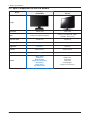
2-2. Spec Comparison to the Old Models
[SA450]
S22A450BW
[CREAM]
SN1933
1680 X 1050
1600 X 900
Analog / DVI digital with HDCP
Analog / DVI digital with HDCP
( 2033SN : Analog only )
Response Time
5ms(B to B)
5ms(B to B)
Viewing Angle
170/160(CR>10)
170/160(CR>10)
250 cd/m²
300 cd/m²
MEGA (DCR)
20000:1(DCR)
5 step
7 step
Magic Color
Image Size
Magic Bright3
Magic Tune (Premium)
ECO Saving
Magic Angle
Key Repeat Time
Magic Color
Color Effect
Image Size
Magic Bright2
Magic Tune (Premium)
Model
Design
Resolution
Input
Brightness
Contrast
MagicBright
Feature
2-6
2. Product specifications
2-3. Accessories
Product
Description
Code. No
Manual Flyer- Adapter Guide
BN68-03162J
Warranty Card
(Not available in all locations)
BN68-03548A
User’s Guide
BN46-00080A
Stereo Cable
BN39-00061C
Remark
Samsung Electronics
Service center
D-Sub(15 Pin) Cable
BN39-00244H
USB Cable
BN39-00397C
Power Cord
3903-000382
Adapter
BN44-00394F
2-7
'(
)*+,
)*+, -./ )%
)% -0123456789:;<=>?89
!"#$
%&'(
-@A
'(
-@A
'(
BCDEFGH
I$JKLM @NOPQRS
TU,V OPS WX,VY$HZ
[LM \]BC^_V `abcde fghij
klmFno
F
n pq[rs[_
tjV `abcde fghij
klmFno
F
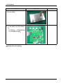
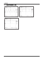
n 3. ^j
u vwxyEfghij
A `abcde fghijkl
mFno
Fn z{| !"# $%&$'()*+, -./*0 y12"# 3456*0789 :56*0789 y ;< =>? :56*0789
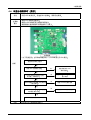
BG H IJKLMNOPQRS @ABCD $EF+
TU
:a-.b
'(*+VWX*+YZ
IJK
[\ ]J^_` -. %cde f"3 -. eIJKg[:7\'(hi -.:7*+[ jZ-.klf"mnopqrf"st
uvjwxy
:7
[
:56*07z{| }~ }~
:7P
$%*+X CN801
MGND1
1
LED3 2
3
4
LED2 5
LED1 6
MGND2
LED3
LED2
LED1
A2008WR0-6PS
LED4
LED4
AGND_GND
1/10W
POWER
560KOHM
R604
16V
C613
MAIN_5V_PW
L600
ADP_14V_PW
CN600
MAIN_5V_PW
+5V_MAIN
AGND_GND
C601
10UF
ADP_GND
C606
10UF
C602
C604
10UF
10UF
SS
VIN
EN
SW
COMP
GND
100NF
FB
C614
C615
10UF
10V
C617
ZD600
10UF
10V
R603
2.2KOHM
16V
C612
C616
10UF
10UF
10V
10V
C611
100NF
1/10W
50V
*
1/16W
R601
11KOHM
C609
BD620
0.01OHM
R602
10KOHM
8
7
6
5
1/16W
50V
25V
2.2NF
AGND_GND
AGND_GND
AGND_GND
25V
BST
MGND1
10UF
25V
25V
25V
3
4
C603
10UF
25V
ADP_VCC
MGND2
IC600
C610 100NF
1
16V
2
C605
1
3
2
4
22UH
BD9329EFJ
ADP_14V_PW
MGND1
47NF
AGND_GND
AGND_GND
CLOSE TO IC600 INPUT PIN
C650
100NF
16V
MAIN_5V_PW
C651
C652
10UF
10UF
AGND_GND
D650
S1G
400V
MAIN_5V_PW
4.7KOHM
*
10V
AGND_GND
1
2
3
ON/OFF
0.01OHM
VOUT
VSS
NC1
ADC_1.8V_PW
_1.8V_PW
IC602
R651
BD620
0.01OHM
10V
VIN
ADC_1.8V_PW
*
5
4
BD660
AGND_GND
C653
100NF
AGND_GND
16V
R652
4.7KOHM
C654
10UF
10V
10UF
10UF
10V
10V
C679
100NF
16V
AGND_GND
AGND_GND
AGND_GND
C678
C655
AGND_GND
AGND_GND
AGND_GND
CVDD_1.8V_PW
0.01OHM
*
CVDD_1.8V_PW
BD661
C672
10UF
10V
C673
100NF
16V
AGND_GND
+3.3V
AGND_GND
_3.3V_PW
OSC_VDD_3.3V_PW
0.01OHM
IC601
C621
10UF
C620
R621
4.7KOHM
1
2
3
ON/OFF
VOUT
VSS
NC1
VIN
*
5
_3.3V_PW
4
OSC_VDD_3.3V_PW
BD630
10V
100NF
C622
10UF
10V
AGND_GND
R622 AGND_GND
4.7KOHM
C623
100NF
16V
C624
C625
10UF
10UF
10V
100NF
16V
AGND_GND
10V
AGND_GND
AGND_GND
0.01OHM
AGND_GND
AGND_GND
C632
10UF
10V
AGND_GND
16V
C631
ADC_3.3V_PW
*
ADC_3.3V_PW
BD640
C641
C642
10UF
100NF
10V
16V
AGND_GND
AGND_GND
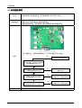
TU
*+WX ='( !" (,Z
:a.b
-. (,\'(hi -. (,op&$'(?7 -.?7^'(Kop&$'():7
:7
[
uvjwxy :56*07z{| }~ }~ ,-:;<
3456
72 !" !
"01
#$%& '(%&
)* + !,- .!,-/ 789
:7P
$%*+X 2 EDID_4.3V_PW
EDID_4.3V_PW
EDID_4.3V_PW
EDID_4.3V_PW
C112
IC100
R102
4.7KOHM
QZX363C6V8
6.8
DSUB_5V_PW
ZD100
DSUB_5V_PW
CN100
6
2
5
3
4
1/16W
R108
R119
1/16W
R110
1/16W
75OHM
1/16W
R112
1/16W
*
D101
HSYNC
VSYNC
C100
4.7NF
50V
C101
4.7NF
50V
390OHM
C111
10NF
50V
100OHM
C102
100OHM
C103
100OHM
C104
4.7NF
100OHM
C105
4.7NF
4.7NF
4.7NF
R113
56OHM
REDRED+
50V
GRNSOG1
50V
GRN+
50V
BLU-
50V
BLU+
HSYNC
56OHM
VSYNC
1KOHM
CHK_DSUB
MAIN_5V_PW
R121
2.2KOHM
MMBD4148SE
MMBD4148SE
R122
MMBD4148SE
1/16W
1/16W
10KOHM
C110
C109
15PF
22PF
50V
50V
MAIN_5V_PW
ZD102
C107
100NF
16V
AGND_GND
AGND_GND
27
28
29
30
31
32
33
34
35
36
37
38
C108
100NF
16V
AGND_GND
LVDS(DUAL)
AGND
CN401
BINSOGI
LV0M
GIN+
LV0P
GIN-
LV1M
RIN+
LV1P
RIN-
LV2M
DVDD
LV2P
DGND
HSYNCI
VSYNCI/TOUTP
LVCLK1M
LVCLK1P
LV03-_LVDS
LV03+_LVDS
LV04-_LVDS
LV04+_LVDS
LV3M
LV3P
LV4M
LV4P
LV5M
LV5P
AGND_GND
LV6M
LV6P
AGND_GND
LVDS(SINGLE)
CN400
BIN+
RSTB
DVDD_3.3V_PW
DDC_SDA_VGA
100OHM
1/16W
D102
PC7
RED-
DDC_SCL_VGA
22OHM
100OHM
R115
D100
PA0*/PWMC*
RED+
EDID_PROTECT
22OHM
R106
R114
BD101
PB5*/VGA_SDA*/TXD0*
GRN-
100OHM
R105
BD100
39
40
41
42
43
44
GRN+
1/16W
R111
*
R120
1/16W
R117
75OHM
C106
100NF
16V
SOG1
AGND_GND
WC_VGA
R104
DDC_SCL_A
R109
AGND_GND
BLU+
SDA
R107
75OHM
1/16W
ZD101
BLU-
SCL
GND
DDC_SDA_A
R118
DSUB_GND
DVDD_3.3V_PW
AGND_GND
AGND_GND
ADC_1.8V_PW
A2
100NF
16V
AGND_GND
AGND_GND
MGND1
DSUB
WP
8
7
6
5
100OHM
6
1
11
7
2
12
8
3
13
9
4
14
10
5
15
AGND_GND
VCC
A1
R101
PB4*/VGA_SCL*/RXD0*
KB-DS-008
MGND2
A0
1/16W
100OHM
R100
1
R103
4.7KOHM
1/16W
1
2
3
4
LVCLK2M
LVCLK2P
LV7M
LV7P
30
29
28
27
26
25
24
23
22
21
20
19
18
17
16
15
14
13
12
11
10
9
8
7
6
5
4
3
2
1
MGND2
30
29
28
27
26
25
24
23
22
21
20
19
18
17
16
15
14
13
12
11
10
9
8
7
6
5
4
3
2
1
PANEL_5V_PW
MGND2
MGND1
MGND1
AGND_GND
10KOHM
AGND_GND
4-5
①
④
③
TU
:a.b
*+WX ='( (,Z
-. (,\'(hi -. (,op&$'(?7 -.?7^'(Kop&$'():7
:7
[
uvjwxy :56*07z{| }~ }~
,-:;<
3456
72 !" !"01
+ !,- .!,-/ 2 789
:7P
$%*+X G12A2121
DELETE WHEN NO DVI CONNECTOR
CN200
MGND1
FT200
1
9
17
2
10
18
3
11
19
DVI_GND
4
12
20
DVI_5V_PW
5
DVI_5V_PW
13
21
6
14
22
7
15
23
8
16 R216
1KOHM
24
1
2
3
4
8
7
6
5
EXC28CG900U
D200
1
2
3
4
5
OUT_LINES
IN_LINES
IN_LINES
OUT_LINES
GND
GND
IN_LINES
OUT_LINES
IN_LINES
OUT_LINES
10
9
8
7
6
FT201
1
2
3
4
R202
10OHM
R204
R201
10OHM
R203
10OHM
R205
1
2
3
4
5
EXC28CG900U
IN_LINES
IN_LINES
OUT_LINES
OUT_LINES
GND
GND
IN_LINES
OUT_LINES
IN_LINES
DVI_RX1DVI_RX2+
DVI_RX1+
DVI_RX0+
OUT_LINES
10
9
8
7
6
AOZ8804DI
AGND_GND
AGND_GND
AGND_GND
AGND_GND
AGND_GND
R206
10OHM
R207
100OHM
10OHM
DVI_RXC+
DVI_RXC-
1/16W
MAIN_5V_PW
ZD200
*
DVI
MAIN_5V_PW
C208
100NF
D209
R210
1KOHM
1/16W
1
AGND_GND
6
R211
AGND_GND
2
5
3
4
CHK_DVI
100OHM
R208
100OHM
22OHM
DDC_SCL_D
R209
22OHM
DDC_SDA_D
R219
100OHM
R212
1/16W
1/16W
AGND_GND
R215
R214
AGND_GND
4.7KOHM
AGND_GND
AGND_GND
4.7KOHM
EDID_4.3V_PW
EDID_4.3V_PW
IC200
1
2
3
4
A0
A1
VCC
WP
A2
SCL
GND
SDA
8
7
6
5
WC_D
DDC_SCL_D
DDC_SDA_D
C206
100NF
16V
AGND_GND
AGND_GND
LVDS(DUAL)
LVDS(SINGLE)
CN400
LV0M
LV0P
LV1M
LV1P
LV2M
LV2P
LVCLK1M
LVCLK1P
LV03-_LVDS
LV03+_LVDS
LV04-_LVDS
LV04+_LVDS
LV3M
LV3P
LV4M
LV4P
LV5M
LV5P
LV6M
LV6P
LVCLK2M
LVCLK2P
LV7M
LV7P
30
29
28
27
26
25
24
23
22
21
20
19
18
17
16
15
14
13
12
11
10
9
8
7
6
5
4
3
2
1
CN401
MGND2
30
29
28
27
26
25
24
23
22
21
20
19
18
17
16
15
14
13
12
11
10
9
8
7
6
5
4
3
2
1
PANEL_5V_PW
MGND2
MGND1
MGND1
AGND_GND
10KOHM
C207
16V
100NF
*
1/16W
1/16W
R213
10KOHM
16V
4-8
DVI_RX2DVI_RX0-
D201
AGND_GND
8
7
6
5
AGND_GND
R217
DVI_HPD
R200
10OHM
10OHM
AOZ8804DI
1/16W
MGND2
10OHM
AGND_GND
AGND_GND
EDID_PROTECT
①
②
4-9
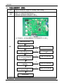
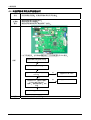
TU
:a.b
IJ
! =oKf" -.(,k'(hi -.op&$'( -.K(,op&$'():7
uvjwxy
:7
[
:56*07z{| }~ }~ @F:;<56
=>?;<56
>@
AB
C
DE @FG@ H
IJ
:7P
$%*+X 4
5
6
CN700
7
8
9
AGND_GND
PHONE_GND
3
11
1
10
2
PC_ARIN
PC_ALIN
PC_SOUND_INPUT
AUDIO
D702
D701
*
BD703
*
BD702
R716
R713
1/10W
R714
47KOHM
AGND_GND
1/10W
6.8KOHM
1/10W
6.8KOHM
LOW:SOUND ON
HIGH:SOUND OFF
AUDIO_EN
1/10W
R715
47KOHM
B
OPTION
220PF
50V
16V
1UF
AGND_GND
C702
C708
1/10W
R706
10KOHM
E
C
50V
220PF
C709
Q701
2SC2412K-Q
1/10W
R703
10KOHM
AUDIO_5V_PW
AUDIO_VOL
AUDIO_MUTE
LOW:SOUND ON
8
16V
16V
1UF
1
2
3
4
5
6
7
AGND_GND
ROUT/SHUTDOWN
VDD
RINROUT+
BYPASS
MGND1
SE/BTLGND
GND
LINLOUT+
VOLUME
VDD
VOLMAX
LOUT-
IC701
MUTE
AUDIO AMP
C705
100OHM
1/10W
C701 1UF 16V
100OHM
1/10W
AGND_GND
16V
1UF
R705
1/10W
R704 10KOHM
C700
1UF
R707
C710
HIGH:SOUND OFF
AGND_GND
16
15
14
13
12
11
10
9
50V
270PF
C711
1/10W
56OHM
E
C
50V
270PF
C712
16V
330UF
1/10W
56OHM
R708
16V
330UF
C704
Q700
2SA1980S-Y
B
BD706
1/10W
R700
100KOHM
BD701
0.01OHM
MAIN_5V_PW
1/10W
R701
100KOHM
AGND_GND
C703
R709
C706
16V
100UF
AUDIO_5V_PW
*
BD707
AGND_GND
D703
BD705
BD704
*
AGND_GND
D704
1/10W
ZD700
SE/BTL
PHONE_L+
PHONE_R+
SPK_L-
SPK_L+
SPK_R+
SPK_R-
R702
10KOHM
MGND2
4
3
2
1
MGND1
A2008WR0-4PS
3
11
1
10
2
AGND_GND
CN702
SPEAKER OUT
7
8
9
4
5
6
CN701
AGND_GND
GCC02-0077
4-11
UEJ-CV-047
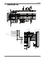
!
TU
:a.b
f" -. fO(,\'(
-. fO(,\'( -.
uvjwxy
:7
[
:56*07z{| }~ }~ ;<56
K ;<
56 AB
C
:7P
$%*+X DOWN_5V_PW
DOWN_5V_PW
100UF
16V
C551
C552
USB_D2USB_D2+
USBD2_GND
DOWN_5V_PW
1
2
CN501
MGND1
3
2
1
4
UAR27-4K5300
4
5
6
DOWN_5V_PW
FT501
UBBR-2004W-5S-T
D552
USB_5V
6
NUP4301MR6
2
1
D541
CN503
MGND1
FT503
2
1
USB3+_USB
D3_5V
1
2
3
4
MGND2
3 USB_D34 USB_D3+
3
USBD3_GND
AGND_GND
NUP4301MR6
DOWN_5V_PW
AGND_GND
16V
AGND_GND
AGND_GND
DOWN_5V_PW
USB_5V_PW
4
5
D553
6
100NF
UAR27-4K5300
2
1
1
3
AGND_GND
AGND_GND
AGND_GND
C542
C541
50V
C553
C554
USB3-_USB
100PF
USBUP_GND
AGND_GND
16V
100UF
AGND_GND
USB_UP+_USB
USB_5V_PW
USB_UP-
DOWN_5V_PW
16V
100NF
USB_UP-_USB
USB_UP+
MGND2
AGND_GND
4
3
NUP4301MR6
3
4
4
USB2+_USB
MGND1
1
2
3
4
MGND2
D2_5V
3
2
1
USB2-_USB
CN502
AGND_GND
FT502
2
AGND_GND
5
100NF
16V
USB_5V_PW
1/10W
R506
DP4_LEDGR
DP3_LEDGR
DP2_LEDGR
DP1_LEDGR
AGND_GND
SUSPEND
PVSS
VDD
VDDH
USB_DM
1KOHM
1/16W
R510
X501
R509
1/10W
47KOHM
16V
USB_3.3V_PW
AGND_GND
USB_UP-_USB
AGND_GND
AGND_GND
10KOHM
AGND_GND
USB_UP+_USB
50V
12MHZ
48
47
46
45
44
43
42
41
40
39
38
37
IC501
AGND_GND
R507
1/10W
AVSS
USB_DP
AVDD
AVSS
CHIPRESETN
16V
XSCI
1UF
AVSS
C510
DP2_DM
V_CTL
1/10W
DP2_DP
25
26
27
28
29
30
31
32
33
34
35
36
470KOHM
MGND1
AVDD
100KOHM
R508
VDD
DP1_PWRUP
DP2_OVRCUR
DP1_OVRCUR
E2PCLK
E2PDAT
EEPENABLE
VSSH
V33
V18
BUS_PWREDN
DP3_PWRUP
DP4_PWRUP
AVSS
XSCO
USB2-_USB
18PF
100NF
1/10W
OSC
DP2_PWRUP
DP4_OVRCUR
DP3_DM
USB1_DM
USB2+_USB
C502
C527
100KOHM
R505
DP3_OVRCUR
DP3_DP
USB1_DP
USB_3.3V_PW
DP4_DM
AVDD
USB3-_USB
DP4_DP
UP_RREF
USB3+_USB
AVDD
PVDD
12
11
10
9
8
7
6
5
4
3
2
1
AVDD5V
AGND_GND
C501
16V
AGND_GND
AGND_GND
13
14
15
16
17
18
19
20
21
22
23
24
10V
C504
4.7UF
1/10W
10KOHM
1/10W
18PF
100NF
R504
AGND_GND
50V
C526
USB_3.3V_PW
10UF
C509
100NF
C508
100NF
100NF
C507
R503
C506
10KOHM
C505
AGND_GND
1OHM
R501
100NF
16V
100NF
1/10W
BD501
16V
AGND_GND
C511
USB_5V_PW
10V
AGND_GND
AGND_GND
1UF
C503
C523
10KOHM
USB_3.3V_PW
USB_1.8V_PW
R524
10UF
10V
10UF
V_CTL
C522
OSC
C524
100KOHM
1/10W
100NF
R523
1/16W
R525
16V
C525
16V
1OHM
4.7KOHM
1UF
25V
100UF
C521
C529
10UF
1
2
3
1OHM
G
R521
D
S
1/10W
D
D
1/10W
D
R522
IC503
6
5
4
125V
F501
3A
AGND_GND
4-13
"#$%&'
"#$%&'
TUe&
TU ¡ ¢y £¤ ¥v ¦§fOIJK¨
*© ¡¢ªZL«¬ & fO
®¯°±v fO¢ª\
²³´µ TU WXIJKZ ¶op¢y '
·IJ¸¹ º £¤ ¥v(,«¬»¼'(
z½¾^*+C¿¦À?7fOÁ¢y
ZL«¬ & ÂÃÄÅ&$'((,
/4ÆÇÁ¢yfO?7¨ TU '(Z Ê«" £¤ $B_4§}O & ËÌ$B ¸¹ ºo#?7\{|Èb
ɦfOÁ¢yZIJ ()
()
!"#
!"#
ÍÎ
\ÏÐ
-.ÍÎ\opÑ&t )Ò¸ÓÆÔ\ÕÖ×ØÙIJK ØÙ
Ú{ÛÜÝ O
O @A Þß uàß áâBG H
ã" ±ä*+ XË*+
ÂÃ7V\åæÐç
-. $ èéÍÎ fO êeëfO -.xyopìí\ % îïfO OVð±CRS # fO " 7îïÂÅZñÌ òóôõ*ö÷øù[úûívüx\ &'( ýþ fOýþ ÿe 9 Ò/CfO J IJKaÍÎ
C'(K * %# K
'(IJK
¢y* $%&'
$%&'
$%&'
-.îï
-.îïæ
O V-. % îïæe-
e O ÍÎÞßeuàß áâBG H
34 ) IJ aã" 34 ±ä*+ Ò¸
fO¢yà\¢yaZ Ò¸LÌ{ZÖ ÂI\
Ì\ !"
#$
%&'
N *YÉNklÐ
yY ÂX± ÂÃ?7Z
ÂÃ?7Z
ÂÃ?7V ?7ÐçC@AYG H 7? +, ÇL ¿ZÖ¢ªL |ë fO
ñÌ K %# æÂÅ b!WX-./ " {|n# WX{| 9 {|$%Cb!$E-%&/Y b!{'-$/Y fO()*yC$EB
fOêV
+fOë
ÄRóý ,
fO
WX 01234'564 V-.Ð
Ð $ P-
$#n#. $P-w¡ "%!
MN-/
$EÂ
b!ûO9Y
% îï9 Cb!WX-)/Y b!MNY
ýe
0<V
ð±C+,ËN
fOîï ` 1647'8666 9 b! $ Y
b! $ 1OYC %5049$ B fO $ B0<
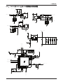
5. Wiring Diagram
5. Wiring Diagram
5-1. Wiring Diagram
5-1
5. Wiring Diagram
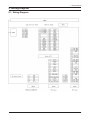
5-2. Board Connection
LVDS Connector
(Connect to Panel)
* For analog model, main PBA just has D-SUB Jack, no DVI Jack.
DVI Connector
(Connect to PC)
5-2
RGB Connector
(Connect to PC)
5. Wiring Diagram
5-3. Connector Functions
Connector
CN101 CN600
Functions
Supplies 5V from the power board to the main board and transmits the PWM output from the
power board to the inverter.
*When a problem occurs: The No Power and Blank Screen errors may occur.
CN1 ~ CN4 In
Transmits the lamp current (110mA ~ 112mA) generated in the inverter to the lamp of the
panel.
* When a problem occurs: The Blank Screen error may occur.
CN102
Transmits the input power of 90 to 263V to the power board.
* When a problem occurs: The No Power error may occur.
CN101
Connects to the function board.
* When a problem occurs: The No LED screen and Function failure errors may occur.
CN102
VGA signal input terminal
* When a problem occurs: The No RGB output error may occur.
CN400
Transmits the LVDS signals from the main board to the panel.
* When a problem occurs: The Blank screen and No Power errors may occur.
5-3