1
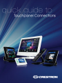
Crestron Quick Guide to Touchpanel Connections Crestron Electronics, Inc. 15 Volvo Drive Rockleigh, NJ 07647 1-888-CRESTRON All brand names, product names and trademarks are the property of their respective owners. ® ® Windows and Windows XP are registered trademarks of Microsoft Corporation in the United States and other countries. ©2009 Crestron Electronics, Inc. Crestron Quick Guide to Touchpanel Connections Contents INTRODUCTION.................................................................................................................................................. 1 TPMC‐8L ............................................................................................................................................................ 2 TPMC‐8X ............................................................................................................................................................ 4 TPMC‐8X‐DSW ................................................................................................................................................... 5 TPMC‐8T ............................................................................................................................................................ 7 TPMC‐12, TPS‐15, AND TPS‐17 ............................................................................................................................ 9 TPS‐12G‐QM AND TPS‐15G‐QM ......................................................................................................................... 14 TPMC‐CH‐IMC TOUCHPANEL INTERFACE ........................................................................................................... 18 TPS‐3000 AND TPS‐4000 .................................................................................................................................... 22 TPS‐IMPC TOUCHPANEL INTERFACE .................................................................................................................. 24 TPS‐4L ............................................................................................................................................................... 29 TPS‐6L ............................................................................................................................................................... 30 TPS‐6X‐DS AND TPS 6X‐DSW ............................................................................................................................. 33 TPS‐6X‐IMCW .................................................................................................................................................... 35 V‐PANELS .......................................................................................................................................................... 36 DIGITAL GRAPHICS ENGINES DGE‐1 AND DGE‐2 ................................................................................................. 37 TPMC‐4SM ........................................................................................................................................................ 40 CRESNET TOUCHPANEL POWER Q&A ................................................................................................................ 41 EXAMPLE HOOKUP AND APPLICATION DIAGRAMS ............................................................................................ 43 APPENDIX A: QUICKMEDIA INSTALLATION NOTES ............................................................................................. 54 FURTHER INQUIRIES .......................................................................................................................................... 54 Doc. 4903B Crestron Quick Guide to Touchpanel Connections Introduction This document contains detailed hookup information for the current line of Crestron touchpanels. Additional information may be found in the specific operations manual for each product, refer to the Crestron website (www.crestron.com). CAUTION: Do not apply excessive pressure to the touchscreen display during handling. Doing so can crack the screen and damage the touchpanel. NOTE: To prevent overheating, do not operate this product in an area that exceeds the environmental range: Temperature: 41° to 113°F (5° to 45°C), Humidity: 10% to 90% RH (non-condensing). Consideration must be given if installed in a closed or multi-unit rack assembly since the operating ambient temperature of the rack environment may be greater than the room ambient. NOTE: The maximum continuous current from equipment under any external load conditions shall not exceed a current limit that is suitable for the minimum wire gauge used in interconnecting cables. The ratings on the connecting unit's supply input should be considered to prevent overloading the wiring. Doc. 4903B 1 Crestron Quick Guide to Touchpanel Connections TPMC-8L Power One 2.5 mm barrel DC power jack; 12 Volt DC power input (power supply not included). One 2-pin 3.5 mm detachable terminal block 24 Volt DC power input; Wire size: 18 AWG maximum 12V 3.5A 24 VDC LAN One 8-wire RJ-45 with 2 LED indicators 10/100BaseT Ethernet port Green LED indicates link status Yellow LED indicates Ethernet activity 2 PIN SIGNAL PIN SIGNAL 1 TX + 5 N/C 2 TX - 6 RC - 3 RC+ 7 N/C 4 N/C 8 N/C Doc. 4903B Crestron Quick Guide to Touchpanel Connections USB USB is a connectivity specification developed by the USB Implementers Forum that provides a single, simple, standardized way to connect up to 127 devices to a computer. USB shielded cables contain two wires for power +5 volts (red) and ground (brown) and a twisted pair of wires (yellow and blue) that carry data. The USB standard supports data transfer rates of 12 Mbps (megabits per second). USB devices can be connected or disconnected without restarting the computer. Two USB 2.0 Type A female USB 2.0 ports for keyboard, mouse and external storage devices. PIN DESCRIPTION 1 +5 VDC 2 Data - 3 Data + 4 Ground AUDIO OUT (1) 5-pin 3.5 mm detachable terminal block; Balanced/unbalanced stereo line level audio output. Unbalanced Output 1 PIN DESCRIPTION L+ Left Positive L- Left Negative G Ground R+ Right Positive R- Right Negative Balanced Output 2 +-G+- 1 2 +-G+Shield + Chan 2 + Chan 2 + Chan 1 AMP + Doc. 4903B Chan 1 AMP 3 Crestron Quick Guide to Touchpanel Connections TPMC-8X NOTE: When inserting a Compact Flash card, orient the card so that the small lip at the top of the card is facing away from the touchpanel. The TPMC-8X should be used in a well-ventilated area. To prevent overheating, do not operate this product in an area that exceeds the environmental temperature range listed in the table of specifications. When making connections to the TPMC-8X, consider the following: Use the included Crestron power supply for these devices. The power supply cable cannot be extended. HEADPHONES (1) 3.5 mm TRS mini phone jack; Output power: 12 mW per channel; Minimum impedance: 32 Ω USB One USB 2.0 Type A female USB 2.0 port for keyboard, mouse and external storage devices. PIN DESCRIPTION 1 +5 VDC 2 Data - 3 Data + 4 Ground POWER One DC power jack (power pack included); power pack can also be used to charge internal battery. DOCKING STATION CONNECTOR Mates with TPMC-8X-DS or TPMC-8X-DSW Docking Station/Charger (sold separately). 4 Doc. 4903B Crestron Quick Guide to Touchpanel Connections TPMC-8X-DSW POWER One 2-pin 3.5 mm detachable terminal block 24 Volt DC power input Wire size: 18 AWG maximum 24 VDC NOTE: If the TPMC-8X-DSW is to be fed power from a Cresnet bus (the 24 and G lines), be sure that the Cresnet data lines (Y and Z) are not connected to the TPMC-8X-DSW, nor shorted together, to ground or to any metal surface. Be sure to isolate them properly and prevent them from shorting to anything. NOTE: The maximum continuous current from equipment under any external load conditions shall not exceed a current limit that is suitable for the minimum wire gauge used in interconnecting cables. The ratings on the connecting unit's supply input should be considered to prevent overloading the wiring. LAN One 8-wire RJ-45 with 2 LED indicators 10/100BaseT Ethernet port Green LED indicates link status Yellow LED indicates Ethernet activity. Doc. 4903B PIN SIGNAL PIN SIGNAL 1 TX + 5 N/C 2 TX - 6 RC - 3 RC+ 7 N/C 4 N/C 8 N/C 5 Crestron Quick Guide to Touchpanel Connections USB USB is a connectivity specification developed by the USB Implementers Forum that provides a single, simple, standardized way to connect up to 127 devices to a computer. USB shielded cables contain two wires for power +5 volts (red) and ground (brown) and a twisted pair of wires (yellow and blue) that carry data. The USB standard supports data transfer rates of 12 Mbps (megabits per second). USB devices can be connected or disconnected without restarting the computer. Two USB 2.0 Type A female USB 2.0 ports for keyboard, mouse and external storage devices. PIN DESCRIPTION 1 +5 VDC 2 Data - 3 Data + 4 Ground AUDIO OUT (1) 5-pin 3.5 mm detachable terminal block Balanced/unbalanced stereo line level audio output. PIN Unbalanced Output 1 DESCRIPTION L+ Left Positive L- Left Negative G Ground R+ Right Positive R- Right Negative Balanced Output 2 +-G+- 1 2 +-G+Shield + Chan 2 + Chan 2 + Chan 1 AMP + 6 Chan 1 AMP Doc. 4903B Crestron Quick Guide to Touchpanel Connections TPMC-8T * Crestron recommends using either the power jack on the base or on the side of the panel but not both at the same time. POWER 12V 3.5A Power jack (Power pack included) CAUTION: Use only Crestron power supplies for Crestron equipment. Failure to do so could cause equipment damage or void the Crestron warranty. Doc. 4903B 7 Crestron Quick Guide to Touchpanel Connections LAN One 8-wire RJ-45 with 2 LED indicators 10/100BaseT Ethernet port Green LED indicates link status Yellow LED indicates Ethernet activity. PIN SIGNAL PIN SIGNAL 1 TX + 5 N/C 2 TX - 6 RC - 3 RC+ 7 N/C 4 N/C 8 N/C USB USB is a connectivity specification developed by the USB Implementers Forum that provides a single, simple, standardized way to connect up to 127 devices to a computer. USB shielded cables contain two wires for power +5 volts (red) and ground (brown) and a twisted pair of wires (yellow and blue) that carry data. The USB standard supports data transfer rates of 12 Mbps (megabits per second). USB devices can be connected or disconnected without restarting the computer. Two USB 2.0 Type A female USB 2.0 ports for keyboard, mouse and external storage devices. PIN 8 DESCRIPTION 1 +5 VDC 2 Data - 3 Data + 4 Ground Doc. 4903B Crestron Quick Guide to Touchpanel Connections TPMC-12, TPS-15, and TPS-17 TPS-15 and TPS-17 TPMC-12 Doc. 4903B 9 Crestron Quick Guide to Touchpanel Connections RS-232 This 6-pin RJ-11 connector mates with a 9-pin serial port of a PC. The connecting cable is not supplied. Use this port to establish a direct connection between the touchpanel and a PC without a control system or network connection. Once the direct connection is established, touchpanel files and firmware updates can be uploaded to the touchpanel. Additionally, the touchpanel diagnostic tools can be accessed over the direct connection. PIN DESCRIPTION 1 CTS 2 GND 3 RXD 4 TXD 5 RTS 6 N/C (Not connected) LAN One 8-wire RJ-45 connector with two LED indicators: The green LED indicates network speed The yellow LED indicates Ethernet activity This connector provides an Ethernet 10baseT/100baseTX, full duplex, IEEE 802.3U compliant network connection. PIN SIGNAL PIN SIGNAL 1 TX + 5 N/C 2 TX - 6 RC - 3 RC+ 7 N/C 4 N/C 8 N/C NET The four-pin 5 mm detachable terminal block provides communication with and power from a Cresnet control network. Cresnet® Power Usage Not including TPMC-CH-IMC (1.0W) TPMC-12 = 43 W (1.8 A @ 24 V) Pins 24 and G provide 24 VDC and ground. TPS-15 = 65 W (2.7 A @ 24 V) Pins Y and Z provide communications (data). TPS-17 = 74 W (3.08 A @ 24 V) Crestron recommends an independent power supply for these touchpanels. 10 Doc. 4903B Crestron Quick Guide to Touchpanel Connections USB One Universal Serial Bus (USB) “B” connector provides a communications link. USB is a connectivity specification developed by the USB Implementers Forum that provides a single, simple, standardized way to connect devices to a computer. USB shielded cables contain two wires for power +5 volts (red) and ground (brown) and a twisted pair of wires (yellow and blue) that carry data. PIN 1 2 DESCRIPTION +5 VDC Data - PIN 3 4 DESCRIPTION Data + Ground NOTE: This connector is reserved for future applications. PHONE Connect this standard mini phone jack (12 mW, 32 ohm load) to the plug of a 3.5 mm external headphone set plug (not supplied). Plugging in the headphone cuts off the speakers. The headphone output is for WAV and Line audio only. It does not carry the microphone signal. Use the AUDIO OUT on the TPMC-CH-IMC for the microphone signal. MEMORY EXPANSION The onboard memory may be enhanced with the addition of a Type II compact flash memory (up to 160 MB). The flash memory slot is accessible on the rear panel of the unit. QM IN (QuickMedia Input) The eight-pin RJ-45 QuickMedia transport port accepts Crestron Certified Wiring carrying audio, video, and microphone signals. The QM input port conforms to the 568B wiring standard. Refer to the following table for connector pinouts. NOTE: The QM port is not connected through any “IMC” interface. NOTE: Only one video source may be displayed on the touchpanel at a time. NOTE: TPMC-12, TPS-15, and TPS-17 touchpanels do not support RGB. Doc. 4903B 11 Crestron Quick Guide to Touchpanel Connections RJ-45 QuickMedia Connector Pin Assignments RJ-45 Pin Wire colors QM ASSIGNMENT COMPOSITE, Number (EIA 568B) S-VIDEO, COMPONENT and AUDIO 1 WHITE/ORANGE - CHROMINANCE (- PR) 2 ORANGE + CHROMINANCE (+ PR) 3 WHITE/GREEN - LUMINANCE (- Y) 4 BLUE + AUDIO 5 WHITE/BLUE - AUDIO 6 GREEN + LUMINANCE (+ Y) 7 WHITE/BROWN - COMPOSITE (- PB) 8 BROWN + COMPOSITE (+ PB) RJ-45 MALE CONNECTOR VIDEO IN This eight-pin RJ-45 connection provides connectivity to the CNX-PVID or the TPMC-CHIMC interface module. This port provides component, composite or S-video balanced input to the touchpanel over Crestron Certified Wiring. Description of the pinouts is shown in the following table. A cable for this connection is provided with the touchpanel. CAUTION: Only use the TPMC-CH-IMC Interface Module when connecting this port. Use of other “IMC” products could damage the panel. Earlier IMC modules were equipped with a proprietary 10-pin RJ cable. If this is inadvertently connected to the 8-pin RJ-45 connector the panel will be damaged. NOTE: Only one video source may be displayed at a time. Video In Pin Assignments PIN 1 2 3 4 5 6 7 8 12 WIRE COLORS (568B) WHITE/ORANGE ORANGE WHITE/GREEN BLUE WHITE/BLUE GREEN WHITE/BROWN BROWN COMPOSITE S-VIDEO COMPONENT + Composite - Composite N/A N/A N/A N/A N/A N/A + Luminance - Luminance + Chrominance N/A N/A - Chrominance N/A N/A +Y -Y + PB + PR - PR - PB N/A N/A Doc. 4903B Crestron Quick Guide to Touchpanel Connections AUDIO I/O This 8-pin RJ-45 connector provides connectivity to the CNX-BIPAD or with the TPMC-CH-IMC interface module. This port uses Crestron Certified Wiring and provides audio input to the touchpanel and microphone output from the touchpanel. A description of the pinouts is shown in the following table. CAUTION: Only use the TPMC-CH-IMC Interface Module when connecting this port. Use of other “IMC” products could damage the panel. Audio In/Out Pin Assignments PIN WIRE COLORS (568B) 1 WHITE/ORANGE 2 PIN WIRE COLORS (568B) + Mic Left Out 5 WHITE/BLUE - Audio Left In ORANGE - Mic Left Out 6 GREEN - Mic Right Out 3 WHITE/GREEN + Mic Right Out 7 WHITE/BROWN + Audio Right In 4 BLUE + Audio Left In 8 BROWN - Audio Right In Doc. 4903B AUDIO I/O AUDIO I/O 13 Crestron Quick Guide to Touchpanel Connections TPS-12G-QM and TPS-15G-QM RS-232 This 6-pin RJ-11 connector mates with a 9-pin serial port of a PC. The connecting cable is not supplied. Use this port to establish a direct connection between the touchpanel and a PC without a control system or network connection. Once the direct connection is established, touchpanel files and firmware updates can be uploaded to the touchpanel. Additionally, the touchpanel’s diagnostic tools can be accessed over the direct connection. PIN 1 2 3 4 5 6 14 DESCRIPTION CTS GND RXD TXD RTS N/C (Not connected) Doc. 4903B Crestron Quick Guide to Touchpanel Connections LAN One 8-wire RJ-45 connector with two LED indicators: The green LED indicates network speed The yellow LED indicates Ethernet activity This connector provides an Ethernet 10baseT/100baseTX, full duplex, IEEE 802.3U compliant network connection. PIN SIGNAL PIN SIGNAL 1 TX + 5 N/C 2 TX - 6 RC - 3 RC+ 7 N/C 4 N/C 8 N/C NET The four-pin 5 mm detachable terminal block provides communication with and power from a Cresnet control network. Pins 24 and G provide 24 VDC and ground. Pins Y and Z provide communications (data). Cresnet® Power Usage Not including TPMC-CH-IMC (1.0W) TPS-12G-QM: 50 Watts (2.08 Amps @ 24 Volts DC) TPS-15G-QM: 75 Watts (3.13 Amps @ 24 Volts DC) TPS-12G-QM: PW-2420RU TPS-15G-QM: must use Cresnet power supply PC CARD Two Type II PCMCIA Card slots used for memory expansion up to 4GB or more, VT Pro-e project uploads, or installation of a wireless network card. A cover is secured over the slots to protect the electronics. Use a #1 Phillips screwdriver to remove the cover. The plate can be flipped and secured if only one slot needs to be accessed. CAUTION: PCMCIA cards are installed face down. Doc. 4903B 15 Crestron Quick Guide to Touchpanel Connections QM IN 1 and 2 (QuickMedia Inputs) Two 8-wire RJ-45 female, QuickMedia input ports; Signal types: Dynamically configurable under system control as: • One RGB (VGA) input with stereo program audio and two mic channels or • One auto-detecting component (YPbPr), S-video (Y/C) or composite video input with stereo program audio and two mic channels RGB format: RGBHV; RGB input resolution, non-interlaced: 640 x 480 minimum to 1600 x 1200 maximum (60 Hz limit at 1600 x 1200); Video/HDTV formats: 480i (NTSC), 576i (PAL), 480p, 576p, 720p and 1080i; Horizontal frequency: 15 - 100 kHz; Vertical frequency: 50 - 85 Hz; Delay skew compensation: 0 - 22 nS (QM IN 1 only, none on QM IN 2); Connects to QM output port of a QM-TX or other QuickMedia device (sold separately) via CresCAT-QM or CresCAT-IM cable; Maximum cable length: QM IN 1: 328 feet (aggregate distance from QM origination); QM IN 2: (Video/HDTV) 300 feet (aggregate distance from QM origination); (RGB @ 60 Hz) 216 feet for 640 x 480, 136 feet for 800 x 600, 84 feet for 1024 x 768, 50 feet for 1280 x 1024, 20 feet for 1600 x 1200 (using CresCAT-QM or CresCAT-IM cable) NOTE: The QM port is not connected through any “IMC” interface RJ-45 QuickMedia Connector Pin Assignments RJ-45 PIN NUMBER WIRE COLORS (EIA 568B) QM ASSIGNMENT COMPOSITE, S-VIDEO, COMPONENT AND AUDIO 1 WHITE/ORANGE - CHROMINANCE (- PR) 2 ORANGE + CHROMINANCE (+ PR) 3 WHITE/GREEN - LUMINANCE (- Y) 4 BLUE + AUDIO 5 WHITE/BLUE - AUDIO 6 GREEN + LUMINANCE (+ Y) 7 WHITE/BROWN - COMPOSITE (- PB) 8 BROWN + COMPOSITE (+ PB) RJ-45 MALE CONNECTOR QM OUT (QuickMedia Output One 8-wire RJ-45 female, QuickMedia output port containing RGB (same as touchscreen), WAV file audio and internal microphone signals; RGB format: RGBHV; RGB output resolution, non-interlaced (@ 60 Hz): TPS-12G-QM: 800 x 600 pixels TPS-15G-QM: 1024 x 768 pixels Connects to QM input port of any QuickMedia device via CresCAT-QM or CresCAT-IM cable. 16 Doc. 4903B Crestron Quick Guide to Touchpanel Connections PHONE Connect this standard mini phone jack to the plug of an external headphone set, not supplied. 105 mW per channel, 8 ohm load PWR (Power) (1) 2.1 mm barrel DC power jack, 24 Volt DC power input; Passes through to NET port to power Cresnet devices. CAUTION: Use only Crestron power supplies for Crestron equipment. Failure to do so could cause equipment damage or void the Crestron warranty. USB Ports Two USB Type A female, USB 1.1 ports for mouse or other external pointing device Doc. 4903B PIN DESCRIPTION 1 2 3 4 +5 VDC Data Data + Ground 17 Crestron Quick Guide to Touchpanel Connections TPMC-CH-IMC Touchpanel Interface NET This 4-position mini-terminal block connector is used to connect to other Cresnet peripherals in a system. Another NET connector is located on the other side of the module. Data and power for the TPMC-CH-IMC are provided via either connection. Pins 24 and G provide 24 VDC and ground. Pins Y and Z provide communications (data). 18 Doc. 4903B Crestron Quick Guide to Touchpanel Connections VIDEO The video input consists of three BNC connectors for unbalanced video signals. The component, composite or S-video input signal from an external video source is connected to these ports. AUDIO IN AUDIO IN Pinouts The 5-position mini-terminal block connector is wired to an external audio source and provides balanced and/or unbalanced audio input. Balanced Input 1 2 PIN DESCRIPTION L+ Left Positive L- Left Negative G Ground R+ Right Positive R- Right Negative Unbalanced Input 1 2 +-G+- +-G+Shield Source 1 + Source 1 + Jumpers Shield + Source 2 + Source 2 Shield Doc. 4903B 19 Crestron Quick Guide to Touchpanel Connections AUDIO OUT AUDIO OUT Pinouts The 5-position mini-terminal block connector mates with the included connector and provides balanced and/or unbalanced microphone output. Unbalanced Output 1 PIN DESCRIPTION L+ Left Positive L- Left Negative G Ground R+ Right Positive R- Right Negative Balanced Output 2 +-G+- 1 2 +-G+Shield + Chan 2 + AMP + Chan 2 AMP Chan 1 + Chan 1 VIDEO (To Panel) This RJ-45 connection mates with the TPMC-15-CH or TPMC-17-CH touchpanel. This port provides component, composite or S-video input to the touchpanel over CAT5 wiring. Video RJ-45 20 PIN WIRE COLORS (568B) WIRE COLORS (568A) 1 2 3 4 5 6 7 8 WHITE/ORANGE ORANGE WHITE/GREEN BLUE WHITE/BLUE GREEN WHITE/BROWN BROWN WHITE/GREEN GREEN WHITE/ORANGE BLUE WHITE/BLUE ORANGE WHITE/BROWN BROWN COMPOSITE + Composite - Composite N/A N/A N/A N/A N/A N/A S-VIDEO + Luminance - Luminance + Chrominance N/A N/A - Chrominance N/A N/A COMPONENT +Y -Y + PB + PR - PR - PB N/A N/A Doc. 4903B Crestron Quick Guide to Touchpanel Connections AUDIO (To Panel) This 8-pin RJ-45 connector mates with the TPMC-15-CH or TPMC-17-CH touchpanel. This port uses CAT5 wiring and provides audio input to the touchpanel and microphone output from the touchpanel. Audio In/Out PIN 1 2 3 4 5 6 7 8 WIRE COLORS (568B) WHITE/ORANGE ORANGE WHITE/GREEN BLUE WHITE/BLUE GREEN WHITE/BROWN BROWN WIRE COLORS (568A) WHITE/GREEN GREEN WHITE/ORANGE BLUE WHITE/BLUE ORANGE WHITE/BROWN BROWN AUDIO I/O + Mic Left Out - Mic Left Out + Mic Right Out + Audio Left In - Audio Left In - Mic Right Out + Audio Right In - Audio Right In The following chart shows the maximum recommended cable lengths for various signal formats. Recommended Maximum Cable Lengths for Audio/Video via CAT5 The maximum distance for CAT5 audio is limited to approximately 15 FORMAT MAXIMUM DISTANCE feet when connecting the AUDIO OUT port to a device with an Composite 750 feet unbalanced input. S-Video 750 feet If the AUDIO OUT port connects to a device with balanced inputs or no Component 500 feet Audio 1000 feet (balanced) Doc. 4903B device is connected, the maximum cable length for CAT5 audio is 1000 feet. 21 Crestron Quick Guide to Touchpanel Connections TPS-3000 and TPS-4000 NOTE: TPS-3000 and TPS-4000 include a TPS-IMPC Interface Module for system connection. Refer to page 24 for hookup details. NOTE: The audio connectors are color-coded blue. Hardware connections for the TPS-3000 and TPS-4000 (Back of the base is shown) HEADPHONES Connect this standard mini phone jack (12 mW, 32 ohms load) to the plug of an external headphone set, not supplied. The headphone output is for WAV and Line only. It does not send out the microphone signal. Use the MIC OUT on the TPS-IMPC for the microphone signal. NOTE: The headphone jack is unavailable after the HBK-3000 Hatchback option is installed. AUDIO This 8-position, RJ-45 connector (color coded blue) mates with the TPS-IMPC interface module and provides differential/single ended audio input and output. It also produces line level differential output. Pinout description is shown in the following table. 22 PIN # DESIGNATION 1 L+ DESCRIPTION Left Input (Positive) 2 L- 3 GND Ground Left Input (Negative) 4 R+ Right Input (Positive) 5 R- Right Input (Negative) 6 S 7 M+ Mic Output (Positive) 8 M- Mic Output (Negative) Shield Doc. 4903B Crestron Quick Guide to Touchpanel Connections RS-232 This 6-pin RJ-11 connector mates with a 9-pin serial port of a PC. The connecting cable is not supplied. Use this port to establish a direct connection between the touchpanel and a PC without a control system or network connection. Once the direct connection is established, touchpanel files and firmware updates can be uploaded to the touchpanel. Additionally, the touchpanel’s diagnostic tools can be accessed over the direct connection. PIN DESCRIPTION 1 CTS 2 GND 3 RXD 4 TXD 5 RTS 6 N/C (Not connected) NET/VIDEO This 10-position RJ-45 port provides network connection from the touchpanel to the interface module and network power to the touchpanel. This port also contains the composite and S-video inputs. Refer to the pinout and descriptions in the following table. CAUTION: The 10-pin RJ-45 connector cable supplied by Crestron is a custom cable and is the only one that should be used. The end of the cable has a metal shield that is required to protect the equipment. Using non-Crestron cables will result in damage to the product. Doc. 4903B PIN # DESIGNATION DESCRIPTION 1 +24V Power 2 GND Ground (Network) 3 C+ Chrominance (Positive) 4 C- Chrominance (Negative) 5 Y Data (Network) 6 Z Data (Network) 7 Y+ Luminance (Positive) Composite 8 Y- Luminance (Negative) Composite 9 GND Ground (Network) 10 +24V Power (Network) (Network) 23 Crestron Quick Guide to Touchpanel Connections TPS-IMPC Touchpanel Interface The TPS-IMPC is designed specifically to serve as an interface module for the Crestron tilt touchpanel. It is supplied with every Isys®-tilt touchpanel that includes audio capability. A network connector and video input connectors are located on one side of the unit. The opposite side offers audio input, microphone output (600 Ohms balanced and 300 Ohms unbalanced MIC OUT), and audio and network/video connections to the touchpanel. Cresnet Power Usage: <1 Watt @ 24 Volts DC – not including touchpanel. If power is applied to the 24 VDC jack and the NET port simultaneously, power will be drawn from whichever is highest. NTSC/PAL VIDEO The NTSC/PAL video input consists of three connectors; two BNC connectors for unbalanced video signals and one 6-pin mini-connector for twisted pair wiring of balanced video signals. The video signal is connected to these ports and requires a TPS-3000 or installation of the TPS-VID-1 or TPS-VID-2 video card in a TPS-5000 or TPS-6000 touchpanel to display video. Consult the latest revision of the TPS-3000 Operations Guide (Doc. 6076) or TPS-VID-1/2 Operations & Installation Guide (Doc. 6059) for details. Use either the two BNC connectors or the six-pin connector for twisted pair wiring when connecting a video source. 24 Doc. 4903B Crestron Quick Guide to Touchpanel Connections NOTE: The TPS-IMPC allows the use of either balanced or unbalanced signals for video input. To select the signal type to be used, the DIP switches located next to the MIC port must be set in the correct position. BAL/COAX DIP Switches These DIP switches are used to select which video connections (balanced or unbalanced) to use when receiving video signals. When used with a TPS-VID-2, each composite video signal can come in on either the twisted pair (balanced) or coaxial (unbalanced) connector. When used with a TPS-VID-1, the video signal (S-video or composite) can be received over the twisted pair (balanced) or coaxial (unbalanced) connectors. As long as a switch is in the appropriate position, a signal can be connected to either the BNC or twistedpair connector. To select the twisted pair connector for balanced video, the DIP switch for the respective video source must be in the “UP” position. To use the coaxial connector(s) for unbalanced video, the DIP switch must be in the “DOWN” position. NET This four-pin connector is used to connect to other Cresnet peripherals in a system and provide network power to the touchpanel if an external power pack is not used. Pins 24 and G provide 24 VDC and ground. Pins Y and Z provide communications (data). 24 VDC, 2.0A (Power Supply) This female connector is used to supply 24 VDC power to the TPS-IMPC and the touchpanel from an optional power pack (Crestron model PW-2420RU). When power is supplied to the TPS-IMPC through this connector, a Cresnet power connection on the NET connector is not required to display video on the touchpanel. CAUTION: Use only Crestron power supplies for Crestron equipment. Failure to do so could cause equipment damage or void the Crestron warranty. CAUTION: If power is provided to the TPS-IMPC from the +24VDC on a Cresnet connector or the PW-2420RU, power must not be applied to the power input on the touchpanel base. NOTE: When power is supplied through this connector, Crestron recommends disconnecting the +24 VDC on the Cresnet connector (if it is connected). NOTE: Use care in wiring installations to avoid applying 24 VDC power to Cresnet wiring from multiple sources. Doc. 4903B 25 Crestron Quick Guide to Touchpanel Connections NET/VIDEO (To Panel) This 10-pin RJ-45 connection mates with the TPS-3000, TPS-5000, or TPS-6000 touchpanel. Refer to the descriptions and pinout table that follow this paragraph. The 10-pin net/video cable assembly to connect the touchpanel to the TPSIMPC is supplied. This port provides the Cresnet connection to the touchpanel. This port also provides composite or S-video input for the built-in video card (with the purchase of a TPS-3000 or installation of the TPS-VID-1/2 in a TPS-5000 or TPS-6000 touchpanel). CAUTION: It is possible to mistakenly insert the 8-pin audio cable into this port. Consult the latest revision of the TPS-3000 Operations Guide (Doc. 6076) or TPS-VID-1/2 Operations & Installation Guide (Doc. 6059) for details. NET/VIDEO PIN DESIGNATION DESCRIPTION 1 +24V Power (Network) 2 GND Ground (Network) 3 C+ Chrominance (Positive) /Composite 2 4 C- Chrominance (Negative) /Composite 2 5 Y Data (Network) 6 Z Data (Network) 7 Y+ Luminance (Positive) /Composite 1 8 Y- Luminance (Negative) /Composite 1 9 GND Ground (Network) 10 +24V Power (Network) To determine the location of pin 1, hold the cable so that the end of the 10-pin RJ-45 connector is facing away from you, with the clip side down and the copper side up. The copper connector on the far left is pin 1. CAUTION: The 10-pin RJ-45 net/video connector cable supplied by Crestron is a custom cable and is the only one that should be used. The end of the cable has a metal shield that is required to protect the equipment. Using non-Crestron cables will result in damage to the product. 26 Doc. 4903B Crestron Quick Guide to Touchpanel Connections AUDIO (To Panel) This 8-pin RJ-45 mates with the TPS-3000, TPS-5000, or TPS-6000 touchpanel. The 8-pin audio cable assembly is supplied. Even though the 10-pin net/video cable may fit into the port, do not use it. This port provides audio input to the touchpanel and microphone output from the touchpanel. A description of the pinouts is shown in the following table. To determine the location of pin 1, hold the cable so that the end of the 8-pin RJ-45 connector is facing away from you, with the clip side down and the copper side up. The copper connector on the far left is pin 1. AUDIO (To Panel) PIN DESIGNATION DESCRIPTION 1 L+ Left Input (Positive) 2 L- Left Input (Negative) 3 GND/Shield 4 R+ Right Input (Positive) 5 R- Right Input (Negative) 6 GND/Shield 7 M+ Mic Output (Positive) 8 M- Mic Output (Negative) Audio Input Ground/Shield Mic Output Ground/Shield AUDIO INPUT The port mates with a six-pin connector (supplied) and provides balanced and/or unbalanced audio input. AUDIO INPUT PIN DESCRIPTION S Shield R+ Right Positive R- Right Negative L+ Left Positive L- Left Negative S Shield Balanced Input 1 2 Unbalanced Input 1 +-G+- 2 +-G+- Shield Source 1 + Source 1 + Jumpers Shield + Source 2 + Source 2 Shield Doc. 4903B 27 Crestron Quick Guide to Touchpanel Connections MIC OUT The port mates with a three-pin connector (supplied) and produces line level differential output. MIC OUT Pinouts PIN 28 DESCRIPTION + Positive - Negative S Shield Doc. 4903B Crestron Quick Guide to Touchpanel Connections TPS-4L LAN (Ethernet) One 8-wire RJ-45 connector with two LED indicators (green LED indicates network speed, yellow LED indicates Ethernet activity). This connector provides an Ethernet 10baseT/100baseTX, full duplex, IEEE 802.3U compliant network connection. NOTE: This port does not support a wireless Ethernet connection. LAN Connector Pinouts PIN SIGNALS PIN SIGNALS 1 TX + 5 N/C 2 TX - 6 RC - 3 RC + 7 N/C 4 N/C 8 N/C NET This 4-position mini-terminal block connector provides Cresnet network connection from the touchpanel as well as power to the touchpanel. Pins 24 and G provide 24 VDC and ground. Pins Y and Z provide communications (data) Doc. 4903B 29 Crestron Quick Guide to Touchpanel Connections TPS-6L LAN (Ethernet) One 8-wire RJ-45 connector with two LED indicators (green LED indicates network speed, yellow LED indicates Ethernet activity). This connector provides an Ethernet 10baseT/100baseTX, full duplex, IEEE 802.3U compliant network connection. LAN Connector Pinouts PIN SIGNALS 30 PIN SIGNALS 1 TX + 5 N/C 2 TX - 6 RC - 3 RC + 7 N/C 4 N/C 8 N/C Doc. 4903B Crestron Quick Guide to Touchpanel Connections NET This 4-position mini-terminal block connector provides Cresnet network connection from the touchpanel as well as power to the touchpanel. Pins 24 and G provide 24 VDC and ground. NET 24 Y Z G Pins Y and Z provide communications (data) MIC OUT This 3-position mini-terminal block connector provides balanced line level microphone output with AGC. PIN # DESIGNATION DESCRIPTION 1 + Mic Output (Positive) 2 - Mic Output (Negative) 3 S Shield AUDIO INPUT One 5-pin 3.5mm detachable terminal block Balanced/unbalanced stereo (summed to mono) line-level input (requires SPK-6L); Input Impedance: 10k ohms balanced, 5k ohms unbalanced; Maximum Input Level: 2 Vrms balanced/unbalanced; Normally connects to a Crestron CAT5 balanced audio source via CresCAT cable; Maximum CAT5 Cable Length: 1000 feet. PIN # DESIGNATION 1 R+ Right Input (Positive) 2 R- Right Input (Negative) 3 S Shield 4 L+ Left Input (Positive) 5 L- Left Input (Negative) Balanced Input 1 2 DESCRIPTION Unbalanced Input 1 +-G+- 2 +-G+- Shield Source 1 + Source 1 + Jumpers Shield + Source 2 + Source 2 Shield Doc. 4903B 31 Crestron Quick Guide to Touchpanel Connections NTSC/PAL INPUT One 5-pin 3.5mm detachable terminal block Balanced (CAT5) or unbalanced (coaxial) composite video inputs Formats: NTSC 480i or PAL 576i Input Impedance: 100 ohms balanced, 75 ohms unbalanced Input Level: 1 Vp-p nominal Balanced input normally connects to a Crestron CAT5 balanced video source via CresCAT cable, using +, -, and S connections. Unbalanced video uses S (shield) and C connections. Maximum CAT5 Cable Length: 750 feet. Optional External Speaker One six-pin (2x3) rectangular connector for optional external speaker kit (SPK-6L, sold separately). 32 Doc. 4903B Crestron Quick Guide to Touchpanel Connections TPS-6X-DS and TPS 6X-DSW TPS-6X-DS TYPE Interface Module Connector (to TPS-6X-IMCW) 10-Position RJ-50 PIN Color SIGNAL 1 Gray Ground 2 Orange/White Ethernet TX+ 3 Orange Ethernet TX- 4 Green/White Ethernet RX+ 5 Blue Cresnet Y 6 Blue/White Cresnet Z 7 Green Ethernet RX- 8 Brown/White Diff Video + 9 Brown Diff Video - 10 Gray/White Power 12VDC/24VDC TPS-6X-DSW Doc. 4903B 33 Crestron Quick Guide to Touchpanel Connections NET This 4-position mini-terminal block connector provides Cresnet network connection from the touchpanel as well as power to the touchpanel. Pins 24 and G provide 24 VDC and ground. NET 24 Y Z G Pins Y and Z provide communications (data) VID IN (unbalanced) Unbalanced composite video input Input impedance: 75 Ω nominal Input level: 1 Vp-p nominal, 1.5 Vp-p maximum Maximum DC offset: ±2 Volts Connects to any conventional coax video source (S=shield) VID IN (balanced) Balanced composite video input Input impedance: 100 Ω nominal Input level: 1 Vp-p nominal, 1.5 Vp-p maximum Maximum DC offset: ±2 Volts ® Connects to any Crestron CH CAT5 Video Out port via CresCAT cable (S=shield) LAN (Ethernet) One 8-wire RJ-45 connector provides an Ethernet 10baseT/100baseTX, full duplex, IEEE 802.3U compliant network connection. LAN Connector PIN 34 SIGNALS PIN SIGNALS 1 TX + 5 N/C 2 TX - 6 RC - 3 RC + 7 N/C 4 N/C 8 N/C Doc. 4903B Crestron Quick Guide to Touchpanel Connections TPS-6X-IMCW TYPE PIN Color SIGNAL Interface Module Connector (to TPS-6X-IMCW) 10-Position RJ-50 1 2 3 4 5 6 7 8 9 10 Gray Orange/White Orange Green/White Blue Blue/White Green Brown/White Brown Gray/White Ground Ethernet TX+ Ethernet TXEthernet RX+ Cresnet Y Cresnet Z Ethernet RXDiff Video + Diff Video Power 12VDC/24VDC NET This 4-position mini-terminal block connector provides Cresnet network connection from the touchpanel as well as power to the touchpanel. Pins 24 and G provide 24 VDC and ground NET 24 Y Z G Pins Y and Z provide communications (data) VID IN (unbalanced) Unbalanced composite video input Input impedance: 75 Ω nominal Input level: 1 Vp-p nominal, 1.5 Vp-p maximum Maximum DC offset: ±2 Volts Connects to any conventional coax video source (S=shield) VID IN (balanced) Balanced composite video input Input impedance: 100 Ω nominal Input level: 1 Vp-p nominal, 1.5 Vp-p maximum Maximum DC offset: ±2 Volts ® Connects to any Crestron CH CAT5 Video Out port via CresCAT cable (S=shield) Power One on front panel and one on back panel. 2.5 mm barrel DC power jack, 12 Volt DC power input; (PW-1215 or PWI-1215 power supply sold separately); Passes through panel port to power TPS-6X. Doc. 4903B 35 Crestron Quick Guide to Touchpanel Connections V-Panels Available as 12" and widescreen 15" displays in black or white. V-Panel displays are ultra-thin and may be installed flush mount, on a standard VESA mount or a desktop tiltcase. The new sleek design is accomplished by separating the Digital Graphics Engine (DGE), which is rack mounted up to 200 feet away. Either the DGE-1 or DGE-2 may be combined with a V-Panel display and feature a Windows Embedded platform to deliver PC applications, Web browsing, streaming media, VoIP and onscreen annotation. DGE-1 provides one scalable analog video window display, and the DGE-2 delivers two scalable 1080p HD video window displays. DMNet Port Connections PIN Number Signal Wire Color 24 +24VDC Red A Data Orange B Data Grey G Ground Black NOTE: DMNet™ uses the same physical connectors as Cresnet®, but the two protocols are not compatible. Be sure you do not cross-wire DMNet and Cresnet. D and M Port Connections PIN Number Color PIN Number Color 1 White/Orange 5 White/Blue 2 Orange 6 Green 3 White/Green 7 White/Brown 4 Blue 8 Brown PIN DESCRIPTION 1 2 3 4 +5 VDC Data Data + Ground USB Type A female, USB 1.1 ports for mouse or touchscreen input 36 Doc. 4903B Crestron Quick Guide to Touchpanel Connections Digital Graphics Engines DGE-1 and DGE-2 DGE-1 D and M Ports PIN WIRE COLOR 1 Orange/White 2 Orange 3 Green/White 4 Blue 5 Blue/White 6 Green 7 Brown/White 8 Brown PIN SIGNAL DESCRIPTION WIRE COLOR 24 +24 VDC DC Power Red A DM_NET+ DMNet Orange B DM_NET- DMNet Grey G GND DC Ground Black 24 A B G Port NOTE: DMNet uses the same physical connectors as Cresnet, but the two protocols are not compatible. Be sure that you do not cross-wire DMNet and Cresnet AUDIO IN/OUT PIN # DESIGNATION DESCRIPTION 1 R+ Right Input (Positive) 2 R- Right Input (Negative) 3 S Shield 4 L+ Left Input (Positive) 5 L- Left Input (Negative) NET Two 4-position mini-terminal block connectors provides Cresnet network connection. Pins 24 and G provide 24 VDC and ground. NET 24 Y Z G Pins Y and Z provide communications (data) Doc. 4903B 37 Crestron Quick Guide to Touchpanel Connections LAN (Ethernet) One 8-wire RJ-45 connector provides an Ethernet 10baseT/100baseTX, full duplex, IEEE 802.3U compliant network connection. PIN SIGNALS PIN SIGNALS 1 TX + 5 N/C 2 TX - 6 RC - 3 RC + 7 N/C 4 N/C 8 N/C Audio I/O PIN WIRE COLORS (568B) AUDIO I/O PIN WIRE COLORS (568B) AUDIO I/O 1 WHITE/ORANGE + Mic Left Out 5 WHITE/BLUE - Audio Left In 2 ORANGE - Mic Left Out 6 GREEN - Mic Right Out 3 WHITE/GREEN + Mic Right Out 7 WHITE/BROWN + Audio Right In 4 BLUE + Audio Left In 8 BROWN - Audio Right In DGE-2 38 Doc. 4903B Crestron Quick Guide to Touchpanel Connections Basic V-Panel Hookup Example Doc. 4903B 39 Crestron Quick Guide to Touchpanel Connections TPMC-4SM LAN (Ethernet) One 8-wire RJ-45 connector provides an Ethernet 10baseT/100baseTX, full duplex, IEEE 802.3U compliant network connection. LAN Connector PIN SIGNALS PIN SIGNALS 1 TX + 5 N/C 2 TX - 6 RC - 3 RC + 7 N/C 4 N/C 8 N/C OCCUPANCY SENSOR INPUT (4) Captive screw terminals comprising (2) voltage sensing inputs (referenced to ground) with 24 Volt DC power output Input voltage range: 0-30 Volts DC Sensing threshold: ≥ 4.5 Volts DC active, ≤ 1 Volt DC inactive Maximum DC load: 4 Watts @ 24 Volts DC, provides operating power for up to (4) Crestron GLS Series occupancy sensors 40 Doc. 4903B Crestron Quick Guide to Touchpanel Connections Cresnet Touchpanel Power Q&A Q. We prefer to place Cresnet power supplies in our “Head End” equipment rack for large residential systems. It has come to our attention that many of the newer touchpanels draw considerably more Cresnet power then their predecessors. (For instance, the TPS-15G-QM draws 75 watts of Cresnet power.) Considering power loss (due to resistance) in cable, and the 75 Watt maximum output of Crestron power supplies, it appears that the maximum distance between a power supply and a newer touchpanels will be much less than previous. 1. Why does the TPMC-15/17 (CH/QM) come with its own 12.5 Volt power supply, instead of using Cresnet power? 2. Is there any possibility of producing a larger power supply to deal with the incresed Cresnet power consumption? 3. Does Crestron have any recommendations or guidelines regarding power delivery over Cresnet (and other) cable? 1. The higher resolution, brightness, and added capabilities of the new Crestron touchpanels have come at a price. More power is needed to drive these devices. This is especially true for the wired “TPMC” panels. Their embedded computer capabilities draw a great deal of power. Their power draw makes it impractical to drive them with 24 Volt Cresnet power. A dedicated 12.5 Volt power supply was chosen as the best way to supply power. A. TPMC-15CH/QM-(L) and TPMC-17CH/QM-(L) panels are shipped with an interface module called a TPMCL-IMC. This interface is used to convert the power from the panels power supply to two wires, allowing for extensions in distance between the power supply and the panel. The following chart illustrates cablelength limitations: Recommended wire lengths between TPMC-L-IMC and TPMC touchpanel. WIRE GAUGE SINGLE WIRE DOUBLE WIRE 14awg (2.5mm) 30ft 60ft 16awg (1.5mm) 20ft 40ft 2. The answer is “no”. The National Electrical Code prohibits running more than 75 Watts of Cresnet power through low-voltage wiring. Larger power supplies could present a fire hazard. 3. When “sizing up” an installation, pay attention to the touchpanel sizes and their distance from the main equipment rack. In many cases, it may be best to locate a power supply local to the touchpanel. In multi-story projects, utility closet locations should be noted as a possible site for Cresnet power supplies on that floor. In some cases, it may make sense to use larger gauge wiring for Cresnet power on long runs. Use the following formula to determine the maximum length of wire that you can use to send power from a dedicated 75 Watt power supply to a specific touchpanel. L < 40,000/(PF x R) Where: “L”= length in feet, “PF”= Crestron ‘Power Factor’, “R”= Cable “Resistance” Refer to the following table for maximum cable lengths. Doc. 4903B 41 Crestron Quick Guide to Touchpanel Connections Maximum Cable Lengths for TPS panels using 75 watts of Cresnet Power Cresnet (18 awg R=6) 16 awg (R=4) CAT5 (2-cond R=13) 12 awg (R=1.6) TPS-12 (L) 155’ 232’ 71’ 580’ TPS-15 (L) 102’ 153’ 47’ 384’ TPS-17 (L) 88’ 135’ 40’ 333’ TPS-12G-QM (L) 133’ 200’ 61’ 500’ TPS-15G-QM (L) 88’ 133’ 40’ 333’ 42 Doc. 4903B Crestron Quick Guide to Touchpanel Connections Example Hookup and Application Diagrams TPS-12G-QM and TPS-15G-QM Interface: QuickMedia Device Doc. 4903B 43 Crestron Quick Guide to Touchpanel Connections TPS-12G-QM and TPS-15G-QM Interface: Extended Application Dual Video/RGB Windows and Audience Presentation 44 Doc. 4903B Crestron Quick Guide to Touchpanel Connections TPS-12G-QM and TPS-15G-QM Kitchen Control Application TPS-12G-QM or TPS-15G-QM Podium Application – with QM-MD7X2 Switcher for Multiple AV Inputs Doc. 4903B 45 Crestron Quick Guide to Touchpanel Connections TPMC-CH-IMC Interface Connections for TPS-12, TPS-15, and TPS-17 46 Doc. 4903B Crestron Quick Guide to Touchpanel Connections QuickMedia Interface Connections for TPS-12, TPS-15, and TPS-17 Doc. 4903B 47 Crestron Quick Guide to Touchpanel Connections Balanced AV Distribution Connections for TPS-12, TPS-15, and TPS-17 (CNX-BIPAD8 and CNX-PVID8) 48 Doc. 4903B Crestron Quick Guide to Touchpanel Connections Balanced CAT5 AV Distribution Connections for TPS-12, TPS-15, and TPS-17 (C2N-IADS30X24 and C2N-IVDS24X24) Doc. 4903B 49 Crestron Quick Guide to Touchpanel Connections TPS-12, TPS-15, or TPS-17 Family Room Application – with Audio and Video Distribution 50 Doc. 4903B Crestron Quick Guide to Touchpanel Connections TPS-12, TPS-15, or TPS-17 Application – Podium Control with QM-MD4X2 Switcher for Dual AV Input Doc. 4903B 51 Crestron Quick Guide to Touchpanel Connections TPS-15 Application with CNX-BIPAD8 and CNX-PVID8X3 52 Doc. 4903B Crestron Quick Guide to Touchpanel Connections TPS-17 Application – with Intercom, Audio Distribution, Video Distribution, Security, and Phone System Doc. 4903B 53 Crestron Quick Guide to Touchpanel Connections Appendix A: QuickMedia Installation Notes The QuickMedia transport mechanism performs delay compensation on each video input to compensate for signal skew, and frequency/bandwidth compensation for cable length. Signal skew occurs when part of the signal is delayed with respect to other signal components. The amount of skew largely depends on the length and design of the wire. Because CAT5 consists of twisted pairs that are twisted together in the cable, unequal wire lengths are created. The maximum aggregate cable length from QM transmitter to QM receiver is limited by the loss of bandwidth over long distances and the amount of available skew compensation. A cable rated at 15 ns of skew per 100 meters (328 ft.) means that a cable will have no more than a 15 ns difference between the fastest and slowest RGB signals over 100 meters of cable. To determine the allowable maximum length of installed cable, the installer must first perform a calculation based on the skew rating of the cable. The use of low-resolution signals may allow increased cable length but must be tested with the sources to be used. To ensure sufficient bandwidth to support signal resolutions up to 1600 x 1200, the maximum aggregate cable length should not exceed 328 feet. Skew compensation is primarily relevant to RGB sources; however, any/all video or VGA signals may experience a loss of quality over very long lengths of cable. This phenomenon is due to the added resistance and capacitance of longer cable lengths, and is not particular to either Crestron and/or QuickMedia systems. The total accumulated skew from QM transmitter to QM receiver must not exceed 15 ns (nanoseconds). Crestron recommends a cable with a rating of less than or equal to 15 ns over its entire length. For example, if using a cable with a rating of 15 ns/100 meters (100 meters = 328 feet), connecting the QMFTCC transmitter with 150 feet of cable to a QM-MD7x2 switcher, and then using another 150 feet to connect the QM-RMCRX-BA receiver, the accumulated skew over the entire 300 feet should not exceed 15 ns. Further Inquiries If you cannot locate specific information or have questions after reviewing this guide, please take advantage of Crestron's award winning customer service team by calling the Crestron corporate headquarters at 1-888-CRESTRON [1-888-273-7876]. For assistance in your local time zone, refer to the Crestron website (www.crestron.com) for a listing of Crestron worldwide offices. You can also log onto the online help section of the Crestron website to ask questions about Crestron products. First-time users will need to establish a user account to fully benefit from all available features. 54 Doc. 4903B Crestron Electronics, Inc. 15 Volvo Drive Rockleigh, NJ 07647 Tel: 888.CRESTRON Fax: 201.767.7576 www.crestron.com Quick Guide to Touchpanel Connections Doc. 4903B 12.09 Specifications subject to change without notice.