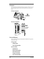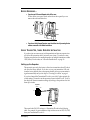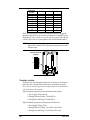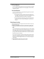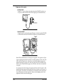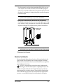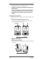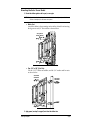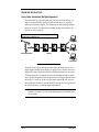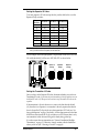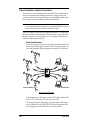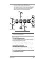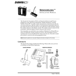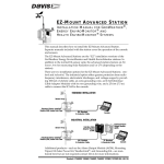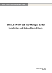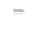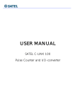
1
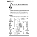
WIRELESS REPEATER
WITH
SOLAR
OR
AC -P O W E R
The Wireless Repeater receives data from a Wireless Weather Station sensor
array and re-transmits it to the console. The repeater serves to extend the
transmission range and improve reception between the sensor array’s transmitter and the console’s receiver.
Each repeater has a transmitting and receiving range of between 100’ to 1500’
(30 to 450 m) depending upon the terrain. The repeater can listen for up to 8
different transmitter signals and can pass those signals on to another repeater
or to any number of receivers.
Note: The Wireless Repeater operates on a low power frequency that does not require an FCC license.
The repeater’s flexibility allows you to put together your weather system in a
number of different ways. The most common setup is to install the repeater in
between a transmitter and a receiver to improve reception. Another possibility
is to install a chain of up to 8 repeaters to carry the transmitter’s signal over a
longer distance, or around obstacles. And a third option is to establish a network of weather stations by linking the chain of repeaters to up to 8 different
wireless stations.
This manual lays out the three different setup options in separate sections
based on how many repeaters and transmitters you plan to install.
✦ The first section, “Single Transmitter, Single Repeater Installation” on page 3,
discusses the most common and simplest installation—that of one transmitter,
one repeater and one or more receivers.
✦ The second section, “Daisy-Chain Installation (Multiple Repeaters)” on page 10,
discusses daisy-chaining up to 8 repeaters in succession to increase the range
between a single transmitter and one or more receivers.
✦ And the third section, “Network Installation (Multiple Transmitters)” on page 12,
discusses setting up a complex network of transmitters, repeaters, and receivers.
These setup instructions apply whether you have a solar-powered or an ACpowered repeater.
Product # 7614 & 7615
C OMPONENTS
The Wireless Repeater includes the following components. Please be sure you
have everything you need for either the AC-powered or the solar-powered
model.
AC-Power Components
#6 x 1" (25 mm long)
Self-Threading Screws
AC Power Adapter
AC-Powered
Repeater
Solar Power Components
1-1/2" U-Bolts
and Saddles
1/4" Flat Washers
1/4" Hex Nuts
1/4" x 1 1/4"
Lag Screws
Shelter
T OOLS
AND
Cable
Tie
M ATERIALS
You may need the following tools and materials for either the AC-powered or
solar-powered model.
AC-Power Model
✦ Phillips Screwdriver
✦ Pencil or Other Pointed Object
Solar Power Model
✦ Adjustable Wrench
✦ Medium Flat Head Screwdriver
✦ Medium Phillips Screwdriver
✦ Compass or Local Area Map
✦ Pencil or Other Pointed Object
Page 2
Wireless Repeater
B EFORE B EGINNING ...
✦ If you have an AC-Powered Repeater, take off the cover.
To take off the cover, press down on the tabs at the top until you can
remove the tabs from their slots.
B
A
Base
Cover
REMOVING THE COVER OF THE AC-POWER REPEATER
✦ If you have a Solar-Powered Repeater, open the shelter door by loosening the two
retainer screws with a flat-bladed screwdriver.
S INGLE T RANSMITTER , S INGLE R EPEATER I NSTALLATION
If you have just one sensor array (with transmitter) and just one repeater, simply follow the instructions below to install your system. If you have a more
complex setup that involves multiple repeaters or multiple transmitters within
1500’ (450 m) of each other, see “Advanced Installations” on page 10.
Setting up the Repeater
The repeater is pre-set by the factory to listen for a transmitter whose ID code is
also set to the factory default. If you have not reset your transmitter’s ID code
from the factory default, then your repeater should pick up your transmitter’s
signal automatically and you can skip to “Choosing a Location” on page 4.
If you have changed the Transmitter ID code to one of the 7 other optional dip
switch settings, you need to set the repeater to listen for that ID code. To do so,
first find your current transmitter settings by looking at the position of its first
three dip switches.
Dip Switches
UNIT ID
TEST
S1
ON
1 2 3 4
RUN
SensorLink
Transmitter
TRANSMITTER DIP SWITCHES
Then match the ON/OFF settings to a Transmitter ID code in the following
table. For example, if your transmitter’s dip switches are set to OFF, ON, OFF,
then your Transmitter ID code is 3.
Before Beginning...
Page 3
TRANSMITTER
ID CODE
DIP SWITCH 1
DIP SWITCH 2
DIP SWITCH 3
#1 (default)
#2
#3
#4
#5
#6
#7
#8
off
off
off
off
ON
ON
ON
ON
off
off
ON
ON
off
off
ON
ON
off
ON
off
ON
off
ON
off
ON
Finally, set your repeater to listen for that transmitter signal by flipping the
appropriate SensorLink Tx dip switch on your repeater. For example, if your
Transmitter ID code is 3, then, use a pencil or some other pointed object to flip SensorLink Tx dip switch #3 on your repeater to ON (see the illustration below).
CAUTION: Use the larger white numbers (1-8) printed on the green board to indicate which dip switch
belongs to which Transmitter ID code. Smaller numbers printed by default on the switch
itself may not agree.
Transmitter Dip Switches
on Repeater
1
2
3
4
5
6
7
8
SENSORLINK TX
ON
S2
ON
1 2 3 4 5 6 7 8
S1
REPEATER DIP SWITCHES TO SELECT TRANSMITTER
Choosing a Location
The range of the radio transmission depends on several factors. Position the
repeater as close to the transmitter and receiver as possible for best results.
Note: Given the maximum ranges below, the repeater may need to be somewhat closer
to the receiver than to the transmitter.
Typical maximum ranges between the transmitter and the repeater:
✦ Line of Sight: 1500 feet (450 m)
✦ Through Walls and Ceilings: 700 feet (225 m)
✦ Through Trees and Foliage: 700 feet (225 m)
Typical maximum ranges between the repeater and the receiver:
✦ Line of Sight: 400 feet (120 m)
✦ Through Walls and Ceilings: 100 to 200 feet (30 to 60 m)
✦ Through Trees and Foliage: 100 to 200 feet (30 to 60 m)
Page 4
Wireless Repeater
AC-Powered Repeaters
Look for a sheltered location with access to an AC-power outlet. For example, you could mount the repeater in a room or garage, or in one of Davis’
weatherproof shelters.
Solar-Powered Repeaters
Look for a location where you can position the solar panel to receive maximum exposure to the sun’s rays:
✦ The solar panel works best when the surface of the panel receives
full sunlight. Mount the panel away from fences, buildings, trees or
other obstructions that may cast shadows over the panel.
✦ The panel should be mounted facing south in the Northern Hemi-
sphere and north in the Southern Hemisphere for maximum sun
exposure.
Testing Proposed Locations
Test your proposed transmitter, repeater and receiver locations to ensure successful data transmission.
1. Make sure your transmitter and receiver are in position and are operating in test
mode.
To place the transmitter in test mode, flip dip switch #4 to “TEST” and then
power it up. To place the receiver in test mode, first apply power to the console and then flip dip switch #4 to the opposite side of wherever it was on
powerup. Refer to the Wireless Weather Station or SensorLink installation
manual for assistance if necessary.
In test mode, the transmitter’s indicator LED will flash to indicate that the
sensor unit is transmitting and the receiver will beep whenever it receives
data from the transmitter (approximately every 2.5 seconds if the signal is
within range).
2. Temporarily place the repeater where you plan to mount it.
Single Transmitter, Single Repeater Installation
Page 5
3. Apply power to the repeater.
✦ AC-Power Model
Plug the AC-power adapter into the jack marked POWER, and into an
AC-power outlet.Watch for the LEDs to light up (as described below).
Repeater
AC Power Adapter
APPLYING POWER TO THE AC-POWERED REPEATER
✦ Solar-Power Model
Plug the power cord from the gel cell battery to the jack marked POWER
as shown below Watch for the LEDs to light up, (as described below).
Repeater
Rechargeable
Gel Cell Battery
Power
Plug
APPLYING POWER TO THE SOLAR-POWERED REPEATER
Both LEDs should flash once when power is applied. The repeater will perform a self-diagnostic that lasts about 7 seconds and then, if all is well, both
LEDs will flash again twice. After that second double-flash, the repeater
begins listening for a signal. If it finds one, the lower LED will flash as the
data is received and then the upper one will flash as the data is transmitted
out again.
If, one minute after the bootup, the repeater still cannot find a signal, it will
double-flash three times and then shut itself down in order to save power. If
this happens, check that your transmitter is transmitting and try repositioning your repeater for better reception. Remove and reapply power to the
repeater to make it listen for the signal.
Page 6
Wireless Repeater
Once the repeater is receiving and re-transmitting reliably, check your console’s reception. In test mode, the console/receiver should beep approximately every 2.5 seconds to indicate that a data packet has been received. If
the console is not beeping or is beeping infrequently, reposition the repeater
for better reception.
Note: If necessary to overcome difficult terrain or excessive obstructions, you can add additional
repeaters to boost the signal through—or carry it around—various obstacles.
4. When you find a location that works, switch all three units out of test mode.
To switch the transmitter and receiver out of test mode, flip dip switch #4 on
both. Similarly, to switch the repeater out of test mode, flip the Repeater ID
dip switch #4 from the TEST position to the off position as shown below.
Repeater ID Code
Dip Switches
REPEATER ID
ON
1 2 3 4
TEST
REPEATER DIP SWITCH SET TO TEST MODE OFF
Note: Leaving the repeater in test mode will cause the LEDs to flash unnecessarily and thus drain
additional power from your power supply. You should use the test mode only when necessary.
5. Remove power from the repeater.
M OUNTING
THE
R EPEATER
Once you determine that your chosen locations will transmit and receive the
signal, continue with the installation by mounting the repeater. Mounting
hardware has been included for the most common installations (see figures on
pages 8 and 9 for instructions).
CAUTION: Any metal object can and may attract a lightning strike,
including any outside-mounted repeater. If lightning strikes your unit
or strikes somewhere nearby, the unit’s internal electronics may suffer anywhere between little to extensive damage. The unit itself has been designed
with considerable surge protection, but to safeguard nearby equipment and
structures, we recommend following local recommendations on properly
Mounting the Repeater
Page 7
grounding your installation. For more information, contact your local lightning
protection authority and/or refer to the following articles:
✦ MIL-HDBK-419A: Grounding, Bonding, and Shielding for Electronic Equipments and
Facilities, 29 Dec 1987.
✦ National Fire Protection Association, 1997: Standard for Installation of Lightning Pro-
tection Systems, 1997 ANSI/NFPA 780, National Fire Protection Association, Quincy, MA.
✦ NEC, National Electrical Code, 1996 Edition: National Fire Protection Information,
Quincy, MA.
Mounting the AC-Power Model
Install the repeater in an attic or garage, or in one of Davis’s weatherproof shelters.
1. Attach the base to the mounting surface using the #6 x 1” screws.
Use two screws (as pictured below) when attaching to a stud. Use three
screws (as pictured below) in any other case.
#6 x 1" Screws
Use two screws if attaching
to a stud.
Use three screws if attaching
anywhere else.
MOUNTING THE BASE OF THE AC-POWERED REPEATER
2. Apply power (see step 3 on page 6).
3. Reattach the repeater cover to the base.
Make sure the tabs on top of the cover snap back into their slots, locking the
cover in place.
A
B
REATTACHING THE AC-POWERED REPEATER COVER
Page 8
Wireless Repeater
Mounting the Solar Power Model
1. Mount the shelter against a wall or post, or on a pipe.
CAUTION: Remember to face the solar panel south in the Northern Hemisphere (or north in the
Southern Hemisphere) for maximum sun exposure.
✦ Wall or Post
Attach the shelter to the mounting surface in the desired location using
the lag screws and 1/4" flat washers as shown below.
1/4" Lag Screws
and 5/16" Washers
MOUNTING SOLAR-POWERED REPEATER ON A WALL OR POST
✦ Pipe - 3/4” to 1 1/4” (19 to 31 m)
Use the 1-1/2" U-Bolts and saddles, and the 1/4" washers and hex nuts
as shown below.
1/4" Hex Nuts
and Washers
1-1/2" U-Bolts
and Saddles
MOUNTING POWER KIT ON A SMALL PIPE
2. Apply power (see step 3 on page 6) and close the shelter door.
Mounting the Repeater
Page 9
A DVANCED I NSTALLATIONS
Daisy-Chain Installation (Multiple Repeaters)
To transmit data up to one and a half miles (two and a half kilometers), or to
improve reception in hilly, heavily-wooded or urban areas, you can daisychain up to 8 repeaters together. For instructions on daisy-chaining multiple
repeaters, see below; for instructions on adding multiple transmitters to the
network as well, see page 12.
A Transmitter with ID Code #1 sends data (through a daisy-chain of Repeaters)
to Receivers with ID Codes also set to #1.
1
1
A
1
B
1
C
1
D
1
1
Sensor Array/Transmitter
1
1
1
Repeaters
1
Console/Receiver
DAISY-CHAIN INSTALLATION - MULTIPLE REPEATERS
To install a chain of more than one repeater, follow the instructions as if for a
single repeater installation but, before you apply power to test the system, set
Repeater ID codes so that each will listen to the repeater before it in succession.
The first repeater (i.e., the repeater closest to the transmitter) needs no adjustment. The second repeater, however, needs to be set to Repeater ID code B; and
the third, to C; and so on. In this way, the second repeater (B) will only tune
into signals from the first (A), and the third (C) will only tune into signals from
the second (B), and so on, thereby improving reception.
Note: The repeater “closest to the transmitter” means the repeater with the best connection to that
transmitter (i.e., whether or not it is the shortest distance away may be less important than a
clear line of sight).
Page 10
Wireless Repeater
Setting the Repeater ID Codes
To set each repeater’s ID code (except the first), use the table below to set the
Repeater ID dip switches:
REPEATER
ID CODE
DIP SWITCH 1
DIP SWITCH 2
DIP SWITCH 3
A (default)
B
C
D
E
F
G
H
off
off
off
off
ON
ON
ON
ON
off
off
ON
ON
off
off
ON
ON
off
ON
off
ON
off
ON
off
ON
Note: If you have only one repeater, you do NOT need to set any Repeater ID code dip switches. However, if you have more than one repeater, use the above chart.
So, for example, the second (B) repeater’s dip switches will be set to OFF, OFF,
ON, while the third (C) will be set to OFF, ON, OFF, as shown below.
Repeater A
Settings
Repeater B
Settings
REPEATER ID
ON
TEST
1 2 3 4
REPEATER ID
ON
1 2 3 4
REPEATER ID
ON
1 2 3 4
TEST
Repeater C
Settings
TEST
DIP SWITCHES ON REPEATERS A, B, AND C
Setting the Transmitter ID Codes
Once you have set the Repeater ID codes, determine whether you need to set
Transmitter ID codes. If you have only one transmitter and its dip switches are set to
the default ID code (#1), then you do not need to set any Transmitter ID codes on the
repeaters.
If the transmitter’s dip switches are set to some code other than the default
(#1), then the closest repeater to a transmitter is the only repeater that should
have its SensorLink Tx dip switch set to that transmitter’s ID Code (see “Setting up the Repeater” on page 3 for details). All the other repeaters in the chain
should have their SensorLink Tx dip switches set to OFF because there is only
one transmitter in this chain and its signal is already being picked up.
If you have more than one transmitter, see “Network Installation (Multiple
Transmitters)” on page 12. Otherwise, simply continue with the installation
where you left off (see “Choosing a Location” on page 4).
Advanced Installations
Page 11
Network Installation (Multiple Transmitters)
If you have two or more transmitters in your network, follow the instructions
as if for a multiple repeater installation but, before you apply power to test
your chosen locations, set unique ID codes for each transmitter and then set the
closest repeater to each transmitter to listen to that transmitter.
Note: Each transmitter in your network must have a different ID code so that its signal remains distinct and identifiable throughout the network. See your Wireless Weather Station or SensorLink
manual for instructions on how to set Transmitter and Receiver ID Codes.
There are a number of ways you can configure your network. The only rule is
that each transmitter’s data should only enter the network at one point, that is,
through one repeater. Or, said another way, no two repeaters should be set to
listen to the same transmitter directly.
✦ Multiple Transmitter Network
You can set one repeater to listen to up to eight transmitters directly, and
then re-transmit those signals to your consoles. To set the repeater to listen to each transmitter, flip the appropriate SensorLink Tx dip switches.
1
1
1
2
2
1
2
A
3
2
3
4
4
Repeater
3
3
4
Sensor Array/Transmitter
Console/Receiver
4
MULTIPLE TRANSMITTER NETWORK
In the diagram above, the Repeater’s SensorLink Tx dip switches would
have #1, #2, #3, and #4 set to ON, and the rest set to OFF.
The Repeater’s ID Code dip switches, on the other hand, would simply
be set to default ID Code A (OFF, OFF OFF) because the repeater in the
above diagram does not need to listen to any other repeaters.
Page 12
Wireless Repeater
✦ Combo Network - Multiple Transmitters AND Multiple Repeaters
Any combination of the multiple transmitter network on page 12 and the
daisy-chain network on page 10. Notice in this example how the data all
flows in one direction; it enters the network at a point somewhere
upstream and exits the network somewhere downstream.
3
3
A
1
3
3
B
1
3
C
1
1
2
1
2
Repeaters
3
D
4
1
1
4
2
4
4
Console/Receiver
2
2
Sensor Array/Transmitter
4
COMBO NETWORK- MULTIPLE TRANSMITTERS AND MULTIPLE REPEATERS
Note: No matter how closely they are spaced, no two repeaters should be listening to the same transmitter directly–this only generates interference.
Setting up a Network
1. Set ID codes for each transmitter and receiver.
See your Wireless Weather Station or SensorLink manual for instructions on
how to set transmitter and receiver ID Codes.
2. Choose locations for the farthest transmitter, its repeater and its receiver.
Set the repeater to listen for that transmitter’s signal (see “Setting up the
Repeater” on page 3 for details). Make sure the repeater is receiving and
then re-transmitting the signal properly.
3. Add any additional repeaters as necessary, one at a time.
Make sure you set each one’s Repeater ID code (see “Setting the Repeater ID
Codes” on page 11 for details).
4. Put all the units in test mode to test the transmission of the data from the transmitter, through each repeater, to the receiver.
Advanced Installations
Page 13
5. Turn off the “farthest” transmitter and then add the second farthest transmitter (and
its receiver) to your network. Check the reception of that second signal at each point.
The goal is to make sure that your network is functioning properly at every
stage so that if, at some point, you add a transmitter, repeater, or receiver
that is either malfunctioning or poorly positioned, you will know immediately.
6. Add additional transmitter/receiver pairs one at a time, making sure to test only one
signal (i.e., one pair) at a time.
7. Once each transmitter/receiver pair has been tested by itself, add signals (i.e., the
transmitters you tested above) slowly to the network.
If a repeater is set to listen for more than one signal, the repeater will wait
until it has acquired all the signals you have told it to listen for before it
begins repeating. If it fails to acquire one or more of the signals after one
minute, the repeater will begin repeating the signals it has found and will
check again for the missing signals once every hour.
Note: If the repeater fails to acquire any signals at all, it will time out after one minute. In this
case, you should reposition the repeater, check that its dip switches are set correctly and
that the transmitter/repeater it is listening for is functioning properly, and then power the
repeater up again.
Either way, whether repeater acquires all the signals or it does not, the LEDs
will flash three times. Then, for each successful transmission of a signal, the
lower LED will flash followed by the upper LED. Count the number of distinct pairs (of flashes) to determine if any signals are missing.
8. Take all the units out of test mode.
Leaving the transmitters, repeaters, or receivers in test mode drains unnecessary power from your power supply.
Page 14
Wireless Repeater
T ROUBLESHOOTING
Please check the troubleshooters listed below if you experience a problem with
your unit. Then, if you still are unable to solve the problem, we encourage you
to call Technical Support at (510) 732-7814 for assistance (Mon-Fri, 7am-5:30pm
PST). Please do not return your unit for repair without prior authorization.
✦ The LEDs do not flash on powerup.
Make sure that your power cord connections are secure. If your unit is ACpowered, try plugging the repeater into another outlet and some other
(functioning) device into the outlet you are using.
If your unit is solar-powered and the gel cell battery is over 5 years old, try
replacing the battery. (Do not incinerate the used battery, it may burst.
Arrange for proper recycling in your locality.)
If your unit is solar-powered and the battery is less than 5 years old, make
sure the panel is not being shaded by the sun. Open the shelter and check
that the wire connections are secure and that the battery is free from corrosion and excessive deposits on the terminals. Clean the solar panel using a
water spray, or a soft cloth and soapy water followed by a clean water rinse.
Check the battery’s voltage with a voltmeter; the battery must have at least
3.8 V to power the station. (More than 4 V indicates and adequatelycharged battery.) Try exposing the panel to ample sunlight for a week, or use
a charger designed to recharge a 4 V gel cell battery.
✦ The LEDs do not flash twice after the self-diagnostic.
If you consistently get the first flash upon powerup but no double-flash
7 seconds later, something is wrong with the unit’s circuitry. Please contact
Technical Support for assistance (see above).
✦ The lower LED is not lighting up, but the upper one is.
When the repeater fails to receive a valid data packet, it still sends out a "no
data" packet to keep downstream repeaters in sync. Therefore, even if no
data packet is received, the lower receive LED will not light but the upper
transmit LED will. This is useful in a network situation because it can show
where the last good packet was received in a chain of repeaters.
If the lower LED is consistently failing to light up, make sure the transmitter
(or repeater) that it is listening to is powered up and functioning correctly.
You can also try moving the repeater closer to the transmitter (or prior
repeater) or for better reception.
Troubleshooting
Page 15
S PECIFICATIONS
Transmit frequency: 916.5 MHz
ID codes: 8 user-selectable
License: Low power (less than 1 mW), no license required
Temperature range: -40 to 60 °C
Power Input: 4 to 12 VDC output @ 1.5 mA
FCC P ART 15 C LASS B R EGISTRATION W ARNING
This equipment has been tested and found to comply with the limits for a class
B digital device, pursuant to Part 15 of the FCC Rules. These limits are
designed to provide reasonable protection against harmful interference in a
residential installation. This equipment generates, uses and can radiate radio
frequency energy and, if not installed and used in accordance with the instructions, may cause harmful interference to radio communications. However,
there is no guarantee that interference will not occur in a particular installation.
If this equipment does cause harmful interference to radio or television reception, which can be determined by turning the equipment off and on, the user is
encouraged to try to correct the interference by one or more of the following
measures:
✦ Reorient or relocate the receiving antenna.
✦ Increase the separation between the equipment and receiver.
✦ Connect the equipment into an outlet on a circuit different from that to which the
receiver is connected.
✦ Consult the dealer or an experienced radio/TV technician for help.
Shielded cables and I/O cords must be used for this equipment to comply
with the relevant FCC regulations. Changes or modifications not expressly
approved in writing by Davis Instruments may void the user's authority to
operate this equipment.
Product Numbers: 7614 & 7615
Davis Instruments Part Number: 7395-105
Wireless Repeater with Solar or AC-Power
Rev. A Manual (7/8/99)
Controlled Online: Weather Manuals:Accessories:Wireless Repeater
This product complies with the essential protection requirements of the EC EMC Directive 89/336/EC.
© 1999 Davis Instruments Corp. All rights reserved.
3465 Diablo Avenue, Hayward, CA 94545-2778
510-732-9229 • Fax: 510-732-9118
E-mail: [email protected] • www.davisnet.com