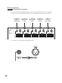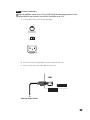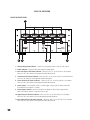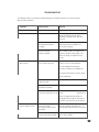
1
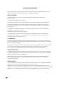
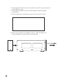
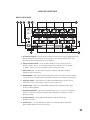
®
Signature MPA 5150
Monster Home Theater Music
Five Channel Reference Power Amplifier
Owner’s Manual
TABLE OF CONTENTS
Page
Important Safety Instructions . . . . . . . . . . . . . . . . . . . . . . . . . . . . . . . . . . . . . . . . . . . . . . . . . . . . . . . . . . . . . . . .i
Introduction . . . . . . . . . . . . . . . . . . . . . . . . . . . . . . . . . . . . . . . . . . . . . . . . . . . . . . . . . . . . . . . . . . . . . . . . . . . . 1
Overview . . . . . . . . . . . . . . . . . . . . . . . . . . . . . . . . . . . . . . . . . . . . . . . . . . . . . . . . . . . . . . . . . . . . . . . . . . . . . . 4
Installation Guidelines . . . . . . . . . . . . . . . . . . . . . . . . . . . . . . . . . . . . . . . . . . . . . . . . . . . . . . . . . . . . . . . . . . . . 5
Connection Guide . . . . . . . . . . . . . . . . . . . . . . . . . . . . . . . . . . . . . . . . . . . . . . . . . . . . . . . . . . . . . . . . . . . . . . . 8
MPA5150 Connections. . . . . . . . . . . . . . . . . . . . . . . . . . . . . . . . . . . . . . . . . . . . . . . . . . . . . . . . . . . . . . . . . . . . 10
MPA5150 Operation . . . . . . . . . . . . . . . . . . . . . . . . . . . . . . . . . . . . . . . . . . . . . . . . . . . . . . . . . . . . . . . . . . . . . 25
Troubleshooting . . . . . . . . . . . . . . . . . . . . . . . . . . . . . . . . . . . . . . . . . . . . . . . . . . . . . . . . . . . . . . . . . . . . . . . . . 26
Specifications . . . . . . . . . . . . . . . . . . . . . . . . . . . . . . . . . . . . . . . . . . . . . . . . . . . . . . . . . . . . . . . . . . . . . . . . . . . 27
Appendix A – System Connection Diagram . . . . . . . . . . . . . . . . . . . . . . . . . . . . . . . . . . . . . . . . . . . . . . . . . . . . . 38
Appendix B – Amplifier Dimensions . . . . . . . . . . . . . . . . . . . . . . . . . . . . . . . . . . . . . . . . . . . . . . . . . . . . . . . . . . 39
IMPORTANT SAFETY INSTRUCTIONS
Please read and observe the following safety points at all times:
i
•
Read these instructions.
•
Keep these instructions.
•
Heed all warnings.
•
Follow all instructions.
•
Do not use this apparatus near water.
•
Clean only with dry cloth.
•
Do not block any ventilation openings. Install in accordance with the manufacturer’s instructions.
•
Do not install near any heat sources such as radiators, heat registers, stoves or other apparatus
(including amplifiers) that product heat.
•
Do not defeat the safety purpose of the polarized or grounding-type plug. A polarized plug has two
blades with one wider than the other. A grounding-type plug has two blades and a third grounding
prong. The wide blade or the third prong are provided for your safety. This plug is designed to be
inserted into a grounded outlet only. If the provided plug does not fit into your outlet, consult an
electrician for replacement of the obsolete outlet.
•
Protect the power cord from being walked on or pinched particularly at plugs, convenience receptacles
and the point where they exit from the apparatus. Since the power cord is the method of connection
and disconnection to AC mains supply, it must remain readily operable to provide a means of
disconnection.
•
Only use attachments/accessories specified by the manufacturer.
•
Unplug this apparatus from its power source during lightning storms or when unused for long periods
of time.
•
Refer all servicing to qualified service personnel. Servicing is required when the apparatus has been
damaged in any way, such as power-supply cord or plug is damaged, liquid has been spilled or objects
have fallen into the apparatus, the apparatus has been exposed to rain or moisture, does not operate
normally, or has been dropped.
•
To reduce the risk of fire or electric shock, do not expose this apparatus to rain or moisture
Additional Manufacturer Warnings
WARNING – Power Sources
DO NOT plug this apparatus into a power outlet that differs from the source indicated for safe use. If you don’t know
the type of electrical power that is supplied to your home, please consult your local power company.
WARNING – Cord Safety
A. Protect the power cord from being walked on or pinched particularly at plugs, convenience receptacles and the
point where they exit from the apparatus. When routing your Monster Reference Home Theater Music Power Amplifier
AC power cord, do not place it near heavy foot traffic areas (e.g., hallways, doorways, and kitchen floors).
Do not create a trip hazard with the power cord.
B. Since the power cord is the method of connection and disconnection to AC mains supply, it must remain
readily operable to provide a means of disconnection.
C. Only use attachments/accessories specified by the manufacturer.
WARNING – Grounding and Polarization
Your Monster Home Theater Music Reference Power Amplifier has a three-wire grounding-type AC plug (a three-prong
outlet). This plug is designed to be inserted into a grounded outlet only.
A. A. If this plug doesn’t fit your outlet, DO NOT attempt to force it.
B. B. DO NOT attempt to defeat the grounding feature by using a 3-to-2 prong adapter. Instead, call a local electrician
to install a properly grounded outlet.
C. B. DO NOT attempt to defeat the grounding feature by using a 3-to-2 prong adapter. Instead, call a local electrician
to install a properly grounded outlet.
WARNING – Avoiding Electrical Shocks
A. To reduce the risk of fire or electric shock, do not expose this apparatus to rain or moisture. Do not operate near
rain or water that’s spilled or openly exposed (e.g., bathtub, kitchen or bathroom sink).
B. Do not operate your Monster Reference Home Theater Music Power Amplifier if liquid of any kind is spilled
onto or inside the unit.
WARNING – Exposure To Heat
Do not block any ventilation openings. Install in accordance with the manufacturer’s instructions.
Do not install near any heat sources such as radiators, heat registers, stoves or other apparatus (including amplifiers)
that product heat. Do not expose your Monster Home Theater Music Reference Power Amplifier to direct sunlight or
place it near wall heaters, space heaters, or any enclosed space prone to temperature increase. Please see the section
on installation for more information.
If, for any reason, your Monster Home Theater Music Reference Power Amplifier is not operating
properly, do not remove any part of the unit for repair. Unplug it and consult this owner’s manual
for warranty and service information.
ii
INTRODUCTION
Dear Enthusiast:
Thank you for purchasing my Signature Series Monster Home Theater Music Reference Power
Amplifier. I started my Signature Series in 2002 by introducing special versions of the Monster
Power Automatic Voltage Stabilizer 2000, Home Theater Power Source 7000 and Reference
Home Theater PowerCenter 5100. Each of these products represented a breakthrough in
performance and affordability and included special enhancements for audiophiles and videophiles
who appreciate minute attention to detail and elegant design…all geared towards getting
the most from their home theater system.
Now I am introducing my signature line of Monster Reference Home Theater Music Power Amplifiers for those
of you who are passionate about movies and music. I’ve spent years perfecting this design working with renowned
audiophile designers Richard Marsh, Demian Martin and the other dedicated professionals at Monster. After countless
hours of critical listening and dozens of prototype designs, we have finally completed an amplifier that is good
enough to be part of The Head Monster’s Signature Series.
The Home Theater Music amplifiers are designed to please the most demanding critical listeners…like me! I like
to listen to music LOUD with all the complex harmonics and dynamic range reproduced as accurately as possible.
I also like to watch movies and to have the power and responsiveness necessary to reproduce movie soundtracks
from the subtlest rustle of leaves to the most violent explosions. It takes a very special amplifier design to satisfy
the needs of both home theater and music.
I hope you enjoy your favorite music and movies even more with your new Monster home theater music amps.
Monsterously,
Noel Lee
The Head Monster
P.S. Here are some of the unique features of the Monster Home Theater Music Reference Power Amplifiers:
MONSTER MIRRORED AMPLIFIER TECHNOLOGY™— (MMAT™)
The MPA 5150 five channel amplifier uses a current-feedback topology we call MMAT™ to ensure low distortion and greater
clarity even at the highest playback levels. Any signal put into this amp will be mirrored at the output, just amplified, with all
details intact. Monster amplifiers employ fully complimentary differential circuits, so the two halves of the amplifier are mirror
images of themselves — helping lower noise and distortion.
OTHER CIRCUIT INNOVATIONS
At the input end, a balanced complimentary push-pull stage delivers ultra-wide bandwidth performance for
the best reproduction of today’s ultra high resolution 192khz DVD-Audio and Super Audio CD formats. Monster
amplifiers are specially designed to be stable at high frequencies to support DVD-A and SACD.
At the output end, high current MOSFET output transistors deliver instantaneous current for maximum transient impact.
Monster amps provide high current peak delivery for a realistic, exciting home theater and music experience.
1
SEPARATE POWER SUPPLIES
A unique feature of Monster amplifiers, which allow them to outperform any receiver, is that each channel has its own power
supply. Receivers that share a single power supply across all channels will actually deliver far lower power levels than the
maximum power rating when all channels are driven. Monster amps won’t sag when the power demands are high because
they are designed to support the current delivery for each channel independently. Monster home theater music reference
power amps deliver detail, clarity, dimensionality and low distortion audio with powerful bass at virtually any power level.
LOADS OF POWER
The MPA 5150 delivers 250 continuous watts per channel into 4 ohms with all channels driven (150 watts/channel into 8
ohms). Instantaneous peak power exceeds 300 watts into 4 ohms (200 watts/channel into 8 ohms).
LABORATORY-GRADE DIGITAL POWER METERS
Watch how the power meters jump around with your favorite dynamic music passage or explosive movie scene, and which
channels require the most power. That will tell you how much power the amps are delivering and what is required
by the material you are listening to. You’ll be surprised to see how much power some music and movie transients need
to sound as powerful as the composer or director had in mind for the original experience.
Watch the meters as the amplifiers pump out big, powerful, but tightly controlled bass. The separate transformer and power
supply on each channel is the key. Big room-energizing bass, properly recreated, gives the sound a sense of space. Give
yourself a good view of the meters really jumping with power by playing Telarc International’s recording of Tchakowski’s 1812
Overture with Erich Kunzel and the Cincinnati Pops. Just after 14 minutes into the recording, listen to the cannon shots and
watch the amp meters show just how much sheer power is required to accurately reproduce one of the biggest
and most breathtaking transients in recording history.
THE MONSTER BACKBONE
Monster recently introduced a new way of looking at a total home theater music experience. It all starts with the “polluted”
AC power from your wall. Power line noise, spikes, sags, noise from your own components, noise generated from other
devices on the same electrical circuit as your system — all of these are detrimental to the audio experience. To achieve
the best home theater and music listening experience, you must take steps to ensure that the power delivery to all
of your home theater music components is stable and clean.
You can realize a truly amazing home theater music experience if you ensure that the power being delivered to all
of your audio and video components is at a stable voltage and filtered from power line noise. Just as the home theater music
amplifiers are designed to provide all the power (wattage) that is demanded from movies and music, Monster recommends
providing all of the clean and stabilized power (voltage and current) that is needed by your electronics to get all
the performance they were designed to deliver.
Voltage stabilization can be achieved by adding a Monster Power Automatic Voltage Stabilizer to your system (AVS 2000).
“Polluted” power can be cleaned by adding a Monster Power Reference Home Theater PowerSource (HTPS 7000) which
will also isolate your components and protect them from electrical spikes and surges.
By addressing the needs of power quality (stabilized, clean power) and power capacity (powerful amplification) from
your electronics, you can build the backbone for a truly amazing home theater music experience.
2
THE DESIGN MINDS BEHIND THE MONSTER HOME THEATER MUSIC
REFERENCE POWER AMPLIFIERS
Richard Marsh – There are few experts able to solve the complex problems of AC power.
Richard Marsh is one of the illustrious few. He has designed best selling power conditioning
components costing more than $3,000 and now brings his expertise to Monster Power.
Richard developed Monster’s exclusive Clean Power ™ circuitry. He is also responsible
for several other groundbreaking designs. Richard’s background and research into amplifier
and capacitor design led to his development of the Servo-DC feedback concept in power
amplifiers – a concept that is used by virtually every amplifier manufacturer today.
His status as both the inventor of the MultiCap™ internal bypass capacitor and as the driving
force behind the high-end audio balanced circuit design concept has influenced the audiophile
community for years. Richard is responsible for some of the high end audio world’s most
respected product designs, essays and articles, and has contributed to Fi, The Absolute Sound
and Audio magazines. He is included in Who’s Who in the West.
Noel Lee – Noel Lee is best known for popularizing the concept of high performance audio
cable over 20 years ago with his creation of Monster Cable. Originally a laser-fusion design
engineer at Lawrence Livermore National Laboratory and later a touring musician, Noel has
invented or co-invented over 125 U.S. and international patents and drives the explosive growth
of The Monster Group into more than 80 countries worldwide. Monster Power is his realization
of a long-nurtured vision of making affordable power solutions that deliver the best possible
sound and picture.
3
OVERVIEW
The following information will guide you through the setup and operation of the MPA 5150 Monster Home Theater Music
Reference Amplifier. For full Home Theater Music enjoyment please read this entire manual before setup.
BEFORE YOU BEGIN
Please make sure you have the following to best enjoy the high performance of your Monster Home Theater Music
Reference Power Amplifier.
A. This owner’s manual.
B. Your favorite pen or a computer with an Internet browser (for registering your warranty information).
C. One or more Monster Home Theater Music Reference Power Amplifiers.
D. Your source equipment, speakers and their owners manuals.
E. Monster Cable interconnects and Monster Cable speaker cable to connect source components and speakers
to your Monster Reference Home Theater Music Power Amplifier(s).
CABLES NEEDED TO CONNECT 5 CHANNELS OF AMPLIFICATION
A. 5 individual Monster Cable, M-Series, Z-Series or Sigma Audio Interconnects – length determined by your system
rack. Connector type determined by your receiver/preamp.
B. 5 runs of Monster Speaker Cable – length determined by the size of your room and speaker placement.
If your Receiver/Preamp has a remote trigger out:
A. 2 runs of 1/8”-to-1/8” mono mini cable included with the amplifier.
If your receiver does not have a remote trigger out:
B. 1 run of 1/8”-to-1/8” mono mini cable and a 3-30v power transformer included with the amplifier.
UNPACKING THE AMPLIFIERS
Take care in unpacking your new Monster amplifier so as not to scratch or damage the unit. Monster recommends
saving the box should you ever need to move it or return it for any reason.
While unpacking please make note of the enclosed items and set them aside.
Items Included
1 Ea
Copy of this Manual
1 Ea
1/8”-to-1/8” mono mini remote trigger cable
1 Ea
DC Power Transformer to be used as a remote trigger if needed
1 Pr
Front Rack Mounting Ears
1 Pr
Rear Rack Mounting Bracket
1 Set
Screws for Rear Rack Brackets
1 Ea
PL 400 IEC - type AC Power Cord
4
INSTALLATION GUIDELINES
Before placing, connecting and using your new Monster Home Theater Music Reference amplifier, please read
through these guidelines to familiarize yourself with the installation specifications.
HEAT DISSIPATION
The Monster Amp is a high current design, and like all amplifiers, will produce heat under normal
operating conditions.
To maintain proper operation of your amplifiers:
DO NOT stack your amplifiers in an enclosed environment such as closets or completely enclosed audio racks.
When placing your amplifier into your audio system allow 3” of clearance on the top and 2” of clearance
on each side to help disperse the heat. Each amplifier should be placed on a separate shelf with space above
and to the sides.
If the amplifiers are required to be mounted in an enclosed environment, the use of a fan is recommended
to remove excess heat from the enclosure.
DO NOT place amplifiers directly on carpeted floors.
An amplifier placed on carpeting restricts the flow of air from the bottom and causes the amplifier to heat
up prematurely. This may also pose a safety hazard because the carpeting may come in direct contact with
the amplifier’s chassis which is a source of heat.
AC POWER LINE
The Monster Amplifiers are designed to operate from a 120V 60Hz AC power line. Connection is made through
a heavy duty grounded power cord. For safety and proper operation DO NOT remove the ground pin, cut the power
cord or use a ground lifting adapter.
For proper operation and the best possible sound, Monster recommends using a Monster Power Reference Home
Theater PowerCenter to deliver clean AC power to protect your Monster Amplifiers from surges and spikes
on the AC power line. Consult your Monster dealer for information or visit www.monsterpower.com.
AUDIO CONNECTIONS
The Monster Amplifiers are designed to operate from a 110V 60Hz AC power line. Connection is made through a
heavy-duty grounded power cord. For safety and proper operation DO NOT remove the ground pin, cut the power
cord or use a ground lifting, 3-to-2 prong adapter.
Speaker cables for the Front Left, Center and Front Right should be of equal length to maintain best delivery
of sound. The Rear Right and Rear Left should also be of equal length even if the cables runs allow one
to be shorted then the other.
OUTPUT METERS
One the major features of the Monster Home Theater Music Reference Amplifiers are the laboratory-grade digital
meters. The meters show the current output of the channel indicated in watts.
Additional info inserted here regarding true power meters. Ipsum lorum mumar kadaffi boom chuck a luck a
insegrevious orson. Ipsum lorum mumar kadaffi boom chuck a luck a insegrevious orson. Ipsum lorum mumar kadaffi
boom chuck a luck a insegrevious orson. Ipsum lorum mumar kadaffi boom chuck a luck a insegrevious orson.
5
RACK MOUNTING
Your new Monster power amplifier comes with front and rear rack mounting for installing in equipment
racks. The front rack ears are separate from the unit and must be installed prior to rack mounting.
Please follow these instructions to mount your monster amplifier into a rack.
1. Remove the 10 Allen screws that secure the outer trim plates of the amplifier
and set them aside. To avoid scratching the rack ears or face plate, take care when
removing the Allen screws.
LEFT REAR CHANNEL
POWER ON
LEFT CHANNEL
POWER ON
CENTER CHANNEL
POWER ON
RIGHT CHANNEL
POWER ON
RIGHT REAR CHANNEL
POWER ON
LEFT REAR CHANNEL
FULL VOLUME
LEFT CHANNEL
FULL VOLUME
CENTER CHANNEL
FULL VOLUME
RIGHT CHANNEL
FULL VOLUME
RIGHT REAR CHANNEL
FULL VOLUME
LEFT REAR CHANNEL
GAIN
LEFT CHANNEL
GAIN
CENTER CHANNEL
GAIN
RIGHT CHANNEL
GAIN
RIGHT REAR CHANNEL
GAIN
DISPLAY
BRIGHTNESS
MPA5150 SS
POWER ON/OFF
MONSTER HOME THEATRE MUSIC
FIVE CHANNEL REFERENCE POWER AMPLIFIER
2. Attach the rack ears by placing them along side each side of the amplifier. There is a small
metal strip on the back of each rack ear that will fit flush with the side of the amplifier.
6
3. Carefully replace the 5 Allen screws on each side. Make sure that the screws are tight, but do
not over tighten the screws.
4. Carefully place the amplifier into the rack. Hold the amplifier in position and tighten
the front screws.
5. Adjust the depth of the rear rack bracket to match the rails at the back of the rack.
6. Attach the rear rack brackets to the amplifier. Continue to support the amplifier until
the rear rack brackets are secured to both the unit and the rack.
7
CONNECTION GUIDE
The following section will guide you through the steps required to connect your Monster Power Amplifiers to the rest
of your system. Read through this section carefully before connecting.
This section has been broken into steps for each amplifier. For a complete system diagram see Appendix A.
INPUT CONNECTIONS
A. The Signature Monster Amplifiers provide both unbalanced (RCA) type and balanced (XLR) type connections
for use with a variety of systems. Should your Receiver/preamp Processor have both types of connections,
Monster recommends using balanced connections for cleaner more accurate sonic reproduction. Please refer
to your Receiver/preamp Processor owners manual for the available connection types.
Unbalanced RCA Input
Balanced XLR Input
CAUTION: Never connect both balanced and unbalanced to the same input.
Damage to components may occur.
For unbalanced RCA type connections please follow Step 1A for each amplifier.
For balanced XLR type connections, please follow Step 1B for each amplifier.
B. Input connections are marked with the channel name they are intended for. In addition to naming them,
the inputs are marked by color in the following manner.
RED
Right Channel
GREEN
Center Channel
BLUE
Left Channel
8
SPEAKER CONNECTIONS
Just like the inputs, speaker connections are labeled with the channel name as well as being color coded.
CAUTION: : When connecting speakers all polarity markings must be followed
exactly or damage can occur to components.
RED
Positive +
BLACK
Negative -
Never make audio connections when power is applied to the amplifiers or any
other component.
To prevent damage to the Monster Amplifiers and other components, never make connections when power
is applied. Connect amplifiers to AC power last to ensure damage will not occur.
TRIGGER CONNECTIONS
The Monster Home Theater Music Reference Power Amplifiers feature remote trigger input and output to turn
the amplifier on/off with the receiver/preamp. These connections use a 1/8”-to-1/8” mono mini cable included
with the amplifier. For a receiver/preamp that does not have a remote trigger out, a power transformer is included
with the amplifiers as well. Refer to the amplifier specifications page for more information.
The remote trigger works on 3-30v AC/DC and the remote trigger out is 12V DC.
KNOWING THE CONNECTIONS
Before continuing with the connection of the Monster Power Amplifiers, please familiarize yourself with
the amplifier back panel. This will allow you to make the proper connections, prevent damage and ensure
you get the most enjoyment from your amplifiers.
Once you are familiar with the back panels follow the steps provided in the connection guide in order.
9
AMPLIFIER CONNECTIONS
MPA 5150 REAR PANEL
2
3
4
IN
5
6
AC/DC 3-30V
REMOTE TURN ON/OFF
BALANCED
INPUT 2
(RIGHT)
UNBALANCED
INPUT 3
(CENTER)
BALANCED
INPUT 3
(CENTER)
UNBALANCED
INPUT 1
(LEFT)
BALANCED
INPUT 1
(LEFT)
CHANNEL 1 LEFT
CHANNEL 3 CENTER
UNBALANCED
INPUT 2
(RIGHT)
OUTPUT FUSE (RIGHT REAR)
7A 125V SLOW
OUTPUT FUSE (RIGHT)
7A 125V SLOW
OUTPUT FUSE (CENTER)
7A 125V SLOW
OUTPUT FUSE (LEFT)
7A 125V SLOW
(REPLACE WITH SAME SIZE AND RATING)
(REPLACE WITH SAME SIZE AND RATING)
(REPLACE WITH SAME SIZE AND RATING)
(REPLACE WITH SAME SIZE AND RATING)
UNBALANCED
INPUT 4
(LEFT REAR)
BALANCED
INPUT 4
(LEFT REAR)
CHANNEL 5 LEFT REAR
FUSE 12A SLOW 120V
FUSE 6A SLOW 240V
BALANCED
INPUT 5
(RIGHT REAR)
CHANNEL 2 RIGHT
UNBALANCED
INPUT 5
(RIGHT REAR)
DC 12V
CHANNEL 4 RIGHT REAR
OUT
OUTPUT FUSE (LEFT REAR)
7A 125V SLOW
(REPLACE WITH SAME SIZE AND RATING)
7
115
1
VOLTAGE SELECTOR
SPEAKER OUTPUT 5
(RIGHT REAR)
S/N
AC 120V/240V
SWITCHABLE
SPEAKER OUTPUT 2
(RIGHT)
SPEAKER OUTPUT 3
(CENTER)
MONSTER HOME THEATRE MUSIC FIVE CHANNEL REFERENCE POWER AMPLIFIER
SPEAKER OUTPUT 1
(LEFT)
SPEAKER OUTPUT 4
(LEFT REAR)
MPA 5150 SS
GROUND
9
8
1. AC Power Receptacle – Connect to your AC power line from the wall using the supplied power cord.
Monster recommends connecting all electronic components to a Monster PowerCenter for clean,
noise free AC power and protection for system components.
2. Voltage Selection Switch – Selects the power voltage for use on a variety of AC lines.
Make sure that this switch is set to the proper voltage for your location. In the US, standard
AC power is 110V. Be sure to use the proper AC power cord for your country.
3. Main Power Fuse – 12A Slow-Blow fuse protects the amplifier from power overload.
Replace only with same type fuse.
4. Remote On/Off – Allows amplifier to be automatically turned On or Off when receiver or preamp
is turned On or Off. One trigger cable and one power transformer are included with each amplifier.
5. Input Type Switch – Selects between the unbalanced and balanced input for each channel.
Verify that the switch is at the proper setting for the type of input used.
6. Amplifier Input – Monster has provided both Unbalanced (RCA) and Balanced (XLR) inputs
to match a variety of products.
7. Grounding Connection – Connection to ground for other units in the system. If using Monster
Power units, connect the amplifier ground posts to their ground posts to maintain the lowest
possible noise floor.
8. Speaker Terminals – 5-way, gold-plated binding posts allow for multiple types
of speaker connections.
9. Channel Fuses – 7A 125V Slow-Blow fuse protects the individual amplifier channel from
power overload. Replace only with same type fuse.
10
MPA 5150 CONNECTIONS
STEP 1 A For Unbalanced RCA Connections
1. Connect one end of the unbalanced RCA type interconnects to the preamp outputs of your receiver/preamp.
2. Connect the other end of the balanced interconnects to the appropriate channel inputs on the MPA 5150.
From
Unbalanced (RCA)
Right Rear
Channel Output
IN
From
Unbalanced (RCA)
Right Channel
Output
From
Unbalanced (RCA)
Center Channel
Output
From
Unbalanced (RCA)
Left Channel
Output
From
Unbalanced (RCA)
Left Rear
Channel Output
AC/DC 3-30V
REMOTE TURN ON/OFF
CHANNEL 2 RIGHT
UNBALANCED
INPUT 2
(RIGHT)
BALANCED
INPUT 2
(RIGHT)
UNBALANCED
INPUT 3
(CENTER)
BALANCED
INPUT 3
(CENTER)
3. Set all Input Type Switches towards the Unbalanced Input.
UNBALANCED
INPUT 2
(RIGHT)
11
UNBALANCED
INPUT 1
(LEFT)
BALANCED
INPUT 2
(RIGHT)
BALANCED
INPUT 1
(LEFT)
UNBALANCED
INPUT 4
(LEFT REAR)
CHANNEL 5 LEFT REAR
BALANCED
INPUT 5
(RIGHT REAR)
CHANNEL 1 LEFT
UNBALANCED
INPUT 5
(RIGHT REAR)
CHANNEL 3 CENTER
DC 12V
CHANNEL 4 RIGHT REAR
OUT
BALANCED
INPUT 4
(LEFT REAR)
STEP 1B For Balanced XLR type connections.
1. Connect one end of the balanced XLR type interconnects to the preamp outputs of the receiver/preamp you
wish to use.
2. Connect the other end of the balanced interconnects to the appropriate channel inputs on the MPA 5150.
From
Balanced (XLR)
Right Rear
Channel Output
IN
From
Balanced (XLR)
Left Rear
Channel Output
From
Balanced (XLR)
Left Channel
Output
From
Balanced (XLR)
Center Channel
Output
From
Balanced (XLR)
Right Channel
Output
AC/DC 3-30V
REMOTE TURN ON/OFF
BALANCED
INPUT 2
(RIGHT)
UNBALANCED
INPUT 3
(CENTER)
BALANCED
INPUT 3
(CENTER)
UNBALANCED
INPUT 1
(LEFT)
BALANCED
INPUT 1
(LEFT)
UNBALANCED
INPUT 4
(LEFT REAR)
BALANCED
INPUT 4
(LEFT REAR)
CHANNEL 5 LEFT REAR
UNBALANCED
INPUT 2
(RIGHT)
CHANNEL 1 LEFT
BALANCED
INPUT 5
(RIGHT REAR)
CHANNEL 3 CENTER
UNBALANCED
INPUT 5
(RIGHT REAR)
CHANNEL 2 RIGHT
DC 12V
CHANNEL 4 RIGHT REAR
OUT
3. Set all Input Type Switches towards the Balanced Input.
UNBALANCED
INPUT 2
(RIGHT)
BALANCED
INPUT 2
(RIGHT)
12
STEP 4 Remote Trigger Connections
1. Connect one end of the 1/8”-to-1/8” mono mini cable to the remote output of your receiver/preamp.
Should your receiver not have a remote trigger out, the 12V power transformer
can be plugged into the switched AC outlet on the back of your receiver.
2. Connect the other end of the 1/8”-to-1/8” mono mini cable to the remote trigger in of the MPA 5150.
If you are using the 12V power transformer, connect the end with the 1/8” mono mini jack to the
remote trigger in of the MPA 5150.
3. Connect one end of the 1/8”-to-1/8” mono mini cable to the remote output of the MPA 5150.
Connect the other end to the remote trigger in one of the other devises you wish to control
with the MPA 5150.
From Receiver/ Preamp
Remote Trigger Out
IN
AC/DC 3-30V
REMOTE TURN ON/OFF
OUT
DC 12V
CHANNEL 4 RIGHT
UNBALANCED
INPUT 5
(RIGHT REAR)
To
MPA 2250
Trigger In
13
1
FUSE 15A SLOW 120V
FUSE 8A SLOW 240V
STEP 5 AC Power Connections
Monster amplifiers can be run at 115V or 230V. Verify that the voltage switch is in the
correct position for your location. In the US this should be set to 115V.
1. Set the AC power selector switch to the proper voltage.
115
FUSE 12A SLOW 120V
FUSE 6A SLOW 240V
VOLTAGE SELECTOR
AC IN 120/240V
SWITCHABLE
4. Connect one end of the supplied Monster AC power cord to the MPA 5150.
115
5. Connect the other end into the wall or Monster Power Center.
VOLTAGE SELECTOR
S/N
AC 120V/240V
SWITCHABLE
To
Monster Power Center
14
1
MPA 5150 OPERATION
MPA 5150 FRONT PANEL
1
LEFT REAR CHANNEL
POWER ON
LEFT CHANNEL
POWER ON
CENTER CHANNEL
POWER ON
RIGHT CHANNEL
POWER ON
RIGHT REAR CHANNEL
POWER ON
LEFT REAR CHANNEL
FULL VOLUME
LEFT CHANNEL
FULL VOLUME
CENTER CHANNEL
FULL VOLUME
RIGHT CHANNEL
FULL VOLUME
RIGHT REAR CHANNEL
FULL VOLUME
LEFT REAR CHANNEL
GAIN
LEFT CHANNEL
GAIN
CENTER CHANNEL
GAIN
RIGHT CHANNEL
GAIN
RIGHT REAR CHANNEL
GAIN
DISPLAY
BRIGHTNESS
MPA5150 SS
MONSTER HOME THEATRE MUSIC
FIVE CHANNEL REFERENCE POWER AMPLIFIER
POWER ON/OFF
8
8
8
9
8
1. Channel Output Power Meters – Shows the current power output in watts for each channel
2. Power Indicator – Illuminates blue when amplifier is powered ON.
4. Rear Left Channel Full Power Indicator – When this LED is lit, the left channel is at full power.
When this LED is ON, volume of receiver/preamp should be decreased.
5. Left Channel Full Power Indicator – When this LED is lit, the center channel is at full power. When
this LED is ON, volume of receiver/preamp should be decreased.
6. Center Channel Full Power Indicator – When this LED is lit, the center channel is at full power.
When this LED is ON, volume of receiver/preamp should be decreased.
8. Power Button – Turns amplifier On/Off. If a remote trigger is being used, this button should not
be needed once the amplifier is installed.
9. Meter Dimmer Control –increases or decreases the brightness of the Power Output Meters.
Meters will brighten through 12 steps and then turn off.
10. Right Channel Full Power Indicator – When this LED is lit, the right channel is at full power.
When this LED is ON, volume of the receiver/preamp should be decreased.
11. Rear Right Channel Full Power Indicator – When this LED is lit, the left channel is at full power.
When this LED is ON, volume of receiver/preamp should be decreased.
15
1
TROUBLESHOOTING
The following section lists some basic troubleshooting types should you encounter issues when using your
Monster Power Amplifier(s).
Symptom
Possible Cause
Remedy
Amplifier Does Not Turn On
Power Cord Disconnected
Check power cord and connect to AC Line
Blown Power Fuse
Check Main power fuse on back of amplifier.
Disconnect amplifier from AC before
removing fuse. Replace with same value
fuse only.
Preamp Remote Trigger Cable
Not Connected to Receiver
or Preamp
Verify that the remote trigger cable is
connected to both the amplifier and
the receiver or preamp.
Remote Trigger Out from
Receiver or Preamp
Is Incorrect Voltage.
Remote trigger in requires 3-30V AC/DC
to turn amplifier ON. If the output of the
receiver or preamp remote trigger is not
within this range, the amplifier will not
turn on.
Input Type Selection switch set
to the incorrect input type
Verify that all of the Input Type selection
switches are in the correct positions.
No Sound from One or
More Channels
If using standard RCA connections,
the switch should be set to Unbalanced.
If using XLR connections, the switch should
be set to Balanced.
Input From Receiver or Preamp
is Not Connected
Check Input connections
Speaker Cables Not Connected
to Amplifier or Speakers
Check Speaker connections
Blown Channel Fuse
Verify that the channel fuses have not blown.
If they have, replace with the correct type
and value fuse.
Check the speaker and connections to
the speaker for that channel. Verify there is
no short in the connections or the speaker.
Sound Comes Out of
Incorrect Speaker Channel
Receiver/Preamp Output
Channel Connected
to an Incorrect Input Channel
on Amplifier
Verify that the receiver/preamp output
channel is properly connected to the
corresponding input channel on the amplifier.
Amplifier Output Channel
Connected to Incorrect Speaker
Verify that the amplifier output channels go
to the correct speakers.
16
1
SPECIFICATIONS
MPA 5150 SPECIFICATIONS
Number of Channels
5 Channels
Power Output - Stereo
150w @ 8Ω from 20Hz – 20kHz all channels driven
250w @ 4Ω from 20Hz – 20kHz all channels driven
THD + Noise
<0.01% at 1 KHz and <0.02% at 20 KHz, at rated power 8 Ohms
Frequency Response
20 Hz – 20 KHz +/- 0.1 Db
Signal to Noise
>110 dB from A-weighted below rated power
Crosstalk
>70db at 20KHz
Slew Rate
70v/microsecond
Damping Factor
600
Input Impedance
50k Unbalanced / 25k Balanced
Input Sensitivity
1.55v for 250W; 1v for 100W
Gain
29db @
Bandwidth
300kHz @ 1W - 8Ω Load
Remote Trigger In
3 – 30v AC/DC 15mA +/- 5mA
Remote Trigger Out
12V DC 100mA
Dimensions
Width Without Rack Ears:
17in / 434mm
Width With Rack Ears:
19in / 484mm
Height With Feet:
7.75in / 193.5mm
Height Without Feet:
7in / 177mm
Depth:
20.25in / 514mm
Net Weight:
75lbs / 34kg
Shipping Weight:
88lbs / 40kg
Weight
17
1
APPENDIX A – SYSTEM CONNECTION DIAGRAM
MPA5150 Connections
From
Balanced (XLR)
Right Rear
Channel Output
From
Balanced (XLR)
Right Channel
Output
From
Balanced (XLR)
Center Channel
Output
From
Balanced (XLR)
Left Channel
Output
From
Balanced (XLR)
Left Rear
Channel Output
OR
OR
OR
OR
OR
From
Unbalanced (RCA)
Right Rear
Channel Output
From
Unbalanced (RCA)
Right Channel
Output
From
Unbalanced (RCA)
Center Channel
Output
From
Unbalanced (RCA)
Left Channel
Output
From
Unbalanced (RCA)
Left Rear
Channel Output
From Receiver/ Preamp
Remote Trigger Out
IN
AC/DC 3-30V
REMOTE TURN ON/OFF
BALANCED
INPUT 2
(RIGHT)
UNBALANCED
INPUT 3
(CENTER)
BALANCED
INPUT 3
(CENTER)
UNBALANCED
INPUT 1
(LEFT)
BALANCED
INPUT 1
(LEFT)
CHANNEL 1 LEFT
CHANNEL 2 RIGHT
CHANNEL 3 CENTER
UNBALANCED
INPUT 2
(RIGHT)
OUTPUT FUSE (RIGHT REAR)
7A 125V SLOW
OUTPUT FUSE (RIGHT)
7A 125V SLOW
OUTPUT FUSE (CENTER)
7A 125V SLOW
OUTPUT FUSE (LEFT)
7A 125V SLOW
(REPLACE WITH SAME SIZE AND RATING)
(REPLACE WITH SAME SIZE AND RATING)
(REPLACE WITH SAME SIZE AND RATING)
(REPLACE WITH SAME SIZE AND RATING)
UNBALANCED
INPUT 4
(LEFT REAR)
CHANNEL 4 LEFT REAR
FUSE 12A SLOW 120V
FUSE 6A SLOW 240V
BALANCED
INPUT 5
(RIGHT REAR)
BALANCED
INPUT 4
(LEFT REAR)
OUTPUT FUSE (LEFT REAR)
7A 125V SLOW
(REPLACE WITH SAME SIZE AND RATING)
115
To MPA 5150
Trigger In
UNBALANCED
INPUT 5
(RIGHT REAR)
DC 12V
CHANNEL 5 RIGHT REAR
OUT
VOLTAGE SELECTOR
SPEAKER OUTPUT 5
(RIGHT REAR)
S/N
SPEAKER OUTPUT 2
(RIGHT)
SPEAKER OUTPUT 3
(CENTER)
MONSTER HOME THEATRE MUSIC FIVE CHANNEL REFERENCE POWER AMPLIFIER
AC 120V/240V
SWITCHABLE
SPEAKER OUTPUT 1
(LEFT)
SPEAKER OUTPUT 4
(LEFT REAR)
MPA 5150 SS
GROUND
To Monster Power Center
To
Right Rear Speaker
To
Right Speaker
To
Center Speaker
To
Left Speaker
To
Left Rear Speaker
18
1
APPENDIX B – AMPLIFIER DIMENSIONS
19in / 484mm
LEFT REAR CHANNEL
POWER ON
LEFT CHANNEL
POWER ON
CENTER CHANNEL
POWER ON
RIGHT CHANNEL
POWER ON
RIGHT REAR CHANNEL
POWER ON
LEFT REAR CHANNEL
FULL VOLUME
LEFT CHANNEL
FULL VOLUME
CENTER CHANNEL
FULL VOLUME
RIGHT CHANNEL
FULL VOLUME
RIGHT REAR CHANNEL
FULL VOLUME
LEFT REAR CHANNEL
GAIN
LEFT CHANNEL
GAIN
CENTER CHANNEL
GAIN
RIGHT CHANNEL
GAIN
RIGHT REAR CHANNEL
GAIN
DISPLAY
BRIGHTNESS
Signature MPA5150 SS
POWER ON/OFF
19in / 484mm
19
1
MONSTER HOME THEATRE MUSIC
FIVE CHANNEL REFERENCE POWER AMPLIFIER
6.75in /
171mm
7.3in /
186mm
NOTE
20
1
®
Monster, LLC
7251 Lake Mead Blvd West • Las Vegas, NV 89128 • USA
Visit us on the web at: MonsterPower.com
“Monster” “Monster Cable” “Monster Power” “Clean Power” and “PowerCenter”
are registered and unregistered trademarks of Monster, LLC.
© 2003 Monster, LLC
rm 165002