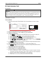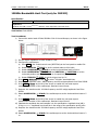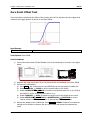
1
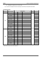
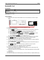
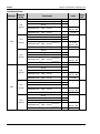
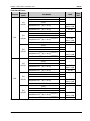
RIGOL Performance Verification Guide DS2000 Series Digital Oscilloscope Feb. 2014 RIGOL Technologies, Inc. RIGOL Guaranty and Declaration Copyright © 2012 RIGOL Technologies, Inc. All Rights Reserved. Trademark Information RIGOL is a registered trademark of RIGOL Technologies, Inc. Publication Number PVA13103-1110 Notices RIGOL products are protected by patent law in and outside of P.R.C. RIGOL reserves the right to modify or change parts of or all the specifications and pricing policies at company’s sole decision. Information in this publication replaces all previously corresponding material. RIGOL shall not be liable for losses caused by either incidental or consequential in connection with the furnishing, use or performance of this manual as well as any information contained. Any part of this document is forbidden to be copied or photocopied or rearranged without prior written approval of RIGOL. Product Certification RIGOL guarantees this product conforms to the national and industrial standards in China as well as the ISO9001:2008 standard and the ISO14001:2004 standard. Other international standard conformance certification is in progress. Contact Us If you have any problem or requirement when using our products or this manual, please contact RIGOL. E-mail: [email protected] Website: www.rigol.com DS2000 Performance Verification Guide I RIGOL General Safety Summary Please review the following safety precautions carefully before putting the instrument into operation so as to avoid any personal injuries or damages to the instrument and any product connected to it. To prevent potential hazards, please use the instrument only specified by this manual. Use Proper Power Cord. Only the power cord designed for the instrument and authorized by local country could be used. Ground The Instrument. The instrument is grounded through the Protective Earth lead of the power cord. To avoid electric shock, it is essential to connect the earth terminal of power cord to the Protective Earth terminal before any inputs or outputs. Connect the Probe Correctly. Do not connect the ground lead to high voltage since it has the isobaric electric potential as ground. Observe All Terminal Ratings. To avoid fire or shock hazard, observe all ratings and markers on the instrument and check your manual for more information about ratings before connecting. Use Proper Overvoltage Protection. Make sure that no overvoltage (such as that caused by a thunderstorm) can reach the product, or else the operator might expose to danger of electrical shock. Do Not Operate Without Covers. Do not operate the instrument with covers or panels removed. Use Proper Fuse. Please use the specified fuses. Avoid Circuit or Wire Exposure. Do not touch exposed junctions and components when the unit is powered. Do Not Operate With Suspected Failures. If you suspect damage occurs to the instrument, have it inspected by qualified service personnel before further operations. Any maintenance, adjustment or replacement especially to circuits or accessories must be performed by RIGOL authorized personnel. Keep Well Ventilation. II DS2000 Performance Verification Guide RIGOL Inadequate ventilation may cause increasing of temperature or damages to the device. So please keep well ventilated and inspect the intake and fan regularly. Do Not Operate in Wet Conditions. In order to avoid short circuiting to the interior of the device or electric shock, please do not operate in a humid environment. Do Not Operate in an Explosive Atmosphere. In order to avoid damages to the device or personal injuries, it is important to operate the device away from an explosive atmosphere. Keep Product Surfaces Clean and Dry. To avoid the influence of dust and/or moisture in air, please keep the surface of device clean and dry. Electrostatic Prevention. Operate in an electrostatic discharge protective area environment to avoid damages induced by static discharges. Always ground both the internal and external conductors of the cable to release static before connecting. Handling Safety Please handle with care during transportation to avoid damages to buttons, knob interfaces and other parts on the panels. DS2000 Performance Verification Guide III RIGOL Safety Terms and Symbols Terms on the Product. These terms may appear on the Product: DANGER indicates an injury or hazard may immediately happen. WARNING indicates an injury or hazard may be accessible potentially. CAUTION indicates a potential damage to the instrument or other property might occur. Symbols on the Product. These symbols may appear on the product: Hazardous Voltage IV Safety Warning Protective Earth Terminal Chassis Ground Test Ground DS2000 Performance Verification Guide RIGOL Contents Guaranty and Declaration .................................................................................................... I General Safety Summary ................................................................................................... II Safety Terms and Symbols................................................................................................. IV Document Overview ........................................................................................................... VI Chapter 1 Overview ....................................................................................................... 1-1 Test Preparations............................................................................................................ 1-1 Self-test .................................................................................................................. 1-1 Self-calibration......................................................................................................... 1-1 Test Result Record .......................................................................................................... 1-2 Chapter 2 Performance Verification Test ...................................................................... 2-1 Impedance Test ............................................................................................................. 2-2 DC Gain Accuracy Test .................................................................................................... 2-3 Bandwidth Test .............................................................................................................. 2-5 Bandwidth Limit Test ...................................................................................................... 2-7 20MHz Bandwidth Limit Test ..................................................................................... 2-8 100MHz Bandwidth Limit Test (only for DS2202) ....................................................... 2-11 Time Base Accuracy Test ............................................................................................... 2-14 Zero Point Offset Test ................................................................................................... 2-15 Appendix Test Record Form .................................................................................................1 DS2000 Performance Verification Guide V RIGOL Document Overview This manual guides users to correctly test the performance of RIGOL DS2000 series digital oscilloscope. Main topics in this manual: Chapter 1 Overview This chapter introduces the preparations and precautions of the performance verification test. Chapter 2 Performance Verification Test This chapter introduces the limit, test devices required as well as test method and procedures of each performance. Appendix Test Record Form In the appendix, a test record form is provided for recording the test results so as to determine whether each performance fulfills the requirement. Format Conventions in this Manual: Front Panel Key: denoted by “Text Box + Button Name (Bold)”, for example, Utility. Menu Softkey: denoted by “Character Shading + Menu Word (Bold)”, for example, Self-Cal. Operation Step: denoted by an arrow “”, for example, Utility Self-Cal. Content Conventions in this Manual: In this manual, DS2202 is taken as an example to illustrate the performance verification method. The introductions in this manual are applicable to all the models of the DS2000 series. Model DS2202 DS2102 DS2072 Analog Bandwidth 200 MHz 100 MHz 70 MHz Channels 2 2 2 Max Real-time Sample Rate 2 GSa/s Standard Memory Depth 14 Mpts Waveform Capture Rate Up to 50 000 wfs/s VI DS2000 Performance Verification Guide RIGOL Chapter 1 Overview Chapter 1 Overview Test Preparations The following preparations should be done before the test: 1. 2. 3. Self-test: perform self-test to make sure that the oscilloscope can work normally; Warm-up: warm the oscilloscope up for at least 30 minutes; Self-calibration: calibrate the oscilloscope. Self-test When the oscilloscope is in power-on state, press the power key at the lower left corner of the front panel to start the oscilloscope. During the start-up, the instrument performs a series of self-test items and users can hear the sound of relay switching. The welcome screen is displayed after the self-test is finished. If the self-test fails, make sure that the problems are found and resolved and do not perform self-calibration and performance test until the instrument passes the self-test. Self-calibration Before performing self-calibration, make sure that the oscilloscope has been warmed up for 30 minutes. Then, follow the steps below to perform the self-calibration. 1. Disconnect the connections of the two channels. 2. Press Utility Self-Cal; then press Start and the oscilloscope starts to execute the self-calibration program as shown in the figure below. DS2000 Performance Verification Guide 1-1 RIGOL Chapter 1 Overview 3. The self-calibration takes about 5 minutes. “Calibration finished, please restart the oscilloscope!” will be displayed when the self-calibration finishes and at this point, please restart the oscilloscope. 4. Press Acquire Acquisition and use to select “Average”. Then, press Averages and use to set the number of averages to 16. POSITION knob of each channel respectively to set the vertical 5. Press down the VERTICAL positions of the two channels to zero. View the distance between the waveform of each channel and the screen center at 1 mV/div scale. When this distance is greater than 0.2 div, please perform self-calibration again until the calibration succeeds (note: make sure that the instrument passes the self-calibration before performing the performance verification test; otherwise, the test results might not be accurate). Test Result Record Record and keep the test result of each test. In the Appendix of this manual, a test result record form which lists all the test items and their corresponding performance limits as well as spaces for users to record the test results, is provided. Tip: It is recommended that users photocopy the test record form before each test and record the test results in the copy so that the form can be used repeatedly. 1-2 DS2000 Performance Verification Guide RIGOL Chapter 2 Performance Verification Test Chapter 2 Performance Verification Test This chapter introduces the performance verification test method and procedures of DS2000 series digital oscilloscope by taking DS2202 as an example. You can perform the following tests in any order. In this manual, the test device used is Fluke 9500B. You can also use other devices that fulfill the specification requirements for the test. Recommended Device List: Device Specification Recommended Model Oscilloscope Calibrator Output range of DC voltage: 1 MΩ: 1 mV to 200 V 50 MΩ:1 mV to 200 V The rise time of fast edge signal: ≤ 150 ps Fluke 9500B Digital Multimeter The resistance measurement accuracy is higher than ±0.1% of reading RIGOL DM3058/3068 Test Cable BNC (male) to Dual-banana Plug Cable -- Signal Generator Frequency Accuracy: ±1 ppm RIGOL DG5000 series Test Cable BNC (m)-BNC (m) cable -- Note: 1. Make sure that the oscilloscope passes the self-test and self-calibration before executing performance verification test. 2. Make sure that the oscilloscope has been warmed up for at least 30 minutes before executing any of the following tests. 3. Please reset the instrument to the factory setting before or after executing any of the following tests. DS2000 Performance Verification Guide 2-1 RIGOL Chapter 2 Performance Verification Test Impedance Test Specification: Input Impedance 0.99 MΩ to 1.01 MΩ Test Devices: Fluke 9500B or Digital Multimeter and BNC (male) to Dual-banana Plug Cable. In this manual, the test device is Fluke 9500B. Test Procedures: 1. Impedance test of CH1 and CH2 1) Connect the active head of Fluke 9500B to CH1 of the oscilloscope, as shown in figure below. 2) 3) 4) 5) 2. Configure the oscilloscope: a) Press CH1 in the vertical control area (VERTICAL) at the front panel to enable CH1. b) Rotate VERTICAL SCALE to set the vertical scale of CH1 to 100 mV/div. Enable the Fluke 9500B and select the resistance measurement function, read and record the resistance measurement value. SCALE to adjust the vertical scale of CH1 to 500 mV/div; then, read Rotate VERTICAL and record the resistance measurement value. Turn CH1 off. Repeat the above test steps to test CH2 and record the test results. Impedance test of [EXT TRIG] channel: 1) Disconnect the connections of the two input channels. 2) Connect the active head of Fluke 9500B to the external trigger channel [EXT TRIG] of the oscilloscope. 3) Enable the Fluke 9500B and select the resistance measurement function, read and record the resistance measurement value. Test Record Form: Channel CH1 CH2 EXT TRIG 2-2 Vertical Scale Test Result Limit Pass/Fail 100 mV/div 500 mV/div 100 mV/div ≥ 0.99 MΩ and ≤ 1.01 MΩ 500 mV/div -- DS2000 Performance Verification Guide Chapter 2 Performance Verification Test RIGOL DC Gain Accuracy Test Specification: DC Gain Accuracy ≤2%×Full Scale Explanation: Full Scale = 8 div×vertical scale. Relative error of each scale: |(Vavg1–Vavg2)–(Vout1-Vout2)|/Full Scale×100%≤2%; otherwise, the test fails. For example, when the vertical scale is 1 V/div, input DC signals with +3 VDC and -3 VDC voltages respectively, the values of Vavg1 and Vavg2 are +3.06 V and -3.04 V respectively, the relative error is |(+3.06 V-(-3.04 V))-(+3 V-(-3 V)) |/(1 V/div*8 div) × 100% = 1.25% and the test passes. Test Device: Fluke 9500B Test Procedures: 1) Connect the active head of Fluke 9500B to CH1 of the oscilloscope, as shown in figure below. 2) 3) 4) 5) 6) 7) 8) 9) Enable the Fluke 9500B and set the output impedance to 1 MΩ. Output a DC signal with +1.5 mVDC voltage (Vout1) from Fluke 9500B. Configure the oscilloscope: a) Press CH1 in the vertical control area (VERTICAL) at the front panel to enable CH1. b) Rotate VERTICAL SCALE to set the vertical scale to 500 μV/div. c) Rotate HORIZONTAL SCALE to set the horizontal time base to 10 μs. d) Rotate VERTICAL POSITION to set the vertical position to 0. e) Press Acquire Acquisition and use to select “Average”. Then, press Averages and use to set the number of averages to 32. Press MENU Vavg at the left of the screen to enable the average measurement function of the oscilloscope. Read and record Vavg1. Adjust Fluke 9500B to output a DC signal with -1.5 mVDC output voltage (Vout2). Press MENU Vavg at the left of the screen to enable the average measurement function of the oscilloscope. Read and record Vavg2. Calculate the relative error of the vertical scale: |(Vavg1–Vavg2)–(Vout1-Vout2)|/Full Scale×100%. Keep other settings of the oscilloscope unchanged: a) Set the vertical scale to 1 mV/div、2 mv/div, 5 mV/div, 10 mV/div, 20 mV/div, 50 mV/div, 100 mV/div, 200 mV/div, 500 mV/div, 1 V/div, 2 V/div, 5 V/div and 10 V/div respectively. b) Adjust the output voltage of Fluke 9500B to ±3 div respectively. c) Repeat steps 1), 2), 3), 4), 5) and 6) and record the test results. DS2000 Performance Verification Guide 2-3 RIGOL Chapter 2 Performance Verification Test d) Calculate the relative error of each scale. 10) Turn CH1 off. Repeat the above test steps to test CH2 and record the test results. Test Record Form: Channel Vertical Scale Test Result Vavg1 Vavg2 Calculation Result[1] Limit Pass/Fail 500 μV/div 1 mV/div 2 mV/div 5 mV/div 10 mV/div 20 mV/div CH1 50 mV/div 100 mV/div 200 mV/div 500 mV/div 1 V/div 2 V/div 5 V/div 10 V/div 500 μV/div ≤ 2% 1 mV/div 2 mV/div 5 mV/div 10 mV/div 20 mV/div CH2 50 mV/div 100 mV/div 200 mV/div 500 mV/div 1 V/div 2 V/div 5 V/div 10 V/div Note[1]: the calculation formula is |(Vavg1–Vavg2)–(Vout1-Vout2)|/Full Scale×100%; wherein, Vout1 and Vout2 are 3 and -3 times of the current vertical scale respectively. 2-4 DS2000 Performance Verification Guide Chapter 2 Performance Verification Test RIGOL Bandwidth Test Specification: Amplitude Loss -3 dB to 1 dB Explanation: Amplitude loss (dB) = 20×lg(Vrms2/Vrms1). Test device: Fluke 9500B Test Procedures: 1) Connect the active head of Fluke 9500B to CH1 of the oscilloscope, as shown in figure below. 2) 3) 4) 5) 6) 7) 8) 9) 10) 11) 12) 13) Enable the Fluke 9500B and set the output impedance to 1 MΩ. Configure the oscilloscope: a) Press CH1 in the vertical control area (VERTICAL) at the front panel to enable CH1. b) Rotate HORIZONTAL SCALE to set the horizontal time base to 200 ns. c) Rotate VERTICAL SCALE to set the vertical scale to 100 mV/div. d) Rotate HORIZONTAL POSITION and VERTICAL POSITION to set the horizontal position and vertical position to 0 respectively. e) Rotate TRIGGER LEVEL to set the trigger level to 0 V. Output a sine signal with 1 MHz frequency and 600 mVpp amplitude from Fluke 9500B. Press MENU Vrms at the left of the screen to enable the root mean square measurement function of the oscilloscope. Read and record Vrms1. Output a sine signal with 200 MHz frequency (100 MHz for DS2102; 70 MHz for DS2072) and 600 mVpp amplitude from Fluke 9500B. SCALE of the oscilloscope to set the horizontal time base to 5 Rotate HORIZONTAL ns. Press MENU Vrms at the left of the screen to enable the root mean square measurement function of the oscilloscope. Read and record Vrms2. Calculate the amplitude loss: amplitude loss (dB) = 20×lg(Vrms2/Vrms1). Keep the other settings of the oscilloscope unchanged and set the vertical scale to 200 mV/div and 500 mV/div respectively. Output sine signals with 1 MHz frequency and 1.2 Vpp/3 Vpp amplitude from Fluke 9500B respectively. Repeat step 5). Output sine signals with 200 MHz frequency (100 MHz for DS2102; 70 MHz for DS2072) and DS2000 Performance Verification Guide 2-5 RIGOL Chapter 2 Performance Verification Test 1.2 Vpp/3 Vpp amplitude from Fluke 9500B respectively. 14) Repeat steps 7), 8) and 9). 15) Turn CH1 off. Test CH2 according to the above test steps and record the test results. Test Record Form: Channel Vertical Scale Test Result Limit Pass/Fail Vrms1 100 mV/div Vrms2 Amplitude Loss[1] Vrms1 CH1 200 mV/div Vrms2 Amplitude Loss Vrms1 500 mV/div Vrms2 Amplitude Loss Vrms1 100 mV/div ≥ -3 dB and ≤ 1 dB Vrms2 Amplitude Loss Vrms1 CH2 200 mV/div Vrms2 Amplitude Loss Vrms1 500 mV/div Vrms2 Amplitude Loss [1] Note 2-6 (Vrms2/Vrms1) : amplitude loss (dB) = 20×lg . DS2000 Performance Verification Guide RIGOL Chapter 2 Performance Verification Test Bandwidth Limit Test Bandwidth limit test verifies the 20 MHz bandwidth limit and 100 MHz bandwidth limit functions respectively. The bandwidth limits available for oscilloscopes with different bandwidths are different. Model Bandwidth Limit DS2202 20 MHz/100 MHz DS2102 20 MHz DS2072 20 MHz DS2000 Performance Verification Guide 2-7 RIGOL Chapter 2 Performance Verification Test 20MHz Bandwidth Limit Test Specification: Amplitude Loss -3 dB to 1 dB Explanation: Amplitude Loss (dB) = 20×lg(Vrmsn/Vrms1). Wherein, Vrmsn represents Vrms2 and Vrms3. Test Device: Fluke 9500B Test Procedures: 1) Connect the active head of Fluke 9500B to CH1 of the oscilloscope, as shown in the figure below. 2) 3) 4) 5) 6) 7) 8) 9) 10) 11) 12) 13) 2-8 Set the output impedance of Fluke 9500B to 1 MΩ. Configure the oscilloscope: a) Press CH1 in the vertical control area (VERTICAL) at the front panel to enable CH1. b) Rotate VERTICAL SCALE to set the vertical scale to 100 mV/div. c) Rotate HORIZONTAL SCALE to set the horizontal time base to 200 ns. d) Rotate HORIZONTAL POSITION and VERTICAL POSITION to set the horizontal position and vertical position to 0 respectively. e) Rotate TRIGGER LEVEL to set the trigger level to 0 V. Press CH1 BW Limit and use to select “20 MHz” bandwidth limit. Output a sine waveform with 1 MHz frequency and 600 mVpp amplitude from Fluke 9500B. Press MENU Vrms at the left of the screen to enable the root mean square measurement function of the oscilloscope. Read and record Vrms1. Output a sine waveform with 20 MHz frequency and 600 mVpp amplitude from Fluke 9500B. SCALE of the oscilloscope to set the horizontal time base to 20 Rotate HORIZONTAL ns. Press MENU Vrms at the left of the screen to enable the root mean square measurement function of the oscilloscope. Read and record Vrms2. Calculate the amplitude loss and compare it to the specification: Amplitude Loss (dB) = 20×lg(Vrms2/Vrms1). Amplitude loss should be in the range of the specification at this point. Output a sine waveform with 50 MHz frequency and 600 mVpp amplitude from Fluke 9500B. SCALE of the oscilloscope to set the horizontal time base to 10 Rotate HORIZONTAL ns. Press MENU Vrms at the left of the screen to enable the root mean square measurement function of the oscilloscope. Read and record Vrms3. DS2000 Performance Verification Guide Chapter 2 Performance Verification Test RIGOL 14) Calculate the amplitude loss and compare it to the specification: Amplitude Loss (dB) = 20×lg(Vrms3/Vrms1). Amplitude loss should be lower than -3 dB at this point. 15) Keep other settings of the oscilloscope unchanged and set the vertical scale to 200 mV/div. 16) Output a sine waveform with 1 MHz frequency and 1.2 Vpp amplitude from Fluke 9500B. 17) Repeat step 6). 18) Output a sine waveform with 20 MHz frequency and 1.2 Vpp amplitude from Fluke 9500B. 19) Repeat step 8), 9) and 10). 20) Output a sine waveform with 50 MHz frequency and 1.2 Vpp amplitude from Fluke 9500B. 21) Repeat step 12), 13) and 14). 22) Keep other settings of the oscilloscope unchanged and set the vertical scale to 500 mV/div. 23) Output a sine waveform with 1 MHz frequency and 3 Vpp amplitude from Fluke 9500B. 24) Repeat step 6). 25) Output a sine waveform with 20 MHz frequency and 3 Vpp amplitude from Fluke 9500B. 26) Repeat step 8), 9) and 10). 27) Output a sine waveform with 50 MHz frequency and 3 Vpp amplitude from Fluke 9500B. 28) Repeat step 12), 13) and 14). 29) Turn CH1 off. Test CH2 according to the above test steps and record the test results. DS2000 Performance Verification Guide 2-9 RIGOL Chapter 2 Performance Verification Test Test Record Form: Channel Vertical Scale Test Result Limit Pass/ Fail Vrms1 -- Vrms2 100 mV/div Vrms3 Amplitude Loss[1] (dB) = 20×lg(Vrms2/Vrms1) ≥ -3 dB and ≤ 1 dB Amplitude Loss[1] (dB) = 20×lg(Vrms3/Vrms1) ≤ 3 dB Vrms1 Vrms2 CH1 200 mV/div -- Vrms3 Amplitude Loss[1] (dB) = 20×lg(Vrms2/Vrms1) ≥ -3 dB and ≤ 1 dB Amplitude Loss[1] (dB) = 20×lg(Vrms3/Vrms1) ≤ 3 dB Vrms1 Vrms2 500 mV/div -- Vrms3 Amplitude Loss[1] (dB) = 20×lg(Vrms2/Vrms1) ≥ -3 dB and ≤ 1 dB Amplitude Loss[1] (dB) = 20×lg(Vrms3/Vrms1) ≤ 3 dB Vrms1 -- Vrms2 100 mV/div Vrms3 Amplitude Loss[1] (dB) = 20×lg(Vrms2/Vrms1) ≥ -3 dB and ≤ 1 dB Amplitude Loss[1] (dB) = 20×lg(Vrms3/Vrms1) ≤ 3 dB Vrms1 Vrms2 CH2 200 mV/div -- Vrms3 Amplitude Loss[1] (dB) = 20×lg(Vrms2/Vrms1) ≥ -3 dB and ≤ 1 dB Amplitude Loss[1] (dB) = 20×lg(Vrms3/Vrms1) ≤ 3 dB Vrms1 Vrms2 500 mV/div [1] Note 2-10 -- Vrms3 Amplitude Loss[1] (dB) = 20×lg(Vrms2/Vrms1) ≥ -3 dB and ≤ 1 dB Amplitude Loss[1] (dB) = 20×lg(Vrms3/Vrms1) ≤ 3 dB (Vrmsn/Vrms1) : amplitude loss (dB) = 20×lg . Here, Vrmsn represents Vrms2 and Vrms3. DS2000 Performance Verification Guide Chapter 2 Performance Verification Test RIGOL 100MHz Bandwidth Limit Test (only for DS2202) Specification: Amplitude Loss -3 dB to 1 dB Explanation: Amplitude Loss (dB) = 20×lg(Vrmsn/Vrms1). Wherein, Vrmsn represents Vrms2 and Vrms3. Test Device: Fluke 9500B Test Procedures: 1) Connect the active head of Fluke 9500B to CH1 of the oscilloscope, as shown in the figure below. 2) 3) Set the output impedance of Fluke 9500B to 1 MΩ. Configure the oscilloscope: a) Press CH1 in the vertical control area (VERTICAL) at the front panel to enable CH1. b) Rotate VERTICAL SCALE to set the vertical scale to 100 mV/div. c) Rotate HORIZONTAL SCALE to set the horizontal time base to 200 ns. d) Rotate HORIZONTAL POSITION and VERTICAL POSITION to set the horizontal position and vertical position to 0 respectively. e) Rotate TRIGGER LEVEL to set the trigger level to 0 V. 4) Press CH1 BW Limit and use to select “100 MHz” bandwidth limit. 5) Output a sine waveform with 1 MHz frequency and 600 mVpp amplitude from Fluke 9500B. 6) Press MENU Vrms at the left of the screen to enable the root mean square measurement function of the oscilloscope. Read and record Vrms1. 7) Output a sine waveform with 100 MHz frequency and 600 mVpp amplitude from Fluke 9500B. SCALE of the oscilloscope to set the horizontal time base to 5 8) Rotate HORIZONTAL ns. 9) Press MENU Vrms at the left of the screen to enable the root mean square measurement function of the oscilloscope. Read and record Vrms2. 10) Calculate the amplitude loss and compare it to the specification: Amplitude Loss (dB) = 20×lg(Vrms2/Vrms1). Amplitude loss should be in the range of the specification at this point. 11) Output a sine waveform with 200 MHz frequency and 600 mVpp amplitude from Fluke 9500B. SCALE of the oscilloscope to set the horizontal time base to 2 12) Rotate HORIZONTAL ns. DS2000 Performance Verification Guide 2-11 RIGOL Chapter 2 Performance Verification Test 13) Press MENU Vrms at the left of the screen to enable the root mean square measurement function of the oscilloscope. Read and record Vrms3. 14) Calculate the amplitude loss and compare it to the specification: Amplitude Loss (dB) = 20×lg(Vrms3/Vrms1). Amplitude loss should be lower than -3 dB at this point. 15) Keep other settings of the oscilloscope unchanged and set the vertical scale to 200 mV/div. 16) Output a sine waveform with 1 MHz frequency and 1.2 Vpp amplitude from Fluke 9500B. 17) Repeat step 6). 18) Output a sine waveform with 100 MHz frequency and 1.2 Vpp amplitude from Fluke 9500B. 19) Repeat step 8), 9) and 10). 20) Output a sine waveform with 200 MHz frequency and 1.2 Vpp amplitude from Fluke 9500B. 21) Repeat step 12), 13) and 14). 22) Keep other settings of the oscilloscope unchanged and set the vertical scale to 500 mV/div. 23) Output a sine waveform with 1 MHz frequency and 3 Vpp amplitude from Fluke 9500B. 24) Repeat step 6). 25) Output a sine waveform with 100 MHz frequency and 3 Vpp amplitude from Fluke 9500B. 26) Repeat step 8), 9) and 10). 27) Output a sine waveform with 200 MHz frequency and 3 Vpp amplitude from Fluke 9500B. 28) Repeat step 12), 13) and 14). 29) Turn CH1 off. Test CH2 according to the above test steps and record the test results. 2-12 DS2000 Performance Verification Guide RIGOL Chapter 2 Performance Verification Test Test Record Form: Channel Vertical Scale Test Result Limit Pass/ Fail Vrms1 -- Vrms2 100 mV/div Vrms3 Amplitude Loss[1] (dB) = 20×lg(Vrms2/Vrms1) ≥ -3 dB and ≤ 1 dB Amplitude Loss[1] (dB) = 20×lg(Vrms3/Vrms1) ≤ 3 dB Vrms1 Vrms2 CH1 200 mV/div -- Vrms3 Amplitude Loss[1] (dB) = 20×lg(Vrms2/Vrms1) ≥ -3 dB and ≤ 1 dB Amplitude Loss[1] (dB) = 20×lg(Vrms3/Vrms1) ≤ 3 dB Vrms1 Vrms2 500 mV/div -- Vrms3 Amplitude Loss[1] (dB) = 20×lg(Vrms2/Vrms1) ≥ -3 dB and ≤ 1 dB Amplitude Loss[1] (dB) = 20×lg(Vrms3/Vrms1) ≤ 3 dB Vrms1 -- Vrms2 100 mV/div Vrms3 Amplitude Loss[1] (dB) = 20×lg(Vrms2/Vrms1) ≥ -3 dB and ≤ 1 dB Amplitude Loss[1] (dB) = 20×lg(Vrms3/Vrms1) ≤ 3 dB Vrms1 Vrms2 CH2 200 mV/div -- Vrms3 Amplitude Loss[1] (dB) = 20×lg(Vrms2/Vrms1) ≥ -3 dB and ≤ 1 dB Amplitude Loss[1] (dB) = 20×lg(Vrms3/Vrms1) ≤ 3 dB Vrms1 Vrms2 500 mV/div [1] Note -- Vrms3 Amplitude Loss[1] (dB) = 20×lg(Vrms2/Vrms1) ≥ -3 dB and ≤ 1 dB Amplitude Loss[1] (dB) = 20×lg(Vrms3/Vrms1) ≤ 3 dB (Vrmsn/Vrms1) : amplitude loss (dB) = 20×lg DS2000 Performance Verification Guide . Wherein, Vrmsn represents Vrms2 and Vrms3. 2-13 RIGOL Chapter 2 Performance Verification Test Time Base Accuracy Test Specification: Time Base Accuracy [1] ≤ ±(25 ppm + 5 ppm/year×completed years of service[2]) Note[1]: typical value. Note[2]: for the completed years of service of the instrument, calculate it according to the date in the verification certificate provided when the instrument left the factory. Test Devices: Fluke 9500B Test Procedures: 1) Connect the active head of Fluke 9500B to CH1 of the oscilloscope, as shown in the figure below. 2) 3) 4) 5) 6) Output a sine waveform with 1 MHz frequency and 1 Vpp amplitude from Fluke 9500B. Configure the oscilloscope: a) Press CH1 in the vertical control area (VERTICAL) at the front panel to enable CH1. b) Rotate VERTICAL SCALE to set the vertical scale to 200 mV/div. c) Rotate VERTICAL POSITION to set the vertical position to 0. d) Rotate HORIZONTAL SCALE to set the horizontal time base to 10 ns. e) Rotate HORIZONTAL POSITION to set the horizontal position to 1 ms. Observe the display of the oscilloscope and measure the offset (ΔT) of the midpoint of the signal relative to the center of the screen. Calculate the time base accuracy, namely the ratio of ΔT to the horizontal position of the oscilloscope. For example, if the offset of this test is 8 ns, the time base accuracy is 8 ns/1 ms=8 ppm. Calculate the limit of the time base accuracy using the limit formula “±(25 ppm + 5 ppm/year×completed years of service)”. Test Record Form: Channel Test Result ΔT Calculation Result CH1 Limit Pass/Fail ≤ ±(25 ppm + 5 ppm/year×completed years of service[1]) Note [1]: for the completed years of service of the instrument, calculate it according to the date in the verification certificate provided when the instrument left the factory. 2-14 DS2000 Performance Verification Guide Chapter 2 Performance Verification Test RIGOL Zero Point Offset Test Zero point offset is defined as the offset of the crossing point of the waveform and the trigger level relative to the trigger position as shown in the figure below. Specification: Zero Point Offset 500 ps Test Devices: Fluke 9500B Test Procedures: 1) Connect the active head of Fluke 9500B to CH1 of the oscilloscope, as shown in the figure below. 2) 3) 4) Output a fast edge signal with 150 ps rise time and 600 mV amplitude from Fluke 9500B. Configure the oscilloscope: a) Press CH1 in the vertical control area (VERTICAL) at the front panel to enable CH1. b) Rotate VERTICAL SCALE to set the vertical scale to 100 mV/div. c) Rotate HORIZONTAL SCALE to set the horizontal time base to 2 ns (for DS2102 and DS2072, set the horizontal time base to 5 ns). d) Rotate TRIGGER LEVEL to adjust the trigger level to the middle of the screen. e) Rotate VERTICAL POSITION and HORIZONTAL POSITION to set the vertical position and horizontal position to appropriate values respectively. Observe the display of the oscilloscope. Press Cursor Mode “Manual” to enable the manual cursor function to measure the zero point offset and record the measurement result. DS2000 Performance Verification Guide 2-15 RIGOL 5) 6) 7) Chapter 2 Performance Verification Test Keep other settings unchanged and adjust the amplitude of the fast edge signal to 3 V. Set the vertical scale to 500 mV/div. Measure the zero point offset according to the above method and record the test result. Turn CH1 off. Repeat the above test steps to measure CH2 and record the test results. Test Record Form: Channel CH1 CH2 2-16 Fast Edge Signal Amplitude Vertical Scale 600 mV 100 mV/div 3V 500 mV/div 600 mV 100 mV/div 3V 500 mV/div Test Result Limit Pass/Fail ≤ 500 ps DS2000 Performance Verification Guide RIGOL Appendix Test Record Form Appendix Test Record Form RIGOL DS2000 Series Digital Oscilloscope Performance Verification Test Record Form Model: Tested by: Test Date: Impedance Test: Channel CH1 CH2 EXT TRIG Vertical Scale Test Result Limit Pass/Fail 100 mV/div 500 mV/div 100 mV/div ≥ 0.99 MΩ and ≤ 1.01 MΩ 500 mV/div -- DS2000 Performance Verification Guide 1 RIGOL Appendix Test Record Form DC Gain Accuracy Test: Channel Vertical Scale Test Result Vavg1 Vavg2 Calculation Result[1] Limit Pass/Fail 500 μV/div 1 mV/div 2 mV/div 5 mV/div 10 mV/div 20 mV/div CH1 50 mV/div 100 mV/div 200 mV/div 500 mV/div 1 V/div 2 V/div 5 V/div 10 V/div 500 μV/div ≤ 2% 1 mV/div 2 mV/div 5 mV/div 10 mV/div 20 mV/div CH2 50 mV/div 100 mV/div 200 mV/div 500 mV/div 1 V/div 2 V/div 5 V/div 10 V/div [1] Note : the calculation formula is |(Vavg1–Vavg2)–(Vout1-Vout2)|/Full Scale×100%; wherein, Vout1 and Vout2 are 3 and -3 times of the current vertical scale respectively. 2 DS2000 Performance Verification Guide RIGOL Appendix Test Record Form Bandwidth Test: Channel Vertical Scale Test Result Limit Pass/Fail Vrms1 100 mV/div Vrms2 Amplitude Loss[1] Vrms1 CH1 200 mV/div Vrms2 Amplitude Loss Vrms1 500 mV/div Vrms2 Amplitude Loss Vrms1 100 mV/div ≥ -3 dB and ≤ 1 dB Vrms2 Amplitude Loss Vrms1 CH2 200 mV/div Vrms2 Amplitude Loss Vrms1 500 mV/div Vrms2 Amplitude Loss [1] Note (Vrms2/Vrms1) : amplitude loss (dB) = 20×lg DS2000 Performance Verification Guide . 3 RIGOL Appendix Test Record Form 20 MHz Bandwidth Limit Test: Channel Vertical Test Result Scale Limit Pass/F ail Vrms1 Vrms2 100 mV/div -- Vrms3 Amplitude Loss [1] (dB) = 20×lg(Vrms2/Vrms1) Amplitude Loss [1] (Vrms3/Vrms1) (dB) = 20×lg ≥ -3 dB and ≤ 1 dB ≤ 3 dB Vrms1 CH1 Vrms2 200 mV/div -- Vrms3 Amplitude Loss [1] (dB) = 20×lg(Vrms2/Vrms1) Amplitude Loss [1] (Vrms3/Vrms1) (dB) = 20×lg ≥ -3 dB and ≤ 1 dB ≤3 dB Vrms1 mV/div -- Vrms2 500 Vrms3 Amplitude Loss [1] (dB) = 20×lg(Vrms2/Vrms1) Amplitude Loss [1] (Vrms3/Vrms1) (dB) = 20×lg ≥ -3 dB and ≤ 1 dB ≤ 3 dB Vrms1 mV/div -- Vrms2 100 Vrms3 Amplitude Loss [1] (dB) = 20×lg(Vrms2/Vrms1) Amplitude Loss[1] (dB) = 20×lg(Vrms3/Vrms1) ≥ -3 dB and ≤ 1 dB ≤ 3 dB Vrms1 CH2 Vrms2 200 mV/div -- Vrms3 Amplitude Loss [1] (dB) = 20×lg(Vrms2/Vrms1) Amplitude Loss [1] (Vrms3/Vrms1) (dB) = 20×lg ≥ -3 dB and ≤ 1 dB ≤ 3 dB Vrms1 Vrms2 500 mV/div [1] Note 4 -- Vrms3 Amplitude Loss [1] (dB) = 20×lg(Vrms2/Vrms1) Amplitude Loss [1] (Vrms3/Vrms1) (dB) = 20×lg ≥ -3 dB and ≤ 1 dB ≤ 3 dB (Vrmsn/Vrms1) : amplitude loss (dB) = 20×lg . Wherein, Vrmsn represents Vrms2 and Vrms3. DS2000 Performance Verification Guide RIGOL Appendix Test Record Form 100 MHz Bandwidth Limit Test (only for DS2202): Channel Vertical Test Result Scale Pass/F Limit ail Vrms1 Vrms2 100 mV/div -- Vrms3 Amplitude Loss [1] (dB) = 20×lg(Vrms2/Vrms1) Amplitude Loss [1] (Vrms3/Vrms1) ≥ -3 dB and ≤ 1 dB (dB) = 20×lg ≤ 3 dB Vrms1 CH1 Vrms2 200 mV/div -- Vrms3 Amplitude Loss [1] (dB) = 20×lg(Vrms2/Vrms1) Amplitude Loss [1] (Vrms3/Vrms1) ≥ -3 dB and ≤ 1 dB (dB) = 20×lg ≤3 dB Vrms1 mV/div -- Vrms2 500 Vrms3 Amplitude Loss [1] (dB) = 20×lg(Vrms2/Vrms1) Amplitude Loss [1] (Vrms3/Vrms1) ≥ -3 dB and ≤ 1 dB (dB) = 20×lg ≤ 3 dB Vrms1 mV/div -- Vrms2 100 Vrms3 Amplitude Loss [1] (dB) = 20×lg(Vrms2/Vrms1) ≥ -3 dB and ≤ 1 dB Amplitude Loss[1] (dB) = 20×lg(Vrms3/Vrms1) ≤ 3 dB Vrms1 CH2 Vrms2 200 mV/div -- Vrms3 Amplitude Loss [1] (dB) = 20×lg(Vrms2/Vrms1) Amplitude Loss [1] (Vrms3/Vrms1) ≥ -3 dB and ≤ 1 dB (dB) = 20×lg ≤ 3 dB Vrms1 Vrms2 500 mV/div [1] Note -- Vrms3 Amplitude Loss [1] (dB) = 20×lg(Vrms2/Vrms1) Amplitude Loss [1] (Vrms3/Vrms1) ≥ -3 dB and ≤ 1 dB (dB) = 20×lg ≤ 3 dB (Vrmsn/Vrms1) : amplitude loss (dB) = 20×lg . Wherein, Vrmsn represents Vrms2 and Vrms3. Time Base Accuracy Test: Channel Test Result ΔT Calculation Result CH1 Limit Pass/Fail ±(25 ppm + 5 ppm/year×completed years of service[1]) Note[1]: for the completed years of service of the instrument, calculate it according to the date in the verification certificate provided when the instrument left factory. DS2000 Performance Verification Guide 5 RIGOL Appendix Test Record Form Zero Point Offset Test: Channel CH1 CH2 6 Fast Edge Signal Amplitude Vertical Scale 600 mV 100 mV/div 3V 500 mV/div 600 mV 100 mV/div 3V 500 mV/div Test Result Limit Pass/Fail ≤ 500 ps DS2000 Performance Verification Guide