1
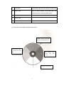
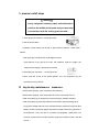
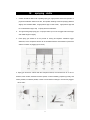
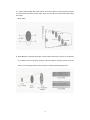
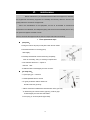
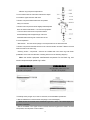
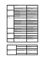
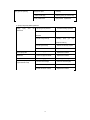
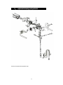
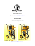
Operation manual for Airless paint
sprayer
High Pressure Electric Airless paint sprayer Titan 440i model
intelligent series
Remark: this guide manual is the same with model DP-6389 ,the content include :the
operation of equipment,cleaning ,maintenance ,and repair,be sure to pre-operational ,read
the manual carefully before you use this machine.
1. warning and precautions
Safety Precautions
This manual contains information that must be read and understood before using
the airless sprayer equipment. When you come to an area that has one of the following
symbols, pay particular attention and make certain to heed the safeguard.
WARNING
This symbol indicates a potential hazard that may cause serious injury or loss of life.
Important safety information will follow.
CAUTION
This symbol indicates a potential hazard to you or to the equipment. Important information
that tells how to prevent
damage to the equipment or how to avoid causes of minor injuries will follow.
NOTE: Notes give important information which should be given special attention.
WARNING
HAZARD: Injection injury – A high pressure fluid stream produced by this equipment can
pierce the
skin and underlying tissues, leading to serious injury and possible amputation. See a
physician immediately.
DO NOT TREAT AN INJECTION INJURY AS A SIMPLE CUT! Injection can lead to
amputation. See a physician immediately.
The maximum operating range of the sprayer is 3200 PSI/221BAR fluid pressure.
PREVENTION:
• NEVER aim the airless spray gun at any part of the body.
• NEVER allow any part of the body to touch the fluid stream. DO NOT allow body to touch
a leak in the fluid hose.
• NEVER put hand in front of the gun. Gloves will not provide protection against an
injection injury.
• ALWAYS lock gun trigger, shut pump off, and release all pressure before servicing,
cleaning tip or guard, changing
tip, or leaving unattended. Pressure will not be released by turning off the motor. The
PRIME/SPRAY valve handle
must be turned to PRIME to relieve the pressure. Refer to the PRESSURE RELIEF
PRESSURE described in the pump manual.
• ALWAYS keep airless tip guard in place while spraying. The tip guard provides some
protection but is mainly a warning device.
• ALWAYS remove the spray tip before flushing or cleaning the system.
• Paint hose can develop leaks from wear, kinking and abuse. A leak can inject material
into the skin. Inspect the hose before each use.
• NEVER use a spray gun without a working trigger lock and trigger guard in place.
• All accessories must be rated at or above 3200 PSI/221 BAR. This includes spray tips,
guns, extensions, and hose.
2
NOTE TO PHYSICIAN:
Injection into the skin is a traumatic injury. It is important to treat the injury as soon as
possible. DO NOT delay treatment to research toxicity. Toxicity is a concern with some
coatings injected directly into the blood stream. Consultation with a plastic surgeon or
reconstructive hand surgeon may be advisable.
HAZARD: EXPLOSION AND FIRE – Solvent and paint
fumes can explode or ignite. Severe injury and/or property damage can occur.
PREVENTION:
• Provide extensive exhaust and fresh air introduction to keep the air within the spray area
free from accumulation of flammable vapors.
• Avoid all ignition sources such as static electricity sparks, electrical appliances, flames,
pilot lights, hot objects, and sparks from connecting and disconnecting power cords or
working light switches.
• Do not smoke in spray area.
• Fire extinguisher must be present and in good working order.
• Place pump at least 20 feet (6.1 m) from the spray object in a well ventilated area (add
more hose if necessary).
Flammable vapors are often heavier than air. Floor area must be extremely well ventilated.
The pump contains arcing parts that emit sparks and can ignite vapors.
• The equipment and objects in and around the spray area must be properly grounded to
prevent static sparks.
• Use only conductive or grounded high-pressure fluid hose. Gun must be grounded
through hose connections.
• Power cord must be connected to a grounded circuit.
• Always flush unit into separate metal container, at low pump pressure, with spray tip
removed. Hold gun firmly against side of container to ground container and prevent static
sparks.
• Follow material and solvent manufacturer’s warnings and instructions.
• Use extreme caution when using materials with a flashpoint below 70° F (21° C).
Flashpoint is the temperature at which a fluid can produce enough vapors to ignite.
• Plastic can cause static sparks. Never hang plastic to enclose spray area. Do not use
plastic drop cloths when spraying flammable materials.
• Use lowest possible pressure to flush equipment.
GAS ENGINE (WHERE APPLICABLE)
Always place sprayer outside of structure in fresh air. Keep all solvents away from engine
exhaust. Never fill fuel tank with a running or hot engine. Hot surface can ignite spilled fuel.
Always attach ground wire from pump to a grounded object. Refer to engine owner’s
manual for complete safety information.
HAZARD: EXPLOSION HAZARD DUE TO INCOMPATIBLE
MATERIALS – will cause severe injury or property damage.
PREVENTION:
• Do not use materials containing bleach or chlorine.
• Do not use halogenated hydrocarbon solvents such as bleach, mildewcide, methylene
chloride and 1,1,1 – trichloroethane. They are not compatible with aluminum.
3
• Contact your coating supplier about the compatibility of material with aluminum.
HAZARD: HAZARDOUS VAPORS – Paints, solvents, insecticides, and other materials
can be harmful if inhaled or come in contact with body. Vapors can cause severe nausea,
fainting, or poisoning.
PREVENTION:
• Use a respirator or mask if vapors can be inhaled. Read all instructions supplied with the
mask to be sure it will provide the necessary protection.
• Wear protective eyewear.
• Wear protective clothing as required by coating manufacturer.
HAZARD: GENERAL – Can cause severe injury or property damage.
PREVENTION:
• Read all instructions and safety precautions before operating equipment.
• Follow all appropriate local, state, and national codes governing ventilation, fire
prevention, and operation.
• The United States Government Safety Standards have been adopted under the
Occupational Safety and Health Act (OSHA). These standards, particularly part 1910 of
the General Standards and part 1926 of the Construction Standards, should be consulted.
• Use only manufacturer authorized parts. User assumes all risks and liabilities when
using parts that do not meet the minimum specifications and safety devices of the pump
manufacturer.
• Before each use, check all hoses for cuts, leaks, abrasion or bulging of cover. Check for
damage or movement of couplings. Immediately replace hose if any of those conditions
exist. Never repair a paint hose. Replace with a grounded high-pressure hose.
• All hoses, swivels, guns, and accessories must be pressure rated at or above
3200PSI/221 BAR.
• Do not spray outdoors on windy days.
• Wear clothing to keep paint off skin and hair.
• Always unplug cord from outlet before working on equipment.
Grounding Instructions
This product must be grounded. In the event of an electrical short circuit, grounding
reduces the risk of electric shock by providing an escape wire for the electric current. This
product is equipped with a cord having a grounding wire with an
appropriate grounding plug. The plug must be plugged into an outlet that is properly
installed and grounded in accordance with all local codes and ordinances.
DANGER — Improper installation of the grounding plug can result in a risk of electric
shock. If repair or replacement of the cord or plug is necessary, do not connect the green
grounding wire to either flat blade terminal. The wire with insulation
having a green outer surface with or without yellow stripes is the grounding wire and must
be connected to the grounding pin.
Check with a qualified electrician or serviceman if the grounding instructions are not
completely understood, or if you are in doubt as to whether the product is properly
grounded. Do not modify the plug provided. If the plug will not fit the
outlet, have the proper outlet installed by a qualified electrician.
Grounded Outlet
4
Grounding Pin
Cover for grounded outlet box
CAUTION
Use only a 3-wire extension cord that has a 3-blade grounding plug and a 3-slot
receptacle that will accept the plug on the product. Make sure your extension cord is in
good condition. When using an extension cord, be sure to use one heavy enough to carry
the current your product will draw. An undersized cord will cause a drop in line voltage
resulting in loss of power and overheating.
2.Name
of
equipment
Components
and
features
introduction
A
Motor
DC motor ,220V,50HZ,single-phase
B
ICS intelligent Pressure controller.
Pressure sensors and equipment have suggested that
the status of the equipment fuction
C
Suction Components
Use Within the upper and lower Components for the
two valve coating will be added after the supercharger
and exhaust
D
Pressure adjustment Knob /Button
Control the coating Pressure export
E
On/off switch
Control an equipment operation or stop
5
F
Pump filters
The percolation gets into the coating in the equipment
G
Return Valve
return to vertical direction for the state open ,the
horizontal direction for spraying state (close)
H
Coating painting outlet
Link Coating tube and manometer Position
I
Suction tube
Will be from buckets in the paint inhalation equipment
J
Paint return tube
Return to the state paint or solvent outflow from here
※The pressure control button operating Constructions
Middle pressure area(green)
indicate that middle pressure
Nopressurearea(yello
w) indicate that close
state
High pressure
indicate
that
pressure
pressure control button
6
(red)
high
3.
operation
I prepare before switching on.
1. prepare tool:
i.
5-inch,6-inch all within a hexagonal wrench.
ii.
Cross screw 4
iii.
14-17、17-19of a double-headed wrench
iv.
a blender or a stirring rod
v.
antivirus mask and a set of overalls
vi.
a brush
vii.
some rags
viii.
a multimeter
ix.
30-meter,2.5MM² power line extension
x.
a power regulator
2. preparetory steps:
⑴assurance suction tube and the reflux tube link
the right of position and screwed tightly
⑵firstly contect on the coating manometer exit ,then 15 meter high presure nylon coating
of pressure gauges connected to the export terminal and screwed tightly (pressure gauge
in the first coating
to the exit)
⑶havig to use two wrench will be no high-pressure airless spray gun connected to the
head and another screwed tightly .
⑷detemine pressure manometer control buttons set in the display more than 150
locations
(5)multimeter detemined by measureing power supply is 220-250(equipment allowing
fluctutation of voltage )volts of voltage.
(6)equipment will be displayed at the distance of at least 7.5meters in construction place
dry region .
7
3. the initial use of new equipment:
the new equipment of the factory contain a protective effect lubricants,so
the initial use of new equipment need to join the clean water of few soap to
take in to clean ,the flollowing step is cleaning:
⑴add to suction tube containing a little soapy water in the buckets
⑵add to the waste will be returned in the paint barrels\buckets.
(3)return valve will be installed in the vertical direction .
(4)open equipment power switch..
(5)let soapy water to peration equipment in the equipment within the circle ,until the
outflow of clean water from the return tube .
II preparetive before spraying:
before spraying ,they must first determine spray paint has been good
and have been initially harmonic filtering ,otherwise undesirable coating
equipment will in creas wear and reduce the life span of equipment .in
addition ,each time before spraying ,the paint must be used by delicated
diluent (such as spraying latex paint water can be used )to allow equipment
to cycle again and again spraying ,the following is operation steps:
⑴add suction tube will be fitted with special diluent or clean in the bucket.
⑵add to the waste will be returned in paint bucket.
⑶Pressure control buttons will be set in the middle
of the
location of
(yellow areas) but the bottom
equipment functioning.
⑷return valve will be installed in the vertical direction.
⑸Power equipment opened.
⑹equipment to operation 15 to 30 seconds until the clean diluent from the outflow
of return
⑺shut the powers switch.
⑻set the reflux valve to the position of level.
⑼turn on the power switch
8
⑽open spray gun insurance .
⑾ paint gun mouth to discard the paint wall inside the bucket ,deduction under the
trigger,and the spray gun to paint the original old solvent removed ,until the clean
up of the new solvent exclusion .(as the above chart)
⑿close spray gun insurance(as the right chart)
⒀slowly pressure control buttons will be set in the high pressure(green areas)
position.
⒁carefully check the equipment in every area whether there is a drip phenomenon
and if so ,please follow the “pressure relief steps” for pressure relief ,then drip
screwed tightly onto the site .
2. spraying:
⑴add suction pipe will be required for spraying paint bucket .
⑵add to the waste will be returned in paint buckets.
⑶pressure control button will be set in the middle (yellow area)but the bottom of the
location of equipment functioning .
⑷return valve will be installed in the vertical position .
⑸start equipment
⑹equipment to begin operation until the outflow of the paint from the reflux tube .
⑺shut \close equipment power .
⑻move the reflux tube to
the
coating buckets
⑼ return valve will be set in the horizontal position.
⑽ Turn on the power switch.
⑾open spray gun insurance .
⑿the deduction under the trigger devices from the residual solvent until at gunpoint
from the emit of paint(as the right chart)
⒀close spray gun insurance .(as the right chart)
⒁shut the power switch .
⒂fitted jackets and nozzle and nozzle screwed tightly .
⒃turn on the power switch .
⒄slowly pressure control buttons will be set to middle or high pressure (the yellow
or green area ),in the first trial elsewhere spray ,paint and gradually increase the
pressure until the coating completely fogging up ,you can begin construction .
9
3. pressure relief steps
!
!warning!
!
in any equipment cleaning ,repair and maintenance
or before the middle of the break, and you must step
in accordance with the venting pressure relief .
⑴ close spray gun insurance(as the right chart)
⑵shut the power switch.
⑶pressure control buttons will be set on place without pressure(black areas)
potision.
⑷open spray gun insurance and a 180-degree reversal.
⑸ paint barrels of the guns at the wall ,the deduction under the trigger ,the
equipment and piping in the pressures release.
⑹close spray gun insurance .(as the right chart)
⑺return valve will be set in the vertical position ,all in the equipment may be
remnants from the pressure.
III day-to-day maintenance
measures.
⑴before each spraying ,check compliance with electricity .
⑵Before each spraying, we must add seal oil into the mouth drop PSL 5-6.
⑶after each spraying ,the equipment must be thoroughly cleaned and parts.
⑷after each spraying ,pleas high-pressure hose coiled to prevent damage to tie.
⑸If long-term storage does not work, should be used to protect the body fluid (blue
bottle), a bottle of protection against the bucket of water to dilute the protection of
the equipment, cycle, the role is to protect the equipment, spare parts from
corrosion, and the final Let a little lubrication equipment inhalation solution, and add
the PSL.
10
IV.
spraying
skills
1. Caution should be taken when operating spray gun, high-pressure hoses and operator of
physical coordination between the two, the operator standing at the feet spraying distance
slightly over Shoulder Width, a high-pressure pipe in their hands, high-pressure pipe will
be not stretched too tight, help to Spray when the shift easier.
2. The right hand grasps spray gun, not proper button up to move a trigger with index finger
and middle finger too tightly.
3. Each spray gun should be in the process of moving and dynamic relaxation trigger
deduction, so the workpiece surface can be avoided excessive accumulation of paint flow
and the formation of pegging.(as for chart)
4. Spray gun should be vertical with the workpiece surface, the surface from 25 to 30 cm
distance, when mobile, maintain the same speed, not slow suddenly jumped up quickly, and
where possible, to maintain parallel, in order to avoid surface coatings or uneven flow pegged.
(as for chart)
11
5. In order to obtain complete and uniform coating, we are here to advise you when the spray gun should
be covered before each shot 50 percent, that is, 50 per cent of the lap, so the entire work surface coating
line Uniform
(as for chart).
6. Before Members of the spraying operation, to find the best in the vicinity of wood or non-construction
of a workpiece on the test spraying, spraying to adjust the distance and spray pressure, as shown
below, the correct spraying distance and the pressure to achieve perfection Spraying effect.
12
V.
cleans
⑴First according to the "pressure relief steps" to eject the pressure and coating inside
equipment.
⑵Nozzles and nozzle jacket will be unloaded.
⑶Add suction pipe will be put into clear water bucket or the appropriation dilution.
⑷Put the reflux tube into Paint waste barrels.
⑸Return valve will be installed in the vertical direction
⑹ Pressure control buttons will be set in the washing position
(the red area)
⑺ Turn on the power switch.
⑻In the solvent recycling equipment, paint residues discharged until clean water or
solvent from
the outflow of reflux tube.
⑼ Shut the power switch.
⑽ Return valve will be set in the horizontal position and open spray gun insurance.
⑾turn on the power switch
⑿ Buttonning up the trigger makes solvents or clear water flush to remain coating inside high
pressure tube and spray gun, until solvents or clear water are jet from the muzzl
⒀shut spray gun insurance.(as the right chart)
⒁ Loaded nozzle jacket and open spray gun insurance.
⒂ Nozzle will be reversed 180 degrees, sustained gun deduction 1 ~ 2 seconds (cleaning
nozzles), nozzles and nozzle jacket unloaded and cleaned with brushes.(cleaning
nozzle
attention to put
into
a white-washers and nozzles Block, please donot lost.)
⒃ Unloading equipment and spray guns on the filter net then clean
⒄ Unload suction tube filter and clean .
⒅With piles of rags solvent or clean water equipment, high-pressure hoses and spray
gun all the components of the appearance wipe clean until a surface Adhesion without
coating.
⒆ Equipment in the infusion fluid valve 5-6 PSL drop of a closed yellow liquid.
⒇Equipment will be stored in dry, clean and well-ventilated places
13
VI.
maintenance
Before maintenance, you must determine the fault of the equipment, otherwise,
the equipments unnecessary equipment ac cessibility will seriously affect the function and
greatly reduce the service life of equipments .
Also in the maintenance of the equipment, be sure to be dressed in overalls and
maintenance tool standards, and adequate lighting and choose a well-ventilated place to carry
out repairs and prepare a bucket of clean
solvent, as well as the equipment at the various components within the washing.
1.
●
Filter replacement steps
pump filter:
⑴Using the wrench will pump a body filter outer shell to unload
⑵Clockwise direction to revolving pump
filter slightly .
⑶Carefully checked filter a net and seal ring completely,
when it's necessary ,Carry on cleaning or replacement .
⑷Anti-clockwise direction to
replace or
clean the filter.
⑸Installed to filter screwed tightly onto the out shell .
●
gun body filter:
⑴ Open spray gun
insurance.
⑵Unload pikestaff with the wrench
⑶To gently clockwise rotation direction of
the filter under the gun body.
⑷Will be clean filters installed anti-clockwise back of the gun body .
⑸In determining the correct location grips ring, it will be grips
Screwed tightly onto the back and loaded .
⑹Close spray gun insurance(as the right chart).
14
2.
Return valve maintenance steps
⑴Remove return valve switch on the bolt.
⑵ Unloading return valve switch and switch back seat.
⑶By wrench return valve components unloaded thimble.
⑷Determine return valve gaskets in the right position.
⑸Will be a new return valve installed on components
screwed tightly onto.
⑹In return valve switch applied to a small lubricants and install.
⑺thimble. to return valve components exposed switch at the front.
⑻Loaded with switches and plugs will be fixed with switch thimble.
3. Suction component repair steps
● at the beginning of any suction component of maintenance or repair ,it must be the
suction tube
and the return tube of equipment
unloading, and then for maintenance or
repair, the following is the steps:
⑴Cross screwdrivers will be used under the plate cylinder on the two aspects of fixed and
rotary screw unloaded.
⑵rotary and removed.the return tube with wrench
⑶Suction tube ring will be removed , and suction tube out from the below cylinder.
⑷when drawing
Out, the equipment will be slightly tilted to the future operation more
convenient.
● Ball Valve repair steps: all the components in the equipment, ball valves are the most
vulnerable to not clean and cleaning equipment can not be plugged so that the normal
operation sitting position, so the ball valve cleaning and maintenance is very important,
the following is the ball valve disassembly
steps:
⑴10-inch wrenches together with the whole of the ball valve and cylinder bushings removed
⑵Carefully checking and cleaning parts of this
Plunger rob
in every area, if damaged, Must be replaced.
⑶By wrench after spin on the ball valve and
plunger rod removed.
⑷Similarly check on the ball valve whether plug or
wear , if necessary, cleaned Or replacement.
⑸In determining upper and lower ball valve components clean intact, with the same ball valve
will be installed in order to suction components.
Note: absorption is not normally under the ball valve plug, if the ball valve under normal
ball valve on another demolition, cleaning ball valve can only use clean soft cotton cloth, and
wipe prohibited the use of a hard object.
15
● Suction ring component replacement
⑴In accordance with the "ball valve maintenance steps"
to unload the upper and lower ball valve.
⑵Suction component will be below the two-position
rotary nut removed.
⑶Suction tube components will be slightly shelland pulled
down so that the shell about 1.5 cm from the equipment.
⑷From the field in the suction components will be
introducedslowly shell straight Plunger rod to the
crankshaft andconnecting rod of the bottom of the
T-mount separation.
⑸Will be down from the suction plunger rod components from the shell launched.
⑹Suction components shell will be fixed on the nuts and locator removed.⑺Will be removed
within the shell on the three ring .
⑻Cleaning suction
components
shell will be installed with new white ring back Shell.
(Installation of the order and direction of making reference to the following diagram).
Note: new suction equipment manufactured components for the black ring ,and
suction component repair packet ring is white .
上部密封圈安装方向
下部密封圈安装方向
O 型密封圈在安装时应将上部
密封圈上的凸起面朝下
O 型密封圈在安装时应将下部
密封圈上的凸起面朝上
⑼Carefully check plunger rod, if wear or scratches, need immediate replacement.
⑽Will be loaded back on the ball valve and plunger rod screwed tightly .
Note: this link can be used on the crankshaft T-type card
which
be screwed tightly onto
the piston rod fixation.
⑾Will be embedded in the upper locator nut fixed, and fixed equipment to suction nut shell
components, the manpower to hand rotation.
16
⑿In determining seals ring and locator installed in the correct position, the piston rod will be
components from the suction casing from the bottom to bottom-up equipment, and rubber
hammer to knock plunger rod gently into the suction components, until the plunger rod into the
correct position.
Note: plunger rod and all components required in the load applied to a small lubricants.
⒀fixed nut screwed tightly with the wrench
⒁Will be installed suction components embedded in the top of the bottom of the crankshaft
connecting rod T-type Card notch .
⒂Will be installed suction components pushed up until the suction equipment and
components shell casing not seamless.
⒃the bottom shell of suction Components will be fitted with screws and screwed tightly.
⒄Will be installed under the block components together with the ball valve and cylinder
components installed to suction screwed tightly onto the shell.
⒅Suction pipe will be installed under the block and back with a fixed clasp.
⒆Will be return tube back to the installation of suction screwed tightly onto the components.
⒇According to the "operation steps" to activate the equipment and inspection equipment
availability drip.
(21) According to the "operation steps" to activate the equipment and inspection equipment
availability drip.
Note: Even if there is a seal ring damage, but also the need to replace the entire
maintenance package Accessories Group.
!!warning!!
Refrain in the installation, use ball valve plunger rod or tube
clamp-vices, this will cause the piston-cylinder damage caused
by the leaking of
phenomenon.
7.Frequently asked questions and troubleshooting
equipment Frequently Asked Questions
Motor
operate
does
not
1. Power circuit or not to poor contact
1. Check circuit
2. Set too low pressure
2. Set too low pressure
3 electrical Brush damaged or bad contact.
3.electrialBrushreplacement
inspection.
4. Motor burn
4. Replacement motor
5. Switch damage
5. Replacement switch
6.Equipment overload, power switch up
6. pressed to the power switch
17
or
No suction equipment
1. air in the tube
1. Check suction tubes and open to
return valves
fluxing is too small or
2.Inadequate equipment pressure
2. increase
1. No paint supply
1. Inspection
no fluxing
2.Cleaning or replacement filters
2 Suction tube filter plug.
3. Gun body filter plug
3.Cleaning or replacement filters
4. Diluted paint
4. high coating viscosity
Equipment
is
impossible
to
maintain pressure
pressure
1.
1. Equipment leakage
1.
Screwed
tightly
onto
the
equipment components
2. Suction tube leak
2. Screwed tightly onto the suction
tube and check
3. the lower ball valve plug
3. Cleaning the lower the ball valve
4. Cylinder seals under wear
4. Seal ring replacement.
5. Ball valve wear or plug
5. Cleaning or replacing the ball valve
6. Ball Valve seat wear
6.ball valve seat replacement
7. Return valve wear
Pressure shortage
7.Return valve replacement
1. set Return valve too low
1. increase
2.Cleaning or replacement filters
2. Filter plug
3. nozzle Excessive or wear
Spray gun abnormal
pressure
3. Replacement nozzles
1. Incorrect paint\coating pipe
1.Replacement of the right paint
pipe
vibration
The paint from thefuel
2. nozzle too much or wear
2. Replacement nozzles
3. Too much pressure
3. Reduce pressure
1. Cylinder seals ring under wear
1. Replacement seal ring
leakage
2.、spray gun Frequently asked questions
The spray gun has coating to
leak
spray gun
can not stop
1. air in the Equipment
1. checking
2. spray gun with dirty
2. clean pray gun
3. spray gun seal ring wear
3. Seal ring
1. spray needle seal ring wear
1.
spray
replacement
needle
discharging
replacement
2. spray gun with dirty
18
2. Cleaning spray gun
or
seal
ring
spray gun not expecting
1 Supply free paint.
1. checking
2. nozzle Or filter plug
2. Cleaning spray gun and seal ring
3. spray needle wear
3. spray needle replacement
3. Spray Frequently asked questions
Trailing
spray
sites
are
1.Spraying under pressure
1. increased Coatings pressure
2. Paint can not be totally
2. Replace smaller nozzle
phenomena
atomized
3. Paint enough velocity
3.cleaning
spray
gun
and
equipment seal ring
4. Paint high viscosity
4. Reduce the viscosity of paint
5. nozzle Wear
5. Replacement nozzles
Uneven spray sites
1. Nozzle clogging or wear
1. Replacement nozzles
Middle thick
1. there are gaps for Nozzle
1. Replacement nozzles
Spray rate distortions side
1. Nozzle clogging or wear
1. Replacing or cleaning nozzle
Spray
1. Suction tube leakage
1.check and Screwed tightly
2.Incorrect use of paint
2. The correct use of paint
3.nozzle too much or Wear
3. Replacement nozzles
rate
jumps
(Mandrax
largest Mandrax small)
19
8、 exploded drawing and parts list
Suction component decomposition map
20
21
Suction Component Model Description List
No.
1
quantity
Product Description
Suction components 1
No.
23
Product Description
Quantity
Under Ball Valve Cylinder
1
Complete suction components
(Does not include No.24-27)
24
Filter gaskets
25
2
3
4
5
Plunger rod components
Fixed nut
1
27
Upper locator…
upper seal ring
8
1
expected a joint
Screw
Lower seal ring 2
10
Plunger rod
28
Shell filters
1
30
31
32
13 the upper ball valves steel Ball
33
1
35
22 O-type seal ring
Return valve fixed nut
1
38
ring
block
1
1
1
1 36 Return valve switch Block 1
37
Return
39
1
19 lower Ball Valve ball under the hood
21 Under Ball Valve Ball
2
1
34 Return valve spring
1
20 stell Ball under the ball valves
2
return valve pole
1
Seal
2
O-type seal ring,fluoroelastomers
1
Bushings
Valve
1
Return valve casing
14 the upper Ball Valve ball on the Block
Ball
1
O-type seal ring, Teflon
Cover the ball on the ball valve 1
18lower
1
O-type seal ring,Teflon
1
12
17
1
29 O-type seal ring,fluoroelastomers
1
16the upper ball valve cylinder
1
Return valve seal ring, brass
the upper ball valve seal ring
O-type seal ring
1
(include No.28-38)
11
15
Filters
Return valve components
2
9
26
1
6 Suction components shell
7
1
1
1
1
1
22
valve plug
1
1
return tube of exports Joint
40
1
Return valve switch
seal
Ring
installation
1
tool
1
9.
Annex
一 . Nozzle Selection
Spraying the spray paint and the flow rate is determined by the nozzle, so choosing the
right nozzle is very important and appropriate spraying construction sites can enhance the
efficiency of the flow is appropriate to reduce unnecessary waste of paint, and vice versa
Ran.Generally speaking, the viscosity of the coating in the choice of spray nozzle and the
flow rate, an important subject, when used by the lower viscosity of the coating, we usually
recommend the use of spray flow rate narrower and smaller nozzle Conversely, if coating
viscosity higher or solid components in a higher viscosity, we would recommend that you
use a wide spray and the rate of flow to the larger atomizing nozzle coatings, in the table
below is different coating viscosity we recommended by the nozzle aperture size.
!!notice!!
Do not use more than the support of equipment nozzle
diameter.
Nozzle diameter (inches)
.011—.013
spray paint
Low Viscosity Varnish or color
head of Fliter
100 head(red)
paint
.015—.019
Oil and latex paint, exterior wall
60 head (white)
coating
.021—.026
High solid content heavy-duty
30 head (green)
coatings
1. seal oil and the protection of the pump body
Spraying in fixed before sealing oil will not only add to the role of sealing equipment,
and better ensure that the cylinder piston rod sealing life, and in long-term storage does not
work, let the body protection equipment inhalation solution is to prevent equipment corrosion
or rust.
23
10.
Technical data for DP6389
Electric power rating
900W
Input voltage
AC180—240V
Output voltage
DC200—220V
frequency
50HZ
Maximun output pressure
20MPa
The largest unloading flow
2.1L/min
The largest spray flow
1.9L/min
Effective spray distance
350-400mm
Spray width
250mm
Compressive strength of the
30 MPa
high pressure
Max.nozzle type
515-519
N.W.
18.5KG
24
Product Quality Guarantee
1. Ensure that the products are Dino-Power Industry & Trade Co., Ltd. original products.
2. Ensure that the products are qualified products, such as a product is found to have quality
problems itself, users have the right to request replacement of local authorized dealers
similar qualified products.
3. User products from the date of receipt of the warranty period of 12 months including the
complete machine shell, the pump body shell, the shell Lance gears, bearings, crankshaft,
motors, electronic control devices, pressure flu devices.
4. Scope of the warranty: in strict accordance with the Manual under the guidance arising in
the course of normal operation of the product failures, and electrical parts thereof, and other
non-normal wear and tear. Free for the maintenance of the above, including labour costs and
replacement costs, and must produce proof of the purchases and effective products that
specific date of purchase and exclusive pre-code, or no warranty。
5. are not covered by warranty: consumable products including all the seals ring , gaskets,
nozzles, needle guns, various types of thread, Brush filter, pressure relief valve components,
piston rod, ball valve and ball valve seat; not Manual operation by irregularities and human as
well as external factors lead to failure. Above are paid maintenance nature, it is calculated by
charging fees.
6.Warranty charges more than six criteria: cost of the replacement parts market price of 50
yuan fee for / hours (at the actual cumulative maintenance time); travel by users and local
authorized dealer agreements standards.
25